Electrolux Outdoor Products

Via Como 72

23868 Valmadrera (Lecco)

ITALIA

Phone +39 0341 203111 - Fax +39 0341 581671

Our policy of continuous improvement means that the specification of products may be altered from time to time without prior notice. Electrolux Outdoor Products manufacture products for a number of well known brands under various registered patents, designs and trademarks in several countries.

?? Electrolux Outdoor Products Italy

The Electrolux Group. The world???s No.1 choice.

The Electrolux Group is the world???s largest producer of powered appliances for kitchen, cleaning and outdoor use. More than 55 million Electrolux Group products (such as refrigerators, cookers, washing machines, vacuum cleaners, chain saws and lawn mowers) are sold each year to a value of approx. USD 14 billion in more than 150 countries around the world.

PN 249652 REV. 00 (12/04)

A

B

D

E3

E5

E7

E6

SUMMARY CHART TO IDENTIFY THE CORRECT

GUARD NEEDED, WITH DIFFERENT CUTTING

ATTACHMENTS

??BERSICHTSTABELLE ZUR AUSWAHL DES RICHTI-

GEN SCHUTZBLECHES F??R DIE EINZELNEN

SCHNEIDWERKZEUGE

TABLEAU RECAPITULATIF POUR LE CORRECT

ACCOUPLEMENT LAME OU TETE FIL NYLON /

DEFENSE DE SECURITE

OVERZICHTSTABEL OM TE BEPALEN WELKE

BESCHERMKAP GEBRUIKT MOET WORDEN BIJ DE

DIVERSE MAAI-ONDERDELEN

TABELL FOR KORREKT MONTERING AV TR??D-

SPOLE/SAGBLAD OG SPRUTSKJ??RM/SIKKER-

HETSV??RN

TAULOKKO LEIKKAAVAN P????N/TURVASUOJUKSEN

OIKEASTA YHDISTELM??ST??

SAMMANFATTANDE TABELL ??VER KORREKT KOM-

BINATION AV SK??RHUVUD/S??KERHETSSKYDD

OVERSIGTSTABEL VEDR??RENDE DEN KORREKTE

SAMMENS??TNING AF KNIV OG

BESKYTTELSESSK??RM

TABLA PARA EL CORRECTO ACOPLAMIENTO DE LA

CABEZA CORTANTE Y PROTECTOR DE SEGURIDAD

TABELA DE RESUMO PARA A CORRETA

APLICA????O DA CABE??A CORTANTE E DEFESA DE

SEGURAN??A

TABELLA RIASSUNTIVA PER IL CORRETTO ABBINA-

MENTO TESTA TAGLIENTE / DIFESA DI SICUREZZA

??SSZEFOGLAL?? T??BL??ZAT: A NY??R??FEJ

??SSZE??LLIT??SA / BALESETV??DELEM

??EPI??H??TIKO?? ??INAKA?? ??IA THN E??I??HMAN??H

TOY KATA????H??OY ??PO??Y??AKTHPA, ME ???IA??OPA

KO??TIKA EAPTHMATA

DO???RU B???R G???Y???M ???EKL??? ????????N ??ZETLEY???C???

TABELA KES???C??? KAFA / EMN???YET KORUNMASI

A. General description

PRODUCT IDENTIFICATION LABEL

B. Safety precautions

Explanation of Symbols

Warning

Safety apparel: Approved protective goggles or visor, approved hard hat and hearing protection.

Read the instructions for the user carefully and make sure you under- stand how all the controls work.

Safety apparel: Approved boots.

Do not smoke when refueling or using the machine.

Choke

ENGLISH - 1

Minimum safety distance 15m.

Emergency stop.

Maximum shaft speed.

Use of the manual

???Anyone who uses the machine should have read the entire manual with extreme care.

???All users should be familiar with the operations for use of the machine under absolutely safe conditions as described in this manual, and should be instructed in the proper cutting techniques to use, possibly by practical demonstration.

???Do not allow children or persons who are not familiar with these instructions and are not sufficiently trained to use the brush cutter. Local regulations may specify an age limit for users.

???Keep this manual with the machine when selling or lending it, to enable the future users to familiarize themselves with the product and instructions for safe use.

???All parts of the manual are equally important for the purpose of preventing injury to the operator or dam- age to the machine. To facilitate your reading, section B is divided into parts that can be called up in the rest of the manual, marked with the "CAUTION" symbol followed by the number of the corresponding para- graph, to concentrate your attention on the main safety procedures related to a particular situation.

Prior to use

???Respect of the procedures described in this manual does not eliminate the risks of accidents but does reduce the probability of their occurring or the effect of the damage.

???If you have never used a brush cutter before, practice using it for a while before actually starting to work with it.

???The operator or user is responsible for any damages to third parties or their property, and for any dangers to which they may be subject.

???Do not use this machine for any other purpose than that for which it was designed, using the proper cut- ting devices as indicated in the instructions.

???Do not use the machine if you are tired, in poor health or under the effects of alcohol or medication that could affect your reactions.

???Make sure you know how to stop the engine and blade if necessary (see section entitled "Starting and stopping the engine").

Make sure the machine is correctly assembled, and all its parts are working properly. Make sure the screws are all in place and securely tightened. Check operation of the accelerator control block and make sure there is no leakage of fuel. Check that the cutting tool does not move with the motor running at idle speed. Make sure the transmission pipe is properly fastened to the motor joint and the line cutter head or blade are correctly fas- tened with the screw fastening the blade fully tightened.

appear excessively worn. Have your Authorized Service Center replace any damaged parts. For nylon string heads, use only strings made of flexible material recom- mended by the manufacturer. For example, you should never use metal wire because it could cause serious injuries to people, property and animals. An unsuitable string could break and turn into a very dangerous mis- sile. In mounting the cutting utensils follow the instruc- tions in the chapter entitled "Usable cutting tools and their installation on the machine". ABSOLUTELY DO

NOT USE THE BRUSH CUTTER IF THE SPECIFIC

SAFETY GUARD FOR THE CUTTING DEVICE IN USE IS NOT SECURELY FASTENED (see chapter "Assembly/disassembly"). Failure to follow this rule can expose you to serious danger such as:

???possible contact with rotating and cutting parts;

???possible contact with flying debris.

Never use a brush cutter without its safety pole guard correctly in place. Only use blades or nylon string heads clearly marked with a maximum speed of at least 10,500 min-1.

IF A METAL 24-80 TOOTH BLADE (A SAW TOOTH

BLADE) IS USED A DOUBLE SHOULDER HARNESS

AND A SAFETY GUARD (PROTECTION) MUST ALSO

BE USED AS MARKED IN THE SUMMARY CHART

cial distributors. The use of other accessories and spare parts increases the danger of injury and in this case the manufacturer has no liability for damage to persons or property. Never attempt to use the machine if it is incom-

ENGLISH - 2

plete, defective or has been altered by anyone other than an Authorized Service Center. The risk of accidents increases considerably if maintenance is not carried our regularly in a professional way. In case of doubt contact an authorized service center.

a flat, solid surface so that the motor cannot turn over, in a stable position with the motor off, the switch turned to O/STOP, the cutting tool stopped and wearing adequate protective gloves.

Apparel

5 Dress suitably for the job; wear approved personal protection gear:

???Closely fitting protective clothing (do not wear shorts or loose clothing). Do not wear jewelry that could get caught in moving parts of the machine.

???Safety boots with non-slip sole, crush-resistant toe cap and protection against cuts (do not wear sandals or work barefoot).

???Sturdy gloves resistant to cuts and vibrations.

???Safety visor or protective goggles. Remove the protec- tive film if any.

???Hearing protection.

???Hard hat (if there is any risk of falling objects).

Health precautions

6 Avoid prolonged use. Noise and vibrations may be dangerous. Prolonged use of the machine or other

equipment expose the operator to vibrations that can cause the White Finger Syndrome (Syndrome of Raynaud). This could reduce the sensitivity of the hands in distinguishing different temperatures and cause a general numbness. The operator should therefore check the con- ditions of the hands and fingers if the machine is used continuously or regularly. If one of the symptoms should appear, consult a doctor immediately. Prolonged use of the machine or other equipment can cause discomfort, stress, fatigue, hearing damage. Wear suitable hearing protection when using the machine. Correct and scrupu- lous maintenance can also help to protect you further from the risk of noise and vibration.

toxic. Do not start or run the motor in closed or poorly ventilated places. The exhaust fumes are poisonous to breathe and can be asphyxiating and even fatal.

Work zone

8 Examine the work area and be careful of any haz- ards (such as roads, driveways, power lines, hang-

ing tree limbs, etc.). Take special care when working on sloping terrain. Before use, remove any rubbish from the work area such as rocks, broken glass, ropes, metal parts, cans, bottles and any foreign body that could become entangled with rotating parts or be projected dangerously at a distance. Take account of possible haz- ards that may not be perceived because of the noise of the machine. Make sure there is someone in the vicinity within safe calling distance in case of accident.

During use

9 During use and for a few minutes after switching off the machine, the gearbox and zone near the shaft on which the cutting device is fastened are very hot. The

muffler and its guard are very hot during use and after the engine has been switched off, even with the engine run- ning at minimum speed. Contact can cause burns. Do not touch these parts if they are still hot.

blade rotating. Watch out for the rotating parts and hot surfaces of the machine. Contact between the blades and any extraneous objects could cause serious injury to the operator or other people or animals in the vicinity, and could also damage the machine. Cut only the material recommended for each accessory and take care not to let the blades come into contact with rocks, metal parts, etc. The blade is sharp, so be very careful when handling it even with the engine off.

there is a danger when you are working that the blade or nylon string head could throw out grass, dirt, rocks or for- eign bodies, when someone approaches switch the engine off or stop the blade or rotating head (see section entitled "Starting and stopping the engine"). Fasten your hair above shoulder length. Start the machine in a flat place, in a stable position, making sure the cutting tool does not touch any obstacles. Use the machine holding it to the right of your body so that the exhaust fumes can escape freely without obstruction from your clothing. While working, grip the brush cutter firmly with both hands. Stand in a stable position on your feet. Keep the grips clean and dry. Do not use the brush cutter while standing on a ladder or other unstable support. You should always be able to control your balance. Never use the machine under extreme weather conditions or in bad weather (very low temperatures, very hot, humid climate, fog, rain, wind, etc.). Keep all parts of your body and clothing away from the blades during startup or when the engine is running. During use, keep the work zone in front of you. Never cut walking backwards as you cannot see possible hazards. Do not put the machine down with the engine running. Never leave the machine alone. Never raise the brush cut- ter above knee level during cutting.

connection point should be held in the original position so as to avoid unbalancing the shaft.

Precautions for carrying the machine

13 Never carry the brush cutter, even for short distances, with the engine running. Switch off

the engine and carry it with the blade or nylon string head facing backward. For your safety, dur- ing transport and storage, always protect the blade with the guard supplied with the machine (see "Protection for transport"). When you trans- port the brush cutter in a motor vehicle, place it in a stable fixed position so that no fuel leaks out. We

ENGLISH - 3

recommend emptying the fuel tank whenever you transport the machine.

Fire prevention precautions

Never work with the brush cutter in the presence of 14 fire or spilled gasoline. If you have spilt it on yourself, change your clothes at once. Keep the machine clean by removing any grass cuttings, leaves, excess oil to reduce the fire hazard. Engine exhaust fumes can get very hot and may contain sparks. Do not use the machine near inflammable material. The muffler gets very hot during use and remains hot for some time after switching off the engine. This also applies at idle speed. Take every precau- tion to reduce the fire hazard, especially in the presence of inflammable materials or gas. Start the engine at a dis- tance from the filling site and far away from any fuel tanks (at least 3 meters).

hot to avoid the risk of fire (let the engine cool off before fill- ing the tank). Fill the tank outdoor, far from flames or sparks. Do not take the cap off the tank with the engine running. Open the cap on the tank carefully to eliminate

any excess pressure. After fueling, close the cap tightly. Take care not to spill any fuel. The fumes produced by the fuel can cause an explosion or fire. Gasoline is highly inflammable: before going near any type of fuel, put out your cigarette, pipe or cigar. Do not smoke or take sources of heat or sparks near the fuel. Never refuel near or over inflammable objects (dry leaves, etc..).

Kickback

16 Machines equipped with blades may produce a violent kickback on contact with solid bodies. The

force of the kickback can cause the operator to lose con- trol of the machine. The blade is capable of amputating arms and legs. Always work with a sharp blade. A blade with worn teeth can create problems in cutting and can cause KICKBACK, that is, a violent thrust on the front of the machine caused by the impact of the blade against wood or solid foreign bodies. This kickback can cause loss of control of the machine. Never sharpen a damaged blade: replace with a new one. Kickback can also occur when cutting with any type of blade in the hazardous zone (see I3). Do not let the blade cut in the risk sector to prevent kickback.

C. Description of the safety devices on the machine

1 2 3 4

Safety lever

Never use the machine with its Safety lever pressed with adhesive tape, string or other.

This device serves to prevent accidentally press- ing the throttle trigger (fig. A no. 3). In fact, the trigger (fig. A no. 3), can only be pressed if the safety lever is pressed at the same time (fig. A no. 17). By means of 2 separate springs, upon releasing the grip, the throttle trigger (fig. A no. 3) and safety lever (fig. A no. 17) return automatically to their original positions.

Antivibration device

The machine is equipped with an antivibration device which serves to reduce the vibrations transmitted to the operator.

Engine stop device

Turn the stop button Stop (fig. A no. 7) to O / STOP to stop the engine. To make sure this but- ton works properly, start the engine and check that it stops when the Stop button is turned to the Stop position.

Protection for transport

4 10 13

Never use a machine with the blade cover still on.

ENGLISH - 4

The guard covers the sharp extremities of the blade when the machine is in the resting position for transport or storage.

Safety guard

1 2 3 4 10

This very important safety device (fig. A no.19) prevents any objects that come into contact with the cutting device, or the grass itself, from flying up and striking the operator.

Safety pole guard

1 2 3 4

This device, fastened to the machine, ensures a minimum distance between the operator and the cutting device during use, and prevents the machine from striking and injuring the operator if the blade hits a hard surface (fig. A no. 18).

Muffler

1 2 3 4 6 7 9 14

The muffler serves to reduce the noise level to a minimum and to route the exhaust fumes pro- duced by the combustion engine away from the operator.

Harness

CAUTION! It is very important to famil- iarize yourself with the release mecha-

nism. In case of emergency you need to be able to release the machine quickly.

The harness is equipped with a fasten-release mechanism. The harness enables the operator to support the machine during use (see ???Safety pre- cautions???, B7).

Do not use any other type of fuel than the type recommended in this manual. This

machine is equipped with a two-stroke engine and should therefore be fueled with a mixture of unleaded gasoline (with a minimum octane rating = 90) and fully synthetic oil specific for two-speed engines that use unleaded gasoline in the propor- tions indicated in the table on the cover, fig. D.

Control the specifications of the oil shown on the package; the use of oil lacking the specifications expressly indicated in this manual

could cause serious damage to the engine!

To obtain the best mixture, pour the oil into an approved container first, followed by the gasoline, and shake the container well (every time you take fuel out of it).

The characteristics of the mixture tend to deterio- rate in time, so you should only prepare as much mixture as you are going to need (the use of deteriorated fuel can seriously damage the engine).

Clean the area around the fuel cap before remov- ing it, to prevent any impurities from contaminat- ing the fuel. Take the cap off the fuel container carefully. Unscrew the cap on the fuel tank and fill it with the necessary quality, using a funnel. During use, to prevent problems in starting the engine again, we strongly recommend that you avoid letting the fuel run out in the tank.

Fuel storage

14 15

Store the fuel in a cool, well-ventilated place, in an approved fuel storage container.

Never store the engine with fuel in the tank in a poorly ventilated place where the fumes produced by the gasoline could propagate and reach a fire, candle, burner or furnace pilot light, water heater, dryer, etc. Never store excessive quantities of fuel.

E. Assembly/disassembly

E1. Delta grip

2 3 4

For your safety, fasten the delta handle in front of the label placed on the shaft at a distance of at least 11 cm from the rear grip. The handle should be fastened in a comfortable working position. If you are using sawtooth blades, the grip distance should be moved by at least 36 cm. The safety pole guard should be mounted using the acces- sories supplied and in the configuration shown in the figure,in contact with the delta handle.

E2. Double Handle

Adjust and secure double hand clamp by tighten- ing the screws.

E3. Fitting guard on line cutter head and grass cutting blade

2 3 4

Fit the safety guard (A) against the gearbox (I) and the upper clamp (F) over the shaft. Insert and tighten the screws (H).

The string cutting blade housed in the plas- tic shield will cut the nylon string to optimum

length; a string that is too long reduces the rota- tion speed of the engine and interferes with cut- ting efficiency, as well as increasing the risk of injury.

Apply the string cutter blade (L) and fasten it with the screw (E).

E4. Assembly/disassembly of line cutter head

2 3 4 10

Apply the nylon string head as shown in the illus- tration: 1) Protection flange 2) Upper plate 3) Protection (nylon string head B) 4) Nylon string head. Tighten by turning counterclockwise. As

ENGLISH - 5

you tighten, hold the nylon string head and plate still and insert the wrench or screwdriver supplied in the holes in the plate and gearbox; first turn the plate until the two holes match.

E5. Assembly/disassembly of grass cutter blade

2 3 4 10

Assemble blade as illustrated: a) Flange guard - b) Upper cap with blade centering - c) Blade with text and directional arrow facing upwards - d) Lower washer - e) Fixed mower gauge - f) Blade locking screw (length mm 16).

If you want to assemble the rotating mower gauge,proceed as illustrated: a) Flange guard - b) Upper cap with blade centering - c) Blade with text and directional arrow facing upwards - d)

Lower washer - e) Spacer - f) Rotating mower gauge - g) Blade locking screw (length mm 34,5).

Assembly of sawtooth blade and blade guard

2 3 4 10

When using the sawtooth blade, remove the guard for the line cutter head and grass cut-

ting blade and replace the flange guard (A) with the sawtooth blade guard (H).

Saw tooth blades (24 - 80 tooth) have a central base diametre of 20mm and there-

fore require the use of the appropriate size top flange to ensure a correct fit. The part number is detailed in the cutting attachment summary chart.

For assembly see figures (E7, E8).

F. Starting and stopping the engine

1 5 6 7 8 9 10 11 12 14

CAUTION! Start the brush cutter in a flat place. During startup stand in a stable

position. Make sure the blade or nylon string head do not touch the ground or any obstacles.

CAUTION! Grip the knob of the starter with one hand and hold the machine in a stable position with the other. (Take care not to wind the

starter string around your hand) and pull slowly until you encounter some resistance, then pull the cord sharply and forcefully (to start the engine when Do not pull the starter cord all the way and do not release it abruptly against the machine as this could damage it.

Push the decompression valve (D) down if your models is fitted with one.

COLD ENGINE STARTING

1)Move stop switch to the ???ON??? position.

2)Depress the safety lever (S), squeeze the accelerator trigger (A) and push the throttle advance forwards (B). Now release the accelera- tor trigger (A) and then the throttle advance (B). WARNING: when the throttle advance is engaged, the head or blade rotates.

3)Move choke lever (E) to the closed

4) Press the primer bulb (C) several times until you see fuel going back to carburetor through

pipe (D). Pull starter rope until engine fires once.

5) Move choke lever (E) to the open position then pull starter rope until engine fires. Let engine run for a few seconds holding the trimmer. Now disengage throttle advance by pulling trigger completely. Engine will now keep on running at idle speed.

HOT ENGINE STARTING

STOP switch on START position I. Trigger on idle position (released). Choke towards (open position

).

Press the primer bulb (C) several times until you see fuel going back to carburetor through pipe

(D). Pull starter rope.

WARNING: when the throttle (B) advance is engaged, the head or blade rotates.

6) ENGINE STOPPING

Press the stop switch moving it to STOP position 0.

WARNING: when the engine is switched off rotat- ing parts, blade or nylon string head, will keep on rotating for a few seconds. Hold the machine until all parts come to a standstill.

N.B. In an emergency the above mentioned delay in stopping may be shortened by

touching blade parallel on the ground.

ENGLISH - 6

G. Carburetor adjustment

8 9 10 11

Your machine can be equipped with a low emis- sion carburetor. We recommend that you have any adjustment of the carburetor made exclusive- ly by an authorized service center, which disposes of special equipment for ensuring the best per- formance with the lowest emissions. To adjust the speed to the minimum, turn the screw marked (T) as shown: With the engine running and well warmed up, turn the screw (T) gently clockwise, until the engine rotates at regular speed (stead noise), without the cutting devices in motion. If

the cutting devices are moving, turn the screw (T) gently counterclockwise until you obtain the prop- er adjustment. The correct minimum speed is shown in the instruction manual in the paragraph of technical data.

All the above adjustments should be made with the cutting devices correctly installed.

The warranty may be invalidated due to erro- neous adjustments made by personnel not belonging to authorized service centers.

H. Routine maintenance

1 2 3 4 7 9 10

H1. After every use

In order to avoid overheating the motor, remove any dust and dirt from the slots on the cylinder cover and finds of the cylinder using a wooden scraper. Store the machine in a dry place.

After 25 hours of use

Remove the filter as shown in the figure and clean it using a gentle jet of compressed air. For more thorough cleansing, you can wash it with soapy water.

After 50 hours of use

Add some high speed gear grease in the gearbox through hole (C). Remove and clean the spark plug (set the space between the electrode at 0.5/0.6 mm). Replace if excessively encrusted. In case of excessive encrustation check the carbu- retor adjustment, the percentage of oil in the fuel mixture and make sure the oil is of excellent quali- ty and suitable for two-stroke engines.

After 100 hours of use

Replace the spark plug.

Every three months

Contact your Service Center for a complete over- haul, replacement of the fuel filter and cleaning of the parts inside the machine. This will reduce the possibility of unexpected problems and will ensure the good performance and long life of your machine.

Periods of prolonged disuse

See "Environmental information".

If you use the machine in an exceptionally dirty or dusty environment these operations should be carried out more often.

H2. Replacement of nylon string (A)

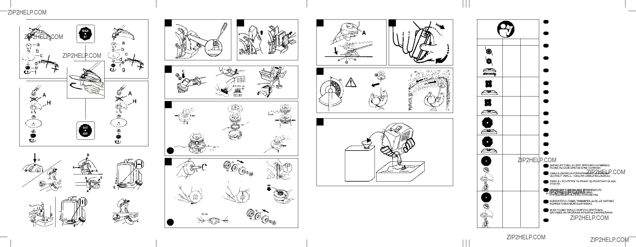
To replace the reel of string, press both the release pawls indicated by the arrows, remove the empty reel, unroll any string left and rewind the new string. Open the original package of string and insert the ends of the two strings in the eyelets on the reel, then wind the strings com- pletely on the reel in the same direction and fas- ten the end of each string in the 2 opposite grooves. Replace the reel in its housing and thread the ends of the strings in their bushings. Pull each string so that about 15 cm comes out on each side. Reassemble the nylon string head as shown (fig. H5). If the reel becomes excessive- ly worn, replace it with a whole new reel.

H3. Replacement of nylon string (B)

1)Loosen the locking nut on the base of the nylon head by turning it clockwise.

2)Remove the base cover assembly.

Remove the empty spool from the housing and discard any remaining line.

3)Prepare 2 lengths (8ft each) of 2.4 mm nylon line. Thread 1 end of each line into the two holes on opposite sides of the spool. Pinch the exposed ends flat with a pair of pliers to pre- vent them slipping through the hole.

4)Wind the two lines in the same direction around the spool.

5)Slide the end of the two lines into the grooves to hold the line temporarily.

6)Position the spool back into the housing and pull the line through the eyelets.

7)Pull about 15cm (5ins) of line out on either side.

8)Reassemble the nylon string head as illustrat- ed; mower gauge,spring and locking nut (tight- en in an anti-clockwise direction).

ENGLISH - 7

I. Techniques for use

10 11 12 13 14 16

Cutting techniques

During the cutting operations, keep the engine running at high speed. After every

cutting stage, decelerate the engine to minimum speed as running it at top speed without a load can damage the engine severely.

Wait until the engine is running at minimum speed before moving the machine from one section to another.

The machine is ideal to complete the work of the lawnmover. In fact, it can reach places where a normal lawnmower is unable to go.

Cutting and trimming grass borders with the nylon string head

Cutting with the nylon string head is suitable for light jobs like trimming borders and cutting the grass around trees.

Mowing

To prevent damage to your lawn or the cutting mechanism, keep the string parallel to the ground but avoid contact with the terrain.

Trimming borders

Angle the nylon string head keeping it a short dis- tance from the ground. Cut using the end of the string. Do not press the string against the material to be cut.

I1. Drawing out the string (A)

During cutting, the nylon string wears naturally causing an increase in the speed of the engine and a reduced cutting capacity. When this hap- pens, to bring out more string bump the head against the ground: release the throttle trigger to reduce the engine speed to less than 8000 rpm.

Tap gently on the ground with the button (A) as shown in the figure and the string will come out automatically. Accelerate again. If the string does not come out make sure there is still some left and try again.

I2. Drawing out the string (B)

In order to extend the nylon line as it wears down, pull the mower gauge downwards and turn it in a clockwise direction to feed out the desired length of line.

I3. Thinning grass with the grass cutter blade

2 16

The grass is cut with swinging motions from side to side, maintaining the blade parallel to the ground. During the right to left swing the grass is cut, while the backswing must be made without using the blade.

KICKBACK can occur when cutting is done with the risk sector of the blade; we recommend cut- ting with the rest of the blade. Take care that the cup supporting the blade just grazes the ground. This will prevent the blade from touching the ground.

Use of sawtooth blade

2 5 11 16

Do not attempt to cut trees with a larger than recommended diameter, to prevent

the risk of kickback or damage to the blade.

The sawtooth blade serves to cut bushes and small trees, with maximum diameter of seven centimeters. Rest the left side of the special shield on the trunk while cutting to limit the risk of losing control of the machine.

L. Environmental information

This section contains information useful for main- taining the characteristics of eco-compatibility included in the origin design of the machine, and as regards proper use and disposal of oil and fuel.

Design

In the design stage, care was taken to develop an engine with reduced consumption and low emis- sions of noise and pollutant exhaust fumes.

Use of machine

The operations of filling the tank with the fuel mix-

ture should be carried out in such a way as to avoid spilling fuel and contaminating the soil and environment.

Periods of prolonged disuse

Always empty the fuel tank with the same precau- tions used in filling it.

Disposal

Do not dispose inappropriately of the machine when it is no longer usable. Deliver it to an authorized organization for proper disposal in compliance with the regulations in force.

ENGLISH - 8

M. Troubleshooting table

The engine continues to have problems: contact your authorized supplier

ENGLISH - 9

N. Declaration of conformity

The undersigned, authorized by Electrolux Outdoor Products Italy S.P.A., declares that the following products model /TYPE: BC010A, BC010B starting from the serial numbers produced from 2003 on, manufactured by Electrolux Outdoor Products Italy S.P.A.., Valmadrera, Italia, comply with European Directive: 98/37/EEC (Machine Directive), 93/68/EEC (EEC Marking Directive) & 89/336/EEC (Electromagnetic Compatibility Directive), directive 2000/14/EEC (Enclosure V).

Valmadrera, 15.12.03

Giuseppe Todero (Technical Manager)

Electrolux Outdoor Products Italy S.P.A.

Via Como 72, 23868 Valmadrera (Lecco) ITALY

O. Technical data

ENGLISH - 10