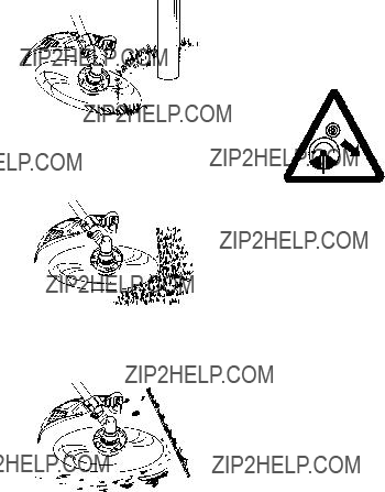
WARNING: The blade continues to
spin after the throttle is released or, engine is turned off. The coasting blade can throw objects or seriously cut if accidentally touched. Stop the blade by contacting the right hand side of the coasting blade with material already cut.
Stop coasting blade by contact with cut material.
OPERATOR SAFETY
 WARNING: This machine produces
an electromagnetic field during operation. Under some circumstances, this field may interfere with active or passive medical implants. To re- duce the risk of serious or fatal injury, we recom- mend persons with medical implants to consult their physician and the medical implant
manufacturer before operating this machine.
S Dress properly. Always wear safety glasses or similar eye protection when op- erating, or performing maintenance, on your unit (safety glasses are available). Eye protection should be marked Z87.
S Always wear face or dust mask if operation is dusty.
S Always wear heavy, long pants, long sleeves, boots, and gloves. Wearing safety
leg guards is recommended.
S Always wear foot protection. Do not go barefoot or wear sandals. Stay clear of blade/spinning line.
SSecure hair above shoulder length. Secure or remove loose clothing or clothing with loosely hanging ties, straps, tassels, etc.
They can be caught in moving parts.
SBeing fully covered also helps protect you from debris and pieces of toxic plants
thrown by spinning line.
SStay alert. Do not operate this unit when you are tired, ill, upset or under the influence of al- cohol, drugs, or medication. Watch what you
are doing; use common sense.
SWear hearing protection. Long or continu- ous exposure to high noise levels may
cause permanent hearing impairment.
S Mufflers fitted with catalytic converters get
very hot during use and remain so for some time after stopping. This also applies at idle speed. Contact can result in burns to the skin. Remember the risk of fire!
S Never start or run inside a closed room or building. Breathing exhaust fumes can kill.
S Keep handles free of oil and fuel.
SAlways use the handlebar and a properly adjusted shoulder strap with a blade (see ASSEMBLY).
UNIT / MAINTENANCE SAFETY
 WARNING: Stop unit and disconnect
the spark plug before performing mainte- nance (except carburetor adjustments).
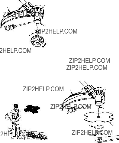
SThrow away blades that are bent, warped, cracked, broken, or damaged in any other way. Replace trimmer head parts that are cracked, chipped, broken, or damaged in
any other way before using the unit.
S Maintain unit according to recommended procedures. Keep blade sharp. Keep cut- ting line at the proper length.
SUse only 3 mm diameter McCulloch brand replacement line. Never use wire, rope, string, etc.
SInstall required shield properly before using the unit.
SUse only specified blade or trimmer head; make sure it is properly installed and se- curely fastened.
SNever start engine with clutch shroud re- moved. The clutch can fly off and cause se-
rious injury.
SBe sure blade or trimmer head stops turning when engine idles.
SMake carburetor adjustments with the low- er end supported to prevent blade or trim- mer line from contacting any object. Hold
unit by hand; do not use the shoulder strap for support.
S Keep others away when making carbure-
tor adjustments.
S Use only recommended McCulloch accesso- ries and replacement parts.
SHave all maintenance and service not ex- plained in this manual performed by your au- thorized service dealer.
FUEL SAFETY
S Mix and pour fuel outdoors.
S Keep away from sparks or flames. S Use a container approved for fuel.
S Do not smoke or allow smoking near fuel or the unit.
S Avoid spilling fuel or oil. Wipe up all fuel spills. S Move at least 3 meters away from fueling
site before starting engine.
S Stop engine and allow to cool before re- moving fuel cap.
S Always store gasoline in a container ap- proved for flammable liquids.
CUTTING SAFETY
 WARNING: Inspect the area to be cut
before each use. Remove objects (rocks, broken glass, nails, wire, string, etc.) which can be thrown or become entangled in the
blade or trimmer head.
S Keep others including children, animals, bystanders, and helpers at least 50 feet (15 meters) away. Stop engine immediately if you are approached.
SAlways keep engine on the right--hand side of your body.
S Hold the unit firmly with both hands.
4


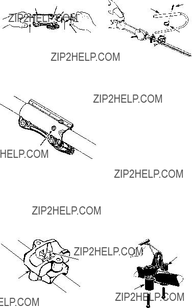


 Screw
Screw


 Nut
Nut