INSTALLATION

INSTRUCTIONS

24??? ELECTRIC BUILT-IN SINGLE CAVITY WALL OVENS

READ ???SAFETY PRECAUTIONS??? IN CARE & USE BOOK BEFORE USING OVEN

NOTICE TO OWNER:

In order to assure the best results in service, proper operation and maximum efficiency, the original installation and adjustment should be made by your dealer, his authorized agent, or by your local utility company before you attempt to operate the oven.

IMPORTANT - SAVE FOR LOCAL ELECTRICAL INSPECTOR???S USE.

INSTALLER: LEAVE THESE INSTRUCTIONS WITH THE HOMEOWNER.

HOMEOWNER: RETAIN THESE INSTRUCTIONS FOR FUTURE REFERENCE.

8101P433-60

(10-01-00)

24??? ELECTRIC BUILT-IN SINGLE CAVITY WALL OVENS

22??? WIDE CUTOUT

2

LOCATION

Place oven where it will be well lighted. For proper baking and cooking results, oven must be level. Use a spirit level on center oven rack to level. THIS ELECTRIC OVEN IS

APPROVED FOR INSTALLATION IN COMBUSTIBLE

CABINETRY. SEE INSTALLATION DIAGRAM FOR THE OVEN.

WARNING

Be sure OVEN is DISCONNECTED from POWER SUPPLY before examining any of the electrical equipment.

OUTSIDE WIRING

Your local utility company will tell you whether the present electric service to your home is adequate. It may be necessary to increase the size of the wiring to the house and service switch to take care of the electrical load demanded by the oven and/or top section. The wattage (K.W. rating) load for the oven is specified on the name plate on the unit.

HOUSE WIRING

Most local building regulations and codes require that all electrical wiring be done by licensed electricians. All wiring should conform to Local or National Electrical Codes. This oven requires a single phase three wire 120/240 or a 120/208 volt, 60 Hz. AC circuit. Wiring codes require that a separate circuit be run from the main entrance panel to the oven and that it be equipped with separate disconnect switch and fuses, either in the main entrance panel or in a separate switch and fuse box.

RANGE CONNECTIONS

The flexible armored conduit supplied with the oven must be connected to an approved electrical junction box by means of an approved conduit to box connector. THE

FRAME OF THE OVEN IS GROUNDED TO NEUTRAL

ONLY WHEN THE WHITE AND BARE WIRES AT THE

END OF OVEN CONDUIT ARE JOINED TOGETHER. Connect the white and bare wire at the end of the oven conduit to the neutral (white) wire of the branch circuit. If used on new branch-circuit installations (1996 NEC), mobile homes, recreational vehicles, or in an area where local codes prohibit grounding through the neutral conductor, untwist or disconnect the bare wire and connect the bare wire to ground in accordance with local code. Connect the white wire to the branch circuit. The red and black wires must be connected to the remaining two conductors of the branch circuit. Connect all wires to the branch circuit with approved connectors. Use copper or aluminum wire. If aluminum wire is used, use connectors recognized for joining aluminum to copper.

NEUTRALL2

BRANCH CIRCUIT

(POWER SUPPLY)

RANGE GROUNDED THROUGH NEUTRAL CONDUCTOR

3-WIRE INSTALLATION

WIRING METHOD IF CODE DOES NOT PERMIT GROUNDING

THROUGH NEUTRAL CONDUCTOR & ALSO REQUIRED IN MOBILE

HOMES.

4-WIRE INSTALLATION

3

INSTRUCCIONES

DE INSTALACI??N

HORNOS EL??CTRICOS EMPOTRADOS DE PARED CON CAVIDAD

SENCILLA DE 24???

LEA LAS ???INSTRUCCIONES DE SEGURIDAD??? EN EL MANUAL DE CUIDADO Y USO

ANTES DE USAR EL HORNO

AVISO AL PROPIETARIO:

Para garantizar los mejores resultados en el servicio, el funcionamiento apropiado y la m??xima eficiencia, la instalaci??n y el ajuste originales debe realizarlos el distribuidor, su agente autorizado o la compa????a de servicios p??blicos locales antes de que intente operar el horno.

IMPORTANTE: CONSERVE ESTAS INSTRUCCIONES PARA QUE LAS USE EL

INSPECTOR EL??CTRICO LOCAL.

INSTALADOR: DEJE ESTAS INSTRUCCIONES CON EL PROPIETARIO.

PROPIETARIO: CONSERVE ESTAS INSTRUCCIONES COMO REFERENCIA

FUTURA.

HORNOS EL??CTRICOS EMPOTRADOS DE PARED CON

CAVIDAD SENCILLA DE 24???

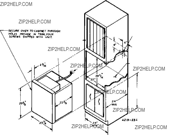
HUECO DE 22??? DE ANCHO

ASEGURE EL HORNO AL GABINETE

MEDIANTE LOS ORIFICIOS PROVISTOS EN

EL ADORNO, LOS CUATRO TORNILLOS

EMBARCADOS CON LA UNIDAD.

FRENTE DEL

GABINETE

CABLE FLEXIBLE DE 7/8??? DE

DI??METRO INTERNO DE 4??? 0???

DE LARGO PROVISTO POR EL

FABRICANTE

CONDUCTORES

EL??CTRICOS

DE 6???

DEJE PREPARACI??N

PARA UNA COLECCI??N EL??CTRICA DE 120/240, 120/208 VOLTIOS EN

ESTA ??REA.

SE RECOMIENDA TENER EL

PISO TERMINADO PARA

EVITAR CORRIENTES DE

AIRE INUSUALES.

33 1/4???

DE

ALTURA

MINIMA

2

UBICACI??N

Coloque el horno en donde est?? bien iluminado. Para obtener los mejores resultados en el horneado y la cocci??n, el horno debe estar bien nivelado. Use un nivel de burbuja en el centro de la parrilla del horno para nivelarlo. ESTE HORNO EL??CTRICO EST??

APROBADO PARA INSTALARSE EN GABINETES

COMBUSTIBLES. VEA EL DIAGRAMA DE

INSTALACI??N PARA EL HORNO.

ADVERTENCIA

Aseg??rese de que el HORNO est?? DESCONECTA- DO del SUMINISTRO EL??CTRICO antes de examinar alg??n equipo el??ctrico.

CABLEADO EXTERIOR

La compa????a local de servicios p??blicos le dir?? si el servicio el??ctrico actual de su casa es adecuado. Podr??a ser necesario tener que aumentar el tama??o del cableado a la casa y el interruptor de servicio para obtener la capacidad de carga el??ctrica que demanda el horno o la secci??n superior. La clasificaci??n de vataje del horno est?? especificada en la placa indicadora de la unidad.

CABLEADO DE LA CASA

La mayor??a de los reglamentos y c??digos de construcci??n requieren que todo el cableado el??ctrico lo realice electricistas con licencia. Todo el cableado deber?? realizarse en conformidad con los C??digos el??ctricos nacionales o locales. Este horno requiere un cable monof??sico de tres hilos de 120/240 o uno de 120/208 voltios, 60 Hz circuito de corriente alterna. Los c??digos de cableado requieren que se establezca un circuito separado del panel de entrada principal al horno y que est?? equipado con un interruptor y fusibles de desconexi??n por separado, ya sea en el panel de entrada principal o en un interruptor y caja de fusibles por separado.

CONEXIONES DE LA ESTUFA

El tubo aislador protegido flexible provisto con el horno debe estar conectado a una caja de empalmes el??ctrica aprobada, mediante un conductor aprobado al conector de caja. EL BASTIDOR DEL HORNO EST??

CONECTADO A TIERRA A UN ALAMBRE NEUTRO

SOLAMENTE CUANDO LOS ALAMBRES BLANCO Y

DESNUDO AL EXTREMO DEL CONDUCTOR DEL HORNO EST??N UNIDOS. Conecte el alambre blanco y el desnudo al extremo del conductor del horno al alambre neutro (blanco) del circuito de derivaci??n. Si se usa en instalaciones de derivaciones nuevas del circuito (1996 NEC), casas m??viles, veh??culos recreativos o en ??reas en donde los c??digos locales prohiben la conexi??n a tierra mediante un conductor neutro, destuerza o desconecte el alambre desnudo y con??ctelo a tierra de acuerdo con el c??digo local. Conecte el alambre blanco al circuito de derivaci??n. Los alambres rojo y negro deben estar conectados a los dos conductores restantes del circuito de derivaci??n. Conecte todos los alambres al circuito de derivaci??n con conectores aprobados. Use alambre de cobre o aluminio. Si se usa alambre de aluminio, use los conectores indicados para unir aluminio a cobre.

ESTUFA CONECTADA A TIERRA MEDIANTE UN CONDUCTOR NEUTRO

INSTALACI??N DE 3 ALAMBRES

M??TODO DE CABLEADO SI LOS C??DIGOS NO PERMITEN LA CONEXI??N A

TIERRA MEDIANTE UN CONDUCTOR NEUTRO Y QUE TAMBI??N SE

REQUIERE EN LAS CASAS M??VILES.

INSTALACI??N DE 4 ALAMBRES

3

MISE EN

SERVICE

FOURS ??LECTRIQUES ENCASTR??S DE 24 PO ?? UNE CAVIT??

LIRE LES ???MESURES DE S??CURIT????? DANS LE MANUEL DE L???UTILISATEUR AVANT

D???UTILISER LE FOUR.

?? L???INTENTION DE L???UTILISATEUR :

Pour assurer un fonctionnement correct et efficient et des r??sultats optimums au niveau du service apr??s-vente, la pose et le r??glage initiaux doivent ??tre r??alis??s par le revendeur, son prestataire agr???? ou par la compagnie de gaz ou d?????lectricit??, selon le cas, avant d???utiliser le four.

IMPORTANT - CONSERVER POUR L???INSPECTEUR D?????LECTRICIT?? LOCAL.

INSTALLATEUR : VEUILLEZ LAISSER CETTE NOTICE DE MISE EN SERVICE ??

L???UTILISATEUR.

UTILISATEUR : VEUILLEZ CONSERVER CETTE NOTICE DE MISE EN SERVICE

POUR R??F??RENCE ULT??RIEURE.

FOURS ??LECTRIQUES ENCASTR??S ?? UNE CAVIT?? DE 24 PO

D??COUPE DE 22 PO DE LARGE

HAUTEUR

MIN. DE 33 1/4 PO

2

EMPLACEMENT

Mettre le four dans un endroit o?? il recevra un bon ??clairage. Pour des r??sultats optimums ?? la cuisson, le four doit ??tre de niveau. Le mettre de niveau ?? l???aide d???un niveau plac?? sur la grille centrale. CE FOUR

??LECTRIQUE EST HOMOLOGU?? POUR ??TRE

ENCASTR?? DANS UNE ARMOIRE EN MAT??RIAU

COMBUSTIBLE. VOIR LE DIAGRAMME DE POSE

DU FOUR.

RACCORDEMENT AU SECTEUR

La compagnie d?????lectricit?? locale vous indiquera si votre branchement est pr??vu pour fournir la puissance exig??e par l???appareil. Il pourra ??tre n??cessaire d???augmenter la grosseur des c??bles amenant l?????lectricit?? ?? la maison et au panneau de distribution ??lectrique pour assurer l???alimentation qui convient au four et/ou ?? la partie sup??rieure. La puissance ??lectrique du four (en kW) est sp??cifi??e sur la plaque signal??tique.

INSTALLATION ??LECTRIQUE DE LA

MAISON

La plupart des codes et r??glements relatifs ?? la construction exigent que l???installation ??lectrique d???une maison soit r??alis??e par un ??lectricien qualifi??. Le c??blage doit ??tre conforme aux codes d?????lectricit?? local ou national. Ce four requiert un circuit alternatif monophas?? trifilaire de 120/240 V ou 120/208 V et 60 Hz. Les codes exigent que le four soit dot?? d???un circuit s??par?? partant du panneau de distribution ??lectrique et que celui-ci soit prot??g?? par un sectionneur et des fusibles, au niveau du panneau de distribution ??lectrique ou dans un coffret ??lectrique s??par??.

CONNEXIONS DE LA CUISINI??RE

Le conduit flexible arm?? fourni avec le four doit ??tre raccord?? ?? une bo??te de d??rivation homologu??e au moyen d???un conduit homologu?? raccord?? au connecteur de la bo??te de d??rivation. LE CH??SSIS DU FOUR EST RELI??

?? LA MASSE AU NEUTRE UNIQUEMENT LORSQUE

LES FILS BLANC ET NU ?? L???EXTR??MIT?? DU CONDUIT DE C??BLES DU FOUR SONT CONNECT??S. Connecter le fil blanc et le fil nu de l???extr??mit?? du conduit de c??ble du four au fil neutre (blanc) du circuit de d??rivation. Dans le cas de circuits de d??rivation nouvellement install??s (NEC 1996), de maisons mobiles, de v??hicules de loisir ou s???il s???agit d???une r??gion o?? les codes locaux interdisent la mise ?? la terre par le neutre, d??tordre le fil nu ou le d??connecter et le raccorder ?? la terre conform??ment au code local. Raccorder le filtre blanc au circuit de d??rivation. Les fils rouge et noir doit ??tre raccord??s aux deux conducteurs restants du circuit de d??rivation. Raccorder tous les fils au circuit de d??rivation avec des connecteurs homologu??s. Utiliser du fil de cuivre ou d???aluminium. En cas d???utilisation de fil d???aluminium, utiliser les connecteurs con??us pour raccorder de l???aluminium

au cuivre.

AVERTISSEMENT :

S???assurer que le FOUR est D??BRANCH?? du SECTEUR avant toute v??rification du mat??riel ??lectrique.

CONNECTEUR

HOMOLOGU??

CONDUIT DE

C??BLE DU FOUR

NOIRROUGE

NU

BLANC

BO??TE DE D??RIVATION

HOMOLOGU??E

NEUTREL2

CIRCUIT DE D??RIVATION

(ALIMENTATION ??LECTRIQUE)

CUISINI??RE RELI??E ?? LA MASSE PAR LE CONDUCTEUR NEUTRE

INSTALLATION ?? TROIS FILS

M??THODE DE C??BLAGE SI LE CODE NE PERMET PAS LA MISE ?? LA MASSE

PAR LE CONDUCTEUR NEUTRE, ??GALEMENT REQUISE DANS LES

MAISONS MOBILES.

INSTALLATION ?? 4 FILS

3