IMPORTANT SAFETY AND WARNIING
INFORMATION
read THIS MANUAL IN ITS ENTIRETY and under- stand these Rules to follow for safety.
 WARNING
Improper installation, adjustment, alteration, ser- vice or maintenance can cause injury or property damage. Refer to this manual. For assistance or additional information consult a qualified installer, service agency or the gas supplier.
 WARNING
Do not attempt to alter or modify the construction of the appliance or its components. Any modification or alteration may void the warranty, certification and listings of this unit.
1.DO NOT CONNECT THIS UNIT TO A CHIMNEY FLUE SERVING
ANOTHER APPLIANCE.
2.Do not connect this appliance to air ducts or any air distribu- tion system.
3.DO NOT INSTALL A FLUE DAMPER IN THE EXHAUST VENTING
SYSTEM OF THIS UNIT.
4.Do not use class B venting intended for gas appliances as a chimney or connector pipe on a pellet-fired appliance.
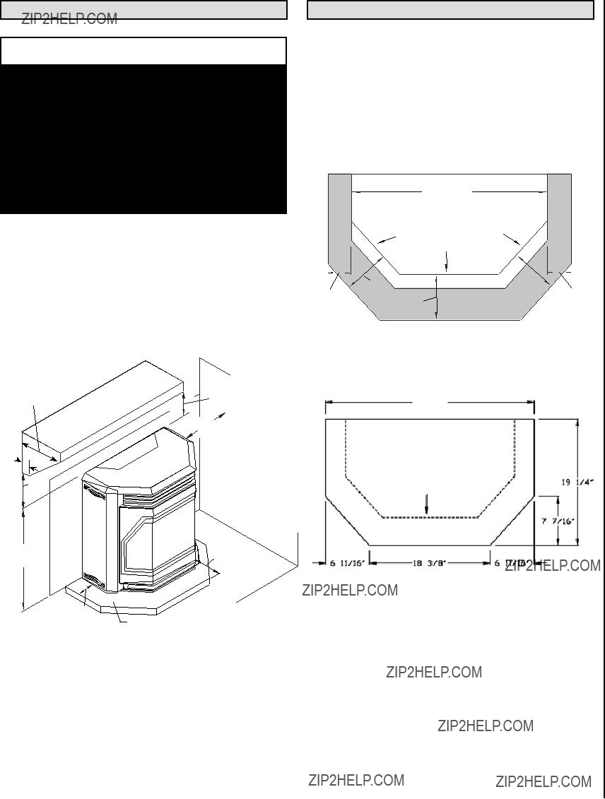
5.The minimum clearances must be maintained for all com- bustible surfaces and materials including; furniture, carpet, drapes,clothing,wood,papers,etc.Donotstorecombustibles within this clearance space (see Clearances on Page 7).
6.INSTALLATION DISCLAIMER - It is imperative that the exhaust venting system be installed correctly and sealed gas-tight (not allowing exhaust to leak). Follow the vent manufacturer's instructions for proper installation. Since Lennox Hearth Products has no control over the installation of your fire- place insert, Lennox Hearth Products grants no warranty, implied or stated for the installation or maintenance of your insert, and assumes no responsibility for any consequential damage(s).
7.Burning any kind of fuel consumes oxygen. If outside air is not ducted to the appliance, ensure that there is an adequate source of fresh air available to the room where the appliance is installed.
8.The appliance will not operate using natural draft, nor without a power source for the blower and fuel feeding systems.
9.Never use gasoline, gasoline-type lantern fuel, kerosene, charcoal lighter fluid, or similar liquids to start or ???freshen up??? a fire in this heater. Keep all such liquids well away from the heater while it is in use.
10.The authority having jurisdiction such as municipal build- ing department, fire department, fire prevention bureau, etc
should be consulted before installation to determine the need
to obtain a permit.
�
10.APPROVED FUEL: This appliance is designed specifically for use only with pelletized wood fuels only. This appliance is designed and approved for the burning of wood residue pellets with up to 3% ash content. This appliance is NOT approved to burn cardboard, nut hulls, cherry pits, corn, etc. regardless if it is in pellet form. Failure to comply with this restriction will void all warranties and the safety listing of the fireplace insert. Consult with your Lennox Hearth Products dealer for more information on approved pellet fuels.
11.These appliances are designed as supplemental heaters. Therefore, it is advisable to have an alternate heat source when installed in a dwelling.
12.CONTINUOUS OPERATION: When operated correctly, this appliance cannot be overfired. Continuous operation at a maximum burn can, however, shorten the life of the electri- cal components (blowers, motors, and electronic controls), and is not recommended. Typical approved operation would include running at the low to mid range setting with occasional running on the maximum setting during the coldest periods of the winter. DO NOT OVER-FIRE THIS INSERT. Follow all instructions regarding the proper use of this insert.
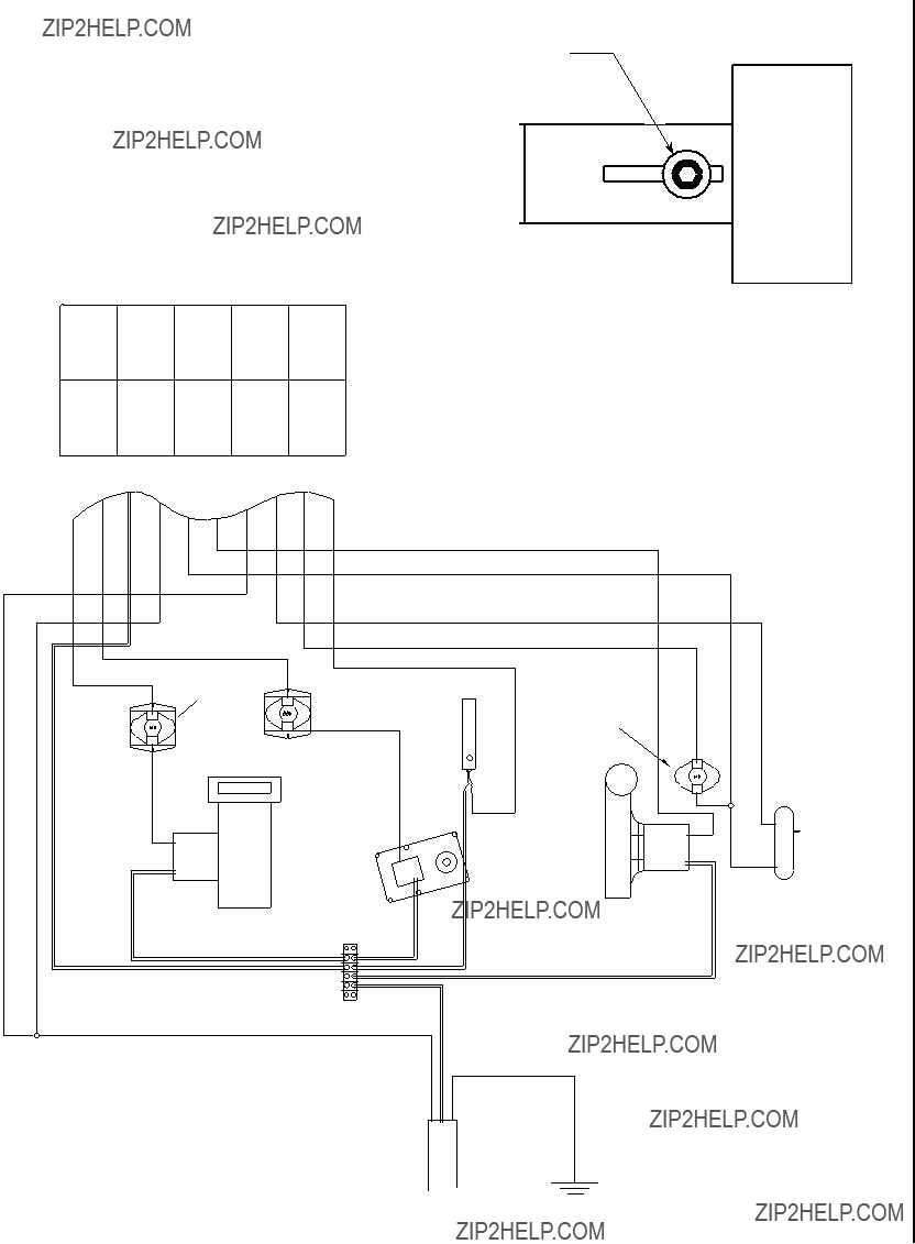
13.CAUTION: NEVER PUT FINGERS NEAR AUGER. Pellet fuel is fed to the UltraGrate??? by a screw auger. This auger is driven by a high torque motor. The auger is capable of doing seri- ous harm to fingers. Keep pellets in the hopper at all times and keep fingers away from auger. The auger can start and stop automatically at any time while the insert is running.
14.CAUTION: NEVER PUT FINGERS NEAR AUGER. Pellet fuel is fed to the UltraGrate??? by a screw auger. This auger is driven by a high torque motor. The auger is capable of doing serious harm to fingers. Keep pellets in the hopper at all times and keep fingers away from auger. The auger can start and stop automatically at any time while the insert is running.
15.FLY ASH BUILD-UP: For all wood pellet fuel-burning heaters, the combustion gases will contain small particles of fly-ash. This will vary due to the ash content of the fuel being burned. Over time, the fly-ash will collect in the exhaust venting system and restrict the flow of the flue gases. The exhaust venting system should be inspected regularly and cleaned as necessary.
16.SOOT FORMATION: Incomplete combustion, such as occurs during startup, shutdown, or incorrect operation of the room heater will lead to some soot formation which will collect in the exhaust venting system. A precautionary inspection on a regular basis is advisable to determine the necessity of cleaning. The exhaust venting system should be inspected regularly and cleaned as necessary.
17.DISPOSING OF ASHES: Any ashes removed from the pellet fireplace insert must be deposited in a metal container with a tight-fitting lid. The closed container of ashes should be placed on a noncombustible floor or on the ground, well away from all combustible materials, outside of the dwell- ing pending final disposal. If the ashes are disposed of by burial in soil or otherwise locally dispersed, they should be retained in the closed container until all cinders have been thoroughly cooled.
19.The instructions must be strictly adhered to. Do not use makeshift methods or compromise in the installation.
20.Do not abuse the door glass by striking, slamming or similar trauma. Do not operate the insert with the glass removed, cracked or broken.
18.SAVE THESE INSTRUCTIONS.
19.See the listing label on the appliance.

 WARNINGS

 WARNING
 WARNING
 CAUTION
 CAUTION
 (387mm)
 IMPORTANT


 B
B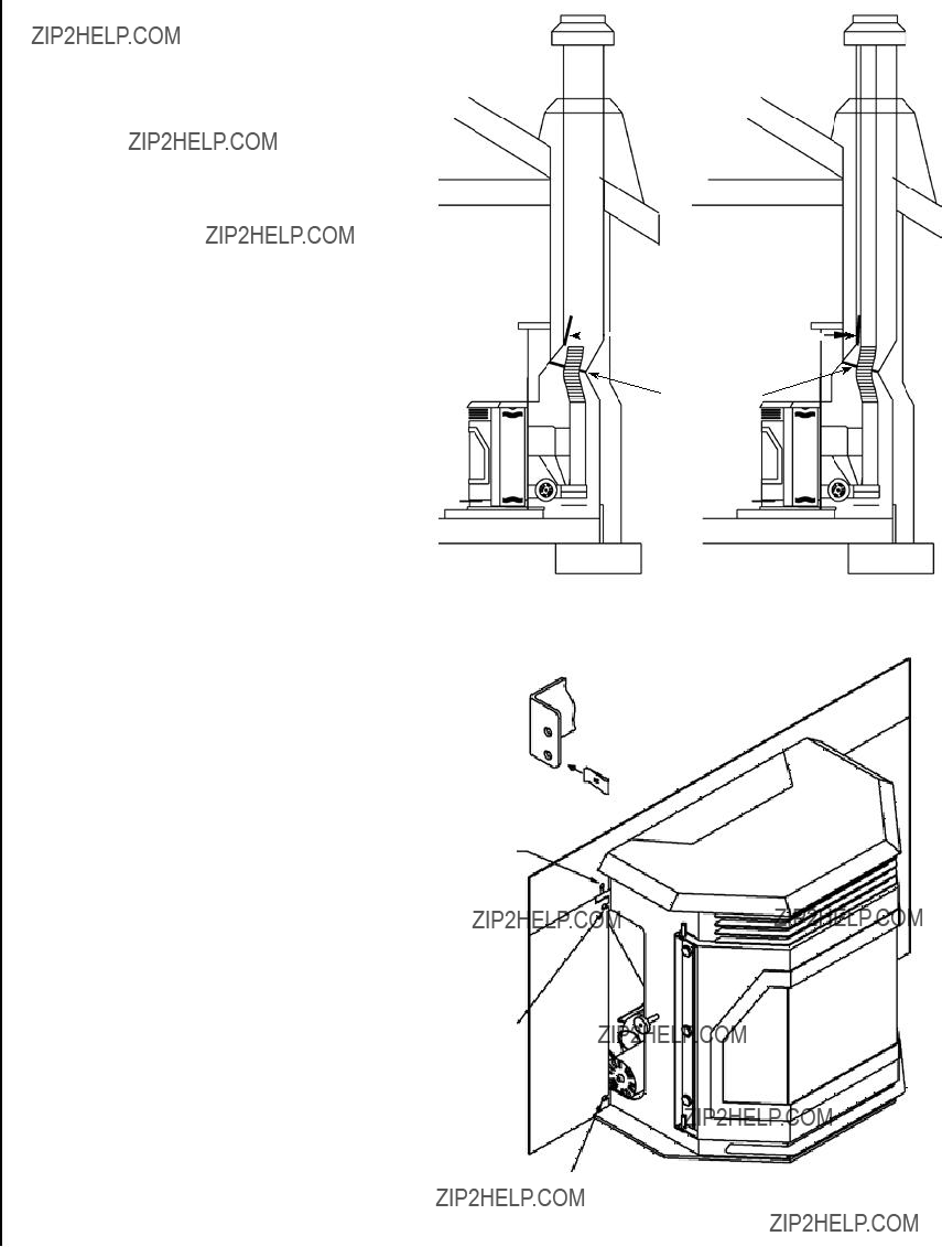


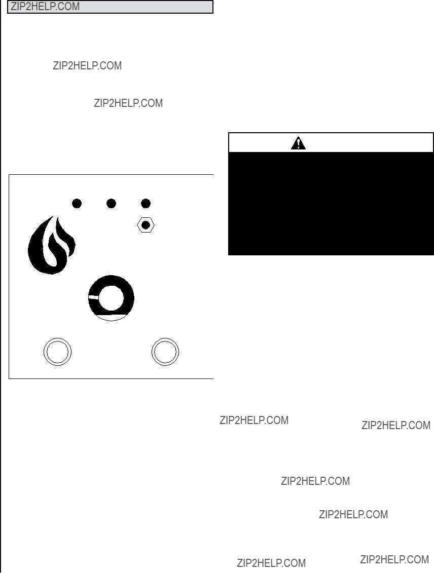

 Heat Selector


 A
A

 C
C