PLEASE READ ALL INSTALLATION
INSTRUCTIONS AND REQUIREMENTS
BEFORE INSTALLING
WARNING
OR'IOURSAFETY
Do not store or use gasoline or other flammable vapors or liquids in the
vicinity of this or any other appliance.
'h'1,
ELECTRIC
1
PLEASE READ ALL INSTALLATION
INSTRUCTIONS AND REQUIREMENTS
BEFORE INSTALLING
WARNING
OR'IOURSAFETY
Do not store or use gasoline or other flammable vapors or liquids in the
vicinity of this or any other appliance.
'h'1,
ELECTRIC
1

NSTALLATION REC!UREMENTS
PLEASE READ All Installation Instructions and Requirements Before Installing Power Cord.
IT IS RECOMMENDED THAT A QUALIRED ELECTRk ClAN OR SERVICETECHNICIAN INSTALLYOUR DRYER.
LOCATION
This clothes dryer is designed so that it can be installed in most locations in the home. The dryer may even be installed in an unheated indoor location, such as a utility room or building. However, with models hav- ing automatic dry cycles, the TIME DRY SETTING
SHOULD BE USED WHEN THE ROOM TEMPERA-
TURE DROPS BELOW 50 DEGREES FAHRENHEIT
OR (10 DEGREES C.), AS THE AUTOMATIC CYCLE
MAY NOT SHUT OFF.
DO NOT INSTALL THE DRYER ON A CARPETED
FLOOR.
DO NOT INSTALL OR STORE THE DRYER WHERE
IT MAY BE EXPOSED TO THE WEATHER OR DRIP-
PING WATER. IF IT IS EVER EXPOSED TO WATER,
HAVE A QUALIFIED TECHNICIAN CHECK IT
BEFORE USING.
THE INSTALLATION MUST BE MADE WITH ADEQUATE
CLEARANCE TO PERMIT SERVICING.
In ordinary installations enough air will be available for prop- er operation of the dryer. However, if the dryer is installed in a mobile home, a closet or a tightly sealed room, provisions should be made for at least 18 square inches of ventilation
Dryers installed in manufactured (mobile) homes must be connected with 4 conductor type SRD or SRDT cord to a 3
pole, 4 wire grounding type receptacle; by
using
feet free to permit moving the dryer.
Where permitted by local codes, a flexible power cord (pig- tail) may be connected to the dryer. A receptacle should be installed in a separate circuit connected to the main service entrance panel for this type of installation. See Figure #3.
Use only a 3 or 4 wire power cord kit, includingstrain relief,
listed by U.L. for use with dryers. The power cord must have a rating of 30 amperes, 120/240 voltsAC minimum and be terminated in closed loop or open spade lugs with upturned
ends. The attachment plugof the power cord and the recep- tacle to which it willbe connected must have a minimum cur-
rent rating of 30 amps and have matching configurations. Typical30 ampere configurations are illustrated in figure #3.
GROUNDING INSTRUCTIONS
This appliance MUST BE CONNECTED TO A GROUNDED METAL PERMANENT WIRING SYSTEM; or an equipment- groundingconductormust be run with the circuitconductors and connected to the
CONNECTINGTHEDRYER
II
must be exhausted outdoors.
ELECTRICAL REQUIREMENTS
This phase of the installation should be done by a qualified service technician or electrician in accordance with the
dryer circuit must be No. 10 gauge copper wire for up to 40
ft. lengths and No. 8 gauge copper wire for up to 60 ft.
Lengths.NEVER USE A TWO WIRE CABLE WITH AN
UNINSULATED GROUND WIRE TO CONNECT THE
DRYER.
The National Electric Code requires that a means to discon-
nect all ungrounded conductors (line 1 and line 2) to the dryer be provided for service. If a power cord and receptacle
THE NATIONAL ELECTRICAL CODE AND ALL
LOCAL CODES AND ORDINANCES MUST BE
OBSERVED WHEN CONNECTING THIS DRYER.
1.To gain access to the terminal block, remove the supply cord cover plate attached to the rear of the dryer.

TYPICAL ELECTRICAL CONNECTIONS
and line 2 terminals of the terminal block as shown in
Plug - NEMA
internal green ground wire or brass strap from the Neutral terminal and the ground screw. Connect the power cable conductors to the line 1, Neutral, and line 2 terminals as shown in Figure #2.
NOTE; An
or conduit installation.
approved grounding type strain relief clamp connector must be installed for this type of
3

FOOT
Set all leveling feet at same height. A minimum of Y2'clearance between the machine and the floor is recommend- ed. Adjust to match the height of your dryer,
WITH HANDS
TO CHECK IF /
LEVELAND
STABLE
Place dryer in the location where it will be used. Check, by rocking dryer with hands on opposite corners, that all four (4) feet are in firm contact with the floor. If it rocks, adjust as needed.
rBASEMENTWIJNBOW
exhaust vent. Outside exhaust vent should fit over dryer vent pipe to avoid
catching lint.Tape all joints with heat duct tape.
I Attach dryer vent pipe to outside
WALL
SIDEVIEW_o
'
In basements, the exhaust can be ele- vated by installing elbows to raise the vent hood above the ground level,
ed downwardthrough the floor may be
used If not possible, the dryer may be tratedexhaustedlaterthroughinthis manualbottom.the as illus-
If space permits, a 4" dia. elbow point-
3D. INDOOREXHAUSTING
(NOT RECOMMENDED unless conditionson page 6 are met.)
._,
__
When exhausting indoors, use the
indoor exhaust kit and maintain a mini- mum clearance of 6 inches between the
rear of the dryer and any adjacent wall.
Read further instructions in this manual, Page 6.
4. ELECTRICAL CONNECTION INSTALLATIONWlTH
POWERCORD (PIGTAIL).
POWER CORD
ATTACHMENT WALL
This appliance must be connected to a grounded metal, permanent wiring system; or an equipment - grounding conductor must be run with the cir-
cuit conductors and connected to the equipment - grounding terminal or lead on the appliance.
4

EXHAUST VENTING RECUIREMENTS
NEVER EXHAUST INTO A CHIMNEY, DUCT, GAS
VENT, WALL, CEILING, ATTIC, CONFINED SPACE,
BEDROOM, OR UNDER A BUILDING.
DO NOT USE VINYL, PLASTIC, CLOTH OR OTHER
NONMETALIC DUCT TO EXHAUST THE DRYER.
MULTIPLE INSTALLATIONS REQUIRE INDIVIDUAL
EXHAUST SYSTEMS.
DRYERS INSTALLED IN A MANUFACTURED
(MOBILE) HOME MUST BE VENTED OUTDOORS.
PERIODICALLY CLEAN LINT FROM VENT SYSTEM.
CLEAN FREQUENTLY IF USING MAXIMUM
LENGTH OF VENT.
Exhausting can be accomplished directly from the rear of the cabinet, through right side of the cabinet, or down- ward through the cabinet base. If your existing ductwork is plastic, nonmetal, or combustible, replace it with METAL. Standard four inch diameter galvanized or aluminum pipe should be used. DO NOT use any pipe which may be sus-
ceptible to rust or COMBUSTION. To avoid catching lint
the crimped end of each pipe section should face away extend into the exhaust pipe or duct.
Flexible 4" diameter metal tubing may be used for exhausting the dryer. However, the convolutions create a
greaterfrom he restrictdryer. ionDo thannot usepipescrewsand seriousor other blockagefasteners canthat result if the tubing is bent too sharply. If clearance to the
wall is less than 8 inches, use a 4" sheet metal elbow at
the rear of the dryer to avoid a sharp bend in the tubing. Do not use over 8 feet (2.5 m.) of flexible metallic tubing between the elbow and the vent hood.
When the dryer stops the damper automatically closes to prevent drafts and the entrance of insects and rodents. To
avoid restricting the outlet, maintain a minimum 8 inch clearance between the hood and the ground or other
obstruction.
FIG. #4
PECONNECTION
EXHAUSTFLOWEXHAUSTFLOW
Vent should never exceed 0.6 inches water column back pressure, fluff empty dryer.
BOTTOM EXHAUSTING
If space permits behind the dryer, a 4" elbow pointeddown-
ward may be used to pass the exhaust system through the floor. If this is not possible, the dryer may be exhausted
through the bottom as illustrated in FIG. #7. When exhaust-
ing in this manner, the installation should be made accord- ing to the following steps:
1. Disconnect electric cord.
2. Raise the top of the dryer by pressing in with a putty knife on the top panel retaining clips. FIG. #5.
,__.,__, _
3.Remove front panel by removing two '/4"screws inside top corners of front panel. Disconnect door switch wires. NOTE position of front seal before removing front panel.
4.Remove the cylinder as follows:
GROOVED SIDE /
OF BELT UP
a.Force idler pulley to the right and remove cylinder belt from idler and motor pulleys. See FIG. #6.
c. Lift out of cabinet.
5. Remove tape and screw securing dryer vent pipe.
b. Lift up and turn cylinder to clear the roller supports.
6. Remove the 4" dryer vent pipe and shorten to a suitable
CORRECTINCORRECT
LENGTHOFVENT
MaximumLengthof 4" RigidDuct
I
length. Length depends on type of elbow purchased. 7. Remove knockout from dryer base.
8.Place dryer in position and mark duct location on floor. Check floor joist location before sawing hole in floor.
5
9.Saw a 4',"_hole in floor and position dryer.
10.Secure the shortened pipe to the blower housing with a
screw at the top and seal all joints with tape or silicone bathtub caulk.
11. Install a 4" 90 degree elbow as shown.
12.Seal rear opening of cabinet withthe coverplate provid- ed with your dryer. Located with literature. Attach cover plate to rear of the cabinet with #8 sheet metal screws or duct tape. (Not supplied)
13.Place cylinder belt around cylinder with grooved side
toward cylinder. FIG. #6.
14. Reinstall cylinder by pushing and turning until rollers are snapped in cylinder grooves and cylinder turns freely.
15. Position cylinder belt with grooved side around motor pulley. Pull idler pulley right until smooth side of belt can be routed around left side of idler pulley. FIG. #6.
16. Rotate cylinder
17, Replace dryer front and reconnect door switch wires,
Make sure the front seal is in the original position, 18. Complete exhaust system to outdoors,
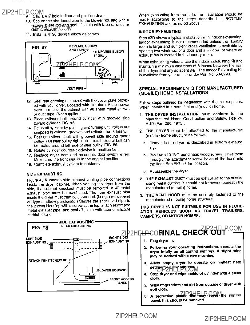
SIDE EXHAUSTING
Figure #8 illustratesside exhaust venting pipe connections inside the dryer cabinet. When venting the dryer from the side, the cabinet knockout must be removed. A 4" metal exhaust pipe must be purchased. The rear exhaust pipe inside the dryer must then be shortened. (Length will depend on type of elbow purchased.) Secure the shortened pipe to
the Blower Housing with a screw at the top, attach elbow and metal exhaust pipe, and seal all joints with tape or silicone
bathtub caulk.
SIDE EXHAUSTING
When exhausting from the side, the installation should be made according to the steps described in BOTTOM EXHAUSTING and as noted above.
INDOOR EXHAUSTING
Step #3D shows a typical installationwith indoor exhausting. Indoor exhausting is not recommended unless the laundry room is large and sufficient cross ventilation is available by opening two windows, or a door and a window, or where an
When exhausting indoors, use the Indoor Exhausting Kit and
of the dryer and any adjacent wall. The Indoor Exhausting Kit
exhaust fan is located in the laundry room.
maintalablein minimyourm clearance of 6 inches between the rear iSavai from dea er under Part No.
SPECIAL REQUIREMENTS FOR MANUFACTURED
(MOBILE) HOME INSTALLATIONS
Follow steps outlined for installation with these exceptions: When installed in a manufactured (mobile) home.
1. THE DRYER INSTALLATION must conform to the
Manufactured Home Construction and Safety, Title 24, HUD (Part 280, 1975).
2. THE DRYER must be attached to the manufactured (mobile) home structure as follows:
a.Dismantle the dryer as described in bottom exhaust- ing.
b. Buy two #10 1'/2rou"nd head wood screws. Drive them
through the attachment screw holes of the base into the floor. See FIG. #8 for location.
c. Reassemble the dryer.
2.THE EXHAUST DUCT must be exhausted to the outside using metal ducting.It should not terminate beneath the manufactured(mobile)home.
3. THE VENT HOOD must be securely fastened to the manufactured (mobile) home structure.
THIS DRYER IS NOT SUITABLE FOR USE IN RECRE-
ATION VEHICLES SUCH AS TRAVEL TRAILERS,
CAMPERS, OR MOTOR HOMES.
LEFT SIDEi111RIGHT SIDE