Specification
 Standard equipment
No
 Optional accessories
Standard equipment
No
Optional accessories

CAUTION: Repair the machine in accordance with ???Instruction manual??? or ???Safety instructions???.
[1] NECESSARY REPAIRING TOOLS
[2] LUBRICATIONS/ GLUING
Apply Makita grease N.No.2/ Loctite 603 to the portions designated by arrows.
Housing L

P 3/ 13
 Repair
[3] DISASSEMBLY/ASSEMBLY
DISASSEMBLING
1)Remove Light cover by unscrewing two M4x8 Pan head screws. (Fig. 2)
2)Remove LED circuit and its Lead wires from Light holder, and disconnect Connector of LED circuit with that of Motor control unit. Switch lever and Compression spring 2 can be removed in this step. (Fig. 3)
1)Connect Connector of LED circuit with that of Motor control unit. and put LED circuit in place on Light holder. Then fix lead wires with Lead holders as illustrated in Fig. 4.
2)Fitting the protruding portion of Light cover in the notch of Angle head complete, assemble Light cover to Angle head complete by screwing two M4x8 Pan head screws. (Fig. 5)
Note: Be careful not to pinch the slack portion of Lead wires between Light cover and Angle head complete.
Fig. 4
Note: Put Connectors and the slack portion of Lead wires in this space. Do not put them on Switch unit and the rib.
Fig. 5
[3]
DISASSEMBLING
1)Remove Bearing retainer
2)Remove Flat washer 6 from Spindle A complete. (Flat washer 6 may remain in Angle head complete.)
Remove Spindle A complete from Bearing retainer
Note: If cannot be removed by hand, disassemble by pressing down Spindle A complete using arbor press. (Fig. 9)
Fig. 6Fig. 7
Spindle A complete section
Bearing 


 retainer
P 4/ 13
 Repair
[3] DISASSEMBLY/ASSEMBLY
[3]
ASSEMBLING
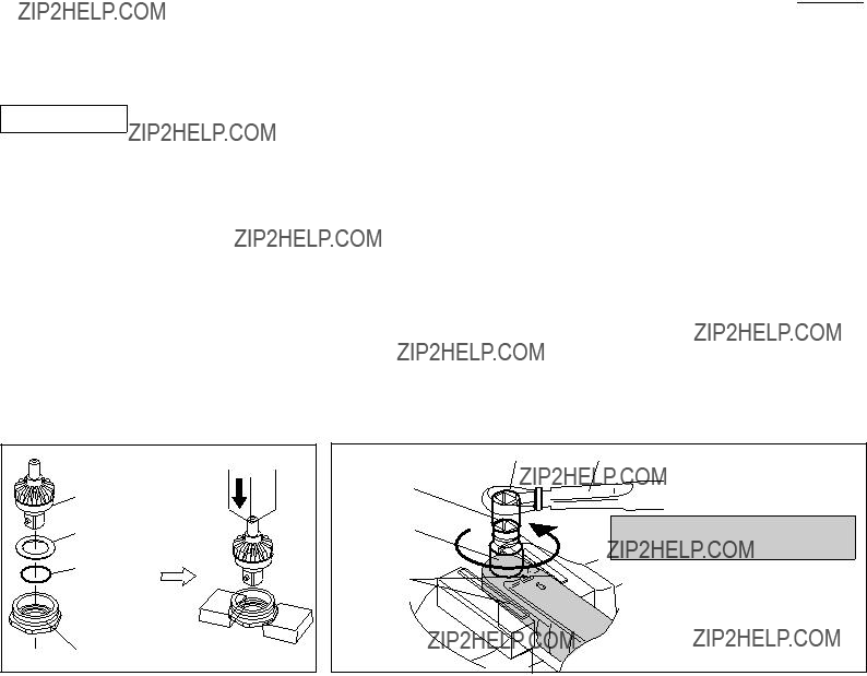
1)Apply Makita grease N.No.2 to O ring 14. (Fig. 1)
Assemble O ring 14, Flat washer 14 then Spindle complete to Bearing retainer
Note: If you cannot assemble Spindle complete to Bearing retainer
Fig. 11.
2)Apply about 2g of Makita grease N.No.2 to the Gear room of Angle head complete. (Fig. 1) Note: Be careful not to put Makita grease N.No.2 on the threaded portion of Angle head complete.
3)Apply Loctite 603 to the threaded portion of Bearing retainer
4)Clamp the flats of Angle head complete securely in a vise to which 1 set of 1R041 is attached, then assemble Spindle A complete section to Angle head complete by turning Bearing retainer
Caution: When clamping Angle head complete, be very careful not to deform it by overtightening.

P 5/ 13
 Repair
[3] DISASSEMBLY/ASSEMBLY
[3]
DISASSEMBLING
1)Remove Light cover by unscrewing two M4x8 Pan head screws, then remove Switch lever and Compression spring 2. (Fig. 12)
2)Remove Angle head complete from Housing by unscrewing four M4x22 (+) Pan head screws, then remove Clutch section (= Clutch assembly) from Angle head complete. (Fig. 13)
Note: Be careful not to lose Compression spring 5, which may pop out from Clutch section when Clutch section is removed from Angle head complete. (Fig. 13)
4)Remove Retaining ring
Fig. 16
Spiral bevel gear 9
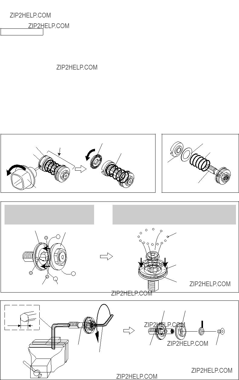
ASSEMBLING
Do the reverse of the disassembling steps. (Refer to Figs. 16 to 12.) Note 1: Spacer is not reversible when assembled to Spiral bevel gear 9.
Be sure to assemble as illustrated to left in Fig. 17.
Note 2: Use 1R034 and arbor press when assembling Ball bearing 6900LLB to Spiral bevel gear 9. (Fig. 18)
Fig. 17Fig. 18
Arbor press
Spiral bevel gear 9  Needle baring 1210
  Spacer

Ball bearing 6900 LLB
 1R034
1R034
P 6/ 13
 Repair
[3] DISASSEMBLY/ASSEMBLY
[3]
DISASSEMBLING
Note: When repairing Clutch section, it is recommended to entirely replace Clutch assembly with new one. However, if required to replace component parts of Clutch assembly, follow the disassembling/assembling procedure described below.
1)Take out Clutch section (=Clutch assembly) from Angle head complete. (Refer to Figs. 12 and 13)
2)Insert
3)Remove Adjust ring complete, Flat washer 18, Compression spring 19H from Spindle. (Fig. 20)
4)The following Steel balls can be removed as illustrated in Fig. 21: Steel ball 3 (13pcs.), Steel ball 4 (3pcs.), Steel ball 5.0 (3pcs.)
Note: Use a screwdriver magnetized with 1R288 for easy removal of Steel balls.
5)Insert short leg of hex wrench 6 into the hole of Spindle, and fix long leg of the hex wrench securely in vise.
Insert No.T25 Torx wrench of L type Torx wrench set (1R145) into the socket of M5x10 Torx countersunk head screw.
Then remove the screw by turning M5 Torx wrench counterclockwise as illustrated to left in Fig. 22.
The following parts can now be removed from Spindle: Cam D, Cam A on Torx screw side, Flat washer 7.(right in Fig. 22)
Steel ball 4 (3pcs.) and Steel ball 5.0 (3pcs.) can be removed by moving Cam D towards the threaded end of Spindle.
After removing Steel ball 4 (3pcs.) and Steel ball 5.0 (3pcs.), Steel ball 3 (13pcs.) can be removed by moving *the Cam on Torx screw side towards Cam D.
Steel ball 3.0 (13pcs.)
Cam A on Torx screw side
M5x10 Torx countersunk head screw 
Cam D Cam A on Torx screw side Flat washer 7

P 7/ 13
 Repair
[3] DISASSEMBLY/ASSEMBLY
[3]
ASSEMBLING
Do the reverse of the disassembling steps.
Note:
 When fastening M5x10 Torx countersunk screw to Spindle, do as described in Fig. 23.
 Apply Makita grease N. No.2 to all Steel balls and the Spindle's threaded portion for enaging with M12 Lock nut before assembling. (Fig. 1) Be careful not to put the grease in the threaded hole of Spindle.
Fig. 23
M5x10 Torx countersunk head screw
 Clean up this threaded portion with gasoline
 or kerosene to remove oil or grease.
 Clean up this threaded hole with gasoline or kerosene to remove oil or grease from the inner threaded portion.
 Put about three drops of Loctite 603 in this threaded hole.
Fix Spindle in vise.
Then fasten M5x10 Torx countersunk head screw to
the recommended torque of
Spindleclockwise using 1R219, 1R220, 1R222 and 1R314. Note: Wipe away any adhesive that might ooze out.

 1R219
1R219

 1R220
1R220 


 1R222
1R222

 1R314
1R314
[3]
DISASSEMBLING
1)Remove Light cover, Switch lever and Compression spring 2. See [3]
2)Remove four M4x22 Pan head screws to separate Angle head complete from the machine. (See [3]
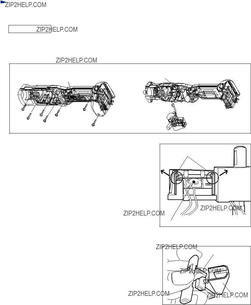
3)Remove seven M3x20 Pan head screws to separate Housing (L) from (R).
4)Remove Switch unit from Gear case section.
5)Separate Gear case section from Motor control unit by first lifting them up, then turning Motor bracket counterclockwise. (Fig. 24)
6)Pull off Motor bracket from Rotor, and then pull off Rotor from Motor control unit.
7)Remove Lock washer located in Gear case by turning counterclockwise with pliers or slotted screwdriver. (Fig. 25)
8)Remove Spur gears, Internal gear 47, Carrier complete B and Ball bearing 6805LLB.
 Turn Motor bracket counterclockwise, and then
  Separate Gear case section from Motor control unit.
Fig. 25
Lock washer
Gear case section
 Turn Lock washer counterclockwise using pliers or slotted screwdriver, and
 Remove from Gear case section.
Caution for Handling Rotor
When handling or storing multiple Rotors, be sure to provide the minimum distances specified in Fig. 26 between Rotors. Rotor is a strongly magnetic body.
Therefore, failure to follow this instruction could result in:
 Finger injury caused by pinching between Rotors pulling each other
 Magnetic loss of Rotors
Fig. 26

[3] DISASSEMBLY/ASSEMBLY
[3]
ASSEMBLING
1)After applying Makita grease N No.2 to teeth of all Spur gears, shafts of Carrier complete B and shafts of Spur gear 9 complete A, assemble Ball bearing 6805LLB and Carrier complete B to Gear case. (Fig. 2) Then assemble Internal gear
[3] DISASSEMBLY/ASSEMBLY
[3]
DISASSEMBLING
(1)Remove Light cover, Compression spring 2 and Switch lever illustrated in Fig. 12.
(2)Separate Angle head complete from Housing set as illustrated in Fig. 13. However, no need to remove Clutch assembly.
(3)Remove Housing set (L) and seven M3x20 Pan head screws, and then remove Switch section as illustrated in Fig. 31.
Fig. 31
Switch section 


M3x20 Pan head screw (7pcs.)
(4)Remove Switch unit in Trigger while expanding the ribs. (Fig. 32)
(5)Switch unit for rotation reverse can be replaced first by removing PT3x16 Tapping screw, then removing Cover.
Now the following parts can also be replaced:
F/R Change lever, Leaf spring, Switch lever (A), Compression spring 4
Fig. 32
protrusion on F/R Change lever
Switch lever A

 Circuit diagram
Fig.
P 10/ 13
Motor control unit

 = Tape
= Connector
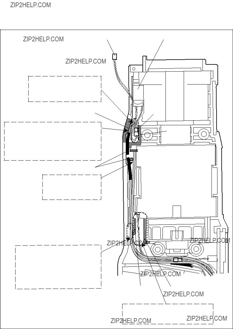
Wiring around Controller
Fig.
rib (A)
Route Lead wires from Switch unit (for rotation reverse) between rib (A) and rib (C).
rib (B)
Route Lead wires from Switch unit (for Trigger) between rib (B) and rib (C).
rib (C)
Switch
Route Lead wires (orange, white, blue) from Controller to Stator between the two pins.
pin
Put Connectors and the slack portion of Lead wires in the space
between ribs (A)- (B)- (C) and pins- rib (D)- boss.
rib (D) Connector
 boss
boss
Controller
Power supply circuit
Put Connector and Lead wires from Controller to Power supply circuit between the ribs on Controller.
Connector
Put Power supply circuit
with Sponge on Housing (L) side.
Sponge
Put Lead wires from Controller to Power supply circuit on the groove on Controller.
groove
 rib
rib
RF unit
Terminal
Install Receptacles on Terminal as illustrated below.
Lead wire (red) 

 Terminal
Route Lead wires that connects Power supply circuit with RF unit between three pins as illustrated below.
pin
pin
P 12/ 13
 Wiring diagram
[2] Wiring around Stator
Fig.
Put Connectors and the slack portion of Lead wires in the space between rib (E) and the inside wall of Housing.
Route the following Lead wires from Controller between rib (E) and the inside wall of Housing: *Lead wires to LED circuit
*Lead wires to Switch unit (for Clutch)
At this time, place these Lead wires so that the tape is positioned beside Printed wiring board.
tape
Route three Lead wires (orange, white, blue) from Controller to Stator between the pin and Stator.
rib (E)

 Printed wiring board
  pin
pin
Stator
Lead wire holder 
First, put the following Lead wires from Controller in place:
*Lead wires to LED circuit
*Lead wires to Switch unit (for Clutch) Then, fix Lead wires (orange, white, blue) from Controller to Stator with this Lead wire holder.
Route six Lead wires (orange, black, white, yellow, blue, red) from Controller to Stator between rib (F) and rib (G).

 Wiring diagram
P 13/ 13
Wiring of Lead wires of LED circuit
Fig. 4