CONCEPT AND MAIN APPLICATIONS
Model AR410HR is a pneumatic screwdriver powered by high pressure air. Drives coil type collated drywall screws exactly to depth and fastens plasterboard securely to wood/metal drywall stud.
Its main benefits are:
 Compact body for easy handling and high maneuverability
 High power allowing to fasten plasterboard securely to metal stud of even 0.8mm thick steel plate without unseated screw
 Optimum for operation in job sites among residential area thanks to low-noise air exhaust
 Rigid contact arm enabling to make fine finish constantly
 Specification
*1: Screws can be driven one after the other continuously first by pulling Trigger then by bumping Contact arm against workpiece with the Trigger being pulled.
*2: One screw is driven first by pushing Contact arm against workpiece, then by pulling Trigger with the Contact arm kept pushed; screw cannot be driven when the steps are reversed. Another one can be driven by releasing Trigger, then by repeating the steps; however, cannot be driven if Trigger is not released before repetition of the steps.
 Standard equipment
Note: The standard equipment for the tool shown above may vary by country.
 Optional accessories
Plastic sheet collated drywall screws (coil type)
[3.5mm shank diameter: 25, 28, 41mm; 3.8mm shank diameter: 25, 28, 32, 41mm] Air hose
Air leak repair set
P 2/20
 Repair
CAUTION: Disconnect the air hose from the machine and then remove remaining screws for safety before repair/ maintenance in accordance with the instruction manual!
[1] NECESSARY REPAIRING TOOLS
[2] LUBRICATIONS
Apply ISOFLEX NB52 to the portions designated with the white arrow, and apply lubricant VG32 to the portions designated with black arrow, to protect parts and product from unusual abrasion.
Drive section
Inlet section
Air motor
Nail feed piston section
P 3/20
 Repair
[3] DISASSEMBLY/ASSEMBLY
[3]-1. Fastening Torque for Bolts ans Scerws
Tighten the bolts and scerws to the required fastening torque.
* Apply a little amount of Loctite 242 or Three Bond 1321/1342 to the threaded portion of 77 Plug.
P 4/20
 Repair
[3] DISASSEMBLY/ASSEMBLY
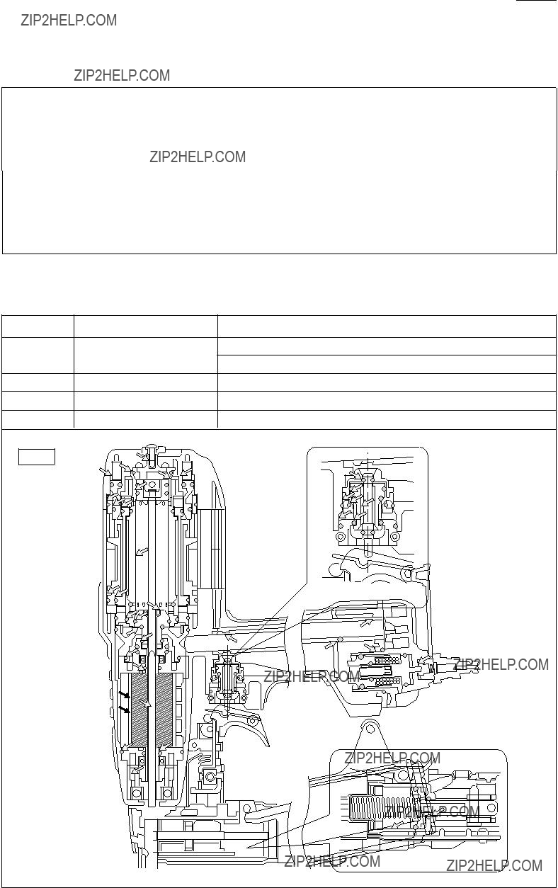
[3]-2. Top Cap Section
DISASSEMBLING
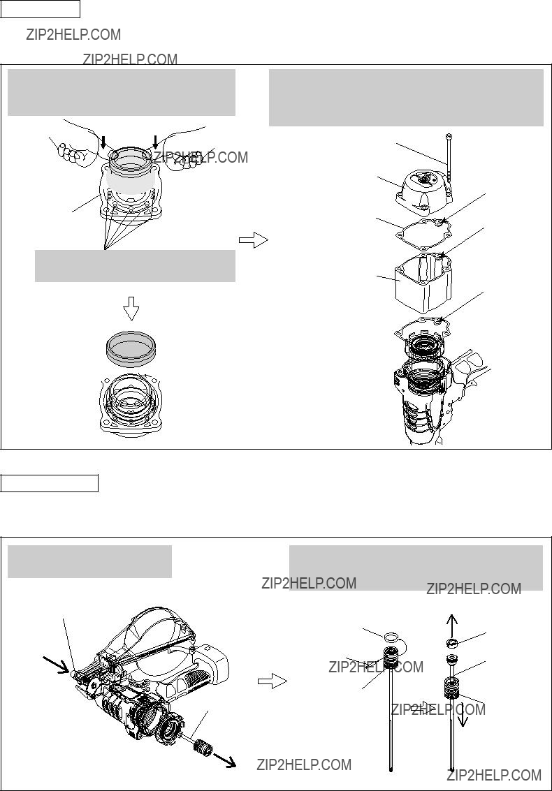
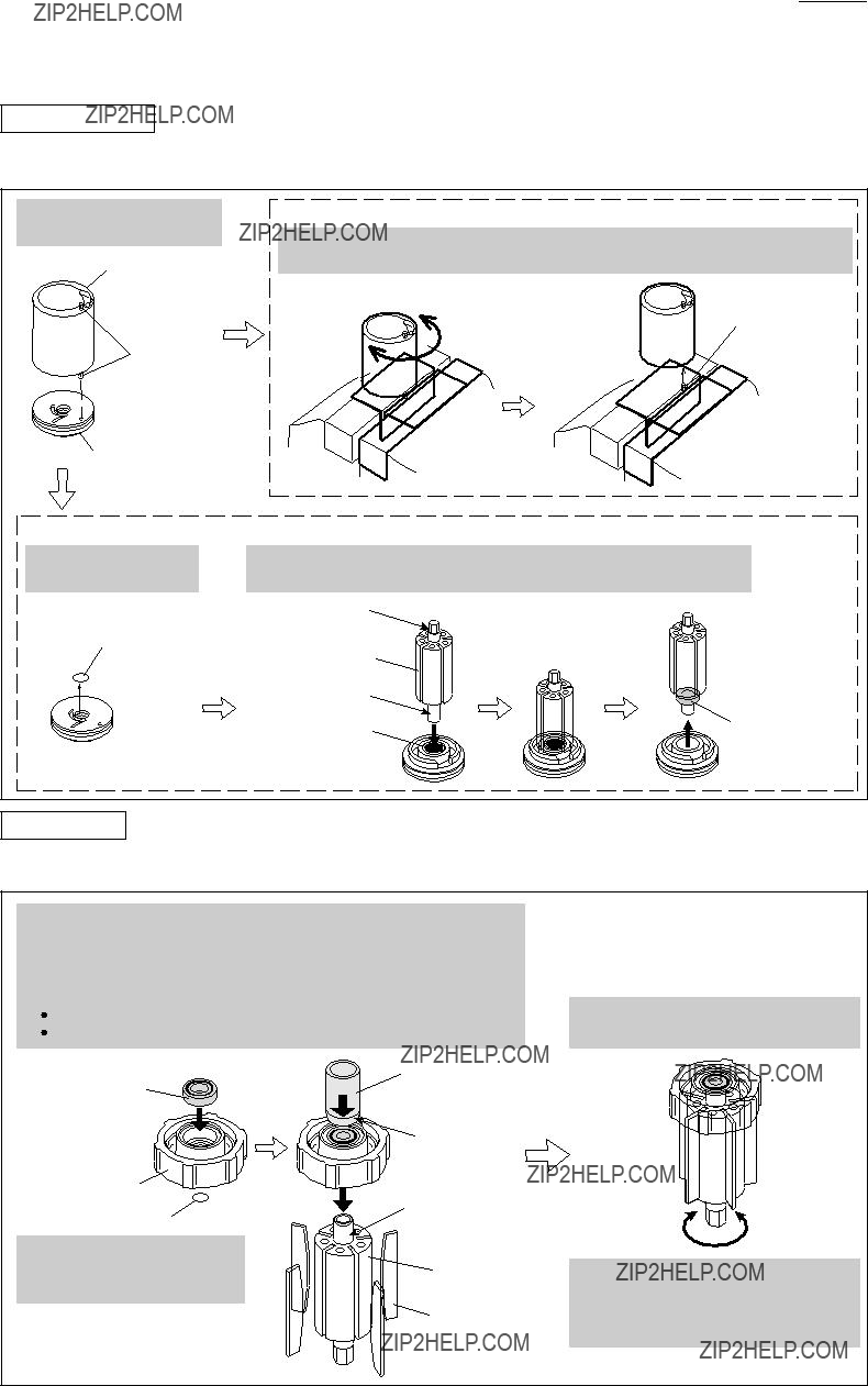
1)After removing Top cap and Top cap spacer from Housing, remove Head valve and Cylinder stay from Top cap using air duster to blow air into the space between Top cap and Head valve using air pressure. (Fig. 3)
2)Remove Knob from Top cap, then disassemble the other parts from Top cap as illustrated in Fig. 4.
Fig. 3
1.By removing four M5x80 Hex socket head bolts using 1R299, separate Top cap, Top cap spacer and Top cap gasket from Housing. Then remove Top cap and the other Top cap gasket from
Top cap spacer.
2.Turn Top cap upside down, then press down Head valve and Cylinder stay firmly into Top cap with your palm to make the air pressure as possible.
While pressing down Head valve and Cylinder stay, insert nozzle of air duster into the hole of Top cap.
M5x80
Hex socket 
 head bolt
(4 pcs)
Top cap
Top cap spacer 
Nozzle of air duster
Top cap
Insert nozzle of air duster into this hole.
Head valve
Cylinder stay
Top cap gasket 
3.By blowing air into the space between Top cap and Head valve through the hole, Cylinder stay and Head valve can be separated from Top cap.
Cylinder stay 

Head valve 
Fig. 4
By removing M4x8 Hex socket button head bolt and Knob,
the inner parts can be removed from Top cap as illustrated below.
P 5/20
 Repair
[3] DISASSEMBLY/ASSEMBLY
[3]-2. Top Cap Section
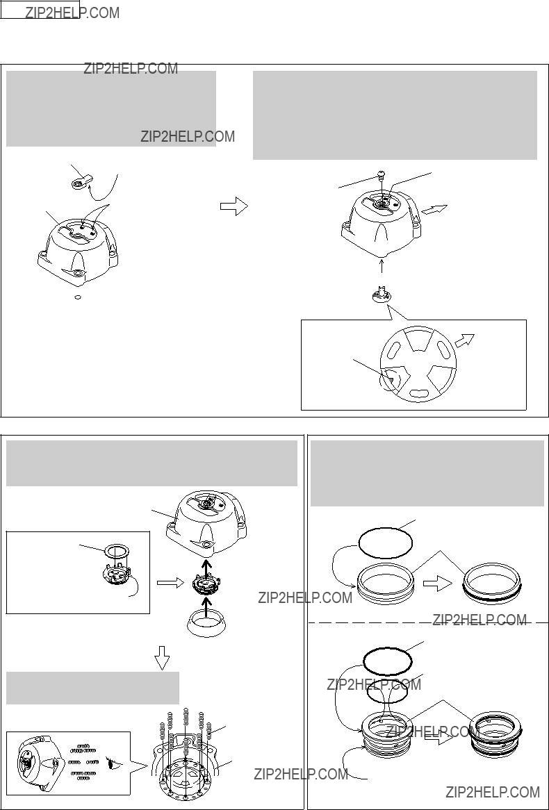
ASSEMBLING
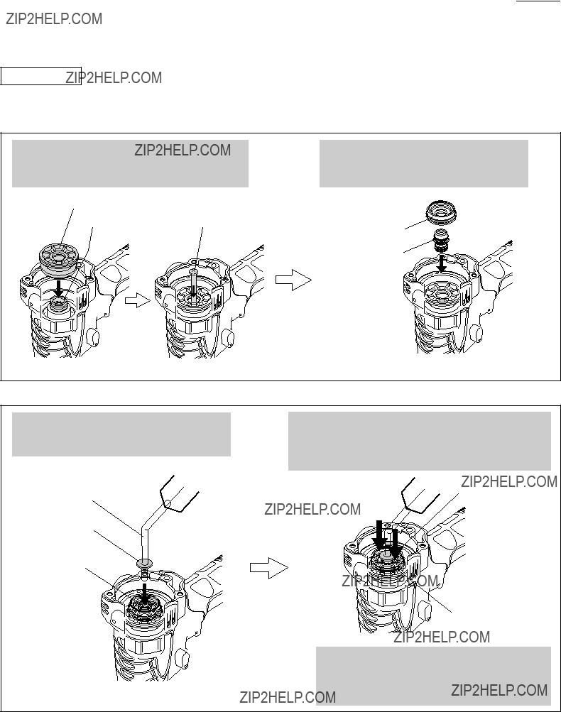
1)Assemble Top cap section as described in Figs. 5, 6.
2)Assemble O rings to Cylinder stay and Head valve as described in Fig. 7.
Fig. 5
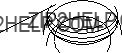
Set Knob on Top cap, with the protrusion on its back fitting in either click-stop concave portions on Top cap.
Then assemble O ring 6 to the insertion hole for Change valve.
Knob protrusion
 O Ring 6
Assemble Conical compression spring 10-15 to Top cap with the small end on Change valve side.
Then assemble Change valve to Top cap.
Note: When assembling Change valve to Top cap, place the notch on the front side of Top cap as illustrated below so that Change valve can engage with Knob easily.
Knob
M4x8 Hex socket button head bolt
Rear side
Front side

Conical compression
 spring 10-15
Change valve 

Rear side
notch
Front side 
Fig. 6
After mounting O ring 22 and Flat washer 19 on Rear cushion, assemble Rear cushion to Top cap, then assemble Seal ring to Top cap.
Top cap
Flat washer 19
Rear cushion 


O Ring 22 
Seal ring 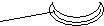
Set Compression spring 4 (8 pcs)
in the big diameter holes of Top cap.
Compression spring 4
Top cap
Fig. 7
Before assembling Cylinder stay and Head valve to Top cap, mount O rings to them as illustrated below, then apply such an amount of IDOFLEX grease that they are covered with a thick layer of the grease.
O Ring 54
Cylinder stay
O Ring 47
O Ring 40
Head valve
 O Ring 45
P 6/20
 Repair
[3] DISASSEMBLY/ASSEMBLY
[3]-2. Top Cap Section
ASSEMBLING
3)Assemble Head valve and Cylinder stay to Top cap (left in Fig. 8); assembling of Top cap section is now completed. Then assemble Top cap section, Top cap spacer and Top cap gasket to Housing as illustrated on right in Fig. 8.
Fig. 8
Top cap spacer and two Top cap gaskets are directional when assembled to Housing.
Make sure that the holes A, B, C are aligned with the hole of Housing.
M5x80 Hex socket head Bolt (4 pcs)
Top cap section
A
Top cap spacer
C
Top cap gasket 
Housing


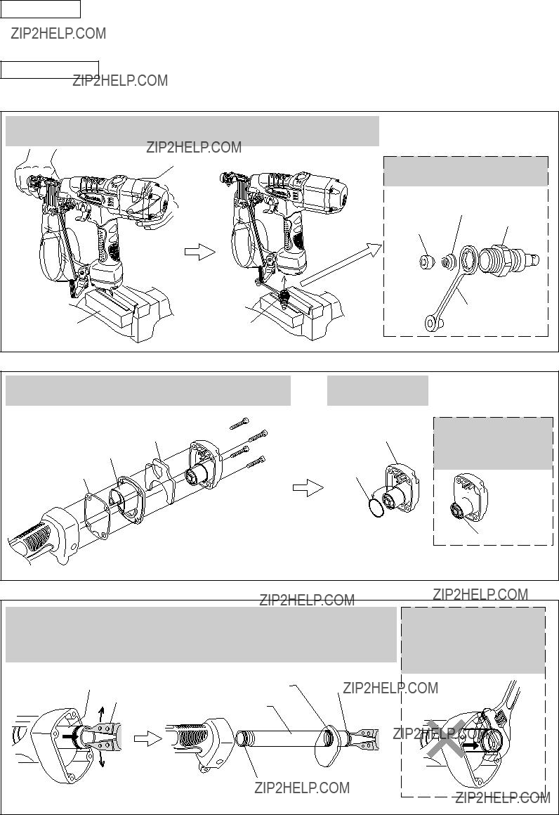
[3]-3. Driver Bit
DISASSEMBLING
1)Disassemble Top cap and Top cap spacer from Housing as described on left in Fig. 3.
2)Disassemble Driver bit as described in Fig. 9.
Fig. 9
Remove Driver bit by pushing it from Driver guide complete side.
Driver guide complete
After removing Rubber ring 19 (white), pull off Pin 3. Main piston and Piston cap can now be removed
as illustrated below.
P 7/20
 Repair
[3] DISASSEMBLY/ASSEMBLY
[3]-3. Driver Bit
ASSEMBLING
Do the reverse of the disassembling steps. Note: Be careful with the following:
 Piston cap is directional when assembled to Driver bit. (Fig. 10)
 Align Driver bit with the hole of Carrier complete when assembling Driver bit to the machine. (Fig. 11)
 Driver bit
Hole for Driver bit insertion
[3]-4. Cylinder Section
DISASSEMBLING
1)Disassemble Top cap and Top cap spacer from Housing as described on left in Fig. 3.
2)Disassemble Cylinder section as described in Fig. 12.
Fig. 12
P 8/20
 Repair
[3] DISASSEMBLY/ASSEMBLY
[3]-4. Cylinder Section
DISASSEMBLING
3)Sealing rings can be removed from Outer cylinder, Separator, Cylinder, Cushion guide and Front cushion assembly as illustrated in Fig. 13.
4)From Outer cylinder, remove Cylinder seal as described in Fig. 14.
Fig. 14
Remove Cylinder seal from Outer cylinder by levering it up with a slotted screwdriver.
Cylinder seal
Outer cylinder
Do the reverse of the disassembling steps. (Figs. 14, 13, 12, 3)
[3]-5. Air Motor Section
DISASSEMBLING
1)Disassemble Top cap and Top cap spacer from Housing as described on left in Fig. 3.
2)Disassemble Cylinder section as described in Fig. 12.
3)Disassemble Air motor section from Housing, then remove Internal spur gear 44 as described in Fig. 15.
Fig. 15
Disassemble Air motor section from the machine by hitting the end surface of Housing with mallet.
Then remove Internal spur gear section.
After removing Spur gear 10 (5 pcs), remove the assembly of Carrier complete and
Ball bearing 6001LLU from Internal spur gear 44 by pushing it in the direction of the arrow.
Outer separator
Air motor section
 Flat washer 15
Internal spur gear section
Spur gear 10
 Internal spur gear 44
Carrier complete
 Ball bearing 6001LLU
Do not remove the assembly by pushing it in the opposite direction, or the teeth of
Internal gear 44 will be damaged.
P 9/20
 Repair
[3] DISASSEMBLY/ASSEMBLY
[3]-5. Air Motor Section
DISASSEMBLING
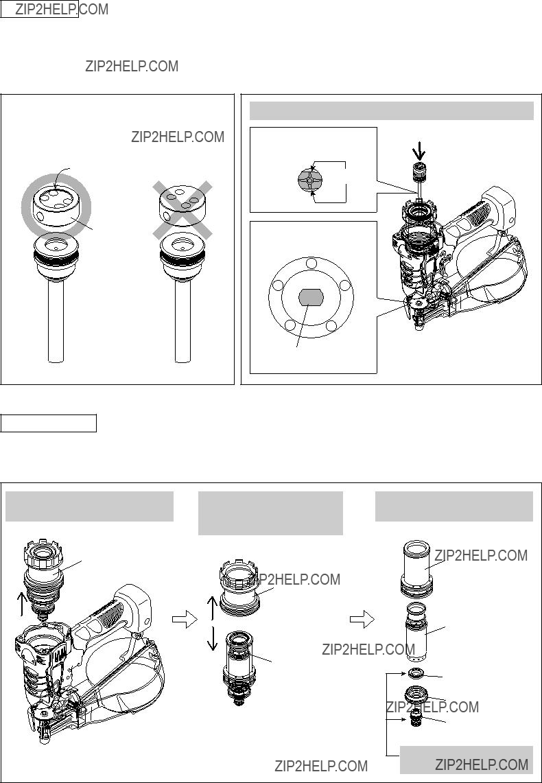
4)Disassemble Air motor section and remove Rotor and Upper drum cap as described in Fig. 16.
5)Rotor can be disassembled as described in Fig. 17.
Fig. 16
Remove Outer separator, Inner separator and Spur gear 21 from Air motor section.
Outer separator
Inner separator
Upper drum cap
 Lower drum cap
 Spur gear 21
Remove O rings from Outer separator and Inner separator.
 O Ring 45
Outer separator
 O Ring 31.5
 O Ring 17
 Inner separator

 O Ring 16
Remove Rotor by tapping the drive-end of Rotor shaft.
Upper drum cap
Rotor
Drum
Lower drum cap
In this step, Ball bearing 689ZZ still remains in Lower drum cap.
Damaged or worn Blades can be replaced in this step.
Note: Five Blades have to be replaced simultaneously.
Blade
Rotor
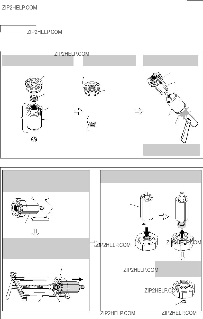
Remove Rotor from Upper drum cap using 1R045 and 1R346.
In this step, Ball bearing 689ZZ still remains in Upper drum cap.
Upper drum cap
Ball bearing 689 ZZ can be removed from Upper drum cap using Rotor as illustrated below.
Hexagonal end of Rotor shaft 

Rotor
Round end of Rotor shaft 

Ball bearing
689 ZZ 
Upper drum cap 
O Ring 9 can be removed from the opposite side of Ball bearing 689ZZ.
P 10/20
 Repair
[3] DISASSEMBLY/ASSEMBLY
[3]-5. Air Motor Section
DISASSEMBLING
6) Spring pin 2.5-5 and Ball bearing 689ZZ can be removed as described in Fig. 18.
Fig. 18
Lower drum cap
Removing Ball bearing 689ZZ from Lower drum cap
Remove O ring 9 from Lower drum cap.
Turn Lower drum cap upside down, then pull off Ball bearing 689ZZ using Rotor as illustrated below.
ASSEMBLING
1) Assemble Rotor to Upper drum cap as described in Fig. 19.
Fig. 19
It may be a little bit tight to rotate Rotor. However, this is not a trouble.
The tightness is caused by O ring 9 correctly set in Upper drum cap.
P 11/20
 Repair
[3] DISASSEMBLY/ASSEMBLY
[3]-5. Air Motor Section
ASSEMBLING
2) Assemble Upper drum cap to Drum as described in Fig. 20.
Fig. 20
3) Assemble Lower drum cap to Drum as described in Fig. 21.
Fig. 21
1.Assemble Ball bearing 689ZZ to Lower drum cap using 1R027 and arbor press.
Set Drum on Lower drum cap, with Spring pin 2.5-5 of Drum fitting in the corresponding insertion hole of Upper drum cap.
Ball bearing 689ZZ
Lower drum cap
2.Support Drum with 1R027 at the Ball bearing 689ZZ of Lower drum cap. Then apply another 1R027 to the Ball bearing 689ZZ in Upper drum cap, and firmly assemble Upper drum cap and Lower drum cap to Drum by pressing down Upper drum cap and Drum using arbor press until they stop.
1R027


 Upper
Upper
drum cap
1R027
3.Assemble Spur gear 21 to the hexagonal end of Rotor shaft protruding from Lower drum cap.
4.Assemble Internal spur gear section to Air motor section, with the ribs of Internal spur gear 44 fitting in the cut portion of Lower drum cap.
P 12/20
 Repair
[3] DISASSEMBLY/ASSEMBLY
[3]-5. Air Motor Section
ASSEMBLING
4) Assemble Air motor section to Housing as illustrated in Figs. 22, 23.
Fig. 22
Driver bit
Hole A: insertion hole for Driver bit
Carrier complete
Internal gear 44 
Ribs A: with larger intervening width
1R273
[Top view]
Carrier complete
Hole A
Ribs A
1. First, for easy assembling, make the following adjustment: Insert Driver bit into Hole A of Carrier complete.
Then, by turning Driver bit, set Hole A vertical (or horizontal) to Ribs A of Internal gear 44.
Note: Ribs A cannot be seen when assembling Air motor section to Housing although alignment of Ribs A with Rib B (See Fig.23) of Housing is required.
This adjustment will be able to know the position of Ribs A from that of Hole A.
2.Hold Housing over Air motor section on 1R273.
In order to fit Rib B (located on Grip side inside Housing) in Ribs A, while watching Hole A through Hole B of Housing, turn Housing or Air motor section so that Hole A is positioned vertical (or horizontal) to Grip.
Put Housing down over Air motor section until it stops.
3.Make sure that Air motor section is properly assembled to Housing by measuring the depth indicated in the illustration below.
The depth will be approximately 43.5mm if properly assembled.
Rib B: located on the inside surface
of Housing end, positioned on Grip side, widest of the four
Housing
Grip
Hole B:
Hole for Driver bit on the end surface of Housing
Hole A
Ribs A
 Upper
Upper
drum cap
Housing
Upper drum cap
approx.
43.5mm
 1R273
1R273
P 13/20
 Repair
[3] DISASSEMBLY/ASSEMBLY
[3]-5. Air Motor Section
ASSEMBLING
5)Before assembling Cylinder section to Housing, make sure if Air motor section is properly assembled to Housing by doing the test as described in Figs. 24, 25.
Fig. 24
Mount Inner separator and Outer separator, then insert 4 Tapping screw for preventing air leakage.
Mount O rings on Front cushion assembly and Cushion guide. (Refer to Fig. 13.) Then mount them on Outer separator.
Attach a Flat washer of proper size to nozzle of air duster for preventing air leakage. Then insert the nozzle into Front cushion.
Firmly pressing down Cushion guide and Flat washer with fingers, blow air into the machine.
Rotor will rotate with humming if Air motor section is properly assembled to Housing.
air duster
Flat washer of proper size
Front cushion
Flat washer
Cushion guide
If Rotor does not rotate with noise of air moving through and out of the machine, insert Driver bit into Rotor and rotate Rotor by turning Driver bit. Then do this check again.
6)Assemble Cylinder section to Housing. (Fig. 12)
7)Assemble Top cap section to Housing as illustrated on left in Fig. 3.
P 14/20
 Repair
[3] DISASSEMBLY/ASSEMBLY
[3]-6 Magazine Section
DISASSEMBLING
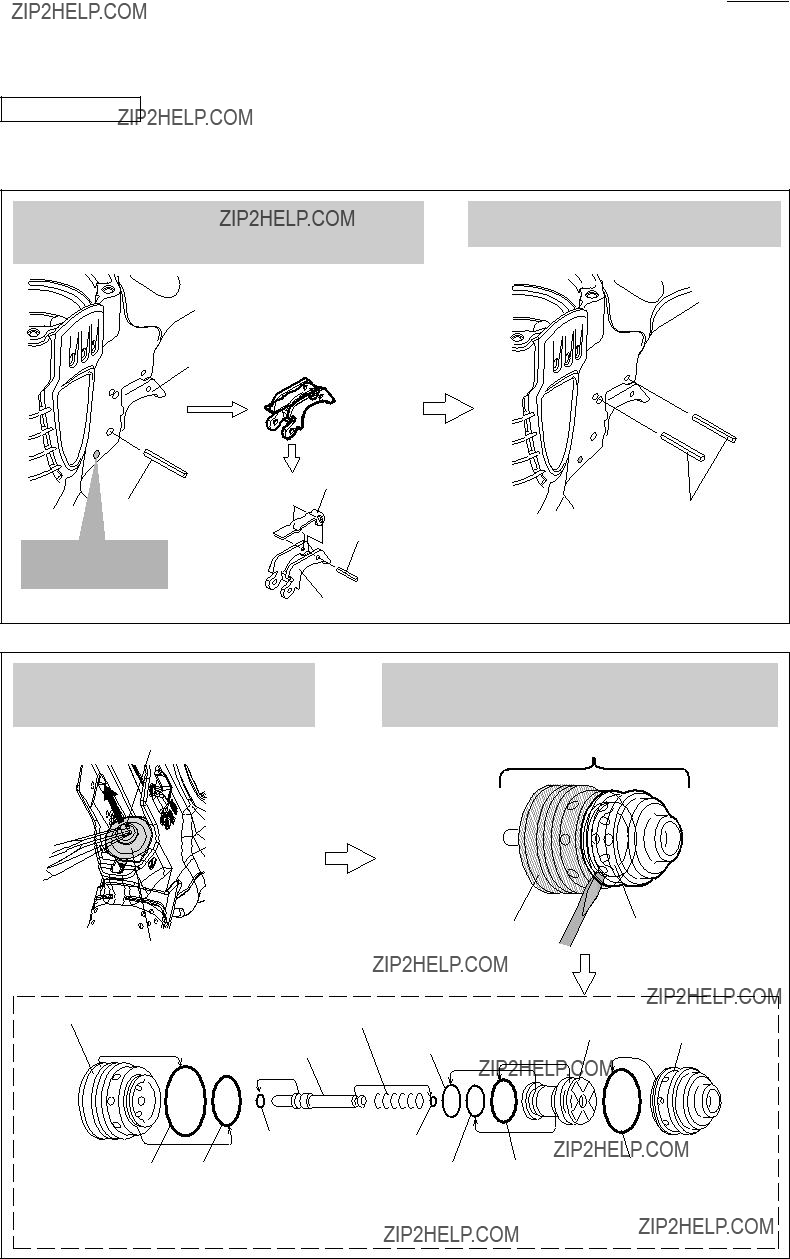
1)Separate Magazine section from Housing as described in Fig. 26.
2)The Magazine section can be disassembled as described in Fig. 27.
Fig. 26
Magazine section can be separated from Housing by removing
M5x28 Hex socket head bolt, Flat washer 5, M5 Hex nut and Hook.
M5x28 Hex socket head bolt
Flat washer 5
Magazine section
Hook
M5 Hex nut
Fig. 27
Stop ring E5 is the stopper for Pin 5 (hinge pin).
Therefore, by removing this Stop ring using slotted screwdriver from the rear of Magazine complete, Pin 5 can be removed from Magazine complete, and consequently, Magazine cap complete is separated from Magazine complete.
Pin 5
Stop ring E5
Magazine complete
Stop ring E5
Magazine cap complete
P 15/20
 Repair
[3] DISASSEMBLY/ASSEMBLY
[3]-7. Trigger Valve Section
DISASSEMBLING
1)In order to separate Trigger valve section from Housing, first, remove Spring pin 3-28 (3 pcs )and Trigger. (Fig. 28)
2)Pull off Trigger valve section from Housing, then disassemble it as described in Fig. 29.
Fig. 28
Remove Trigger by removing Spring pin 3-28 with 1R268. Trigger can be disassembled by removing Spring pin 2.5-16 with 1R267.
Using 1R268, remove Spring pin 3-28 (2 pcs) securing Trigger valve section to Housing.
Trigger
Do not remove
this Spring pin 3-28.
Trigger
Fig. 29
Remove Trigger valve section from Housing by pinching Trigger valve stem with pliers, then pulling it in the direction of the arrow.
Trigger valve stem
Trigger valve section can be disassembled by levering off Trigger valve guide from Trigger valve case using a slotted screwdriver.
Trigger valve section
Trigger valve stem
P 16/20
 Repair
[3] DISASSEMBLY/ASSEMBLY
[3]-7. Trigger Valve Section
ASSEMBLING
1)Mount O rings to Pilot valve as described in Fig. 30.
2)Assemble Trigger valve section. (Refer to the bottom illustration in Fig. 29.)
When assembling Trigger valve guide to Trigger valve case, push it toward Trigger valve case until it snaps in place.
Fig. 30
Two different kinds of O rings of size 8 are mounted on Pilot valve:
A O Ring 8 (213984-5), of Nitrile rubber,
with one side painted white for identification B O Ring 8 (213985-3), of Urethane rubber
Do not confuse these two O rings because they are not interchangeable, and be sure to mount them in position as illustrated on right.
3) Set Trigger valve section in Housing as illustrated in Fig. 31.
Fig. 31
Housing
Trigger valve section
4) Secure Trigger valve section to Housing with Spring pin 3-28 as described in Fig. 32
Fig. 32
2.Then insert Spring pin 3-28 from the opposite side, and fit its hole over the stepped end of 1R268.
P 17/20
 Repair
[3] DISASSEMBLY/ASSEMBLY
[3]-8. Adjuster, Contact Arm Assembly
DISASSEMBLING
1)Separate Driver guide section from Housing, then separate Contact arm assembly from Driver guide section. (Fig. 33)
2)Disassemble Contact arm assembly as described in Fig. 34.
Fig. 33
Contact arm assembly
Contact arm cover
Driver guide section
Fig. 34
Put Contact arm assembly on 1R217 or the like, then remove Spring pin 2-14 (used as a stopper for Adjust shaft) with 1R266. Adjust shaft can now be removed by turning Adjuster complete. Note: Be careful not to lose Steel ball 2.3 and
Compression spring 2.
Contact arm can be removed from Stopper by turning Adjust piece 90 degrees then by pulling up through the window of Stopper.
Adjust piece
Contact arm
Steel ball 2.3 Compression spring 2
Adjuster complete
Spring pin 2-14
P 18/20
 Repair
[3] DISASSEMBLY/ASSEMBLY
[3]-8. Adjuster, Contact Arm Assembly
DISASSEMBLING
3) The parts of Chuck portion can be disassembled from Contact arm as illustrated in Fig. 35.
Fig. 35
Washer
ASSEMBLING
1)Assemble the parts of Chuck portion to Contact arm as described in Fig. 36.
2)Then do the reverse of the disassembling steps. (See Figs. 34, 33.)
Fig. 36
Assemble two Chucks and Contact top to Contact arm with the open sides of the four parts on the same side. If assembled wrong way, screws cannot be fed.
open side
Contact arm
Insert Pin 3.5 through Contact top, Contact arm,Chucks and Torsion spring 4, then fix them with Washer as illustrated below.
P 19/20
 Repair
[3] DISASSEMBLY/ASSEMBLY
[3] -9. Driver Guide, Feed Piston
DISASSEMBLING
1) Disassemble Driver guide section and Feed piston as described in Figs. 37, 38, 39.
Fig. 37
Remove Contact arm cover from Housing by unscrewing M5x16 Hex socket head bolt.
Because two Compression springs are mounted in Driver guide complete, remove Retaining ring R-24 while pressing Cup washer firmly.
Slowly remove Cup washer so that two Compression springs do not pop out. Then remove Compression spring 10, Compression spring 9 and Rubber ring 14.
Compression
M5x16 Hex socket head bolt
spring 10
Cup washer
Compression spring 9
Remove Feed piston from Feeding claw.
Note:
Be careful not to lose Compression spring 3 mounted between Feed piston and Feeding claw.
Remove Urethane ring 3 from Pin 4 and Lock pin.
Urethane ring 3
Lock pin
Urethane ring 3
P 20/20
 Repair
[3] DISASSEMBLY/ASSEMBLY
[3]-9. Driver Guide, Feed Piston
ASSEMBLING
Do the reverse of the disassembling steps. (Refer to Figs. 39, 38, 37.)
[3]-10. Inlet Cap, Plug
DISASSEMBLING
Disassemble Plug and Inlet cap as described in Figs. 40, 41, 42.
Fig. 40
Clamp the hex portion of Plug in vise. Then, by turning the machine clockwise,
Plug section can be removed from the machine.
Plug section can be disassembled as illustrated below.
Comical compression spring 5-10
Fig. 41
By unscrewing four M5x30Hex socket head bolts,
four parts can be removed from Housing as illustrated below.
Inlet cap with Adjust cap Filter 

Inlet cap spacer Inlet cap gasket
M5x30 Hex socket head Bolt (4 pcs)

 Housing
Remove O ring 25 from Inlet cap.
Inlet cap with
Adjust cap
O Ring 25
[Caution]
Do not turn Adjust cap because it is
factory adjusted.


 Inlet cap
Adjust cap
Pipe 13 can be removed from Housing by holding the inside of the Pipe with 1R003 then by pulling off Pipe 13 together with Inlet filter.
If it is difficult to remove Pipe 13 using 1R003, remove by striking the end surface of Grip with mallet.
[Caution]
Do not clamp the outside of Pipe 13, or its outer surface will be scratched, causing air leakage.
O Ring 14 [thin] Inlet filter (213162-7)


 Retaining ring


 Cup washer