CONCEPT AND MAIN APPLICATIONS
Model HK1820 has been developed as the successor model of HK1810, featuring vibration absorbing handle additionally to the same compact and lightweight design as the predecessor model.
Also features the chuck adapted for SDS-PLUS bits.
 Specification
Note: The standard equipment for the tool shown above may differ by country.
 Optional accessories
P 2/17
 Repair
CAUTION: Remove the bits from the machine for safety before repair/maintenance in accordance with the instruction manual!
[1] NECESSARY REPAIRING TOOLS
[2] LUBRICATION
Apply the following lubricants to protect parts and product from unusual abrasion: *Makita grease N.No.1 to the portions designated with black triangle
*Makita grease R.No.00 to the portions designated with gray triangle *Makita grease N.No.2 to the portions designated with white triangle
P 3/17
 Repair
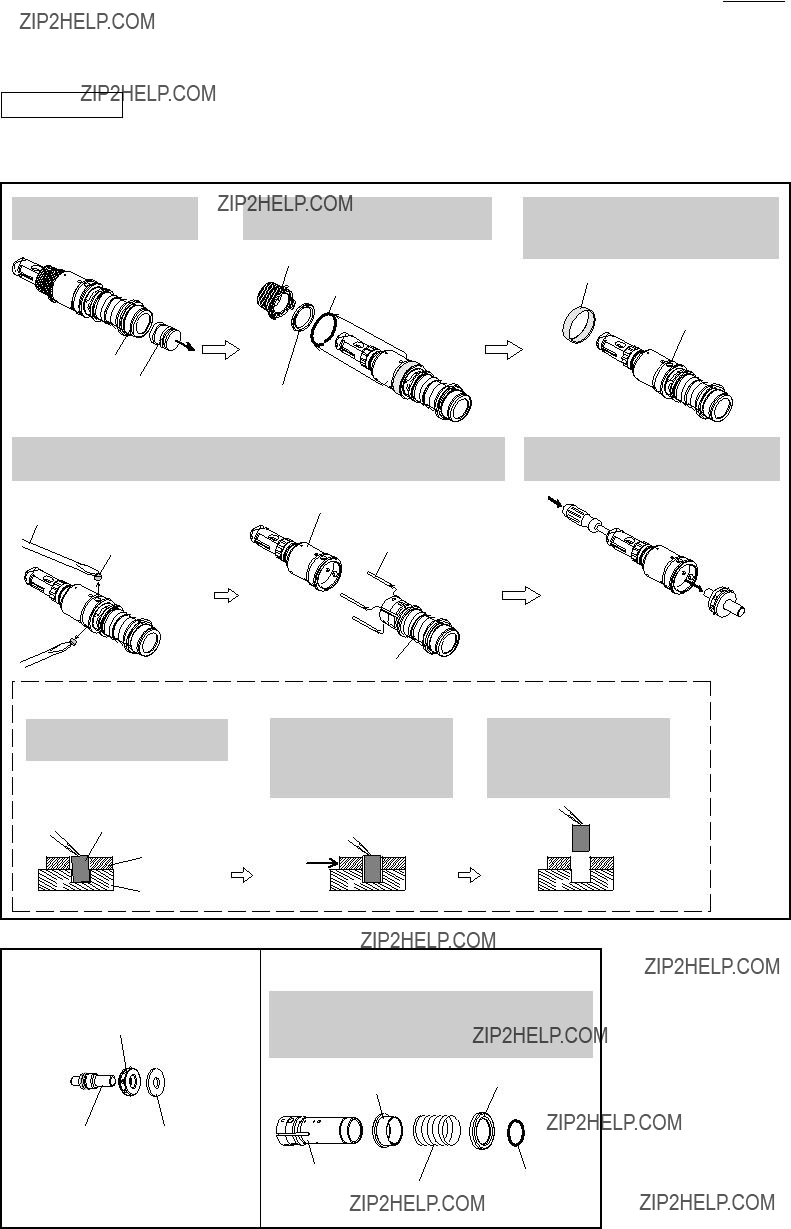
[3] DISASSEMBLY/ASSEMBLY
[3] -1. Chuck Section
DISASSEMBLY
Disassemble the Chuck section as described in Figs. 2 and 3.
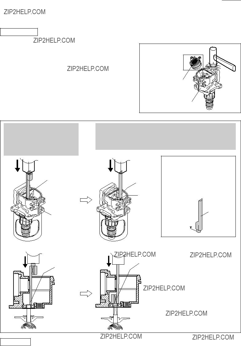
Fig. 2
1)For easy repairing, separate Handle section and stand the machine on a workbench as illustrated below on right. Note: Remove Compression spring 14 before standing the machine if it is left on Crank housing complete.
M5x20 Pan head screw (2 pcs)
2)Remove Cap 38 with slotted screwdriver.
Cap 38
5)Remove Steel ball 7 (2 pcs) using screwdriver magnetized with 1R288 while pressing down Ring 21.
Screwdriver magnetized with 1R288
Steel ball 7 (2 pcs)
Ring 21

3)Remove Ring spring 19 with 1R212 and 1R003 while pressing down Chuck cover.
1R212 and 1R003
Ring spring 19 Chuck cover
Note:
Be sure to press down Chuck cover or it will pop off due to the pressure of Compression spring 42.
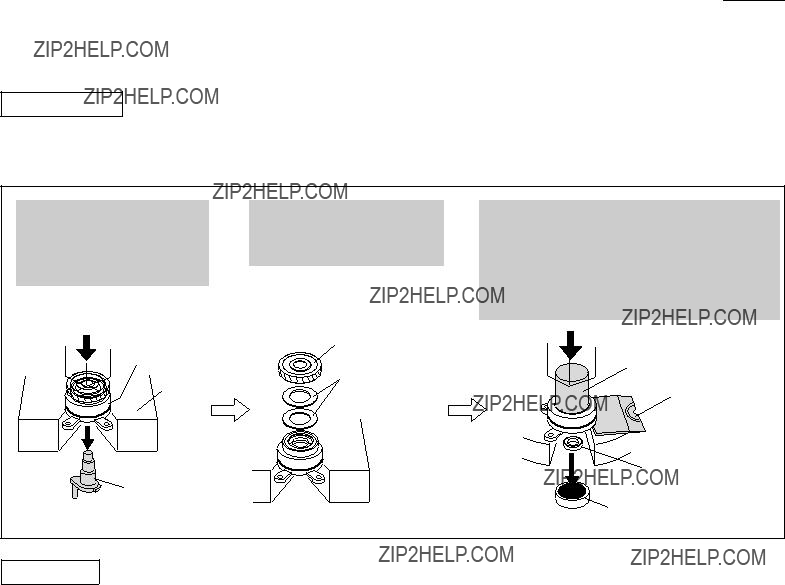
6)The parts inside Change ring can be removed.
 Ring 21

 Guide washer
Conical compression spring 21-29

 Steel ball guide
4)Remove Chuck cover and Compression spring 42.
Compression spring 42
Chuck cover
7)Change ring can now be removed.
Change ring
DISASSEMBLY
Do the reverse of the disassembling steps.
P 4/17
 Repair
[3] DISASSEMBLY/ASSEMBLY
[3] -2. Barrel, Tool Holder, Cylinder Section
DISASSEMBLY
1)Disassemble the Chuck section as described in Figs. 2, 3.
2)Disassemble Tool holder, Ring 25 and Cylinder section from Barrel as described in Figs. 4, 5, 6.
Fig. 4
Fig. 5
Remove Steel ball 4.8 (3 pcs) from each hole of Ring 25 with slotted screwdriver.
Screwdriver magnetized with 1R288
Ring 25
Steel ball 4.8 (3 pcs)
Barrel section can now be separated from Crank housing complete by unscrewing
four M5x25 Hex socket head bolts with 1R229.
Tool holder

 Barrel
 Turn counterclockwise. 1R229
M5x25 Hex socket head bolt (4 pcs)
Strike Tool holder against work bench.
Tool holder, Ring 25 and Cylinder section can now be removed from Barrel. Remove O ring 48 from Barrel.
P 5/17
 Repair
[3] DISASSEMBLY/ASSEMBLY
[3] -2. Barrel, Tool Holder, Cylinder Section
DISASSEMBLY
3)Separate Tool holder from Cylinder section as described in Fig. 7.
4)Disassemble Impact bolt and Cylinder section as described in Fig. 8.
Fig. 7
1.Pull out Striker from Cylinder section.
Cylinder section Striker
2.Remove ring 25, Urethane ring 26 and Ring spring 37 from Cylinder.
Ring 25
Ring spring 37
Urethane ring 26
3.By removing Ring 39, you can see Pin 6 (3 pcs) that join Tool holder with Cylinder.
Ring 39
Pin 6 (3 pcs)
4.By removing Pin 6, Tool holder can be separated from Cylinder section. Remove Rod 2.5 (3 pcs) from the grooves of Cylinder.
5.Push out Impact bolt section from Cylinder section using screwdriver.
Impact bolt section
Cylinder section
Note: Pin 6 can be removed as described below if it is difficult to remove.
1.Apply magnetized screwdriver to Pin 6.
Screwdriver, magnetized with 1R288  Pin 6
Pin 6
2.Align the through hole of Tool holder with that of Cylinder by pushing Tool holder.
3.Remove Pin 6 using magnetized screwdriver when the two holes are aligned.
Fig. 8
After removing O Ring 26, the following parts Rubber ring 13can be removed from Cylinder:
Cup washer 29, Compression Spring 32, Ring 29
P 6/17
 Repair
[3] DISASSEMBLY/ASSEMBLY
[3] -2. Barrel, Tool Holder, Cylinder Section
ASSEMBLY
Do the reverse of the disassembling steps.
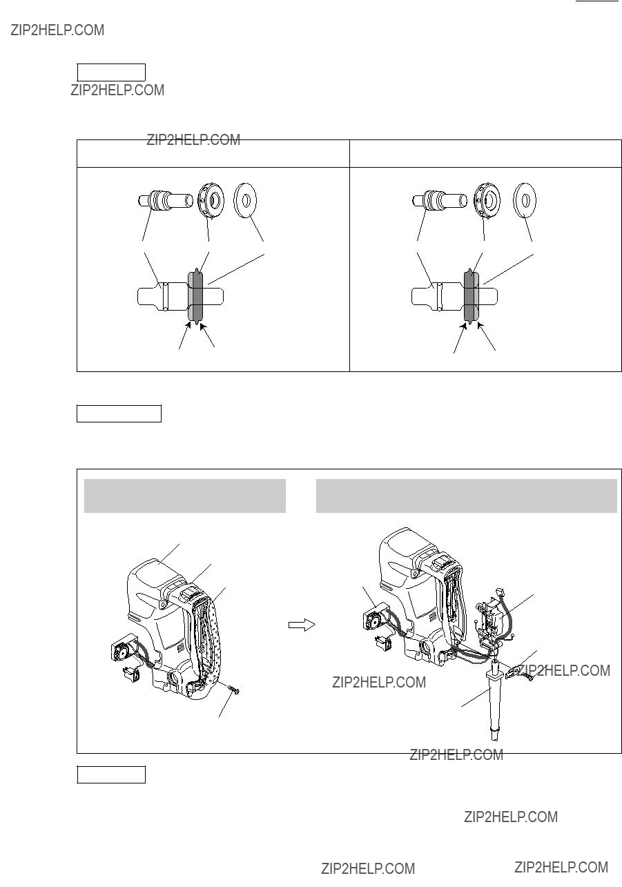
Note: Rubber ring 13 is directional when assembled to Impact bolt.
Be sure to assemble as illustrated to left in Fig. 9.
Fig. 9
[3] -3. Electrical Parts in Handle Section
DISASSEMBLY
1)Disassemble Handle section as described in Fig. 2
2)The electrical Parts can be replaced as described in Fig. 10.
Fig. 10
1.Disassemble Handle cover from Handle by unscrewing 4x18 tapping screw.
2.Disconnect all the Lead wires from Switch.
Controller, Switch and Power supply cord can now be replaced.
Handle base
4x18 Tapping screw (1 pc)
ASSEMBLY
Do the reverse of the disassembling steps.
P 7/17
 Repair
[3] DISASSEMBLY/ASSEMBLY
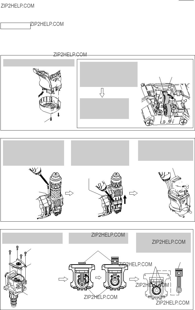
[3] -4. Motor Section
DISASSEMBLY
1)Disassemble Handle section as illustrated in Fig. 2
2)Separate the contact of Carbon brushes from Commutator as described in Fig. 11.
3)Disassemble Crank housing complete from Motor housing as illustrated in Fig. 12.
4)Remove Piston from Crank shaft as illustrated in Fig. 13.
Fig. 11
2.Remove the end of Spiral spring from Carbon brush because Carbon brush is pressed with Spiral spring to maintain secure contact with Commutator.
3.By pulling Carbon brush, separate the contact of Carbon brushes from Commutator.
[Spiral spring and Carbon brush viewed from A]
Carbon brush Spiral spring
1.Disconnect Crank housing cover from Crank housing complete
by unscrewing M4x25 Hex socket head bolt; no need to remove the cover in this step.
M4x25 Hex socket
head bolt (1 pc)
 Crank housing cover
2.Lifting up Crank housing cover, remove Barrel section from Crank housing by unscrewing four M5x25 Hex socket head bolts.
M5x25 Hex socket head bolt (4 pcs)
1.Remove Crank cap by unscrewing four M4x18 Pan head screws.
M4x18 Pan head screw (4 pcs)
Crank cap
2.For easy removal of Piston, move it to the front dead center.
Piston
3.Remove Piston, then unscrew two M4x16 Hex socket head bolts that fasten Crank section to Crank housing complete.
Crank housing
completeCrank chamber, viewed from Crank cap side
 Repair
[3] DISASSEMBLY/ASSEMBLY
[3] -4. Motor Section
DISASSEMBLY
5)Remove Crank section from Crank housing complete by tapping Crank housing complete with plastic hammer. (Fig. 14)
6)Remove Armature from crank housing complete using 1R023, 1R225 and arbor press as described in Fig. 15.
Fig. 15
P 8/17
Fig. 14
Crank section 
O Ring 39
Crank housing complete
1.Set Crank housing complete on 1R023, and apply the thin end of 1R225 to Armature shaft. Then press down 1R225 using arbor press until it stops.
2.Turn over 1R225, and fit the pin on the thick end of 1R225 in the inner race of Ball bearing 6001DDW.
Armature can now be removed by pressing down 1R225 using arbor press.
thin end of 1R225
Crank housing complete


 1R023
1R023
[Cross-sectional view]
thin end of 1R225

 Armature shaft
thick end of 1R225
pin
[Cross-sectional view]
thick end of 1R225
 Ball bearing
  6001DDW
Note:
1R225 of old specification cannot be set in place due to the height A of 20mm. If your 1R225 is old one, grind down the height A to 15mm or less using power grinder.
1R225
height A


ASSEMBLY
Do the reverse of the disassembling steps.
Note: Make sure that O Ring 39 is mounted to Bearing box of Crank section before assembling Crank section to Crank housing complete. (Fig. 14)
P 9/17
 Repair
[3] DISASSEMBLY/ASSEMBLY
[3] -5. Gear (Crank) Section
DISASSEMBLY
1)Disassemble Gear (Crank) section from Crank housing complete as described in Figs. 11 - 14.
2)Gear (Crank) section can now be disassembled as described in Fig. 16.
Fig. 16
1.Stabilizing Bearing box of Gear section on 1R258, remove Crank shaft using arbor press.
2.Remove Helical gear 36 and Flat washer 22 (2 pcs) from Bearing box.
3.Put 1R022 under Bearing box to make Bearing box parallel to arbor press, then apply 1R029 to Oil seal 15.
By pressing down 1R029 with arbor press, Oil seal 15 and Ball bearing 6002LLB can be removed from Bearing box.
ASSEMBLY
Do the reverse of the disassembling steps.
Note: Make sure that O Ring 39 is mounted to Bearing box of Crank section before assembling Crank section to Crank housing complete. (Fig. 14)
P 10/17
 Repair
[3] DISASSEMBLY/ASSEMBLY
[3] -6. Handle Section
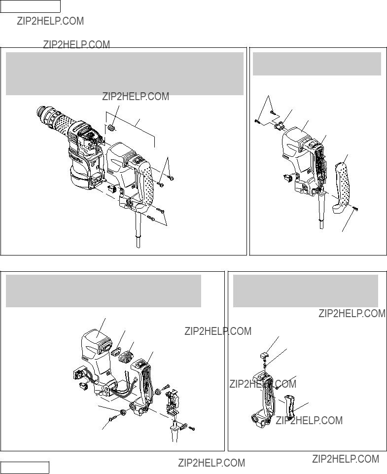
DISASSEMBLY
Handle section consists of the following main parts: Handle base, Handle, Handle cover
And it can be disassembled as illustrated in Figs. 17 - 20.
1.Separate Handle section from the machine first by removing the four screws illustrated below, then by disconnecting Connector housing of Controller from Motor housing; Compression spring 14 can be removed from Crank housing in this step.
Compression spring 14
Handle section
M5x20 Pan head screw (2 pcs)
Connector housing  of Controller
5x25 Tapping screw (2 pcs)
2.Remove Handle cover and Spring guide from Handle base.
4x18 Tapping screw (2 pcs)
Spring guide
Handle base
Handle
Handle cover
4x18 Tapping screw (1 pc)
Fig. 19
3.Separate Handle from Handle base.
Note: See Fig. 10 for disassembling the electrical parts in Handle section.
Handle base
Dust cover support
Dust cover
Handle
Shoulder sleeve 6 (2 pcs)
5x25 Tapping screw (2 pcs)
ASSEMBLY
Do the reverse of the disassembling steps.
Fig. 20
4.Remove Switch lever and Stop ring E-4 from Handle. Compression spring 8 and Lock-on button can now be removed.
Lock-on button
Compression spring 8
Stop ring E-4
Switch Lever
P 11/17
 Repair
[3] DISASSEMBLY/ASSEMBLY
[3] -7. Recommended Fastening Torque of Screws and Bolts
Tighten the bolt to the recommended torque described in Fig. 21.
Fig. 21
 Crank housing
  complete
[4] MAINTENANCE PROGRAM
When replacing carbon brush, it is recommended to do the following maintenance at the same time for longer service life of the machine.
1)Replace the parts described in Fig. 22 with new ones.
2)Wash out or wipe off old grease in Crank housing complete, and lubricate the parts in accordance with the instructions in [2] LUBRICATION. (Refer to Fig. 1.)
Fig. 22
Fig. D-1B
Low Voltage Areas where Radio Interference Suppression Is Required
Polyolefin tube (Protective tube)
Connector
P 13/17
 Wiring diagram
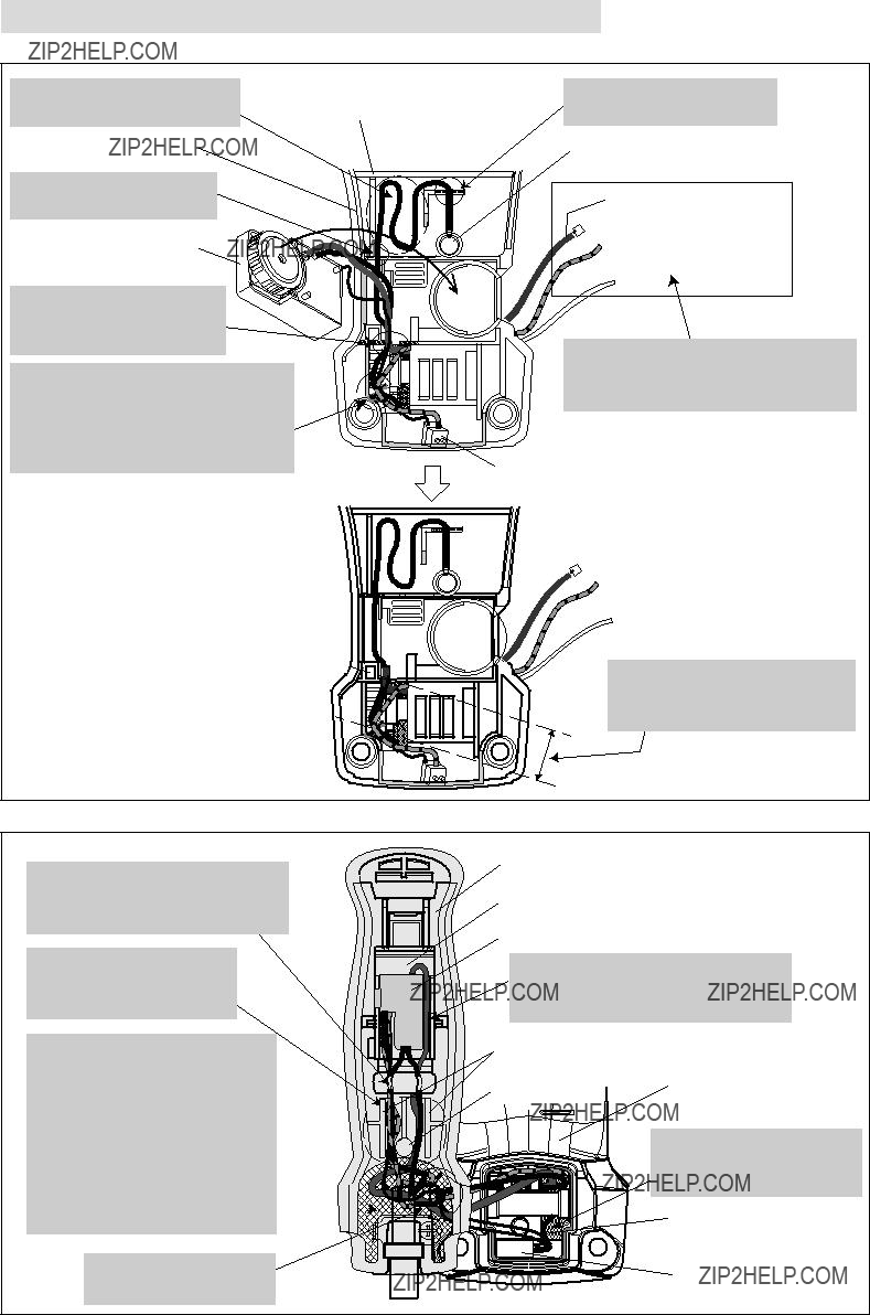
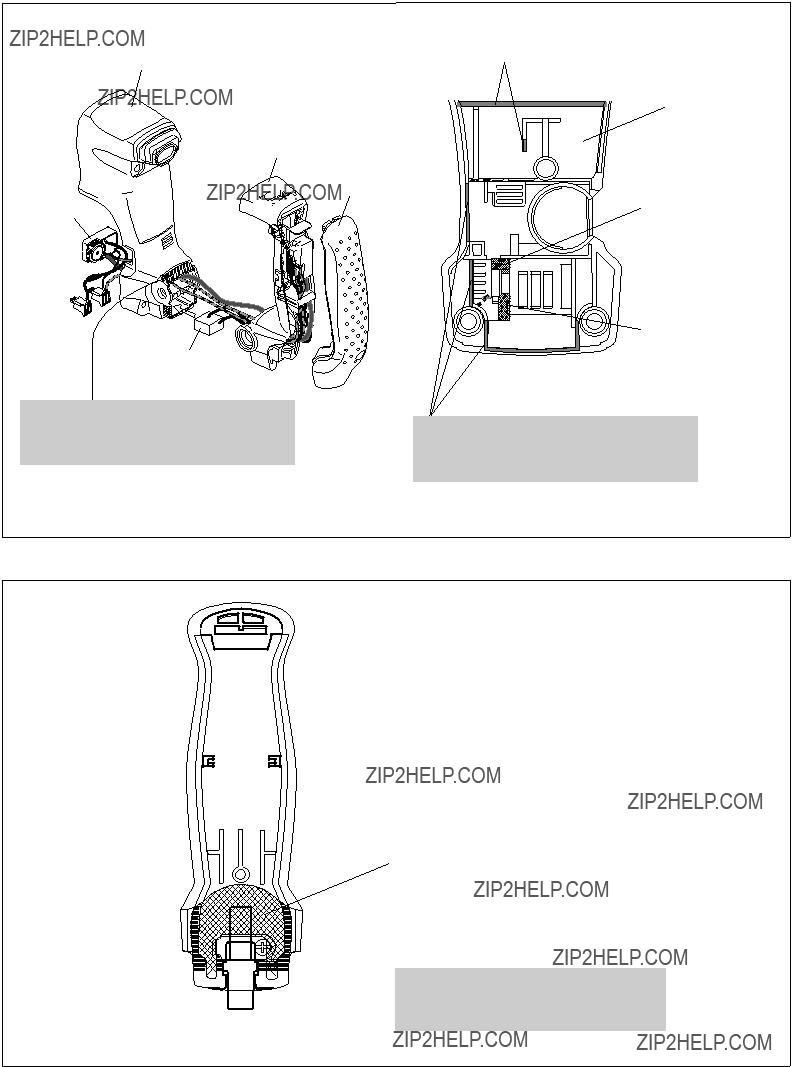
[1] Routing Wires Through Handle Base and Handle
Be careful not to pinch the Lead wires with the ribs. (Figs. D-2, D-3)
Fig. D-2
Handle base, viewed from Controller side
Through hole for passing Lead wires from Controller and Connector housing to the opposite side
Through hole for passing Grounding (Earth) wire from the opposite side
Do not put the Lead wires on this rib or they will be pinched between the rib and Handle.
Do not to put the Lead wires on these ribs or they will be pinched between the ribs and Motor housing.
P 14/17
 Wiring diagram
[2] Wiring in Handle Base and Handle
High Voltage Areas where Radio Interference Suppression Is Required
Fig. D-4A
Handle base, viewed from Controller side 

Controller
Route all of the Controller's
Lead wires through this slit.
Fix the following Lead wires of Controller with this Lead wire holder: *Lead wire (orange) to Choke coil *Lead wires (black, red) to Connector
housing A
Lead wires covered with Polyolefin tube (black)
red
 blue
blue
Pass these Lead wires from Controller and Connector housing A through
the hole illustrated to right in Fig. D-2.
Connector housing B
The Lead wires to Connector housings must be tight between Controller and Lead wire holder.
Fix all of the Lead wires to Switch with this Lead wire holder of Switch holder complete.
Handle, viewed from Handle cover side
Switch holder
Switch
Pass Controller???s Lead wires covered with Polyolefin tube (black) between Switch and Switch holder's wall.
P 15/17
 Wiring diagram
[2] Wiring in Handle Base and Handle
Low Voltage Areas where Radio Interference Suppression Is Required
Fig. D-4B
Controller
The Lead wires to Connector housing A must be tight between Controller and Lead wire holder.
Fig. D-5B
Fix all of the Lead wires to Switch with this Lead wire holder of Switch holder complete.
Handle, viewed from Handle cover side
Switch holder
Switch
Route all of the Lead wires to Switch through between the boss and the rib.
Pass the following Lead wires through this hole: *Noise suppressor's Lead
wires (black)  *Controller???s Lead wires covered
  with Polyolefin tube (black)
 *Lead wire (red) from
 Connector housing A

*Controller's Lead wire (white)
Put the slack portion of
Lead wires in this space.
Pass Controller???s Lead wires covered with Polyolefin tube (black) between Switch and Switch holder's wall.
Pass Grounding wire (clear) through the hole illustrated to right in Fig. D-2.
P 16/17
 Wiring diagram
[2] Wiring in Handle Base and Handle
Other Areas where Radio Interference Suppression Is Not Required
Fig. D-4C
Handle base, viewed from Controller side
Controller
Route all of the Controller's 

 Lead wires through this slit.

Fix the following Lead wires of Controller with this Lead wire holder: *Lead wires (black, red) to Connector
housing A
Lead wires covered with Polyolefin tube (black)
red
 blue
blue
Pass these Lead wires from Controller and Connector housing A through
the hole illustrated to right in Fig. D-2.
Connector housing A
The Lead wires to Connector housing A must be tight between Controller and Lead wire holder.
Fix all of the Lead wires to Switch with this Lead wire holder of Switch holder complete.
Route all of the Lead wires to Switch through between the boss and the rib.
Pass the following Lead wires through this hole:
*Controller???s Lead wires covered with Polyolefin tube (black)
*Lead wire (red) from Connector housing A
*Controller's Lead wire (blue)
Put the slack portion of
Lead wires in this space.
Handle, viewed from Handle cover side
Switch holder
Switch
Pass Controller???s Lead wires covered with Polyolefin tube (black) between Switch and Switch holder's wall.
P 17/17
 Wiring diagram
[3] Connecting Connector Housing with Brush Holder Unit
Connector housing is directional when connected with Brush holder complete in Motor housing. Be sure to connect as described in Fig. D-6.
Fig. D-6
The side where Lead wires are drawn out must be placed on Rear cover side as illustrated blow.
Rear cover
[DO NOTs]
1. The side where Lead wires are drawn out must not be placed on the opposite side to Rear cover.
2. Do not put Lead wires on Connector housing(s) or Lead wires will be pinched between Handle base and Motor housing.

 H
H


 Screw (4 pcs)


 Handle cover Controller


 viewed from Handle cover side


 Do not to put the Lead wires on this rib or they will be pinched between the rib and Handle cover.
 *Controller???s Lead wires covered
 with Polyolefin tube (black)
 *Lead wire (red) from
 Connector housing A