6.No opere la m??quina estando bajo los efectos del alcohol o de drogas.
7.El silenciador y el motor se calientan y producen una quemadura. No los toque.
8.Sea sumamente precavido cuando opere la m??quina sobre una superficie con grava o cuando la cruce. Mant??ngase alerta por si se presentan peligros ocultos o tr??fico.
9.Tenga cuidado cuando cambie de direcci??n o cuando opere la m??quina en pendientes.
10.Planifique el patr??n en el que va a ir arrojando nieve para evitar que la descarga de material se produzca hacia las ventanas, las paredes, los autos, etc. para evitar da??os materiales o lesiones producidas por los rebotes.
11.Nunca dirija la descarga hacia los ni??os, los observadores y a las mascotas ni deje que nadie se pare delante de la m??quina.
12.No sobrecargue la capacidad de la m??quina tratando de sacar la nieve muy r??pidamente.
13.Nunca opere esta m??quina si no tiene buena visibilidad o iluminaci??n. Siempre debe estar seguro de que est?? bien afirmado y sostenga bien las manijas. Camine, nunca corra.
14.Corte la corriente a la barrena / motor cuando transporte la m??quina o cuando la misma no est?? en uso.
15.Nunca opere la m??quina a alta velocidad de desplazamiento sobre superficies resbaladizas. Mire hacia abajo y hacia atr??s y tenga cuidado cuando la use en reversa.
16.Si la m??quina comenzara a vibrar de manera anormal, detenga el motor, desconecte la buj??a y p??ngala de manera que haga masa contra el motor. Inspeccione la m??quina minuciosamente para ver si est?? da??ada. Repare todos los da??os antes de encender y operar la m??quina.
17.Desengrane todas las palancas de embrague y detenga el motor antes de dejar la posici??n de operaci??n (detr??s de las manijas). Espere a que la barrena / motor se detenga por completo antes de destapar el canal de descarga, de realizar ajustes o inspecciones.
18.Nunca ponga las manos en las aberturas de descarga o de recolecci??n. Utilice siempre una herramienta de limpieza para destapar la abertura de descarga.
19.Use s??lo uniones y accesorios aprobados por el fabricante (por ejemplo, pesas para las ruedas, cadenas para los neum??ticos, cabinas, etc.).
20.Si se presentan situaciones que no est??n previstas en este manual sea cuidadoso y use el sentido com??n. Comun??quese con su distribuidor o llame al tel??fono 1-800-800-7310 por ayuda y para obtener el nombre del distribuidor m??s cercano.
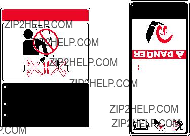
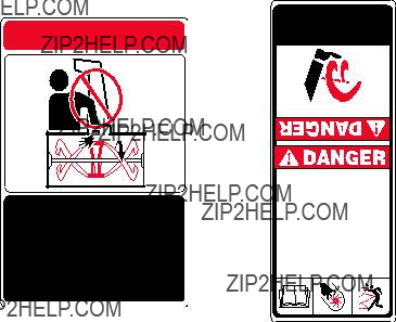
 DANGER
 NEVER PUT HAND IN CHUTE. CONTACT WITH
ROTATING PARTS CAN AMPUTATE FINGERS
AND HANDS.
 DO NOT UNCLOG DISCHARGE CHUTE WHILE
ENGINE IS RUNNING.
 SHUT OFF ENGINE AND REMAIN BEHIND
HANDLES UNTIL ALL MOVING PARTS HAVE
STOPPED BEFORE UNCLOGGING.
Mantenimiento y almacenamiento
1.Nunca manipule los dispositivos de seguridad de manera imprudente. Verifique regularmente si funciona de manera correcta.
2.Desengrane todas las palancas de embrague y detenga el motor. Espere a que la barrena / motor se detenga por completo. Desconecte el cable de la buj??a y p??ngalo de manera que haga masa contra el motor para evitar que se encienda de manera accidental antes de limpiar, reparar o revisar la m??quina.
3.Controle frecuentemente que todos los pernos y tornillos est??n bien ajustados para comprobar que la m??quina se encuentra en condiciones seguras de operaci??n. Adem??s realice una inspecci??n visual de la m??quina para controlar si la misma est?? da??ada.
4.No cambie la configuraci??n del regulador del motor ni acelere demasiado el mismo. El regulador controla la velocidad m??xima segura de operaci??n del motor.
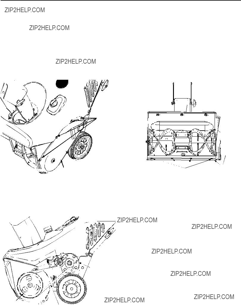
5.Las placas de raspado y los zapatos anti deslizantes de que se usan con la m??quina quitanieves se desgastan y se da??an. Para proteger su seguridad, verifique frecuentemente todos los componentes y reempl??celos s??lo con partes de los fabricantes de equipos originales (O.E.M.). ???La utilizaci??n de partes que no cumplan con las especificaciones de equipos originales podr??a tener como resultado un rendimiento incorrecto y adem??s la seguridad podr??a estar comprometida???
6.Revise los controles del embrague peri??dicamente para verificar que engranen y desengranen adecuadamente y aj??stelos si es necesario. Consulte la secci??n de ajustes en este manual del operador para obtener instrucciones.
7.Mantenga o reemplace las etiquetas de seguridad e instrucciones seg??n sea necesario.
8.Respete las leyes y reglamentaciones referentes a la
disposici??n correcta de gas, aceite, etc. para proteger el medio ambiente.
9.Antes de almacenar la m??quina enci??ndala unos minutos para sacar la nieve que haya quedado en la misma y para evitar as?? que se congele la barrena / motor.
10.Nunca almacene la m??quina o el recipiente de combustible en un espacio cerrado donde haya fuego, chispas o luz piloto como por ejemplo, calentadores de agua, hornos, secadores de ropa, etc.
11.Siempre consulte el manual del operador para obtener instrucciones correctas acerca del almacenamiento fuera de temporada.
Su responsabilidad:
???S??lo permita que usen esta m??quina el??ctrica las personas que lean, comprendan y respeten las advertencias y las instrucciones que aparecen en este manual y en la m??quina.
ANDCLOTHING.AWAY KEEPHANDS,FEET ROTATINGAUGER- AVOIDINJURYFROM
1.KEEP AWAY FROM ROTATING AUGER
CONTACT WITH AUGER CAN AMPUTATE
HANDS AND FEET.
2.DISENGAGE CLUTCH LEVERS, STOP ENGINE,
AND REMAIN BEHIND HANDLES UNTIL ALL
MOVING PARTS HAVE STOPPED BEFORE
UNCLOGGING OR SERVICING MACHINE.
3.TO AVOID THROWN OBJECTS INJURIES,
NEVER DIRECT DISCHARGE AT BYSTANDERS.
USE EXTRA CAUTION WHEN OPERATING ON
GRAVEL SURFACES.
4.READ OPERATOR'S MANUAL.


 DANGER
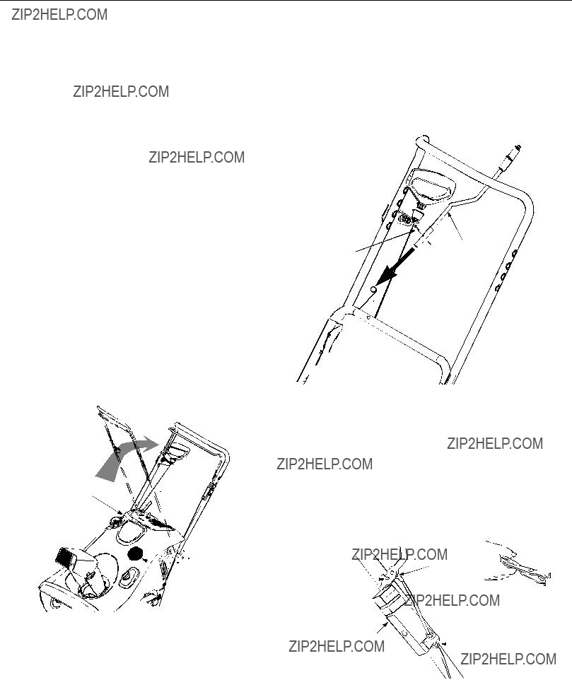

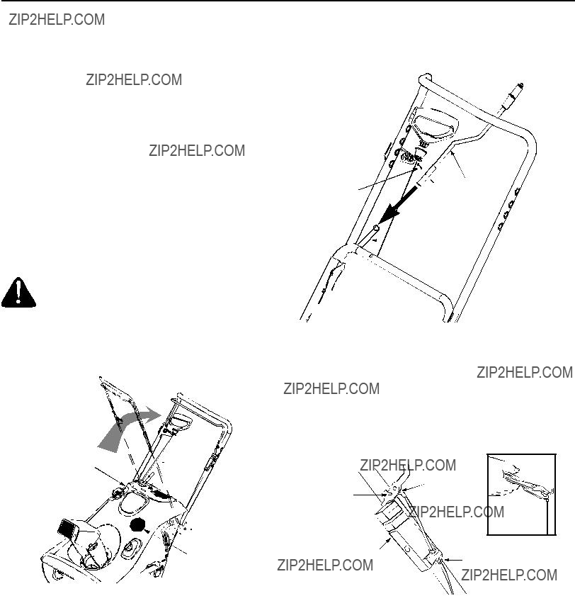
 Lower Chute


 Hand Knob
 Spark Plug
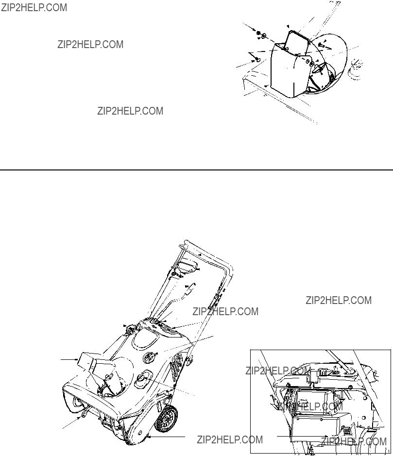

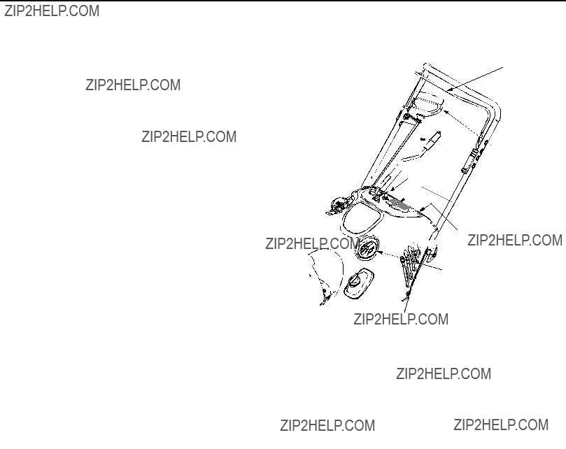


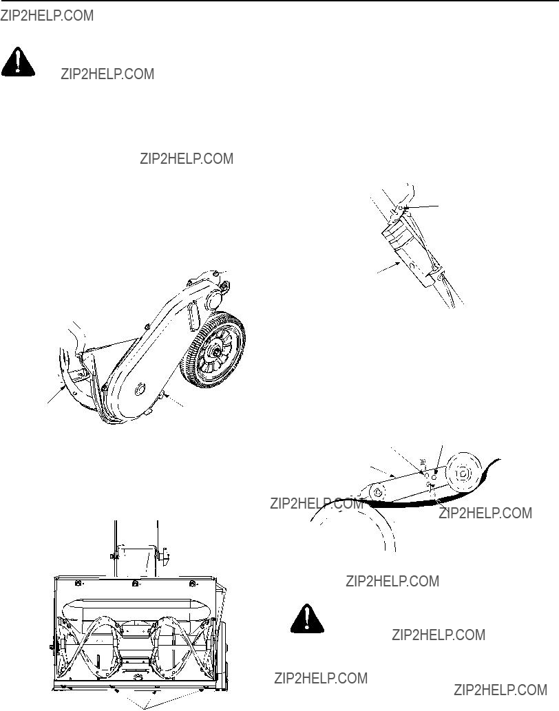
 Lever
Lever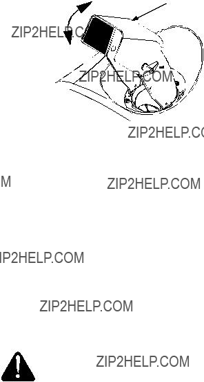


 Hole
Hole Cable
Cable

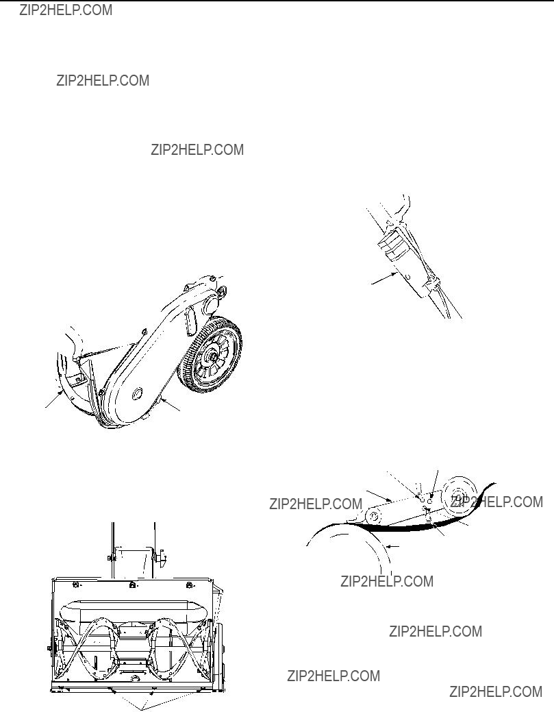
 Hex
Hex


 Hex Screw


 Belt Cover


 15
15


 Perilla manua
 Buj??a de encendid
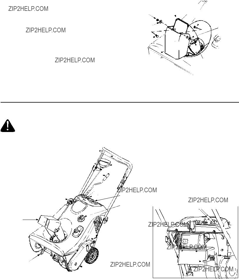


 Llave
Llave

 Obturaci??Arrancador*


 Palanca
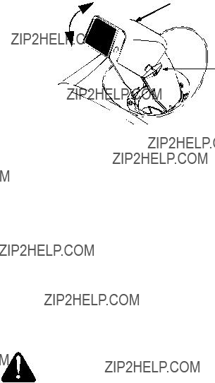
 Cable
Cable
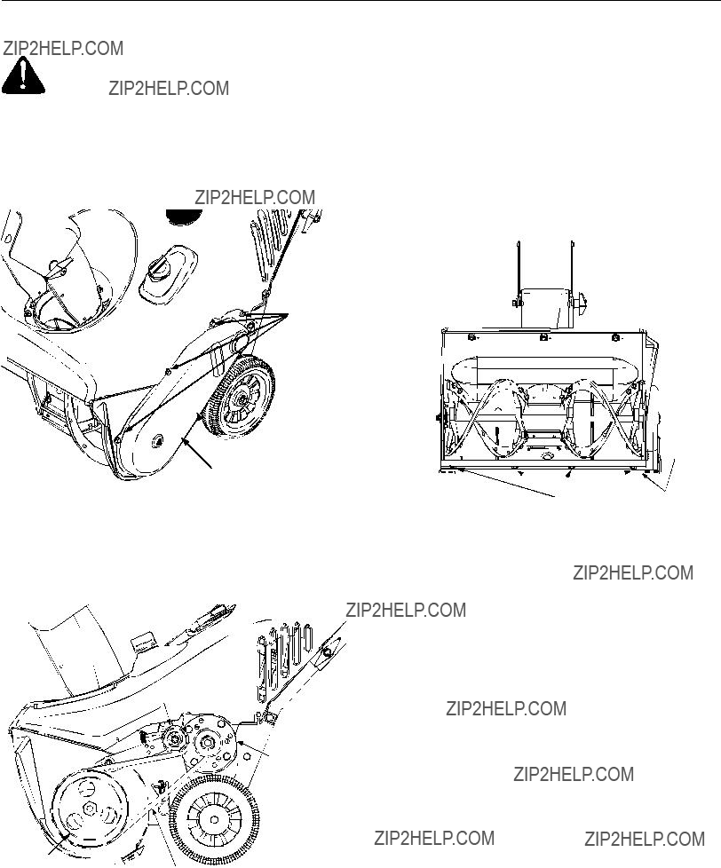


 Tornillo