Pub.
www.lowrance.com
Installation and Operation
Instructions
Pub.
www.lowrance.com
Installation and Operation
Instructions

Copyright ?? 2006 Lowrance Electronics, Inc.
All rights reserved.
No part of this manual may be copied, reproduced, republished, trans- mitted or distributed for any purpose, without prior written consent of Lowrance. Any unauthorized commercial distribution of this manual is strictly prohibited.
Lowrance?? is a registered trademark of Lowrance Electronics, Inc. MapCreate???, FreedomMaps??? and NauticPath??? are trademarks of LEI. Fishing Hot Spots??? is a registered trademark of Fishing Hot Spots Inc. LakeMaster??? and Pro Maps are trademarks or registered trade- marks of WayPoint Technologies, Inc. Navionics??? is a registered trademark of Navionics, Inc. DURACELL??? is a registered trademark of Duracell, Inc. RAYOVAC??? is a registered trademark of Rayovac Corpo- ration. Energizer??? and e2??? are registered trademarks of Energizer Hold- ings, Inc.
 Points of Interest Data in this unit are by infoUSA,
  copyright ???
Lowrance Electronics may find it necessary to change or end our poli- cies, regulations and special offers at any time. We reserve the right to do so without notice. All features and specifications subject to change without notice. All screens in this manual are simulated. On the cover:
For free owner's manuals and the most current information on this product, its operation and accessories,
visit our web site:
www.lowrance.com
Lowrance Electronics Inc.
12000 E. Skelly Dr.
Tulsa, OK USA
Printed in USA.
vi
NOTICE!
The storage and operation temperature range for your unit is from
WARNING!
A CAREFUL NAVIGATOR NEVER RELIES ON ONLY ONE METHOD
TO OBTAIN POSITION INFORMATION.
CAUTION
When showing navigation data to a position (waypoint), a GPS unit will show the shortest, most direct path to the waypoint. It provides navigation data to the waypoint regardless of obstructions. Therefore, the prudent navigator will not only take advantage of all available navigation tools when traveling to a way- point, but will also visually check to make sure a clear, safe path to the waypoint is always available.
WARNING!
When a GPS unit is used in a vehicle, the vehicle operator is solely re- sponsible for operating the vehicle in a safe manner. Vehicle operators must maintain full surveillance of all pertinent driving, boating or flying conditions at all times. An accident or collision resulting in damage to property, personal injury or death could occur if the operator of a GPS- equipped vehicle fails to pay full attention to travel conditions and vehi- cle operation while the vehicle is in motion.
vii
Notes
viii
Section 1: Read Me First!
How this manual can get you out on the road, fast!
Welcome to the exciting world of digital sonar and GPS! We know you're anxious to begin navigating and finding fish, but we have a favor to ask. Before you grab the unit and begin installing it, please give us a moment or two to explain how our manual can help you get the best performance from your compact,
First, we want to thank you for buying a Lowrance sonar/GPS unit. Whether you're a first time user or a professional fisherman, you'll dis- cover that your unit is easy to use, yet capable of handling demanding navigation and sonar tasks. When you team your unit with our custom mapping software MapCreate???, you have an incredible combination. You won't find another combination GPS and sonar unit with this much power and this many features for this price!
Our goal for this book is to get you on the water fast, with a minimum of fuss. Like you, we'd rather spend more time boating or fishing and less time reading the manual!
So, we designed our book so that you don't have to read the whole thing from front to back for the information you want. At the start (or end) of each segment, we'll tell you what content is coming up next. If it's a concept you're already familiar with, we'll show you how and where to skip ahead for the next important topic. We've also made it easy to look up any tips you may need from time to time. Here's how:
The manual is organized into 10 sections. This first section is an intro- duction to the
Section 2 will help you install your unit, the transducer and the GPS antenna module. We'll show you how to get the MultiMedia Card (MMC) correctly installed inside the unit. We'll also tell you about some of the available accessories.
Section 3 covers Basic Sonar Operation. It will show you how easy it is to run your sonar, right out of the box. This section features a
1
After you've gained some experience with your sonar, you'll want to check out Section 4, which discusses more advanced Sonar Options and Other Features.
When you come to a sonar menu command on your unit???s screen, you can look it up in the manual by skimming over the table of contents, just flip- ping through Section 3 or scanning through the sonar options in Section 4.
If you're having difficulty with your sonar, you can find an answer to the most common problems in Section 5, Sonar Troubleshooting.
The manual switches from sonar to navigation in Section 6, which in- troduces you to Basic GPS Operations. This section features a one- page GPS Quick Reference on page 121.
Section 6 contains short,
After you've learned the basics (or if you already have some GPS ex- perience), you may want to try out some of the unit???s many advanced navigation features. That brings us to Section 7, Advanced GPS Opera- tions. This section contains the rest of your unit???s GPS command func- tions, organized in alphabetical order.
When you come to a GPS menu command on the screen, you can look it up in the manual by skimming over the table of contents, just flipping through Section 6 or scanning through the command portion of Section 7.
Your unit is ready to use right out of the box, but you can fine tune and customize it's operation with dozens of options. Since sonar is the unit's key feature, we put the main sonar options in Section 4. Some options, such as screen brightness settings, affect both sonar and GPS opera- tions. We describe how to use those common options along with GPS options in Section 8, System Setup and GPS Setup Options. Section 8 is organized in alphabetical order.
In Section 9, we go into more detail on one of the unit???s most remarkable GPS capabilities ??? Searching. We'll introduce a search example in the Basic GPS Operation section, but there are so many map items you can search for, we had to give this function it's own section in the manual! For example, did you know your unit can look up business phone numbers, functioning as a virtual Yellow Pages? We???ll show you how in Section 9.
Finally, in Section 10, we offer Supplemental Material, including a list of the GPS datums used, warranties and customer service information.
2
Specifications:
NOTE:
The above memory capacities refer only the unit???s
How Lowrance Sonar Works
Sonar has been around since the 1940s, so if you already know how it works, skip down to read about the relatively new technology of GPS. But, if you've never owned a sonar fish finder, this segment will tell you the under water basics.
Sonar is an abbreviation for SOund NAvigation and Ranging, a technol- ogy developed during World War II for tracking enemy submarines. (Lowrance developed the world's first transistorized sportfishing sonar in 1957.) A sonar consists of a transmitter, transducer, receiver and dis- play. In simple terms, here's how it finds the bottom, or the fish:
The transmitter emits an electrical impulse, which the transducer con- verts into a sound wave and sends into the water. (The sound frequency can't be heard by humans or fish.) The sound wave strikes an object (fish, structure, bottom) and bounces back to the transducer, which converts the sound back into an electrical signal.
The receiver amplifies this return signal, or echo, and sends it to the display, where an image of the object appears on the scrolling sonar chart. The sonar's microprocessor calculates the time lapse between the transmitted signal and echo return to determine the distance to the object. The whole process repeats itself several times each second.
Your unit can record a log of the sonar signals that scroll across the screen and save them to the MMC memory card. (These recordings are
5
also called sonar charts or sonar graphs.) You can replay this sonar log in the unit using the Sonar Simulator function, or play it back on a per- sonal computer using our free Sonar Viewer. The viewer is available for download from the Lowrance web site, www.lowrance.com.
You can save several different sonar log files, erase 'em and record new ones, over and over again. The size of your sonar recordings is only lim- ited by the free space available on your MMC.
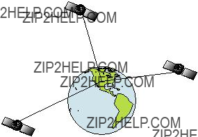
How Lowrance GPS Works
You'll navigate faster and easier if you understand how your unit scans the sky to tell you where you are on the earth ??? and, where you're go- ing. First, think of your unit as a small but powerful computer. (But don't worry ??? we made the unit easy to use, so you don't need to be a computer expert to find your way!) It includes a keypad and a screen with menus so you can tell it what to do. The screen also lets the unit show your location on a moving map, as well as point the way to your destination.
This
Your unit listens to signals from as many satellites as it can "see" above the horizon, eliminates the weakest signals, then computes its location in relation to those satellites. Once the unit figures its latitude and longitude, it plots that position on the moving map shown on the screen. The whole process takes place several times a second!
The performance doesn't stop there. Stored in the permanent memory of each unit is a basic background map of the entire world. We lock it in here at the factory ??? you can't change or erase this map.
The background map is suitable for many navigation chores, but for maximum accuracy and much more detail, you need our optional map- making software, MapCreate???. Some unit features ??? such as search- ing for businesses and addresses ??? won't work without a custom Map- Create map.
There is so much detail in our background map (and even more in MapCreate) that we'll describe their contents and differences in Section 6, Basic GPS Operations, on page 105.
Another portion of the unit???s onboard memory is devoted to recording GPS navigation information, which includes waypoints, event marker
6
icons, trails and routes. This lets you look back the way you came. Think of this data storage like the hard drive memory in a computer or a tape in a cassette tape recorder. You can save several different GPS data files, erase 'em and record new ones, over and over again. These GPS Data Files (file format *.usr) can be shared between, not only the
Your unit has one more thing in common with a personal computer. Just as computers have a floppy disk drive for storing and exchanging files, the unit has a slot for an MMC (MultiMedia Card) or SDC (Secure Digital card) flash memory card. These
First, you can backup your onboard GPS Data Files by copying them to the MMC. Since the MMC is removable (like a floppy disk or a cassette tape), you can store these GPS Data Files on a personal computer equipped with an MMC card reader. (Or store them on a pocketful of MMCs, if you don't have a computer.) Our MapCreate mapping software can save, edit or create its own GPS Data Files, which can be copied to the MMC and then loaded from the MMC into unit???s memory. (NOTE: No matter where they come from, GPS Data Files must be loaded from the MMC into memory before your unit can use them.)
The other key GPS use for MMCs is storage of special
Your unit automatically reads Custom Map Files directly from the MMC or SDC. To use a custom map, all you need to do is slide an MMC containing a map into the unit.
Introduction to GPS and WAAS
Well, now you know the basics of how your unit does its work. You might be ready to jump ahead to Section 2, Installation & Accessories,
7
on page 13, so you can mount your unit and plug in the power. Or you might want to see how our text formatting makes the manual tutorials easy to skim. If that's the case, move on to "How to Use This Manual" on page 10. But, if you want to understand the current state of satellite navigation, look over this segment describing how GPS and its new companion WAAS work together to get you where you're going.
The Global Positioning System (GPS) was launched July 17, 1995 by the United States Department of Defense. It was designed as a 24-
GPS proved so useful for civilian navigation that the federal govern- ment discontinued SA on May 2, 2000, after the military developed other methods to deny GPS service to enemy forces. Reliable accuracy for civilian users jumped from 100 meters (330 feet) under SA to the present level of 10 to 20 meters (about 30 to 60 feet.)
A minimum of three satellites are required to determine a 2D fix.
The system requires signal reception from three satellites in order to determine a position. This is called a 2D fix. It takes four satellites to determine both position and elevation (your height above sea level ??? also called altitude.) This is called a 3D fix.
8
Remember, the unit must have a clear view of the satellites in order to receive their signals. Unlike radio or television signals, GPS works at very high frequencies. These signals can be easily blocked by trees, buildings, an automobile roof, even your body.
Like most GPS receivers, the unit doesn???t have a compass or any other navigation aid built inside. It relies solely on the signals from the satel- lites to calculate a position. Speed, direction of travel, and distance are all calculated from position information. Therefore, in order it to de- termine direction of travel, you must be moving and the faster, the bet- ter. This is not to say that it won???t work at walking or trolling speeds ??? it will. There will simply be more "wandering" of the data shown on the display.
GPS alone is plenty accurate for route navigation, but the U.S. Federal Aviation Administration has special aircraft navigation needs that go beyond basic GPS. So, the FAA has developed a program to boost GPS performance with its Wide Area Augmentation System, or WAAS. The FAA commissioned the system on July 11, 2003.
WAAS is designed to increase GPS accuracy to within 7.6 meters vertically and horizontally, but it consistently delivers accuracies within
However, there are some fringe areas of the U.S., including parts of Alaska that do not yet receive robust WAAS coverage. Continued WAAS development is planned to extend WAAS coverage in the years to come.
WAAS boosts the accuracy of land GPS navigation, but the system is designed for aircraft. The satellites are in a fixed orbit around the Equator, so they appear very low in the sky to someone on the ground in North America. Aircraft and vessels on open water can get consis- tently good WAAS reception, but terrain, foliage or even large
You'll find that using your GPS receiver is both easy and amazingly accurate. It???s easily the most accurate method of electronic navigation available to the general public today. Remember, however, that this receiver is only a tool. Always have another method of navigation avail- able, such as a map or chart and a compass.
Also remember that this unit will always show navigation information in the shortest line from your present position to a waypoint, regardless
9
of terrain! It only calculates position, it can???t know what???s between you and your destination, for example. It???s up to you to safely navigate around obstacles, no matter how you???re using this product.
How to use this manual: typographical conventions
Many instructions are listed as numbered steps. The keypad and arrow "keystrokes" appear as boldface type. So, if you're in a real hurry (or just need a reminder), you can skim the instructions and pick out what menu command to use by finding the boldface command text. The fol- lowing paragraphs explain how to interpret the text formatting for those commands and other instructions:
Arrow Keys
The arrow keys control the movement of dotted
10
Keyboard
The other keys perform a variety of functions. When the text refers to a key to press, the key is shown in bold, sans serif type. For example, the "Enter/Icons" key is shown as ENT and the "Menu" key is shown as MENU.
Menu Commands
A menu command or a menu option will appear in small capital letters, in a bold sans serif type like this: ROUTE PLANNING. These indicate that you are to select this command or option from a menu or take an action of some kind with the menu item. Text that you may need to enter or file names you need to select are show in italic type, such as trail name.
Instructions = Menu Sequences
Most functions you perform with your unit are described as a sequence of key strokes and selecting menu commands. We've written them in a condensed manner for quick and easy reading.
For example, instructions for navigating a trail would look like this:
1.From the Map Page, press MENU|MENU|??? to MY TRAILS|ENT.
2.Press ??? to Trail 1|ENT|???|??? to NAVIGATE|ENT.
3.You are asked to wait while it converts the trail into a route.
4.The wait message disappears and the unit begins showing navigation information along the trail.
Translated into complete English, step 1 above would mean: "Start on the Map Page. Press the Menu key twice. Next, repeatedly press (or press and hold) the down arrow key to scroll down the menu and select (highlight) the My Trails menu command. Finally, press the Enter key."
Step 2 would mean: "Press the down arrow key repeatedly to scroll to the trail named Trail 1, and press Enter. Next, press the right arrow key and then the down arrow key to highlight the Navigate command, then press Enter."
11
Notes
12
Section 2: Installation
Preparations
You can install the sonar and GPS systems in some other order if you prefer, but we recommend this installation sequence:
Caution:
You should read over this entire installation section before drill- ing any holes in your vehicle or vessel!
1.Determine the approximate location for the sonar/GPS unit, so you can plan how and where to route the cables for the antenna, transducer and power. This will help you make sure you have enough cable length for the desired configuration.
2.Determine the approximate location for the transducer and its cable route.
3.Determine the approximate location for the GPS antenna module and its cable route.
4.Determine the location of your battery or other power connection, along with the power cable route.
5.Install the transducer and route the transducer cable to the so- nar/GPS unit.
6.Install the GPS antenna and route the antenna cable to the so- nar/GPS unit.
7.Install the power cable and route it to the sonar/GPS unit.
8.Mount the sonar/GPS unit to the bracket.
Transducer Installation
These instructions will help you install your Skimmer??? transducer on a transom, on a trolling motor or inside a hull. These instructions cover both single- and
The smaller
These are all
13
Read these instructions carefully before attempting the installation. Determine which of the mounting positions is right for your boat. Re- member, the transducer installation is the most critical part of a sonar installation.
NOTE:
The following installation types also call for these recommended tools and required supplies that you must provide (supplies listed here are not included):
Tools include: two adjustable wrenches, drill, #29 (0.136") drill bit, flat-
head screwdriver. Supplies: high quality, marine grade above- or below- waterline sealant/adhesive compound.
Tools: two adjustable wrenches, drill, #20 (0.161") drill bit,
screwdriver. Supplies: four, 1" long, #12 stainless steel slotted wood screws, high quality, marine grade above- or
Tools: two adjustable wrenches,
Tools: these will vary depending on your hull's composition. Consult your boat dealer or manufacturer. Other tools are a wooden craft stick or similar tool for stirring and applying epoxy, and a paper plate or piece of cardboard to mix the epoxy on. Supplies: rubbing alcohol, 100 grit sandpaper, specially formulated epoxy adhesive available from LEI (see ordering information on the inside back cover). A sandwich hull also requires polyester resin.
Selecting a Transducer Location
1.The location must be in the water at all times, at all operating speeds.
2.The transducer must be placed in a location that has a smooth flow of water at all times. If the transducer is not placed in a smooth flow of water, interference caused by bubbles and turbulence will show on the sonar's display in the form of random lines or dots whenever the boat is moving.
NOTE:
Some aluminum boats with strakes or ribs on the outside of the hull create large amounts of turbulence at high speed. These boats typically have large outboard motors capable of propelling the boat
14

at speeds faster than 35 mph. Typically, a good transom location on aluminum boats is between the ribs closest to the engine.
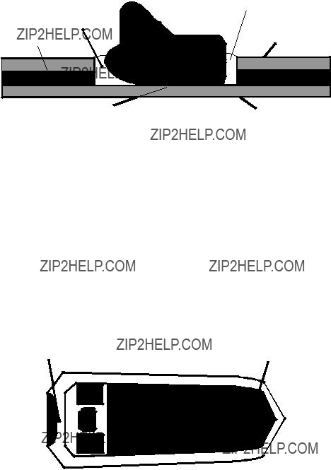
3.The transducer should be installed with its face pointing straight down, if possible. For
Pad
Deadrise less than 10??
 Strakes
Left, vee pad hull; right, vee hull. A pod style transducer is shown here, but the principle is the same for Skimmers inside a hull.
4.If the transducer is mounted on the transom, make sure it doesn't interfere with the trailer or hauling of the boat. Also, don't mount it closer than approximately one foot from the engine's lower unit. This will prevent cavitation (bubble) interference with propeller opera- tion.
5.If possible, route the transducer cable away from other wiring on the boat. Electrical noise from engine wiring, bilge pumps and aerators can be displayed on the sonar's screen. Use caution when routing the transducer cable around these wires.
CAUTION: Clamp the trans- ducer cable to transom near the transducer. This will help prevent the transducer from entering the boat if it is knocked off at high speed.
Good location
Good and poor transducer locations.
15
How low should you go?
For most situations, you should install your Skimmer transducer so that its centerline is level with the bottom of the boat hull.
This will usually give you the best combination of smooth water flow and protection from bangs and bumps.
Transom
Transducer centerline
Hull bottom
Align transducer centerline with hull bottom.
However, there are times when you may need to adjust the transducer slightly higher or lower. (The slots in the mounting brackets allow you to loosen the screws and slide the transducer up or down.) If you fre- quently lose bottom signal lock while running at high speed, the trans- ducer may be coming out of the water as you cross waves or wakes. Move the transducer a little lower to help prevent this.
If you cruise or fish around lots of structure and cover, your transducer may be frequently kicking up from object strikes. If you wish, you may move the transducer a little higher for more protection.
There are two extremes you should avoid. Never let the edge of the mounting bracket extend below the bottom of the hull. Never let the bottom ??? the face ??? of the transducer rise above the bottom of the hull.
In a
Typically,
16

However, the
Second, the transducer angle cannot be adjusted for the best fish arches on your sonar display. (This is not an issue for
Third, a transducer CAN NOT shoot through wood and metal hulls. Those hulls require either a transom mount or a
Fourth, if your Skimmer transducer has a built in temp sensor, it will only show the temperature of the bilge, not the water surface temp.
Follow the testing procedures listed in the
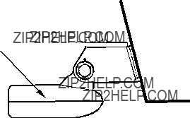
Transom Transducer Assembly And Mounting
The best way to install these transducers is to loosely assemble all of the parts first, place the transducer's bracket against the transom and see if you can move the transducer so that it's parallel with the ground.
The following instructions sometimes vary depending on the mounting bracket that came with your transducer.
1.Assembling the bracket.
A.
14?? transom. Most outboard and
Dot
Align plastic ratchets in bracket.
17

B.
Place the ratchets into the bracket with the letter "A" aligned with the alignment mark molded into the bracket. Place the ratchets onto the transducer with the letter "A" aligned with the 12 o'clock position on the transducer stem. These positions set the transducer's coarse angle adjustment for a 14?? transom. Most outboard and
Alignment letters
Alignment
positions
Transducer
Transducer bracket
Insert and align ratchets.
TransducerTransducer
bracket
Add ratchets to bracket and transducer.
2.Aligning the transducer on the transom.
A.
18

hold it against the transom. Looking at the transducer from the side, check to see if it will adjust so that its face is parallel to the ground. If it does, then the "A" position is correct for your hull.
If the transducer's face isn't parallel with the ground, remove the transducer and ratchets from the bracket.
Place the ratchets into the holes in the bracket with the letter "B" aligned with the dot stamped in the bracket.
Reassemble the transducer and bracket and place them against the transom. Again, check to see if you can move the transducer so it's parallel with the ground. If you can, then go to step 3A. If it doesn't, repeat step 2A, but use a different alignment letter until you can place the transducer on the transom correctly.
Ratchets
Insert bolt and check transducer position on transom.
B.
If the transducer's face isn't parallel with the ground, remove and disassemble the transducer and ratchets. Place the ratchets into the bracket holes with the letter "B" aligned with the bracket alignment mark. Place them on the transducer aligned with the 12 o'clock posi- tion on the transducer stem.
Reassemble the transducer and bracket and place them against the transom. Again, check to see if you can move the transducer so it's parallel with the ground. If you can, then go to step 3B. If it doesn't, repeat step 2B, but use a different alignment letter until you can place the transducer on the transom correctly.
19
Assemble transducer and bracket.
3.Assembling the transducer.
A.
ure. Don't tighten the lock nut at this time.
Metal
Nut washer
Assemble transducer and bracket.
B.
4.Drilling mounting holes.
Hold the transducer and bracket assembly against the transom. The transducer should be roughly parallel to the ground. The trans- ducer's centerline should be in line with the bottom of the hull. Don't let the bracket extend below the hull!
Mark the center of each slot for the mounting screw pilot holes. You will drill one hole in the center of each slot.
Drill the holes. For the
20
Transom
Transom
Position transducer mount on transom and mark mounting holes. Side view shown, left, and seen from above at right.
5.Attaching transducer to transom.
A.
For
Both bracket types: Attach the transducer to the transom. Slide the transducer up or down until it's aligned properly with the bottom of the hull as shown in the preceding and following figures. Tighten the bracket's mounting screws, sealing them with the sealant.
Adjust the transducer so that it's parallel to the ground and tighten the nut until it touches the outer washer, then add 1/4 turn. Don't over tighten the lock nut! If you do, the transducer won't
21

Bottom of hull
Align transducer centerline with hull bottom and attach transducer to transom. Rear view of
6.Route the transducer cable through or over the transom to the sonar unit. Make sure to leave some slack in the cable at the transducer. If possible, route the transducer cable away from other wiring on the boat. Electrical noise from the engine's wiring, bilge pumps, VHF radio wires and cables, and aerators can be picked up by the sonar. Use cau- tion when routing the transducer cable around these wires.
WARNING:
Clamp the transducer cable to the transom close to the transducer. This can prevent the transducer from enter- ing the boat if it is knocked off at high speed.
If you need to drill a hole in the transom to pass the connector through, the required hole size be 1".
Caution:
If you drill a hole in the transom for the cable, make sure it is located above the waterline. After installation, be sure to seal the hole with the same marine grade above- or
7.Make a test run to determine the results. If the bottom is lost at high speed, or if noise appears on the display, try sliding the trans- ducer bracket down. This puts the transducer deeper into the water, hopefully below the turbulence causing the noise. Don't allow the transducer bracket to go below the bottom of the hull!
22

Trolling Motor Bracket Installation
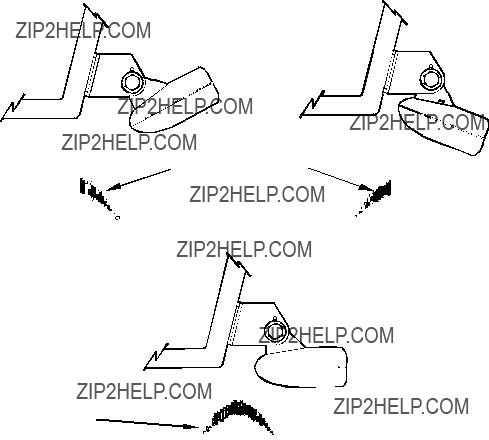
1.Attach the optional
 Internal tooth washer
Flat washer
Attach motor mounting bracket to transducer.
2.Slide the adjustable strap supplied with the
3.Route the transducer cable alongside the trolling motor shaft. Use plastic ties (not included) to attach the transducer cable to the troll- ing motor shaft. Make sure there is enough slack in the cable for the motor to turn freely. Route the cable to the sonar unit and the trans- ducer is ready for use.
Transducer mounted on trolling motor, side view.
Transducer Orientation and Fish Arches
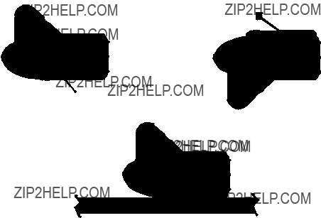
If you do not get good fish arches on your display, it could be because the transducer is not parallel with the ground when the boat is at rest in the water or at slow trolling speeds.
23
Full fish arch
Proper transducer angle
Transducer angles and their effects on fish arches.
If the arch slopes up ??? but not back down ??? then the front of the trans- ducer is too high and needs to be lowered. If only the back half of the arch is printed, then the nose of the transducer is angled too far down and needs to be raised.
NOTE:
Periodically wash the transducer's face with soap and water to re- move any oil film. Oil and dirt on the face will reduce the sensitiv- ity or may even prevent operation.
Hulls with Flotation Materials
The transducer installation inside a fiberglass hull must be in an area that does not have air bubbles in the resin or separated fiberglass lay- ers. The sonar signal must pass through solid fiberglass. A successful transducer installation can be made on hulls with flotation materials (such as plywood, balsa wood or foam) between layers of fiberglass if the material is removed from the chosen area. See the following figure.
24
WARNING:
Do not remove any material from your inner hull unless you know the hull's composition. Careless grinding or cutting on your hull can result in damage that could sink your boat. Contact your boat dealer or manufac- turer to confirm your hull specifications.
Fill with
Fill with resin
Epoxy the transducer to a solid portion of the hull.
For example, some (but not all) manufacturers use a layer of fiberglass, then a core of balsa wood, finishing with an outer layer of fiberglass. Removing the inner layer of fiberglass and the balsa wood core exposes the outer layer of fiberglass. The transducer can then be epoxied di- rectly to the outer layer of fiberglass. After the epoxy cures for 24 hours, fill the remaining space with polyester resin. When the job is finished, the hull is watertight and structurally sound. Remember, the sonar signal must pass through solid fiberglass. Any air bubbles in the fiberglass or the epoxy will reduce or eliminate the sonar signals.
Testing Determines Best Location
Ideally, the
25
To choose the proper location for
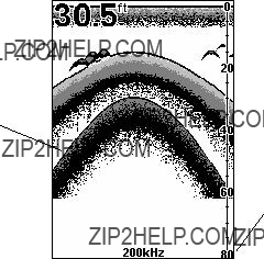
1.Anchor the boat in about 30 feet of water. Add a little water to the sump of the boat. Plug the transducer into the sonar unit, turn it on, then hold the transducer over the side of the boat in the water. Adjust the sensitivity and range controls until a second bottom echo is seen on the display. (You'll need to turn off Auto Sensitivity, Auto Depth Range and ASP???. Try a range setting that is two to three times the water depth. The harder (more rocky) the bottom, the easier it will be to get a second bottom signal.) Don't touch the controls once they've been set.
 True bottom
Second bottom
Manual range setting
Example of a second bottom signal. Unit is in 30 feet of water, with range set at 80 feet and sensitivity set at 87 percent.
2.Next, take the transducer out of the water and place it in the water in the sump of the boat, face down. (The transducer face is shown in the figure on the following page.) Notice how the signal strength decreases. The second bottom signal will probably disappear and the bottom sig- nal intensity will likely decrease.
3.Now move the transducer around to find the best location with the strongest possible bottom signal. If you find a spot with an acceptable bottom signal, mark the location and move on to step 4.
If you can't get an acceptable bottom signal, try turning up the sensitiv- ity by three or five keystrokes and then move the transducer around once more. If you find a spot that works, mark it and move on to step 4.
If you have to turn up sensitivity by more than five keystrokes to get a good signal, the transducer should be mounted on the outside of the hull. This is especially true if you have to turn sensitivity all the way up to get a decent bottom signal.
26
4.Most people can get good results by following steps 1 through 3, so this step is optional. If you want to make an extra effort to be absolutely sure that your selected location will work under all conditions, make a test run with the boat on plane and observe the bottom signal. You'll need to figure some way to prop the transducer into position while you make your test run. (A brick or two might be sufficient to hold it in place.)
5.When you're satisfied with a location, mark it and proceed with the installation.
If you are installing the transducer on a hull with floatation material sandwiched within the hull, refer to the text "Hulls With Flotation Ma- terials" beginning on page 24.
1.Make sure the area is clean, dry and free of oil or grease, then sand both the inside surface of the hull and the face of the transducer with 100 grit sandpaper. The sanded hull area should be about
Spread epoxy here
Sand this surface (unit's face)
Orient the Skimmer with the nose facing the bow of the boat.
 To bow
Epoxy transducer to hull.
27
WARNING:
Use only the epoxy available from LEI. It has been for- mulated to work with these installation procedures. Other epoxy types may be too thin or may not cure to the right consistency for optimum transducer perform- ance.
2.The epoxy consists of the epoxy itself and a hardener. Remove the two compounds from the package and place them on the paper plate.
Thoroughly stir the two compounds together until the mixture has a uniform color and consistency. Do not mix too fast or bubbles will form in the epoxy. After mixing, you have 20 minutes to complete the installation before the epoxy becomes unworkable.
Spread a thin layer of epoxy (about 1/16" or 1.5 mm thick) on the face of the transducer as shown in the previous figure. Make sure there are no air pockets in the epoxy layer! Then, apply the remaining ep- oxy to the sanded area on the hull.
3.Press the transducer into the epoxy, twisting and turning it to force any air bubbles out from under the transducer face. Stop pressing when you bottom out on the hull. When you're finished, the face of the transducer should be parallel with the hull, with a minimum amount of epoxy between the hull and transducer.
4.Apply a weight, such as a brick, to hold the transducer in place while the epoxy cures. Be careful not to bump the transducer while the ep- oxy is wet. Leave the weight in place for a minimum of three hours. Allow the epoxy to cure for 24 hours before moving the boat.
5.After the epoxy has cured, route the cable to the sonar unit and it's ready to use.
Speed/Temperature Sensors
Optional Speed Sensor Installation
All the units in this series can display speed and distance traveled, but only the
Recommended tools for this job include: drill, 7/8" drill bit, 1/8" drill bit
for pilot holes, screwdriver. Required supplies for this job include: four #8 stainless steel wood screws (3/4" long), high quality, marine grade above- or
28

First find a location on the boat's transom where the water flow is smoothest. Don't mount the sensor behind strakes or ribs. These will disturb the water flow to the speed sensor. Make sure the sensor will remain in the water when the boat is on plane. Also make sure the lo- cation doesn't interfere with the boat's trailer. Typically, the sensor is mounted about one foot to the side of the transom's centerline.
Once you've determined the proper location for the unit, place the sen- sor on the transom. The bottom of the bracket should be flush with the hull's bottom. Using the sensor as a template, mark the hull for the screws' pilot holes. Drill four 1/8" holes, one in each end of the slots.
Mount the sensor to the hull using #8 stainless steel wood screws (not included). Use a high quality, marine grade above- or

 Good
Good location
Stern view showing good location for mounting sensor on transom.
Transom
Speed sensor mounting configuration: side view (left) and rear view (right.)
If the base of the transom has a radius, fill the gap between the tran- som and the sensor with the sealant. This will help ensure a smooth water flow.
Route the sensor's cable through or over the transom to the sonar unit. If you need to drill a hole in the transom to pass the connector through, the required hole size is 7/8".
29
CAUTION:
If you drill a hole in the transom for the cable, make sure it is located above the waterline. After installation, be sure to seal the hole with the same marine grade above- or
The sensor is now ready for use. Connect the sensor to the sonar socket on the back of your unit and connect the transducer to the speed sen- sor's socket. If you have any questions concerning the installation of the sensor, please contact your local boat dealer.
Power Connections
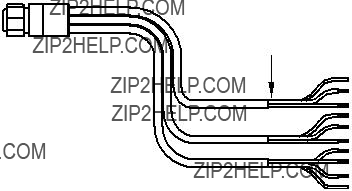
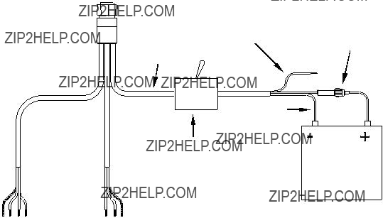
Your unit comes with a power/data cable that splits into three branches, each with several exposed wires.
The thicker
The thinner branch with three wires (red, black and shield) is the power cable for a NMEA 2000 network. It is labeled "NMEA 2000 POWER."
The branch with four wires (blue, yellow, orange, and shield) is a data cable, labeled
Display unit power wires: white, red and black
To unit
NMEA 2000 power wires:  red, black and shield
Data cable wires:  blue, yellow, orange,
and shield
The Power/Data cable for this unit.
NOTE:
There are two basic power connection options, which are shown in the following two diagrams. Read the following instructions carefully to determine which power connection applies to your unit. Depending on your configuration, you may not use all of these wires.
30
Caution:
All of the wires in the power/data cable have bare ends for eas- ier installation. The bare ends on any unused wires could cause an electrical short if left exposed. To prevent this, you should cover the individual wire ends ??? either by capping them with wire nuts, wrapping them with electrical tape or both. (You should cut off the bare wire before taping off the ends.)
Powering Your Display Unit
The display unit works from a
Caution:
We strongly recommend that you shut off the power supply to the power cable when the unit is not in use, especially in saltwater en- vironments. When the unit is turned off but still connected to a power supply, electrolysis can occur in the power cable plug. This may result in corrosion of the plug body along with the electrical contacts in the cable and the unit's power socket. Risk of electroly- sis corrosion is even greater when the cable is unplugged from the unit, but still connected to a power source.
We recommend you connect the power cable to the auxiliary power switch included in most boat designs. If that results in electrical interference, or if such a switch is not available, we recommend connecting direct to the battery and installing an
WARNING:
This product must be independently fused with the en- closed
If a malfunction happens inside the unit, extensive dam- age can occur if the enclosed fuse is not used. As with all electrical devices, this unit could be damaged to a point that it is unrepairable and could even cause harm to the user when not properly fused.
Failure to use a
31

If possible, keep the power cable away from other boat wiring, especially the engine's wires. This will provide the best isolation from electrical noise. If the cable is not long enough, splice #18 gauge wire onto it.
The display power cable has three wires, white, red and black. Red is the positive (+) lead, black is negative
For example, if you have to extend the power cable to the power bus or battery, attach one end of the fuse holder directly to the power bus or battery. This will protect both the unit and the power cable in the event of a short.
This unit has reverse polarity protection. No damage will occur if the power wires are reversed. However, the unit will not work until the wires are attached correctly.
Power Diagram A
Data Cable
Use this method if you are powering the display unit and a GPS mod- ule or the display unit and a NMEA 2000 network. (Fuses may be dif- ferent from those shown.).
The network and any NMEA 2000 devices, including the GPS module, will not operate unless the NMEA 2000 Power Cable is connected to power. The NMEA 2000 power cable must be connected
32
to power even if your only NMEA 2000 device is the GPS module and it is connected to the display unit's Network socket. (However, never connect multiple power sources to a NMEA 2000 network. If you have a network that is already powered, see diagram B on page 33.)
Power Diagram B
Use this method if you are only powering your display unit and are not powering a NMEA 2000 network or any NMEA 2000 accessory device, including a GPS module. (Fuse may be different from that shown.)
The method in diagram B is also used when your display unit is con- nected to a NMEA 2000 network that is already connected to power.
(Never connect multiple power sources to a NMEA 2000 network.)
Powering a NMEA 2000 Network Bus
A NMEA 2000 bus must be connected to a power source to operate. NMEA 2000 devices, including GPS modules, draw their power from the network bus.
If you have a
Never attach two power sources to a single NMEA 2000 bus.
33

If you do need to power your NMEA 2000 bus, attach the NMEA 2000 Power cable to an accessory switch as indicated in power diagram A on page 32. The NMEA 2000 Power cable's red wire should be attached (with provided
WARNING:
The NMEA 2000 network bus is always on and constantly drawing power. You must connect NMEA power to a switched power source so you can turn off the network when not in use. Failure to connect to and use a power switch will drain your boat battery, which could stop your boat's operation.
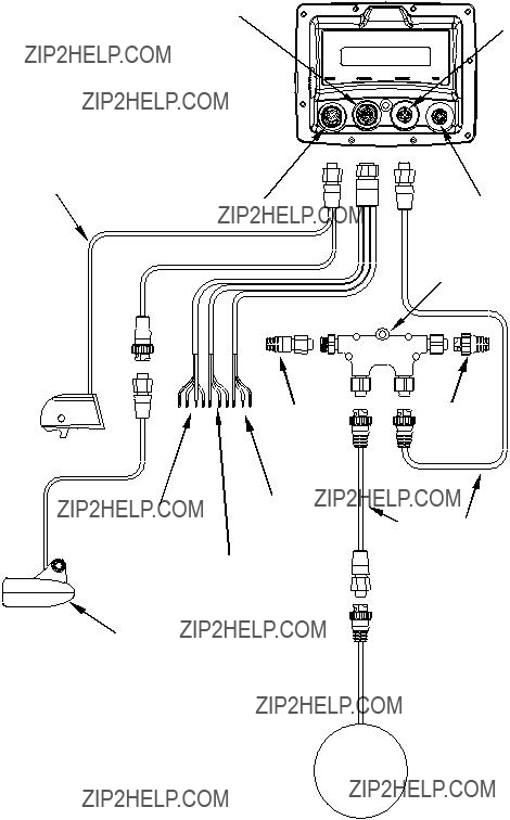
GPS Antenna/Receiver Module
The
You need to select an antenna installation location that has a clear, un- obstructed view of the sky. After the module is installed, connect it to the unit. The
NOTE
See the module???s instruction sheet, publication part number 988-
34
To use the module in an automobile, you may achieve good results by simply placing the external antenna on the top of the dash, at the base of the windshield. A piece of the rubber
Connecting to a NMEA 2000 Network
A network bus is an installed and operational network cable (backbone) running the length of your boat, already connected to a power supply and properly terminated. Such a bus provides network connection nodes at various locations around your boat. The NMEA 2000 network is similar to the telephone wiring in a house. If you pick up a phone in your living room, you can hear someone talking into the phone in the bedroom.
Lowrance and LEI provide all the cables you will need to create a NMEA 2000 network. Lowrance provides T connectors and extension cables so you can add devices along the backbone wherever you want. Once you have a working network, every sensor added will come with its own T connector for easy expansion.
The simplest NMEA 2000 network is a GPS or sonar/GPS display unit with the
35
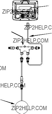
Network port on display unit
terminator 
 120-ohm
Extension cable 
The diagram has a double T connector with two
NMEA 0183 Wiring (Data cable)
To exchange NMEA 0183 data, this unit has one NMEA 0183 version 2.0 communication port. Com port one
The four wires for the com port are combined with the Power Supply cable and NMEA 2000 Power cable to form the power/data cable (shown earlier).
36

37
Double T connector
NMEA 2000
Power cable
Transducer
38
Mounting the Unit: Bracket,
You can install your unit on the dash with the gimbal bracket. It can also be installed in the dash or mounted on a portable power supply.
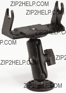
If you use the supplied bracket, you may be interested in the optional
Optional
Bracket Installation
Mount the unit in any convenient location, provided there is clearance behind it when it's tilted for the best viewing angle. You should also make sure there is enough room behind it to attach the power, transducer and GPS antenna/receiver module cables.
Holes in the bracket's base allow wood screw or
39

Front 
Install the gimbal bracket. Orient the bracket so the arms slope to- ward the front of your unit.
Drill a
173.9  [6.85]
137.9
[5.43]
Millimeter
[Inch]
72.9
[2.87]
23.4
[0.92]
157.9
[6.22]
56.9
[2.24]
Front view (left) and side view (right) showing dimensions of the LMS- 520c and
40
After drilling the hole, pass the transducer connector up through the hole from under the dash, followed by antenna connector. Pass the power cable's
If you wish, you can fill in the hole around the cables with a good ma- rine caulking compound. (Some marine dealers stock cable hole covers to conceal the opening.) No matter what type of installation you prefer, be sure to leave enough slack in the cables to allow tilting or swiveling the unit. If you choose to fill in the hole, be sure to position the cables against the rear edge of the hole as you apply the fill material.
Before positioning the bracket, be sure to hold the cables against the rear edge of the hole. Slide the bracket over the hole and butt the rear of the bracket base against the cables, thus pinning them in place against the side of the hole. Fasten the bracket to the dash. Attach the unit to the gimbal bracket using the gimbal knobs and washers.
You can mount the unit in the dash with an optional
146.5
[5.76]
Top
R 7.9 [0.31]
113.5
Template[4.46]
Millimeters
[Inches]
ALWAYS VERIFY DIMENSIONS
NOTE: The figure above is not printed to scale. A scaled template (FM- 5
41
Portable Installation
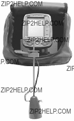
Like many Lowrance products, the unit is capable of portable operation by using an optional portable power pack. The power pack, a magnet- equipped antenna module and an optional portable transducer, ex- pands the uses for your sonar/GPS unit. It makes it easy to transfer your unit from a boat to a car, recreational vehicle, airplane or other vehicle without mounting a second bracket. You can use it in your own car or boat, then take it along when riding in a friend's vehicle.
The power pack can be used with eight "D" cell alkaline batteries or an optional sealed, rechargeable battery. Visit our web site for a complete listing of all the available portable power packs.
MMC or SD Card Memory Card Installation
Your unit uses a MultiMedia Card to store information, such as sonar logs, custom maps, waypoints, trails and other GPS data. It can also use Secure Digital Cards (SD card) to store data.
NOTE:
Throughout this manual, we will use the term MMC, but just re- member that your unit can use an MMC or SD card to store data.
42
Both of these
Additional MMC cards are available from LEI Extras; see ordering in- formation inside the back cover of this manual. MMCs and SD cards are also available at many camera and consumer electronics stores.
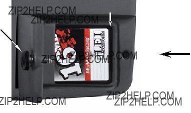
The MMC slot is located in a compartment on the front of the case. The compartment door is located at the lower right corner. The following figure shows a
MMC groove for card removal
Thumb
screw
Insert card face up, this way
Memory card compartment with a 16 MB MMC card installed.
To remove an MMC
1.Open the card compartment door by unscrewing the thumb screw. The screw should only be finger tight. If it was
2.Just press a finger against the label of the MMC and drag it from the slot.
3.Close the compartment door and fasten the thumb screw finger tight.
To add an MMC or SD Card
1.Open the card compartment door.
2.Grasp the bottom of the MMC and push the top of the card into the slot. Once the card is started, use your fingernails to slide it the rest of the way to the left, until it is firmly seated in the slot.
3.Close the compartment door and fasten the thumb screw finger tight.
43

Other Accessories
Cleaning Towel
A
If you lose the towel or wear it out, you can replace it with a similar microfiber cloth. These are often available where shop towels or auto- mobile cleaning towels are sold.
Caution:
Cleaning fabrics other than the microfiber towel type may scratch the screen. Polishing compounds or other abrasive cleaners will scratch the screen. Damage caused by incorrect cleaning is not cov- ered by the warranty. You may wash the towel if it becomes soiled or loses its effectiveness, but do not use fabric softener. Fabric sof- tener will ruin the towel???s cleaning capability.
Two switch boxes are available for this unit. The
If these accessories are not available from your dealer, see the acces- sory ordering information on the inside back cover of this manual. Visit our web site for a complete listing of all the available accessories.
MapCreate???
44
Now that you have your unit installed, move on to Section 3, Basic So- nar Operations. There, we'll present a series of
NOTE:
When you first turn the unit on, the Map Page appears. If you'd rather start learning about GPS operation first, turn over to Sec- tion 6, Basic GPS Operations.
Face Cover
Your unit comes with a white protective cover that snaps on and off the front of the unit. This cover is intended for use when the vehicle is idle.
WARNING:
When the unit is mounted in an unprotected area, such as an open boat cockpit, the protective face cover must be removed when the vehicle is moving at high speed. This includes towing a boat on a trailer at highway speeds. Otherwise, wind blast can pop off the cover.
45
Notes
46

Section 3: Basic Sonar Operation
This section addresses the unit's most basic sonar operations. Before you turn on the sonar unit, it's a good idea to learn about the different keys, the Main Menu, the four Page screens and how they all work to- gether. BUT, if you just can't wait to get on the water, turn to the one- page Quick Reference on page 55.
Keyboard
MMC slot access door
1.PWR/LIGHT (Power & Light) ??? The PWR key turns the unit on and off and activates the backlight.
2.PAGES ??? Pressing this and the ??? ??? arrow keys switches the unit between the four different page screens. (Satellite Status Page, Naviga- tion Page, Map Page and Sonar Page.) Each page represents one of the unit's major operation modes.
47
3.MENU ??? Press this key to show the menus and submenus, which allow you to select a command or adjust a feature. This also accesses search functions for streets, intersections, addresses and highway exits.
4.ARROW KEYS ??? These keys are used to navigate through the menus, make menu selections, move the map and sonar chart cursors and enter data.
5.ENT/ICONS (Enter & Icons) ??? This key allows you to save data, ac- cept values or execute menu commands. It is also used to create event marker icons.
6.EXIT ??? The Exit key lets you return to the previous screen, clear data or close a menu.
7.WPT ??? (Waypoint) The Waypoint key is used to save and recall way- points, search for waypoints and access the waypoint list. It also launches the
8.ZOUT ??? (Zoom Out) ??? This key lets you zoom the screen out. On the Sonar Page, it returns you to a full sonar chart display, showing the entire water column from surface to bottom. On the Map Page, it lets you see a larger geographic area on the map. Less detail is seen as you zoom out.
9.ZIN ??? (Zoom In) ??? This key lets you zoom the screen in. On the Sonar Page, this key enlarges fish signals and bottom detail. On the Map Page, zooming in lets you see greater detail in a smaller geographic area on the map.
Power/lights on and off
To turn on the unit, press PWR. As the unit powers up, the Map Page is displayed first. To switch to the Sonar Page, press PAGES, select SONAR and press ENT.
To turn on the backlight, press PWR again. The unit has three back- light levels. Repeatedly pressing PWR will cycle through the backlight settings and turn off the backlight.
Turn off the unit by pressing and holding the PWR key for 3 seconds.
Main Menu
The unit has a Main Menu, which contains some function commands and some setup option commands. The instructions in this section will deal only with sonar functions, the basic commands that make the unit show sonar signals on your screen. This sonar unit will work fine right out of the box with the factory default settings.
48
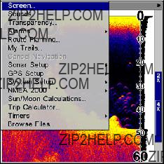
You can access the Main Menu from any of the four Page screens by pressing MENU|MENU. To clear the menu screen and return to the page display, press EXIT.
Main Menu.
The Main Menu commands and their functions are:
Screen: changes the contrast or brightness of the display screen.
Sounds: enables or disables the sounds for key strokes and alarms and sets the alarm style.
Transparency: adjusts the level of transparency for menus.
Alarms: turns sonar and GPS alarms on or off and changes alarm thresholds.
Route Planning: used to plan, view or navigate a route.
My Trails: shows, creates and deletes plot trails. Also used to navigate or backtrack a trail.
Cancel Navigation: turns off the various navigation commands. Used to stop navigating after you have reached your destination waypoint, Point of Interest or map cursor location; or after you reach the end of a route or trail.
Sonar Setup: sets various sonar options.
GPS Setup: sets various GPS receiver options.
System Setup: sets general configuration options.
NMEA 2000: provides access to all NMEA 2000 network setup options, including the configuration of devices on the network. For more infor- mation, see Section 10: NMEA 2000 Menu.
Sun/Moon Calculations: finds the rising and setting time of the sun and the moon.
Trip Calculator: shows trip status and statistics.
49

Timers: controls the up timer, down timer and alarm clock settings.
Browse MMC Files: this allows you to view the installed MMC card and the files it contains.
Pages
The unit has five Page displays that represent the four major operating modes. They are the Satellite Status Page, the Navigation Page, the Map Page and Sonar Page. They are accessed by pressing the PAGES key, then using ??? ??? to select a Page. (Clear the Pages Menu by pressing
EXIT.)
Pages Menu showing Sonar display options.
Satellite Status Page
The Satellite Status Page provides detailed information on the status of the unit's satellite
This page represents a GPS function, so it is discussed in much greater detail in Sec. 6.
No matter what Page you are on, a flashing current position indica- tor/question mark symbol and flashing GPS data displays indicate that satellite lock has been lost and there is no position confirmed.
WARNING:
Do not begin navigating with this unit until the numbers have stopped flashing!
50
Satellite Status Page.
Navigation Page
This screen has a compass rose that not only shows your direction of travel, but also the direction to a recalled waypoint. To get to the Navi- gation Page: Press PAGES| ??? or ??? to NAVIGATION|EXIT.
This page represents a GPS function, but also has a navigation with sonar option, which will keep you updated on what is under your boat as well as where you???re going.
Navigation page with Sonar (left). Navigation Page with digital data (right).
Map Page
The Map Page screens show your course and track from a
51
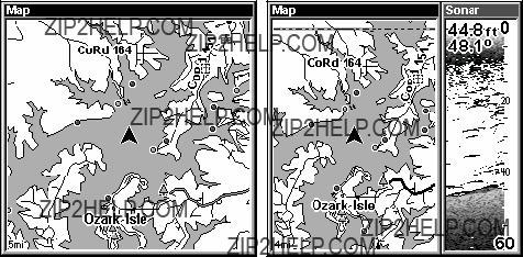
Map Pages, showing position on Bull Shoals Lake, Arkansas. The full map option (left). Map with sonar option (right).
Map Page is also the default screen that appears when you turn on the unit. To get to the Map Page from another page: Press PAGES| ??? or ???
to MAP|EXIT.
You can display a split screen showing both the Map and Sonar pages at the same time. This feature is discussed in Sec. 4, Sonar Options & Other Features.
The Map Page represents a GPS function, so it is discussed in much greater detail in Sec. 6.
Sonar Page
The Sonar Page displays the sonar chart. This is a
To get to the Sonar Page: Press the PAGES key, then use ??? or ??? to se- lect SONAR. (Clear the Pages Menu by pressing EXIT.) The Pages Menu also offers five chart display options under the Sonar Page category. To access them, press PAGES|??? or??? to SONAR|??? to Option Name|EXIT.
The Sonar Page also has its own menu, which is used for some advanced functions and for setting various options. (Sonar Options and other fea- tures are discussed in Sec. 4.) To Access the Sonar Page menu, from the Sonar Page press MENU.
52
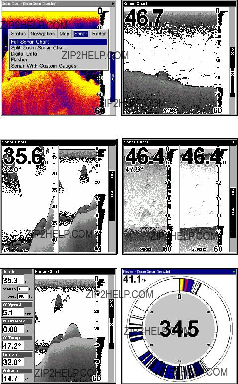
Pages Menu (left) showing sonar chart display option commands. Sonar Page in full sonar chart display mode (right).
Split Zoom page (left) and Split Frequency page (right).
Digital Data page (left) and Flasher page (right).
53
Sonar Page showing full sonar chart mode.
You can customize how the Sonar Page displays its pictures and other data in many ways.
We'll discuss all of those features and options in Sec. 4, but to show you how easy this unit is to operate, the following page contains a simpli- fied,
54
Basic Sonar Quick Reference
1.Depress the PWR key to turn on the unit.
2.Opening screen displays Map Page. Rotate through the four main Page screens (Map Page, Satellite Status Page, Navigation Page, Sonar
Page) by pressing PAGES|??? or ??? to select Page Name|EXIT. Switch Pages to display Sonar Page.
3.If GPS data is desired, wait while unit locates satellites and calculates current position. When the unit acquires position, a tone sounds and a posi- tion acquired message appears.
4.With position acquired (if desired), head for your fishing grounds. Your unit will automatically display digital depth and surface water temperature in the top left corner of the screen.
The auto settings will track the bottom, displaying it in the lower por- tion of the screen. The full sonar chart will scroll from right to left, showing you what's under the boat as you cruise across the water. You can change the display by:
Zoom in to enlarge the chart for more detail: press ZIN.
Zoom out to return to full chart mode: press ZOUT.
5.Watch the display for the appearance of fish symbols (or arches, if Fish I.D.??? is turned off). When you see fish symbols or arches, you've found fish! Stop the boat and get your lure or bait into the water at the depth indicated on the sonar chart.
6.Gauge the fish depth by visually comparing the fish symbols or arches with the depth scale on the right side of the screen.
7.If you are drifting at a very low speed or anchored, you are not mov- ing fast enough for a fish to return the
8.To turn off the unit, press and hold PWR key for three seconds.
55
Sonar Operations
As you can see from the quick reference on the previous page, basic operation is pretty easy, right out of the box. If you are a sonar novice, try operating the unit with the factory defaults until you get a feel for how it's working.
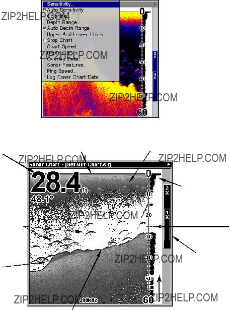
As you're learning the basics, there is one setting you might want to tinker with from time to time ??? Sensitivity.
Sensitivity controls the unit's ability to pick up echoes. If you want to see more detail, try increasing the sensitivity, a little at a time. There are situa- tions when too much clutter appears on the screen. Decreasing the sensitivity can reduce the clutter and show the strongest fish echoes, if fish are present. As you change the sensitivity setting, you can see the difference on the chart as it scrolls.
These figures show results of different sensitivity levels on the same loca- tion. Fig. 1: Sensitivity at 88 percent, determined by Auto Sensitivity.
Typical of full auto mode. Fig. 2: Sensitivity set at 75 percent. Fig. 3: Sen- sitivity set at 50 percent. Fig. 4: Sensitivity set at 100 percent.
56

You can change the sensitivity level whether you are in Auto Sensitivity mode or Manual Sensitivity mode. The adjustment method works the same in both modes, but it gives you slightly different results.
Adjusting sensitivity in Auto Sensitivity Mode is similar to manually ad- justing a car's speed with the accelerator pedal while cruise control is on. You can tell the car to run faster, but when you let off the gas the cruise control automatically keeps you from running slower than the minimum speed setting. In the unit, auto mode will let you increase sensitivity to 100 percent, but the unit will limit your minimum setting. This prevents you from turning sensitivity down too low to allow automatic bottom tracking. When you change the setting with auto turned on, the unit will continue to track the bottom and make minor adjustments to the sensitiv- ity level, with a bias toward the setting you selected.
Adjusting sensitivity in Manual Sensitivity Mode is similar to driving a car without cruise control ??? you have complete manual control of the car's speed. In the unit, manual mode allows you to set sensitivity at 100 percent (maximum) or zero percent (minimum.) Depending on wa- ter conditions, the bottom signal may completely disappear from the screen when you reduce sensitivity to about 50 percent or less!
Try adjusting sensitivity in both auto and manual modes to see how they work.
To adjust sensitivity:
1.Press MENU|ENT.
2.The Sensitivity Control Bar appears. Press ??? to decrease sensitivity; press ??? to increase sensitivity. When it's set at the desired level, press EXIT. (When you reach the maximum or minimum limit, a tone sounds.)
Sonar Menu with Sensitivity command selected (left). The Sensitivity Control Bar (right).
57
NOTE:
If you want to change the sensitivity in Manual Mode, first turn off Auto Sensitivity: from the Sonar Page, press MENU|??? to AUTO SENSI- TIVITY|ENT|??? to SENSITIVITY|ENT. Press ??? or ??? to pick a different sen- sitivity setting. When it's set at the desired level, press EXIT.
Important Tip:
While you are experimenting and learning, it's possible to scramble the settings so that the sonar picture disappears from your screen. If that happens, remember that it's easy to switch back to full automatic operation by simply restoring the factory auto settings.
To Restore Factory Settings:
1.Press MENU|MENU|??? to SYSTEM SETUP|ENT|??? to RESET OPTIONS|ENT.
2.The unit asks if you want to reset all the options. Press ??? to YES|ENT. All options are reset, and the unit reverts back to the Map Page at the 4000 mile zoom range. (Any recorded sonar logs or GPS data will be unchanged.)
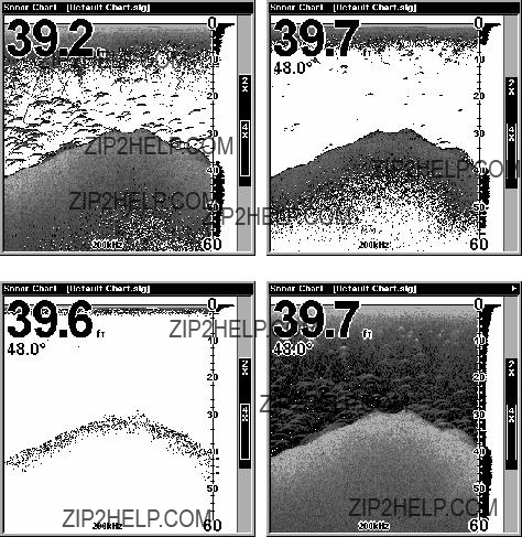
Fish Symbols vs. Full Sonar Chart
You may have noticed in the quick reference that we used fish arches in full sonar chart mode for our example, and not the popular Fish I.D.??? fish symbol feature. Here's why.
Fish I.D. is an easier way for a sonar novice to recognize a fishy signal return when he sees it. However, locating fish by symbol only has some limitations.
Your sonar unit's microprocessor is remarkably powerful, but it can be fooled. Some of the echoes calculated to be fish could be tree limbs or tur- tles! To see what's under your boat in maximum detail, we recommend you turn off Fish I.D. and begin learning to interpret fish arches.
Fish I.D. is most handy when you're in another part of the boat or per- forming some task that prevents you from watching the sonar screen. Then, you can turn on Fish I.D. and the audible fish alarm. When that lunker swims under your boat, you'll hear it!
Fish I.D. can also be useful when you want to screen out some of the sonar detail gathered by your unit. For example, in one case fisherman in San Francisco Bay saw clouds of clutter in the water but no fish arches. When a down rigger was pulled up, it brought up several small jellyfish. The fisherman switched their sonar to Fish I.D., which screened out the schools of jellyfish and clearly showed the game fish there as fish symbols.
58
Other Free Training Aids
The sonar options section discusses Fish I.D., fish alarms and other features in greater detail. If you or a friend has Internet access, you can also learn more about interpreting what you see on your sonar screen. Visit our web site, www.lowrance.com. Be sure to check out the free Sonar Tutorial, which includes animated illustrations and more pic- tures of actual sonar returns, all described in detail. There's even a "printer friendly" version of the tutorial available on our web site???it makes a great supplement to this operation manual!
You can also download a free copy of our Sonar Viewer software. This
???Adjustable range, zoom, sensitivity, color line, noise rejection, surface clarity, etc. of the recorded file.
???Color interpretation of sonar signals can be user defined.
???Operates like a Windows Multimedia Player with forward, re- verse, pause, fast forward, fast reverse, and scroll buttons.
???Adjustments update the entire record displayed.
???Can print in full color.
???Window can dynamically be sized on your monitor.
???Mouse cursor shows GPS position, depth and sounding number anywhere on the visible record.
For the ultimate training aid, be sure to download the free emulator software for your unit. Aside from being fun, this program can help you learn both basic and advanced operations without burning boat fuel! Lowrance is one of the first sonar manufacturers to provide this type of training tool for customers.
This PC application simulates the actual sonar/GPS unit on your com- puter. You can run it from your computer keyboard or use your mouse to press the virtual keys. Easy download and installation instructions are available on our web site.
59
Free training emulator is available for your unit on our web site.
The emulator works exactly like your real sonar/GPS unit. Using the Sonar Simulator and GPS Simulator features, it allows you to play back sonar logs, run GPS routes and trails and create real waypoints you can use in the field! You can even take snapshots of the Sonar Chart and print them or
60
Section 4: Sonar Options
ASP??? (Advanced Signal Processing)
The ASP??? feature is a noise rejection system built into the sonar unit that constantly evaluates the effects of boat speed, water conditions and interference. This automatic feature gives you the best display pos- sible under most conditions.
The ASP feature is an effective tool in combating noise. In sonar terms, noise is any undesired signal. It is caused by electrical and mechanical sources such as bilge pumps, engine ignition systems and wiring, air bubbles passing over the face of the transducer, even vibration from the engine. In all cases, noise can produce unwanted marks on the display.
The ASP feature has four settings ??? Off, Low, Medium and High. If you have high noise levels, try using the "High" ASP setting. However, if you are having trouble with noise, we suggest that you take steps to find the interference source and fix it, rather than continually using the unit with the high ASP setting.
There are times when you may want to turn the ASP feature off. This allows you to view all incoming echoes before they are processed by the ASP feature.
Sonar Menu with Sonar Features highlighted (left). Sonar Features menu (right) with Noise Rejection (ASP) set to default low setting.
To change the ASP level:
1.From the Sonar Page, press MENU|??? to SONAR FEATURES|ENT.
2.Press ??? to NOISE REJECTION|ENT.
3.Press ??? or ??? to select a setting, then press ENT.
4.To return to the previous page, press EXIT|EXIT.
61

Alarms
This unit has three different types of sonar alarms. The first is the Fish Alarm. It sounds when the Fish I.D.??? feature determines that an echo is a fish.
Another alarm is the Zone Alarm, which consists of a bar on the side of the screen. Any echo on the chart that appears inside this bar triggers this alarm.
The last alarm is the Depth Alarm, which has both a Shallow and a Deep setting. Only the bottom signal will trigger this alarm. This is useful as an anchor watch, a shallow water alert or for navigation.
Depth Alarms
The depth alarms sound a tone when the bottom signal goes shallower than the shallow alarm's setting or deeper than the deep alarm's set- ting. For example, if you set the shallow alarm to 10 feet, the alarm will sound a tone if the bottom signal is less than 10 feet. It will con- tinue to sound until the bottom goes deeper than 10 feet.
The deep alarm works just the opposite. It sounds a warning tone if the bottom depth goes deeper than the alarm's setting. Both depth alarms work only off the digital bottom depth signals. No other targets will trip these alarms. These alarms can be used at the same time or individually.
Main Menu with GPS Alarms selected (left). Sonar Alarms menu (right).
To adjust and turn on the shallow alarm:
1.Press MENU|MENU|??? to ALARMS|ENT|??? to SONAR ALARMS|ENT.
2.Press ??? to SHALLOW ALARM DEPTH|ENT.
62
3.Press ??? or ??? to change the first number, then press ??? to move the cursor to the next number and repeat until the depth is correct, then press ENT.
4.Press ??? to SHALLOW ALARM ENABLED|ENT|EXIT|EXIT|EXIT.
5.To turn off the alarm, press MENU|MENU|??? to ALARMS|ENT|??? to SO-
NAR ALARMS|ENT|ENT|EXIT|EXIT|EXIT.
To switch to a different depth setting, open the Sonar Alarms menu and repeat the instructions in step 3 above.
To adjust and turn on the deep alarm:
1.Press MENU|MENU|??? to ALARMS|ENT|??? to SONAR ALARMS|ENT.
2.Press ??? to DEEP ALARM ENABLED|??? to DEEP ALARM DEPTH|ENT.
3.Press ??? or ??? to change the first number, then press ??? to move the cursor to the next number and repeat until the depth is correct, then press ENT.
4.Press ??? to DEEP ALARM ENABLED|ENT|EXIT|EXIT|EXIT.
5.To turn off the alarm, press MENU|MENU|??? to ALARMS|ENT|??? to SO-
NAR ALARMS|ENT|??? to DEEP ALARM ENABLED|ENT|EXIT|EXIT|EXIT.
To switch to a different depth setting, open the Sonar Alarms menu and repeat the instructions in step 3 above.
Zone Alarm
The zone alarm is triggered when any echo passes inside the zone alarm bar, shown on the right side of the screen.
To adjust and turn on the zone alarm:
1.Press MENU|MENU|??? to ALARMS|ENT|??? to SONAR ALARMS|ENT.
2.Press ??? to ZONE ALARM ENABLED|??? to ADJUST ZONE|ENT.
63

Sonar Alarms menu with Adjust Zone command selected (left). Adjust Zone Alarm selection box with Upper selected (right).
3.To set the upper boundary for the Zone Alarm, use ??? or??? to select UPPER, then press ??? or ??? to move the top of the bar to the desired depth.
4.To set the lower boundary for the Zone Alarm, use ??? or??? to select LOWER, then press ??? or ??? to move the bottom of the bar to the desired depth.
5.Press EXIT|??? to ZONE ALARM ENABLED|ENT|EXIT|EXIT|EXIT. Now, any echo ??? fish, bottom, structure ??? within the zone alarm's depth range will trigger the zone alarm.
6.To turn off the alarm, press MENU|MENU|??? to ALARMS|ENT|??? to SO-
NAR ALARMS|ENT|??? to ZONE ALARM ENABLED|ENT|EXIT|EXIT|EXIT.
To switch to a different depth setting, open the Sonar Alarms menu and repeat the instructions in steps 3 and 4 above.
Fish Alarm
Use the fish alarm for a distinctive audible alarm when fish or other suspended objects are detected by the Fish I.D.??? feature (Fish I.D. must be turned on for the Fish Alarm to work). A different tone sounds for each fish symbol size shown on the display.
64

Sonar Alarms menu with Fish Alarm selected. The check box to the left is blank, indicating the alarm is turned off.
To turn on fish alarm:
1.Press MENU|MENU|??? to ALARMS|ENT|??? to SONAR ALARMS|ENT.
2.Press ??? to FISH ALARM|ENT|EXIT|EXIT|EXIT.
3.To turn off the alarm, press MENU|MENU|??? to ALARMS|ENT|??? to SO-
NAR ALARMS|ENT|??? to FISH ALARM|ENT|EXIT|EXIT|EXIT.
GPS Alarms
You can set an arrival alarm to flash a warning message and sound a tone when you cross a preset distance from a waypoint. For example, if you have the arrival alarm set to .1 mile, then the alarm will flash a message when you come within .1 mile of the recalled waypoint.
GPS Alarm highlighted on Alarms menu (left). GPS Alarms menu (right).
The off course alarm warns you when your track drifts too far to the right or left of the course line to the waypoint. For example, if the alarm is set to .1 mile, then the alarm flashes a message if you drift .1 miles to the right or left of the line to the waypoint.
65
The anchor alarm is triggered when you drift outside of a preset radius. Using the .1 mile as an example, if you're anchored and the boat moves more than .1 miles, a tone will sound and a message will appear.
1.To set an alarm, press MENU|MENU|??? to ALARMS|ENT|ENT.
2.Use ??? ??? to select the desired category, then press ENT to turn on (check) or turn off (uncheck) the desired Alarm Enabled box.
3.To change distance settings, use ??? ??? to select the desired category, then press ???|ENT to activate the distance dialog box. Press ??? ??? to change the first character, then press ??? to the next character and re- peat until the distance is set.
4.When the adjustments are finished, return to the main page display by repeatedly pressing EXIT.
IMPORTANT ALARM NOTES
Anchor Alarm - The anchor alarm may be triggered even when you're sitting still. This can happen when using a small (less than
.05 mile) anchor alarm range.
Arrival Alarm - If you set the arrival alarm's distance to a small number and you run a route (see the Navigate Routes segment), this unit may not show navigation data to the next waypoint, once you arrive at the first one. You may not be able to come close enough to the first waypoint to trip the arrival alarm.
NMEA 2000 Alarms
The NMEA 2000 Alarm can be set to monitor multiple
To get to the NMEA 2000 Alarms menu, press MENU|MENU, select ALARMS and press ENT. Choose NMEA 2000 ALARMS and press ENT.
1.With the Fluid Level Device window highlighted, press ENT and use ??? ??? to select the device you want to monitor, then press ENT.
2.To enable the Full Alarm, highlight FULL ALARM Enabled box and press ENT to turn on (check) the alarm. Press ??? to the Percent box and press ENT. Use the ??? ??? keys to select the first number, then press ??? to move to the next number. When the desired percentage has been en- tered, press ENT.
66
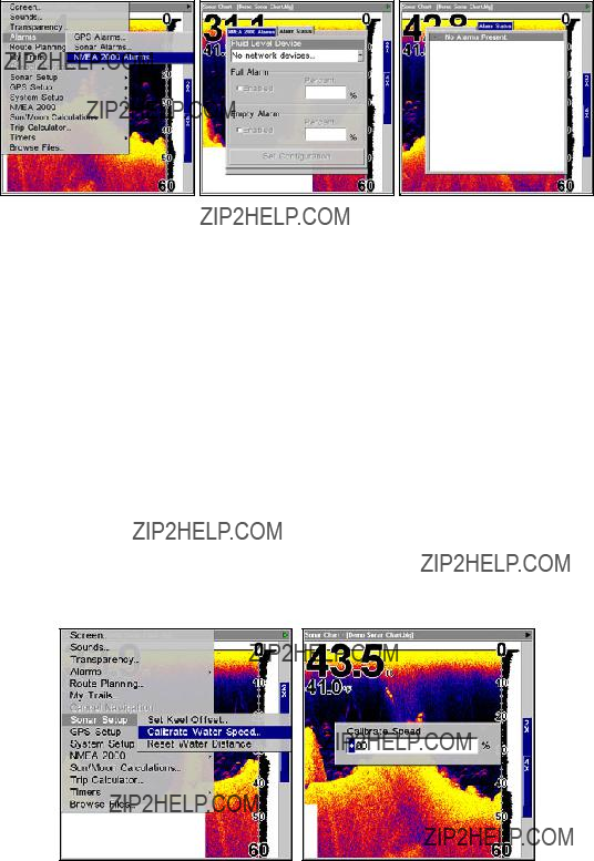
NMEA 2000 Alarms highlighted on Alarms menu (left). NMEA 2000 Alarms menu (center). Alarm Status page (right).
3. To enable the Empty Alarm, highlight the EMPTY ALARM Enabled box and press ENT to turn on (check) the alarm. Press ??? to the Percent box and press ENT. Use the ??? ??? keys to select the first number, then press ??? to move to the next number. When the desired percentage has been en- tered, press ENT.
Tip
You do not have to set both the Full and Empty alarms. Choose both Full and Empty alarms or activate them individually.
Calibrate Speed
The speed sensor can be calibrated to compensate for inaccuracies. Be- fore you change the setting, first calculate the percentage that the speed is off. You will enter this percentage in a moment.
If, for example, you figure the sensor is reading 10 percent faster than actual speed, you will enter ??? 10 in the calibration window. If the sen- sor is reading 5 percent slower than true speed, you will enter + 5 in the window.
Calibrate Water Speed highlighted on Sonar Setup menu (left). Cali- brate Speed dialog box (right).
67
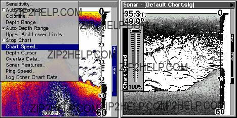
A good way to gauge your speed sensor's performance is to compare its reading with the ground speed measured by your unit's GPS functions. When you make a run to compare GPS ground speed to speed sensor speed, perform your test in relatively calm water free of current, if pos- sible. (Unless, of course, you are taking the speed of current into con- sideration when making your calculation.) After you have a correction figure, here's how to enter it:
1.Press MENU|MENU|??? to SONAR SETUP|ENT|??? to CALIBRATE WATER
SPEED|ENT.
2.Enter the number you calculated earlier: press ??? or ??? to change the first character (+ or
Chart Speed
The rate that echoes scroll across the screen is called the chart speed. The default is maximum; we recommend that you leave the speed set there for virtually all fishing conditions.
You, however, might consider experimenting with chart speed when you are stationary or drifting very slowly. You may sometimes achieve better images as you slow down the chart speed to match how fast you are moving across the bottom.
If you are at anchor, ice fishing or fishing from a dock, experiment with a chart speed around 50 percent. If you are drifting slowly, try a chart speed around 75 percent. When you are stationary and a fish swims through the sonar signal cone, the image appears on the screen as a long line instead of a fish arch. Reducing the chart speed may result in a shorter line that more closely resembles a regular fish return.
Sonar Page menu with Chart Speed command selected (left). Chart Speed Control Bar (right).
68

If you do experiment with chart speed, remember to reset it to maxi- mum when you resume trolling or moving across the water at higher speed.
To change chart speed:
1.From the Sonar Page, press MENU|??? to CHART SPEED|ENT.
2.The Chart Speed Control Bar appears. Press ??? to decrease chart speed; press ??? to increase chart speed.
3.When it's set at the desired level, press EXIT.
Colorline???
Colorline lets you distinguish between strong and weak echoes. It "paints" a brighter color on targets that are stronger than a preset value. This allows you to tell the difference between a hard and soft bottom. For example, a soft, muddy or weedy bottom returns a weaker signal which is shown with a narrow, colored line (dark blue tinged with red or a little yellow.) Since fish are among the weakest echoes, they show up mostly as blue arches. A hard bottom or other relatively hard target returns a strong signal which causes a wider brightly col- ored line (reddish yellow to bright yellow.)
If you have two signals of equal size, one with red to yellow color and the other without, then the target with brighter color (yellow) is the stronger signal. This helps distinguish weeds from trees on the bottom, or fish from structure.
Colorline is adjustable. Experiment with your unit to find the Color- Line setting that's best for you.
Sonar Page menu with ColorLine command selected (left). The Colorline control bar (right).
69
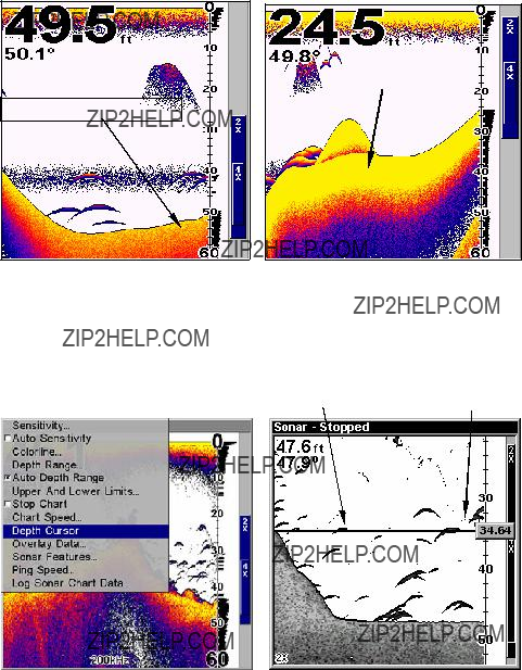
To adjust Colorline level:
1.From the Sonar Page, press MENU|??? to COLORLINE|ENT.
2.The ColorLine Control Bar appears. Press ??? to decrease ColorLine; press ??? to increase ColorLine.
3.When it's set at the desired level, press EXIT.
Wider
ColorLine
Thin or no ColorLine
A small amount of Colorline (left) is indicative of a soft bottom. A wider patch of Colorline indicates a harder bottom (right).
Depth Cursor
The depth cursor consists of a horizontal line with a digital depth box on the right side. The numbers inside the box show the depth of the
Sonar Page menu with Depth Cursor selected (left). Sonar chart with active depth cursor (right). The cursor is set at 34.64 feet deep.
70
The cursor can be moved to any location on the screen, letting you pin- point the depth of a target.
1.From the Sonar Page, press MENU|??? to DEPTH CURSOR|ENT.
2.The depth cursor appears. Press ??? to lower the cursor line; press ??? to raise the cursor line.
3.To clear the depth cursor, press EXIT.
Depth Range - Automatic
When turned on for the first time, the bottom signal is automatically placed in the lower half of the screen. This is called Auto Ranging and is part of the automatic function. However, depending upon the bottom depth and the current range, you can change the range to a different depth.
Sonar Page menu with Depth Range selected (left). Depth Range Con- trol Scale (right).
1.From the Sonar Page, press MENU|??? to DEPTH RANGE|ENT.
2.The Depth Range Control Scale appears. Press ??? or ??? to select a dif- ferent depth range. A blue bar highlights the selected range. The light numbers cannot be selected.
3.When the new range is selected, press EXIT to clear the menu.
Depth Range - Manual
You have complete control over the range when the unit is in the man- ual mode. There are 16 depth ranges, from 5 feet to 4,000 feet.
To switch to Manual Depth Range:
1.First, turn off automatic depth range. From the Sonar Page, press
MENU|??? to AUTO DEPTH RANGE|ENT.
2.Press ??? to DEPTH RANGE|ENT and the Depth Range Control Scale ap- pears.
71
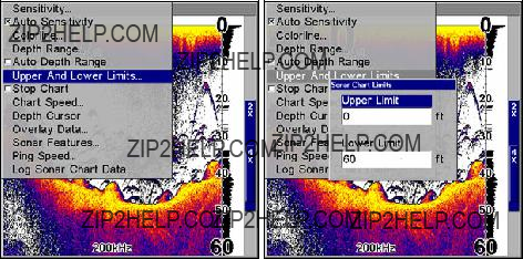
3.Press ??? or ??? to select a different depth range. A horizontal blue bar highlights the selected range.
4.When the new range is selected, press EXIT to clear the menu. Repeat these steps to turn on Auto Depth Range.
NOTE:
The sonar's depth capability depends on the water, bottom condi- tions, transducer installation and other factors.
Depth Range - Upper and Lower Limits
Virtually any segment of the water column can be displayed by using the upper and lower limit feature. This lets you pick the shallow and deep depth range limits that are shown on the screen, provided there is at least 10 feet between the upper and lower limit you select. For ex- ample, a range from 12 feet to 34 feet could be used.
Changing the upper and lower limits gives you far greater control over the depth range. This feature lets you "zoom in" the display in almost unlimited combinations. Nearly any segment of the water column, from the surface to the bottom can be shown.
Sonar Page Menu with Upper and Lower Limits selected (left). Sonar Chart Limits menu with Upper Limit selected (right).
To change the upper and lower limits:
1.From the Sonar Page, press MENU|??? to UPPER AND LOWER LIMITS|ENT. The Sonar Chart Limits menu appears, with Upper Limit selected.
2.To set the upper limit, press ENT. Press ??? or ??? to change the first number, then press ??? to move the cursor to the next number and re- peat until the depth is correct, then press EXIT.
72
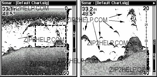
3. To set the lower limit, press ??? to LOWER LIMIT|ENT. Press ??? ??? to change the first number, then press ??? to move the cursor to the next number and repeat until the depth is correct, then press EXIT repeatedly.
Fish arches
Area "zoomed"
Normal display, in auto depth range mode (left). Display "zoomed" with Upper and Lower Limits focusing on the portion of the water column from 20 feet to 40 feet deep (right). In the "zoomed" image, note the target definition at lower left, showing a fish holding just above the structure.
To turn off upper and lower limits:
From the Sonar Page, press MENU|??? to AUTO DEPTH RANGE|ENT|EXIT.
FasTrack???
This feature automatically converts all echoes to short horizontal lines on the display's far right side. The graph on the rest of the screen con- tinues to operate normally. FasTrack gives you a rapid update of condi- tions directly under the boat. This makes it useful for ice fishing, or when you are fishing at anchor. When the boat is not moving, fish sig- nals are long, drawn out lines on a normal chart display. FasTrack con- verts the graph to a vertical bar graph that, with practice, makes a use- ful addition to fishing at a stationary location.
73

Surface clutter
Fish arches
Structure
In FasTrack, fish arches show as horizontal bars.
Bottom signal
FasTrack
Sonar Page showing FasTrack. bar graph
Fish I.D.??? (Fish Symbols & Depths)
The Fish I.D. feature identifies targets that meet certain conditions as fish. The microcomputer analyzes all echoes and eliminates surface clutter, thermoclines, and other signals that are undesirable. In most instances, remaining targets are fish. The Fish I.D. feature displays fish symbols on the screen in place of the actual fish echoes.
There are several fish symbol sizes. These are used to designate the relative size between targets. In other words, Fish I.D. displays a small fish symbol when it thinks a target is a small fish, a medium fish sym- bol on a larger target and so on.
The sonar's microcomputer is sophisticated, but it can be fooled. It can't distinguish between fish and other suspended objects such as trotlines, turtles, submerged floats, air bubbles, etc. Individual tree limbs ex- tending outwards from a group of limbs is the hardest object for the Fish I.D. feature to distinguish from fish.
You may see fish symbols on the screen when actually, there are no fish. The reverse is also true. The illustrations on the next page show how Fish I.D. can actually miss fish that are present.
Does that mean Fish I.D. is broken? No ??? the feature is simply inter- preting sonar returns in a specific way to help take some of the work out of reading the screen. Remember: Fish I.D. is one of the many tools we provide so you can analyze your sonar returns for maximum fish finding information. This and other features can help you successfully "see" beneath the boat under varied water and fishing conditions. So, practice with the unit in both the Fish I.D. mode and without to become more familiar with the feature. The default for Fish I.D. is off.
74
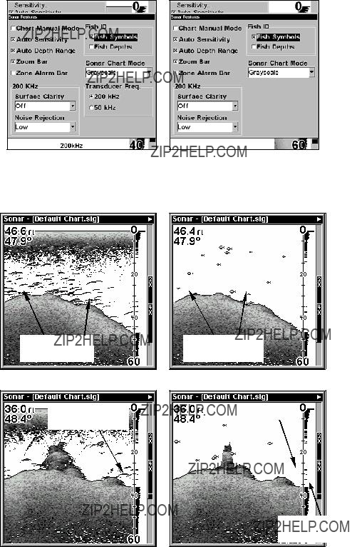
Sonar Features menu with Fish I.D. Symbols selected on dual- frequency menu (left);
Many fish arches visible
Fig. 2 A
Fish arches above structure
Fewer fish symbols visible
Fig. 2 B
No fish shown
FasTrack graph confirms fish
Figures 1A and 2A show Sonar Page in normal chart mode (left). Figures 1B and 2B (right) show the same underwater scene with Fish I.D. turned on. Note how arches are replaced with symbols.
75
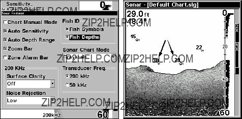
To turn the Fish I.D. feature on:
1.From the Sonar Page, press MENU|??? to SONAR FEATURES|ENT.
2.Press ??? to FISH SYMBOLS|ENT|EXIT|EXIT.
To turn off Fish I.D., repeat the instructions in step 2.
FishTrack???
The FishTrack feature shows the depth of a fish symbol when it ap- pears on the display. This lets you accurately gauge the depth of tar- gets. This feature is available only when the Fish I.D. feature is on. The default setting for FishTrack is off.
To turn on FishTrack:
(Note: These instructions will turn on FishTrack and Fish I.D. at the same time.)
1.From the Sonar Page, press MENU|??? to SONAR FEATURES|ENT.
2.Press ???|then press ??? to FISH DEPTHS|ENT|EXIT|EXIT.
To turn off FishTrack, repeat the instructions in step 1. Turning off FishTrack in this manner will not turn off Fish I.D. symbols.
Symbols with
FishTrack depths
Sonar Features menu with Fish I.D. Depths selected on
Sonar Page with Fish I.D. symbols and FishTrack depths turned on (right).
Frequency (Change Transducer Frequency)
The
76
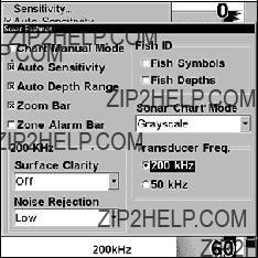
The default frequency is 200 kHz, which is best for use in shallow wa- ter (about 300 feet or less). This frequency is the best choice for about 80 percent of the fresh and salt water sport fishing applications. When you get into very deep salt water, 300 to 500 feet or deeper, the 50 kHz frequency is the best choice.
The 200 kHz transducer will give you better detail and definition, but less depth penetration. The 50 kHz transducer will give you greater depth penetration, but a little less detail and less definition. (Remember, all sonar units typically read deeper in fresh water than in salt water.)
There is a common exception to these rules of thumb. Some fishermen on freshwater lakes (or the ocean) using downriggers like to see them on the sonar. In many of those cases, you'll see a 50 kHz transducer frequency in use because the wider cone angle lets them watch the bait.
Sonar Features menu with a frequency of 200 kHz selected.
To change the frequency setting to 50 kHz:
1.From the Sonar Page, press MENU|??? to SONAR FEATURES|ENT.
2.Press ???|then press ??? to 50 KHZ|ENT.
3.Press EXIT|EXIT to clear the menu.
To change the frequency setting to 200 kHz:
1.From the Sonar Page, press MENU|??? to SONAR FEATURES|ENT.
2.Press ???|then press ??? to 200 KHZ|ENT.
3.Press EXIT|EXIT to clear the menu.
HyperScroll???
See the entry on Ping Speed, which controls the HyperScroll feature.
77

Log Sonar Chart Data
If you have an MMC installed in the unit, the sonar data shown on the screen can be saved to the MMC. This can be played back at any time (to play a recorded sonar chart log, see the entry in this section for So- nar Simulator). If you have a personal computer and Internet access, visit our web site, www.lowrance.com, and download the free Sonar Viewer and the emulator for your unit. These programs will allow you to replay sonar logs on your personal computer.
Sonar Page menu with the Log Sonar Chart Data selected (left). Sonar Chart Logging menu (right) with the Start Logging selected. The menu says the MMC has 5.42 MB of free space, which will record the scroll- ing chart for 28 minutes and 44 seconds.
To record or log chart data:
1.Press MENU|??? to LOG SONAR CHART DATA|ENT.
2.To record data using the default settings, press ENT. The menu clears and the Sonar Page title bar shows the name of the file you are re- cording. Warning messages will appear as recording time begins to run out.
NOTE:
You can change any of the settings by using the cursor arrows to highlight different commands. Select FILE NAME if you want to change the name. Select CHART QUALITY if you want to lower the file quality and record for a longer period of time. After you've changed the settings, select START LOGGING and press ENT.
78
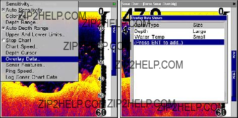
Noise Rejection
See the entry on Advanced Signal Processing in this section.
Overlay Data
On any Page display except Satellite Status, you can "float" or overlay additional GPS or navigation data on the screen with the Overlay Data command. For example, if you left your watch at home, you could dis- play the local time on top of the map. Or, if you wanted to see details about your route and trip, you could show your bearing, course, average speed and trip distance.
The various data available from your unit are divided into categories in the Overlay Data menu. These categories include GPS Data, Naviga- tion, Trip Calculator, Time, Sonar Data and Miscellaneous Data.
You can select items from any of these categories for display, in any combination ??? the category divisions are there only to help you sort through the information.
Overlay Data highlighted on sonar menu (left). Overlay Data Shown menu (right).
To overlay information on your screen:
1.Press MENU|??? to OVERLAY DATA|ENT.
2.If you currently have any overlay data on your screen, it will be listed here. Select (ENTER TO ADD) and press ENT. The data viewer shows information categories with "+" or
Selecting the category name and pressing ENT will show the category's contents, so you can choose items within it. An expanded category (one with a
79

Data Viewer menu (left). Sonar Data category expanded (right).
3.Expand any categories that might contain data you want to display. Then press ??? or ??? to select a data option.
4.With the data option highlighted, press ENT to check it (turn on) and uncheck it (turn off). As you turn it on, the data will appear on top of the screen. Every Page display has a maximum number of items you can show using the Overlay Data command.
5.After the desired changes are made, press EXIT|EXIT to return to the page display.
Steering arrow
Map Page showing boat cruising Puget Sound, Washington (left) with Overlay Data turned on. This example shows Depth, Ground Speed and the Steering Arrow. Note that the Steering Arrow always points directly to the destination you are navigating toward. In this case, the boater is headed on a northwesterly course of 275??. Since the helms- man is on course, the Steering Arrow is pointing straight ahead. If the boat veered off course, the arrow would show which direction to steer to get back on course. Sonar Page with Overlay Data turned on (right), showing Depth, Ground Speed and the Track the boat is following.
80
To remove overlaid data:
1.While on the Page that shows the item or items you want to remove, press MENU|??? to OVERLAY DATA|ENT.
2.You'll see a list of the overlay data currently displayed. Select the item you want to remove from your display and press ENT|ENT to re- move the data. To remove another item, select the item and press
ENT|ENT.
3. When you have finished removing all the items you want from the screen, press EXIT to return to the page display.
NOTE
You can also remove data directly from the Data Viewer menu by un- checking the data option you would like to remove.
Overlay Data Shown with Water Temp selected (left). Remove button highlighted (center). Water Temp has been removed from Overlay Data Shown menu (right).
To move overlaid data:
You may find it useful to rearrange data that is floating in your display window.
1.From one of the Map Pages, press MENU|??? to OVERLAY DATA|ENT.
2.You'll see a list of the overlay data currently displayed. Select the item you want to move and press ENT|??? to MOVE|ENT.
3.The data begins to flash on your screen. Use any combination of ???, ???, ??? and ??? to move the data to a new location on the screen.
4.When satisfied, press EXIT|EXIT.
NOTE:
The Customize command and the Overlay Data command both use the same information categories. The difference between the two commands is that Customize changes only the data boxes on a
81
screen, and Overlay Data changes only the information floating on the screen without a box. See Customize Page Displays, on page 90, for information on customizing data boxes.
To change displayed data font size:
1.From the Map or Sonar page, press MENU|??? to OVERLAY DATA|ENT.
2.Press ??? or ??? to select Data Type, then use ??? ??? to scroll through the five overlay options: Off, Small, Medium, Large and Enormous.
3.Select the desired setting. The selected data type will be displayed in the new size. To change the font size for another Data Type, repeat Steps 2 and 3. Press EXIT to return to the sonar display.
NOTE:
Some data types can be displayed in only one font size. If that is the case, the Data Size box will not be displayed for that data type.
Ping Speed & HyperScroll???
Ping Speed controls the rate at which the transmitter and transducer broadcast sonar sound waves ??? pings ??? into the water. The unit has a default ping speed of 50 percent. At normal boating speeds, this auto- matically provides enough return echoes to refresh the screen and scroll the chart at maximum chart speed.
However, when you are running at high speeds, or just want the fastest possible screen update, you may want to use the HyperScroll??? feature. When you change the Ping Speed to any setting greater than 50 per- cent, the unit automatically enters HyperScroll mode.
These faster ping rates allow you to maintain a
When using HyperScroll, you may also need to manually decrease the sensitivity for optimum performance. Depending on water depth and other conditions, HyperScroll may cause a second bottom echo to return to the transducer during the next ping cycle, or sounding. This can result in a large amount of clutter appearing on the screen. If this occurs, just decrease the sensitivity to a level that eliminates the clutter. When you turn HyperScroll off, you can return to your original sensitivity level.
82
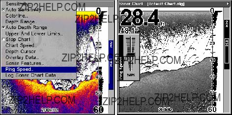
Sonar Menu with Ping Speed selected (left).
Ping Speed Control Bar set to its default setting (right).
To change Ping Speed:
1.From the Sonar Page, press MENU|??? to PING SPEED|ENT.
2.The Ping Speed Control Bar appears. Press ??? to increase ping speed; press ??? to decrease speed. When it's set at the desired level, press EXIT.
To adjust Sensitivity:
1.From the Sonar Page, press MENU|ENT.
2.The Sensitivity Control Bar appears. Press ??? to decrease sensitivity; press ??? to increase sensitivity. When it's set at the desired level, press EXIT. (When you reach the maximum or minimum limit, a tone sounds.)
To turn off HyperScroll:
1.From the Sonar Page, press MENU|??? to PING SPEED|ENT.
2.The Ping Speed Control Bar appears. Press ??? to decrease ping speed to 50 percent. When it's set at the desired level, press EXIT.
When you boost ping speed and switch into HyperScroll, the width of the FasTrack bar graph display doubles in width at the right side of the screen. This allows you to better see the virtually instantaneous sonar returns, just as you would on a flasher sonar unit. For more informa- tion on FasTrack, see its entry in this section.
Reset Options
This command is used to reset all features, options and settings to their original factory defaults. This is useful when you have changed several settings and want to return the unit to basic automatic operation.
1.Press MENU|MENU|??? to SYSTEM SETUP|ENT|??? to RESET OPTIONS|ENT.
2.Press ??? to YES|ENT.
83
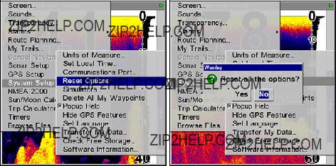
3. All the menus are cleared and the unit reverts to the Map Page at the 4000 mile zoom range, just as if you had turned it on for the first time. All options have been returned to the factory settings.
System Setup menu with Reset Options selected (left). The Reset Op- tions dialog box, with "Yes" selected (right).
NOTE:
Reset Options does not erase any waypoints, routes, plot trails, or sonar logs.
Reset Water Distance
The sonar chart's Digital Data display option includes a box that shows distance traveled, called Water Distance. This information is calculated from an optional water speed sensor, not the GPS. The Water Distance window can be reset to zero using the Reset Water Distance command.
Press MENU|MENU|??? to SONAR SETUP|ENT|??? to RESET WATER DIS-
TANCE|ENT. The menus are cleared and the water distance is reset to 0.00.
Set Keel Offset
This unit measures water depth from the face of the transducer. Since the transducer is installed below the water surface, the distance dis- played by the digital depth, chart depth scale, chart cursor or fish sym- bols is not the exact water depth. If the transducer is 1 foot below the surface, and the screen shows the water depth as 30 feet, then the ac- tual depth is 31 feet.
On sailboats or other large vessels with deep drafts, the distance be- tween the transducer installation and the keel or lower engine unit can be several feet. In those cases, an inexact depth reading could result in grounding or striking underwater structure.
84
The Keel Offset feature eliminates the need for the navigator to men- tally calculate how much water is under his keel.
Keel Offset lets you calibrate the digital depth, chart depth scale, chart cursor depth and fish symbol depth displayed on the screen. To calibrate the depth indicators, first measure the distance from the face of the transducer to the lowest part of the boat. In this example, we will use 3.5 feet. This will entered as a negative 3.5 feet, which makes the depth indi- cators perform as if the transducer's lower in the water than it really is.
1.Press MENU|MENU|??? to Sonar Setup ENT. Use ??? to select SET KEEL
OFFSET|ENT.
2.The Keel Offset dialog box appears. Press ??? to change the plus (+) sign to a minus
3.Press ??? to the first number, then press ??? to change the number to 3
4.Press ??? to the second number, then press ??? to change the number to 5, then press EXIT. The depth indicators now accurately show the depth of water beneath the keel.
NOTE:
If knowing the exact depth of water beneath the keel is less impor- tant, you can calibrate the depth indicators so that they show the ac- tual water depth from surface to bottom. To do this, first measure the distance from the face of the transducer up to the surface (the water line on the boat). In this example, we will use 1.5 feet. This will be en- tered as a positive 1.5 feet, which makes the depth indicators perform as if the transducer's higher in the water than it really is.
1. Press MENU|MENU|??? to Sonar Setup ENT. Use ??? to select SET KEEL
OFFSET|ENT.
2.The Keel Offset dialog box appears with a plus (+) sign at the front of the box.
3.Press ??? to the first number, then press ??? to change the number to 1.
4.Press ??? to the second number, them press ??? to change the num- ber to 5, then press EXIT. The depth indicators now accurately show the water depth from surface to bottom.
Sensitivity & Auto Sensitivity
The sensitivity controls the ability of the unit to pick up echoes. Sensi- tivity can be adjusted, because water conditions vary greatly. A low sensitivity level (from zero to 50 percent) excludes much of the bottom information, fish signals, and other target information.
85
High sensitivity levels let you see this detail, but it can also clutter the screen with many undesired signals. Typically, the best sensitivity level shows a good solid bottom signal with Colorline and some surface clutter.
Automatic Sensitivity
The default sensitivity mode is automatic. The unit bases the sensitiv- ity level on water depth and conditions. When the unit is in the auto- matic mode, sensitivity is automatically adjusted to keep a solid bottom signal displayed, plus a little more power. This gives it the capability to show fish and other detail.
However, situations occur when it becomes necessary to increase or decrease the sensitivity. This typically happens when you wish to see more detail, so an increase in sensitivity is indicated. Or, wave action and boat wakes can create enough tiny air bubbles to clutter much of the water column. In that case, a decrease in sensitivity is indicated to reduce some of the clutter.
The control bar used to adjust sensitivity up or down is the same whether the unit is in the automatic or manual mode. In automatic you can adjust sensitivity up to 100 percent but the unit will limit your minimum setting. In auto, the unit will continue to make small ad- justments, allowing for the setting you selected.
In manual mode, you have complete control over sensitivity, with the ability to set it anywhere from zero to 100 percent. Once you select a level in manual, the unit will continue to use that exact sensitivity set- ting until you change it or revert to auto mode.
To adjust sensitivity in auto mode:
1.Press MENU|ENT.
2.The Sensitivity Control Bar appears. Press ??? to decrease sensitivity; press ??? to increase sensitivity. When it's set at the desired level, press EXIT. (When you reach the maximum or minimum limit, a tone sounds.)
86
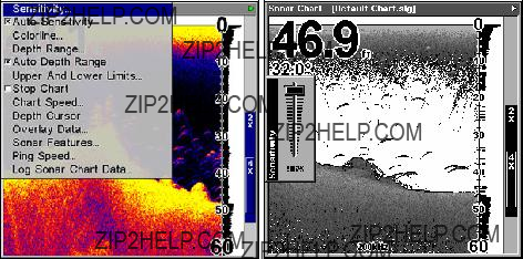
Sonar Menu with Sensitivity selected (left). The Sensitivity Control Bar (right).
To adjust sensitivity in manual mode:
1.First, turn off Auto Sensitivity: from the Sonar Page, press MENU|???
to AUTO SENSITIVITY|ENT.
2.Press ??? to SENSITIVITY|ENT and the Sensitivity Control Bar appears. Press ??? or ??? to pick a different sensitivity setting. When it's set at the desired level, press EXIT.
To turn Auto Sensitivity back on:
From the Sonar Page, press MENU|??? to AUTO SENSITIVITY|ENT|EXIT.
NOTE:
To return to the original factory setting for Auto Sensitivity, see the entry in this section on Reset Options. If sensitivity is in manual mode, the Reset Options command will switch back to Auto and re- set the factory setting at the same time.
Tip:
For quicker sensitivity adjustments, try leaving the Sensitivity Control Bar on the screen as the chart scrolls. You can see the changes on the screen as you press the up or down arrows. This is handy when there's a lot of clutter in the water, and you are match- ing the sensitivity to rapidly changing water conditions.
Sonar Chart Mode
The default color scheme for the sonar chart is the white background, but we offer other variations to suit your viewing preferences. The chart can be displayed in grayscale, reverse grayscale, blue back- ground, white background, nightview, iceview, or bottom color tracking.
87
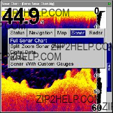
To change the chart mode color scheme:+
1.From the Sonar Page, press MENU|??? to SONAR FEATURES|ENT.
2.Press ??? to SONAR CHART MODE|ENT.
3.Press ??? or ??? to Mode Name|ENT.
4.Press EXIT|EXIT to return to the Sonar Page.
Sonar Page & Sonar Chart Display Options
The Pages Menu offers five chart display options for
PAGES|??? or??? to SONAR|??? to Option Name|EXIT.
Pages Menu showing sonar chart display options.
Full Sonar Chart
This is the default mode used when the unit is turned on for the first time or when it's reset to the factory defaults.
The bottom signal scrolls across the screen from right to left. Depth scales on the right side of the screen aid in determining the depth of targets. The line at the top of the screen represents the surface. The bottom depth and surface temperature (if equipped with a temperature sensor or a transducer with a temp sensor built in) show at the top left corner of the screen.
The FasTrack??? display shows just to the right of the scale. This changes all echoes into short horizontal bars, replicating a flasher so- nar. The zoom bar on the far right shows the area that's zoomed when the zoom is in use. (See the Zoom section for more information.)
88

Full Sonar Chart. The Overlay Data (depth and water temperature) are both set to the small text size.
Split Zoom Sonar Chart
A split chart shows the underwater world from the surface to the bot- tom on the right side of the screen. The left side shows an enlarged ver- sion of the right side. The zoom range shows in the bottom left corner.
Split Zoom Sonar Chart. The left window is zoomed 2X in the first im- age (left). The left window is zoomed 4X in the second image (right).
Split Frequency Sonar Chart
This page shows sonar data from the 50 kHz transducer on the left side of the screen and data from the 200 kHz transducer on the right side. All other functions and features are the same as the Full Chart page.
You can adjust the sensitivity in each window.
To adjust sensitivity in auto mode:
1.Press MENU|ENT.
2.The unit asks which window (50kHz or 200kHz) you would like to adjust. Press ??? or??? to select the one you want | ENT.
89
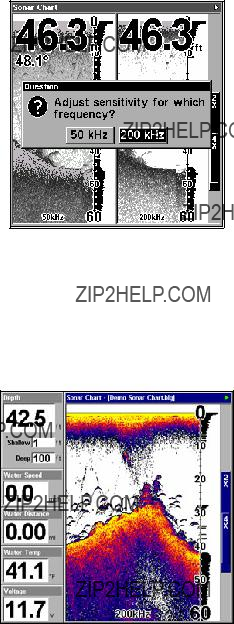
3. The Sensitivity Control Bar appears. Press ??? to decrease sensitivity; press ??? to increase sensitivity. When it's set at the desired level, press EXIT. (When you reach the maximum or minimum limit, a tone sounds.)
The Split Frequency Sonar Chart page allows you to adjust sensitivity separately for each window.
Digital Data/Chart
This mode shows the chart on the right side of the screen. The left side has five digital data boxes containing: Water Depth; Water Speed (from an op- tional speed sensor); Water Distance (distance traveled or log, it also re- quires a speed sensor); Surface Water Temperature and Voltage.
Digital Data/Chart
Customize Page Displays
Every Page display option except Full Map (on the Map Page) has cus- tomizable data boxes to provide constant
The data available from your unit is divided into categories in the Data Viewer menu. These categories include GPS Data, Navigation, Trip
90
Calculator, Time, Sonar Data and Miscellaneous Data. You can select items from any of these categories for display in any data box ??? the category divisions are only there to help you sort through the informa- tion.
To change the information displayed in a data box:
1.On the Page display you wish to change, press MENU|??? to CUSTOM- IZE|ENT. A data box name flashes, indicating it is selected.
2.Press ENT to change the box or hit ???, ???, ??? or ??? to select another box, then press ENT. You'll see a list of categories with "+" or
Customize Menu, with "GPS Data" and "Navigation" categories expanded.
3.Selecting the category name and pressing ENT will show the cate- gory's contents, so you can choose items within it. An expanded cate- gory (one with a
4.Expand any categories that might contain data you want to display. Then press ??? ??? to select a different data option.
5.With the new option highlighted, press ENT to switch the contents of the box to the new data type, then press EXIT.
6.You can now select another box to change. When you are finished with the settings, press EXIT again to end the Customize command, and the box name stops flashing.
A Page display can show a limited number of data boxes. You can not turn them off or add more data boxes.
91
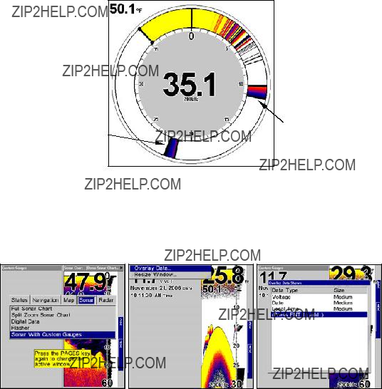
Flasher
The Flasher sonar page option represents a flasher style sonar com- bined with a scrolling chart. A circular dial shows all returning echoes at a high screen refresh rate. It uses the Colorline feature to show weaker targets as lighter colors. The bottom depth is also shown as a black bar across the outer circle. You can adjust the size of the chart and the flasher windows by using the Resize Window command, which is described in Sec. 6.
 Surface clutter
Bottom signal
Flasher page.
Sonar with Custom Gauges
The Sonar with Custom Gauges page has a split screen with sonar on the right side, digital gauge information on the left side. The two win- dows can be resized to make one side bigger than the other or may be set up to split the screen evenly.
Sonar with Custom Gauges selected on the Pages menu (left). To change custom gauge information, access overlay data on the Custom Gauges menu (center). Overlay Data shown menu (right).
92
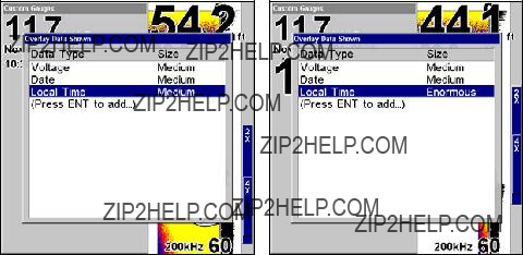
To customize digital gauge display:
1.Press PAGES, highlight SONAR WITH CUSTOM GAUGES and press ENT.
2.Press MENU, select OVERLAY DATA and press ENT. The Overlay Data shown menu will appear.
3.Highlight (PRESS ENT TO ADD???) and press ENT to open the Data Viewer menu with three expandable data categories: Time, Sonar Data and Sensor Data.
4.Highlight the desired data category and press ENT, which will ex- pand the list, revealing several subcategories with checkboxes next to them.
5.Select the desired subcategory and press ENT, which will place a checkmark in the checkbox, showing the selected data is set for display.
6.If you want to display other data types, repeat Steps 4 and 5. Press EXIT repeatedly to get back to the Sonar with Custom Gauges page. The data you selected will now be displayed in the gray area on the left side of the screen.
To change Overlay data size:
1.From the Sonar with Custom Gauges page, press MENU SELECT OVER- LAY DATA and press ENT. The Overlay Data Shown menu will appear.
2.Highlight the Data Type you want to resize, then use ??? ??? to set the data to the desired size to one of four options: Off, Small, Medium, Large and Enormous.
Local Time is set to medium size (left). The size of Local Time data has been changed to Enormous (right).
3. To change the size of another Data Type, repeat the steps above. To return to the Sonar with Custom Gauges display, press EXIT.
93
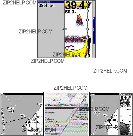
To resize Sonar and Custom Gauge windows:
1.From the Sonar with Custom Gauges page, press MENU, select RESIZE WINDOW and press ENT.
2.Use ??? ??? to increase or decrease the size of each window. Press EXIT.
When the Resize Windows command is active, two arrows will appear between the two windows.
Map with Sonar Split Screen
There is a page mode that splits the screen in half, with the map on the left and the sonar on the right. This screen option can be found on the Pages Menu under the Map Page category.
Full Map page (left). Pages Menu with the Map option list (center). The Map with Sonar screen (right).
When the split screen is activated, you need to specify which side of the display is the active menu. To do this, press PAGES|PAGES. The window with the blue title bar at the top of the screen is the active window. To switch back, just press PAGES|PAGES again.
94

Sonar Simulator
This unit has a
To use the simulator:
1. From the Sonar Page, press MENU|MENU|??? to SYSTEM SETUP|ENT|???
to SIMULATORS|ENT.
System Setup menu with Simulators selected (left). Sonar Simulator page with Sonar Simulator On highlighted (right). The checkbox next Sonar Simulator On is checked (turned on).
NOTE:
With Simulate Position checked, the simulator will automatically run the GPS simulator (if GPS data was recorded with the sonar log).
2.Press ??? to highlight SONAR SIMULATOR tab. To turn on the simulator, highlight SONAR SIMULATOR ON and press ENT, which will place an X in the checkbox. Repeat these steps to turn off the simulator.
3.Press EXIT repeatedly to return to the main display.
95
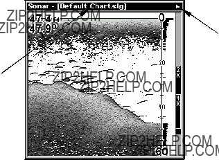
"Play" symbol flashing
Title bar with chart file name
Sonar Page, playing a recorded sonar chart in Sonar Simulator mode.
Tip:
The Sonar Simulator can use sonar charts that you or a friend have recorded (logged) on a MMC card. (To see how, read the entry in this section on Log Sonar Chart Data.) To play back your own sonar chart, make sure the MMC containing the chart is installed, then:
1. Press MENU|MENU|??? to SONAR SETUP|ENT|??? to SONAR SIMULA- TOR|ENT.
2.Press ??? to CHART USED|ENT.
3.Press ??? or ??? to select chart name|ENT|??? to SONAR SIMULATOR
ON|ENT|EXIT.
While you're in the Sonar Simulator menu, don't forget to check Simulate Position if you want to run the sonar and GPS simulators simultaneously. As you review sonar logs, you can create waypoints to mark the sites you want to revisit.
While the simulator is running, you can switch from one chart log to another by opening the Sonar Simulator menu and using the in- structions in step 2 to select a different chart.
Tip:
There's more than one way to play a recorded sonar chart. You can also turn on the simulator from the MMC files list. Here's how:
1.Press MENU|MENU|??? to BROWSE MMC FILES|ENT|ENT.
2.Press ??? ??? to file name|ENT|??? to PLAY|ENT|EXIT.
96
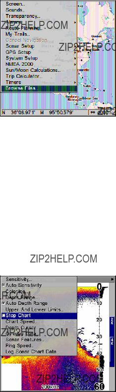
Select Browse MMC Files from the Main Menu.
NOTE:
If you turn on your unit before attaching a transducer, it may enter a demo mode. The words "demo mode" flash on the bottom of the screen and a sonar chart plays much like the simulator. Unlike the simulator, the demo mode is for demonstration only, and will auto- matically stop as soon as you turn on the unit with a transducer at- tached. The simulator will continue to function normally.
Stop Chart
If you are running multiple units on a boat or using this unit in a car, there are times when you may want to turn off the sonar. This com- mand turns off the sonar and stops the chart from scrolling. Sonar re- starts automatically each time you turn on your unit.
1. From a Sonar Page, press MENU|??? to STOP CHART|ENT|EXIT. Repeat this step to restart the chart.
Sonar Menu with Stop Chart command selected. The box is unchecked, indicating that the chart is scrolling across the screen.
97

Surface Clarity
The markings extending downward from the zero line on the chart are called "surface clutter." These markings are caused by wave action, boat wakes, temperature inversion and more.
The surface clarity control reduces or eliminates surface clutter signals from the display. It does this by changing the sensitivity of the receiver, decreasing it near the surface and gradually increasing it as the depth increases.
There are three levels of surface clarity available: low, medium, or high. It can also be turned off. The default level is off.
Sonar Features menu with Surface Clarity selected.
To adjust the Surface Clarity level:
1.From the Sonar Page, press MENU|??? to SONAR FEATURES|ENT.
2.Press ??? to SURFACE CLARITY|ENT.
3.Press ??? or ??? to select clarity level|EXIT repeatedly.
98

Surface clutter
In the illustration at left, Surface Clarity is turned off. The right view shows Surface Clarity set at High.
Transparency
Use the transparency menu to adjust the transparency of menu win- dows. A high transparency allows you to continue monitoring the screen's display while adjusting feature settings, though the text of the menus may fade until it is unreadable. A low transparency will usually make menu text easier to read, at the cost of watching your display.
Experiment with this feature until you find the right level of transpar- ency for your eyes.
Main Menu with Transparency command selected. Transparency con- trol bar (right).
To adjust Menu Transparency level:
Press MENU|MENU|??? to TRANSPARENCY|ENT. The TRANSPARENCY slider bar appears. Press ??? or ??? to move the bar. The lower end of the scale makes the menus opaque; the upper end is maximum transparency.
99
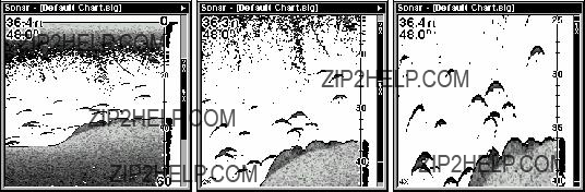
Upper and Lower Limits
See the entry in this section for Depth Range - Upper and Lower Lim- its.
Zoom & Zoom Bar
"Zooming" the display is a common, fast and easy method used to en- large small detail, fish signals and the bottom with its associated struc- ture. This unit lets you zoom the display quickly and easily by pressing the Zoom In key, ZIN.
Pressing ZIN once doubles the size (2X) of all echoes on the screen. Pressing it again quadruples the size of the echoes (4X). The zoom bar on the far right side of the screen shows which echoes will be displayed on the screen when the ZIN key is pressed.
For example, pressing the ZIN key once will enable a 2X zoom which will show all echoes that are between the top and bottom of the 2X zoom bar. Pressing the key again will give a 4X zoom and only the ech- oes between the top and bottom of the 4X bar will show on the screen.
Press the Zoom Out key, ZOUT, to return the display to the normal mode.
Sonar Page with a normal view (left). The second image (center) is showing the same view zoomed 2X. The third image (right) is showing the same view zoomed 4X.
Zoom Pan
Your unit has the handy ability to quickly zoom in on any portion of the water column with just the touch of an arrow key. The Zoom Pan feature lets you rapidly move the zoomed area up and down to different depths. By "pointing" your zoom at different portions of the chart as it scrolls, you can get a good,
To use Zoom Pan, switch to a manual depth Range setting (see page 71) and turn on 2X or 4X Zoom. Then, simply press ??? ??? to pan up and down the water column.
100
Section 5: Sonar Troubleshooting
If your unit is not working, or if you need technical help, please use the following troubleshooting section before contacting the customer ser- vice department. It may save you the trouble of returning your unit for repair. For contact information, refer to the last page, just inside the back cover of this manual.
Unit won't turn on
1.Check the power cable's connection at the unit. Also check the wiring.
2.Make sure the power cable is wired properly. The red wire connects to the positive battery terminal, black to negative or ground.
3.Check the fuse.
4.Measure the battery voltage at the unit's power connector. It should be at least 10 volts. If it isn't, the wiring to the unit is defective, the battery terminals or wiring on the terminals are corroded, or the bat- tery needs charging.
Unit freezes, locks up, or operates erratically
1.Electrical noise from the boat's motor, trolling motor, or an accessory may be interfering with the sonar unit. Rerouting the power and trans- ducer cables away from other electrical wiring on the boat may help. Route the sonar unit's power cable directly to the battery instead of through a fuse block or ignition switch
2.Inspect the transducer cable for breaks, cuts, or pinched wires.
3.Check the transducer and power connector. Make sure it's securely plugged in to the unit.
Weak bottom echo, digital readings erratic, or no fish signals
1.Make sure the transducer is pointing straight down. Clean the face of the transducer. Oil, dirt and fuel can cause a film to form on the trans- ducer, reducing its effectiveness. If the transducer is mounted inside the hull, be sure it is shooting through only one layer of fiberglass and that it is securely bonded to the hull. When attaching a transducer to the inside of a hull, ONLY use the epoxy available from LEI (order information is inside the back cover). Do NOT use RTV silicone rubber adhesive or any other type of epoxy. The LEI epoxy is specially formulated so that it will cure properly for
2.Electrical noise from the boat's motor can interfere with the sonar. This causes the sonar to automatically increase its discrimination or noise rejection feature. This can cause the unit to eliminate weaker sig- nals such as fish or even structure from the display.
101
3.The water may be deeper than the sonar's ability to find the bottom. If the sonar can't find the bottom signal while it's in the automatic mode, the digital sonar display will flash continuously. It may change the range to limits far greater than the water you are in. If this hap- pens, place the unit in the manual mode, then change the range to a realistic one, (for example,
4.Check the battery voltage. If the voltage drops, the unit's transmitter power also drops, reducing its ability to find the bottom or targets.
Bottom echo disappears at high speeds or erratic digital read- ing or weak bottom echo while boat is moving
1.The transducer may be in turbulent water. It must be mounted in a smooth flow of water in order for the sonar to work at all boat speeds. Air bubbles in the water disrupt the sonar signals, interfering with its ability to find the bottom or other targets. The technical term for this is cavita- tion.
2.Electrical noise from the boat's motor can interfere with the sonar. This causes the sonar to automatically increase its discrimination or noise rejection feature. This can cause the unit to eliminate weaker sig- nals such as fish or even structure from the display. Try using resistor spark plugs or routing the sonar unit's power and transducer cables away from other electrical wiring on the boat.
No fish arches when the Fish I.D. feature is off
1.Make sure the transducer is pointing straight down. This is the most common problem if a partial arch is displayed.
2.The sensitivity may not be high enough. In order for the unit to dis- play a fish arch, it has to be able to receive the fish's echo from the time it enters the cone until it leaves. If the sensitivity is not high enough, the unit shows the fish only when it is in the center of the cone.
3.Use the Zoom feature. It is much easier to display fish arches when zoomed in on a small range of water than a large one. For example, you will have much better luck seeing fish arches with a 30 to 60 foot range than a 0 to 60 foot range. This enlarges the targets, allowing the dis- play to show much more detail.
4.The boat must be moving at a slow trolling speed to see fish arches. If the boat is motionless, fish stay in the cone, showing on the screen as straight horizontal lines.
NOISE
A major cause of sonar problems is electrical noise. This usually ap- pears on the sonar's display as random patterns of dots or lines.
102
In severe cases, it can completely cover the screen with black dots, or cause the unit to operate erratically, or not at all.
To eliminate or minimize the effects of electrical noise, first try to de- termine the cause. With the boat at rest in the water, the first thing you should do is turn all electrical equipment on the boat off. Make sure the engine is also off. Turn your sonar on, then turn off Noise Re- ject [also known as the ASP feature (Advanced Signal Processing)]. Sensitivity should be set at
If you find noise interference from an electrical instrument, trolling motor, pump, or radio, try to isolate the problem. You can usually re- route the sonar unit's power cable and transducer cable away from the wiring that is causing the interference. VHF radio antenna cables radi- ate noise when transmitting, so be sure to keep the sonar's wires away from it. You may need to route the sonar unit's power cable directly to the battery to isolate it from other wiring on the boat.
If no noise displays on the sonar unit from electrical equipment, then make sure everything except the sonar unit is turned off, then start the engine. Increase the RPM with the gearshift in neutral. If noise ap- pears on the display, the problem could be one of three things; spark plugs, alternator, or tachometer wiring. Try using resistor spark plugs, alternator filters, or routing the sonar unit's power cable away from engine wiring. Again, routing the power cable directly to the battery helps eliminate noise problems. Make sure to use the
When no noise appears on the sonar unit after all of the above tests, then the noise source is probably cavitation. Many novices or persons with limited experience make hasty sonar installations which function perfectly in shallow water, or when the boat is at rest. In nearly all cases, the cause of the malfunction will be the location and/or angle of the transducer. The face of the transducer must be placed in a location that has a smooth flow of water at all boat speeds. Read your trans- ducer owner's manual or the Installation instructions (Sec. 2) in this manual for the best mounting position.
103
Notes
104

Section 6: Basic GPS Operations
This section addresses the unit's most basic GPS operations. Before you turn on the unit and find where you are, it's a good idea to learn about the different keys, the four Page screens and how they all work to- gether. BUT, if you just can't wait to get outside, turn to the
Quick Reference on page 121.
Keyboard
MMC slot access door 
1.PWR/LIGHT (Power & Light) ??? The PWR key turns the unit on and off and activates the backlight.
2.PAGES ??? Pressing this and the ??? ??? arrow keys (4) switches the unit between the four different page screens. (Satellite Status Page, Navigation Page, Map Page and Sonar Page.) Each page represents one of the unit's major operation modes.
105
3.MENU ??? Press this key to show the menus and submenus, which allow you to select a command or adjust a feature. This also accesses search functions for streets, intersections, addresses and highway exits.
4.ARROW KEYS ??? These keys are used to navigate through the menus, make menu selections, move the map cursor and sonar chart cursor and enter data.
5.ENT/ICONS (Enter & Icons) ??? This key allows you to save data, ac- cept values or execute menu commands. It is also used to create event marker icons.
6.EXIT ??? The Exit key lets you return to the previous screen, clear data or close a menu.
7.WPT ??? (Waypoint) The Waypoint key is used to save and recall way- points, search for waypoints and access the waypoint list. It also launches the
8.ZOUT ??? (Zoom Out) ??? This key lets you zoom the screen out. On the Sonar Page, this key returns you to a full sonar chart display, showing the entire water column from surface to bottom. On the Map Page, this lets you see a larger geographic area on the map. Less detail is seen as you zoom out.
9.ZIN ??? (Zoom In) ??? This key lets you zoom the screen in. On the Sonar Page, this key enlarges fish signals and bottom detail. On the Map Page, zooming in lets you see greater detail in a smaller geographic area on the map.
Power/lights on and off
To turn on the unit, press PWR. As the unit powers up, the Map Page is displayed first. (To switch to another page, press PAGES|??? or ??? to
Page Name|EXIT.)
To turn on the backlight, press PWR again. The unit has three back- light levels to select from. Repeatedly pressing PWR will cycle through the backlight settings and turn off the backlight.
Turn off the unit by pressing and holding the PWR key for 3 seconds.
Main Menu
The unit has a Main Menu, which contains some function commands and some setup option commands. The tutorial lessons in this section will deal only with functions, the basic commands that make the unit do something. The GPS will work fine for these lessons right out of the box with the factory default settings. But, if you want to learn about the vari- ous options, see Sec. 8, System Setup and GPS Setup Options.
106
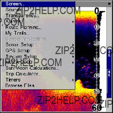
You can access the Main Menu from any of the four Page screens by pressing MENU|MENU. To clear the menu screen and return to the page display, press EXIT.
Main Menu.
The Main Menu commands and their functions are:
Screen: changes the contrast or brightness of the display screen.
Sounds: enables or disables the sounds for key strokes and alarms and sets the alarm style.
Transparency: adjusts the level of transparency for menus.
Alarms: turns GPS or sonar alarms on or off and changes alarm thresholds.
Route Planning: used to plan, view or navigate a route.
My Trails: shows, hides, creates and deletes plot trails. Also used to navigate or backtrack a trail.
Cancel Navigation: turns off the various navigation commands. Used to stop navigating after you have reached your destination waypoint, Point of Interest or map cursor location; or after you reach the end of a route or trail.
Sonar Setup: sets various sonar options.
GPS Setup: sets various GPS receiver options.
System Setup: sets general configuration options.
NMEA 2000: provides access to all NMEA 2000 network setup options, including the configuration of devices on the network. For more infor- mation, see Section 10: NMEA 2000 Menu.
Sun/Moon Calculations: finds the rising and setting time of the sun and the moon.
Trip Calculator: shows trip status and statistics.
107
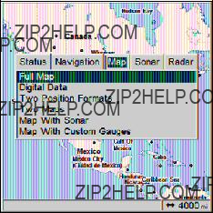
Timers: controls the up timer, down timer and alarm clock settings.
Browse MMC Files: this allows you to view the installed MMC card and the files it contains.
Pages
The unit has four Page displays that represent the five major operating modes. They are the Satellite Status Page, the Navigation Page, Map Page and the Sonar Page. They are accessed by pressing the PAGES key, then using ??? or ??? to select a Page. (Clear the Pages menu by pressing
EXIT.)
Pages Menu showing Map page options.
Sonar Page
The Sonar Page displays the sonar chart, a view of the water column from the surface to the bottom. The chart scrolls across the screen from right to left, displaying signal echoes that represent fish, structure and the bottom. The Sonar Page is discussed in detail in Sec. 3.
Satellite Status Page
The Satellite Status Page provides detailed information on the status of the unit's satellite
No matter what Page you are on, a flashing current position indica- tor/question mark symbol and flashing GPS data displays indicate that satellite lock has been lost and there is no position confirmed. The Sat- ellite Status Page shows you the quality and accuracy of the current satellite
WARNING:
Do not begin navigating with this unit until the numbers have stopped flashing!
108
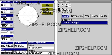
Satellite Status Page (left). Custom Gauges (right).
This screen will show a graphical view of the satellites that are in view. Each satellite is shown on the circular chart relative to your position. The point in the center of the chart is directly overhead. The small inner ring represents 45?? above the horizon and the large ring represents the horizon. North is at the top of the screen. You can use this to see which satellites are obstructed by obstacles in your immediate area if the unit is facing north.
The GPS receiver will track satellites that are in bold type. The re- ceiver hasn't locked onto a satellite if the number is grayed out, there- fore it isn't being used to calculate your position.
Beneath the circular graph will be bar graphs, one for each satellite in view. Since the unit has twelve channels, it can dedicate one channel per visible satellite. The taller the bar on the graph, the better the unit is receiving the signals from the satellite.
You can set up custom digital gauges through the Satellite Status page menu. The Custom Gauges feature allows you to monitor a wide vari- ety of data from one page.
To set up Custom Gauge page:
1. Select the SATELLITE STATUS page from the Pages menu, highlight CUS- TOM GAUGES and press ENT.
2.Press MENU. OVERLAY DATA will highlighted, so press ENT. The Overlay Data shown menu will appear.
3.Highlight (PRESS ENT TO ADD???) and press ENT to open the Data Viewer menu with five expandable data categories: GPS Data, Navigation, Trip Calculator, Time and Sensor Data.
4.Highlight the desired data category and press ENT, which will ex- pand the list, revealing several subcategories with checkboxes next to them.
109
5.Select the desired subcategory and press ENT, which will place a checkmark in the checkbox, showing the selected data is set for display.
6.If you want to display other data types, repeat Steps 4 and 5. Press EXIT repeatedly to get back to the Custom Gauges page. The data you selected will now be displayed on the screen.
To change Overlay data size:
1.From the Custom Gauges page, press MENU SELECT OVERLAY DATA and press ENT. The Overlay Data Shown menu will appear.
2.Highlight the Data Type you want to resize, then use ??? ??? to set the data to the desired size to one of four options: Off, Small, Medium, Large and Enormous.
3.To change the size of another Data Type, repeat the steps above. To return to the Sonar with Custom Gauges display, press EXIT.
NOTE:
One of the data display options for the Satellite Status page is "Po- sition Error" (horizontal position error), which can appear in one of the page's data boxes. If you turn on Position Error, it will show you the expected error from a benchmark location. In other words, if the Position Error box shows 50 feet, then the position shown by the unit is estimated to be within 50 feet of the actual location.
This also gives you an indicator of the fix quality the unit currently has. The smaller the position error number, the better (and more ac- curate) the fix is. If the position error flashes dashes, then the unit hasn't locked onto the satellites, and the number shown isn't valid. (For details, see the Customize Page Displays entry in Sec. 8.)
The Satellite Status Page has its own menu, which is used for setting various options. (Options and setup are discussed in Sec. 8). To access the Satellite Status Page Menu, from the Status Page, press MENU.
Navigation Page
This screen has a compass rose that not only shows your direction of travel, but also the direction to a recalled waypoint. The page has two options, navigation with digital data and navigation with sonar. To get to the Navigation Page: Press PAGES|??? or ??? to NAVIGATION. Press ??? or ???|EXIT to select one of the two menu items.
The navigation screen looks like the one below when you're not navi- gating to a waypoint or following a route or trail. Your position is shown by an arrow in the center of the screen. Your trail history, or path you've just taken, is depicted by the line extending from the ar- row. The arrow pointing down at the top of the compass rose indicates the current track (direction of travel) you are taking.
110
Track or compass heading indicator, showing direction of travel
Trail line
The Navigation with Digital Data Page recording a trail, while travel- ing southwest. Page looks like this when the unit is not navigating to a waypoint, following a route, or backtracking a trail.
Navigation with Sonar page.
When navigating to a waypoint, your ground speed, track, distance, bearing to the waypoint and course are all displayed.
NOTE:
Remember, when the Speed, Track and Position information dis- plays are flashing, satellite lock has not been achieved and no posi- tion fix has been determined. A question mark will also flash on the present position arrow in the center of the compass rose.
Speed (ground speed) is the velocity you are making over the ground. (If you wish, you can customize the Speed data box to display Closing Speed instead. Closing Speed is also known as velocity made good.
111

It's the speed that you're making toward the waypoint. For instruc- tions, see the Customize Page Displays entry in Sec. 8.)
Track is the heading, or the current direction you are actually travel- ing. Bearing is the direction of a
The Off Course window shows the current cross track error. This shows the distance you are
Navigation Page.
The cross track error range is shown on the compass rose as a wide, white, corridor enclosing the course line. The outer edges of this white corridor represent lines that show the current cross track error range. The default for the cross track error range is 0.20 miles.
For example, if the present position symbol touches the right cross track error line, then you are 0.20 miles to the right of the desired course. You need to steer left to return to the desired course. You can use the ZIN or ZOUT keys to change the cross track error range.
112
A circular symbol showing your destination (waypoint) appears on the screen as you approach the waypoint, as shown on the screen in the preceding figure.
Travel Time is the time that it will take to reach your destination at your present closing speed. (You can also customize the time data box to show Arrival Time instead. Arrival Time is the local time it will be when you arrive at the destination, based upon your present closing speed and track.)
In the preceding example, the driver is headed west (a 265?? track) to- ward a waypoint 265?? (bearing) away. The cross track error range (white corridor) is 0.20 miles either side of the course. The driver is headed toward trail waypoint 4, which is 0.3 miles away. The vehicle is right on course. Traveling at a speed of 8 mph, the driver will arrive at the waypoint in 2 minutes, 17 seconds.
The Navigation Page has its own menu, which is used for some ad- vanced functions and for setting various options. (Options and setup are discussed in Sec. 8). To access the Navigation Page Menu, from the Navigation Page, press MENU.
Map Page
The Map Page screens show your course and track from a
Map Page is the default screen that appears when you turn on the unit. To get to the Map Page from another page: Press PAGES|??? or ??? to MAP|EXIT. When the Map Page is displayed, a screen similar to the fol- lowing figures appears.
The arrow in the center of the screen is your present position. It points in the direction you're traveling. The solid line extending from the back of the arrow is your plot trail, or path you've taken.
The map zoom range is the distance across the screen. This number shows in the lower right corner of the screen. In the first of the follow- ing example figures, the range is 4,000 miles from the left edge of the map to the right edge of the map.
The Zoom In and Zoom Out keys zoom the map to enlarge or reduce its coverage area and the amount of mapping detail shown. There are 39 available map zoom ranges, from 0.02 miles to 4,000 miles.
113
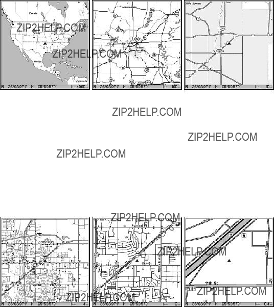
Map Page opening screen (left). Set to
If you're using only the
Map Pages with
At a
Background map vs. MapCreate map content
The background map includes:
114

and some major city streets. Also included are Interstate, U.S. and state highways, large- and
MapCreate custom maps include massive amounts of information not found in the background map. MapCreate contains: the searchable Points of Interest database, all the minor roads and streets, all the landmark features (such as summits, schools, radio towers, etc.); more rivers, streams, smaller lakes and ponds and their names.
What's more important is the large scale map detail that allows your GPS unit to show a higher level of position accuracy. For example, the background map would show you the general outline and approximate shape of a coastline or water body, but the higher detail in MapCreate shows the shoreline completely and accurately (finer detail). Many smaller islands would not be included in the background map, but are in MapCreate.
NOTE:
Available through LEI Extras (look inside back cover for accessory ordering information), FreedomMaps are
Minor
Streets
POI
POIPop-up
Marker
Position,
distance andZoom Range bearing data
When the map is zoomed out far enough, most POIs appear as square dots. As you zoom in closer, the symbols become readable icons. In the 0.2 mile zoom example (right), the cursor has selected the Cupps Caf?? POI, which triggers a
115

Tip:
In some urban areas, businesses are so close to one another that their POI icons crowd each other on the screen. You can reduce screen clutter and make streets and other map features easier to see by simply turning off the display of POIs you're not watching for. (To see how, check the text on Map Detail Category Selection, page 166. It shows how to use the Map Categories Drawn menu to turn individual POI displays off and on.) Even though their display is turned off, you can still search for POIs and their icons will pop- up when your unit finds them for you.
The Map Page has its own menu, which is used for several functions and for setting various options. To access the Map Page Menu, from the Map Page, press MENU.
The Pages Menu also offers several map display options under the Map Page category. To access them, press PAGES|??? ??? to MAP|??? to Op- tion|EXIT.
Digital Data map page (left). Two Position Formats page (right).
In pages that have two major windows (such as two maps) you can tog- gle back and forth between the two windows by pressing PAGES|PAGES. This allows you to change which map your cursor moves on, and which map the menu operates on. The window with the blue title bar is the active window.
116
Pages Menu with Two Map option selected (left). The windows are in a horizontal position. Map Page with two vertical windows (right).
Resize Window is another feature for pages that have two major win- dows. You can change the horizontal size of the windows to suit your viewing preference.
1.From any
2.Four flashing arrows appear along the centerline dividing the two windows. The windows will be in a horizontal position by default, so
press ??? ??? to resize the windows. Or, if you want to realign the windows vertically, use ??? ??? to switch the windows from a horizontal position to a vertical position. After the windows are in a vertical position, press ??? ??? to resize the windows. Press EXIT to clear the menu.
3. To change the window size again or revert to the original display, just follow the steps above. You can also use the Reset Options com- mand to revert to the factory default.
Map with Sonar
The Map with Sonar page evenly splits the screen between the map view and sonar view. The windows may be resized to fit your prefer- ence.
To resize Map with Sonar windows:
1.Press PAGES, highlight MAP, select MAP WITH SONAR and press ENT.
2.Press MENU, highlight RESIZE WINDOWS and press ENT. Two horizontal arrows will appear on the screen.
3.Use ??? ??? to increase or decrease the size of the windows. Press EXIT to return to normal operation.
117

Map with Sonar highlighted on Pages menu (left). Resize Windows se- lected on Map with Sonar menu (center). Dual arrows are shown as windows are resized (right).
Map with Custom Gauges
The Map with Custom Gauges page has a split screen with a map on the right side and digital gauge information on the left side. The two windows can be resized to make one side bigger than the other or may be set up to split the screen evenly.
Map with Custom Gauges highlighted on Pages menu (left). Overlay Data selected on Map with Custom Gauges menu (right).
To customize digital gauge display:
1.Press PAGES, highlight Map, select MAP WITH CUSTOM GAUGES and press
ENT.
2.Press MENU, select OVERLAY DATA and press ENT. The Overlay Data shown menu will appear.
3.Highlight (PRESS ENT TO ADD???) and press ENT to open the Data Viewer menu with five expandable data categories: GPS Data, Navigation, Trip Calculator, Time, Sonar Data and Sensor Data.
118

4.Highlight the desired data category and press ENT, which will ex- pand the list, revealing several subcategories with checkboxes next to them.
5.Select the desired subcategory and press ENT, which will place a checkmark in the checkbox, showing the selected data is set for display.
6.If you want to display other data types, repeat Steps 4 and 5. Press EXIT repeatedly to get back to the Map with Custom Gauges page. The data you selected will now be displayed in the gray area on the left side of the screen.
To change Overlay data size:
1.From the Map with Custom Gauges page, press MENU select OVERLAY DATA and press ENT. The Overlay Data Shown menu will appear.
2.Highlight the Data Type you want to resize, then use ??? ??? to switch the data setting to one of the following four options: Off, Small, Me- dium, Large and Enormous.
3.To change the size of another Data Type, repeat the steps above. To return to the Sonar with Custom Gauges display, press EXIT.
Ground Speed is set to small size (left). The size Ground Speed data has been changed to Large (right).
Radar
When you access the Radar Page, the screen will switch to the radar dis- play. Information on radar installation and radar operation are included in two documents that come packed with Lowrance radar units: Radar and RIM 100 Radar Interface Module Installation Instructions and Radar Operation Instruction Manual. Refer to these documents for information on your radar unit.
119

Radar Page (left) with Radar menu display (right).
To access Radar Page:
1.Press PAGES, highlight the RADAR tab and press ENT.
2.Press MENU to open the Radar menu. Press EXIT to return to the ra- dar display.
The following page contains a
120
Basic GPS Quick Reference
Start outdoors, with a clear view of the open sky. As you practice, try navi- gating to a location at least a few blocks away. Navigation in too small an area will constantly trigger arrival alarms.
1.Depress the PWR key to turn on the unit.
2.Opening screen displays map of North America at the 4,000 mile zoom range. Rotate through the four main Page screens (Map Page, Satellite Status Page, Navigation Page and Sonar Page) by pressing
PAGES|??? or ??? to select Page Name|EXIT. Switch Pages to display Sat- ellite Status Page.
3.Wait while unit locates satellites and calculates current position. Process is visible on Satellite Page. This takes an average of 1 minute or less under when it is unobstructed by terrain or structures. When the unit acquires position, a tone sounds and a position acquired message appears.
4.With position acquired, press PAGES key to display the Map Page, which gives you a bird's eye view. You can manipulate the map by:
Zoom in closer to see greater detail: press ZIN (zoom in key.)
Zoom out to see more area, less detail: press ZOUT (zoom out key.) Scroll map north, south, east or west using arrow keys ??? ??? ??? ??? .
To stop scrolling and return to current position on map, press EXIT key.
5.Set a waypoint (Wpt 001) at your current position so you can navigate back here: press WPT|WPT. Waypoint symbol and "001" appears.
6.Zoom/scroll map to find a nearby object or location to go to. Use ar- row keys to center cursor crosshairss over the map object or location.
7.Navigate to the selected destination: press MENU|ENT|EXIT. Follow dot- ted course line on Map Page or compass bearing arrow on Navigation Page.
8.At destination, Arrival Alarm goes off; to clear it, press EXIT. Cancel navigation: press MENU|MENU|??? to CANCEL NAVIGATION|ENT|??? to YES|ENT.
9.Return to Wpt 1 by Navigate To Waypoint or Backtrack Trail. To Waypoint: press WPT|??? to SAVED|ENT|ENT|ENT. Use ??? or ??? to select Wpt 001, press ENT|ENT; follow navigation displays. Trail: press MENU|MENU|??? to MY TRAILS|ENT. Press ??? to Trail 1|ENT|???|??? to NAVI-
GATE|ENT|??? to NAVIGATE|ENT|??? to REVERSE|ENT|??? to NAVIGATE|ENT. (If
arrival alarm sounds, press EXIT.) Follow navigation displays.
10.Back home, Arrival Alarm goes off; press EXIT. Cancel navigation: press MENU|MENU|??? to CANCEL NAVIGATION|ENT|??? to YES|ENT.
11.To turn off the unit, press and hold PWR key for three seconds.
121
Find Your Current Position
Finding your current position is as simple as turning on the unit. With- out obstruction from dense foliage, terrain or structures, the unit auto- matically searches for satellites and calculates its position in approxi- mately one minute or less.
If for some reason satellite acquisition takes longer, you may be inside a structure or vehicle or in terrain that is blocking signal reception. To correct this, be sure you are positioned so that the unit's antenna mod- ule has as clear a view of the sky as possible, then turn the unit off and back on again.
Moving Around the Map: Zoom & Cursor Arrow Keys
The map is presented from a bird's eye view. The current zoom range shows in the lower left corner of the screen.
1.Press the ZIN key (zoom in) to move in closer and see greater detail in a smaller geographic area.
2.Press the ZOUT key (zoom out) to move farther away and see less map detail, but a larger geographic area.
When you are traveling, the map will automatically move as you move. This keeps your current location roughly centered on the screen.
You can manually pan or scroll the map northward, southward, east- ward or westward by using the arrow keys, which launch the crosshairs map cursor. This allows you to look at map places other than your cur- rent position. To clear the cursor, press EXIT, which move the map back to the current position or the last known position.
Tip:
Use the cursor to determine the distance from your current position (or last known position, when working indoors) to any map object or location. Simply use the arrow keys to position the cursor over the object or place. The distance, measured in a straight line, appears in the popup data box. Press EXIT to clear the cursor.
122
Cursor line
 Cursor line
Selected
airportPOI
Distance measured by cursor
The selected airport to the northwest is 4.2 miles away.
Selecting Any Map Item with the Cursor
1.Use the zoom keys and the arrow keys to move around the map and find the item you wish to select.
2.Use the arrow keys and center the cursor crosshairs on the desired ob- ject. On most items, a
Tip:
This unit has a Cursor Undo feature that lets you instantly return to the previous location you were looking at without scrolling. It works like this: Use the cursor (arrow keys) to scroll the map to some far away location or waypoint. Press EXIT to clear the cursor and jump back to your current position on the map. When you want to take another peek at that distant place, just press EXIT again. You can use this trick to toggle between your current position and your destination without a lot of scrolling.
Searching
Now that you have seen how the unit can find where you are, let's search for something else. Searching is one of the most powerful fea- tures in the Lowrance GPS product line. In this example, we will look for the nearest
NOTE:
This example requires the Point of Interest (POI) database in- cluded with a high detail MapCreate custom map.
123

After the unit has acquired a position:
1.Press WPT|??? to
2.You could search the entire restaurant category, but in this example we will narrow our search. Press ??? to SUBCATEGORY column|??? to FAST
FOOD CHAINS|ENT|??? to NEAREST|ENT.
3. The unit says it is calculating, then a list of restaurants appears, with the closest highlighted at the top of the list. The restaurant far- thest from you is at the bottom of the list.
Find Waypoint Menu (left). Category Selection menu (center). List of the nearest restaurants (right).
4. You could scroll through the list to select another restaurant, but for now we will just accept the nearest one. Press ENT.
The POI Information screen shows name, street address, phone num- ber, latitude/longitude, distance to restaurant and its compass bear- ing. In the first figure (left) Go to Waypoint is selected. In the second figure (right) Find on Map is highlighted.
5. The POI information screen appears. If you wanted to navigate there, you could press Enter, since the Go To Waypoint command is highlighted. We just want to see it on the map, so press ??? to FIND ON
MAP|ENT.
124
6. The unit's map appears, with the cursor crosshairss highlighting the restaurant's POI symbol. A
Map screen showing Finding Waypoint, the result of a restaurant search.
7. To clear the search and return to the last page displayed, press EXIT repeatedly. (Before you completely exited out of the Search menus, you could have gone looking for another place.)
NOTE:
Search works from mapping and POI data loaded in the unit. If you do not have a
Set a Waypoint
A waypoint is simply an electronic address, based on the latitude and longitude of a position on the earth. A waypoint represents a location or destination that can be stored in memory, then recalled later for navi- gational use.
You can create a waypoint at the cursor position on the map or at your current position while you are navigating. A waypoint may be created at any location by manually entering the position's latitude and longi- tude. You can copy waypoints from your unit to your personal computer with MapCreate software. When you want to repeat a trip, these ar- chived waypoints can be reloaded into your GPS unit.
To create and save a Waypoint:
These first two techniques use the Quick Save method, the fastest and easiest way to create a waypoint.
125
Create Waypoint at Current Position
While you are traveling, press WPT|WPT. The waypoint is saved and automatically given a name with a sequential number, such as "way- point 003." The waypoint symbol and number appear on the map.
Sequence for setting a waypoint. Step 1: while traveling, press WPT twice to call up the Find Waypoint screen (seen in Step 2) and set a waypoint. Step 3: a message says the waypoint has been saved. Step 4: vehicle continues on its way; waypoint number and symbol are visible on map.
NOTE:
The Quick Save method uses the default waypoint symbol until you edit an existing waypoint and change its symbol. After a waypoint symbol is changed, the unit will remember the one you chose and use it the next time you save a waypoint. To go back to the default symbol, edit a waypoint and choose the original symbol, or use the Reset Options command.
126
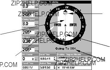
Create Waypoint on Map
1.Use the arrow keys to move the cursor crosshairs to the place where you want to make a waypoint.
2.Press WPT|WPT. The waypoint is saved and automatically given a name with a sequential number, like "waypoint 001." The waypoint symbol and number appear on the map.
Navigate To a Waypoint
You can select any waypoint visible on the Map Page with the cursor, then use the Navigate to Cursor command (we'll describe how later in this section.) However, you can avoid scrolling the map to pick your waypoint if you use the Find Waypoint commands:
1.Press WPT|??? to SAVED|ENT. To look up the nearest waypoint, press ??? to NEAREST|ENT; or, to look by name (and scroll through the entire waypoint list), press ENT. For this example, let's look by name.
2.If your waypoint list is a long one, you can spell out the waypoint name in the FIND BY NAME box to search for it. (Press ??? or ??? to change the first character, then press ??? to move the cursor to the next character and re- peat until the name is correct, then press ENT to jump to the list below.)
3.If the list is short, you can jump directly to the FIND IN LIST box by press- ing ENT. Use ??? or ??? to select the waypoint name, press ENT and the way- point information screen appears with the GO TO command selected.
4.To begin navigating to the waypoint, press ENT.
Navigation Page, navigating toward waypoint 004 and leaving a trail.
Set Man Overboard (MOB) Waypoint
One of boating's most terrifying events is having a friend or family member fall overboard. This situation can be deadly on any body of wa- ter. It's particularly dangerous at night or if you're out of sight of land.
127

Of course, the first thing to do is remain calm and then use all standard safety procedures to rescue the person.
This unit has a man overboard feature that shows navigation data to the location where the feature was activated. To activate it, press the ZOUT and ZIN keys at the same time. Your position at the time these keys are pressed is used as the man overboard position.
Caution:
Saving a new "Man Overboard" waypoint will overwrite the pre- vious "Man Overboard" waypoint.
Navigate Back to MOB Waypoint
Find your way back to the accident position with the Navigation Page or Map Page. When MOB is activated, the Navigation Page automati- cally shows the compass rose with its bearing arrow pointing toward the man overboard position, and the destination name says "Going To Man Overboard." The Map Page displays a Man Overboard waypoint, represented by a human figure, and the steering arrow points where to steer to reach that position.
Navigating to Man Overboard: Man Overboard Activated message (left). Navigation Page, center, Map Page (right). The victim is to the starboard of the vessel. The GPS shows which direction to go for the rescue.
The man overboard position is also stored in the waypoint list for fu- ture reference. It can be edited the same as any other waypoint. This prevents the inadvertent loss of the current Man Overboard position.
To cancel navigation to MOB, press MENU|MENU|??? to CANCEL NAVIGA- TION|ENT|??? to YES|ENT. The unit stops showing navigation information.
Navigate to Cursor Position on Map
The GO TO CURSOR command: navigates to the current cursor position on the map. It's a quick and handy way to navigate to anything you can see on the map display.
128

1.Use the cursor (controlled by the arrow keys) with the zoom in and zoom out keys to maneuver around the map until you find a location you want to go to.
2.Center the cursor over the location to select it. See the example in the following figure. (Many map items such as waypoints, Points of In- terest, towns, etc. can be "selected," and appear "highlighted" with a
Navigate to cursor. In this example, the cursor is centered on Oologah, Oklahoma.
3. Press MENU|ENT and the unit will begin navigating to the cursor location.
The Map Page will display a dotted line from your current position to the cursor position. The Navigation Page displays a compass rose showing navigation information to your destination. See the following examples.
The
129
To stop navigating to the cursor, use the Cancel Navigation command: press MENU|MENU|??? to CANCEL NAVIGATION|ENT|??? to YES|ENT. The unit stops showing navigation information.
Navigate to a Point of Interest
For POIs that are in view on the map, you can easily use the Navigate to Cursor command above; just use the cursor to select the POI.
The other method involves searching for POIs with the Find Waypoint command, launched with the WPT key. (See the searching example ear- lier in this section, or turn to Sec. 9, Searching, for detailed instructions on POI searches.)
To Navigate to a POI:
1.Press WPT, select the desired POI category, then press ??? to Subcate- gory.
2.Highlight the desired subcategory and press ENT. The Find By menu will appear with two search options: Name of Nearest.
3.Select the desired search option and press ENT. A list of POIs will appear. If you chose Nearest as the search option, use ??? ??? to select the desired POI and press ENT. If you chose to search by Name, use ??? ???, ??? ??? to input the POI name. When the name has been entered press ENT to access the POI list.
4.Select the desired POI and press ENT, which will open the Waypoint Information menu.
5.Highlight GO TO WAYPOINT and press ENT. The unit begins showing navigation information to the item.
To cancel navigation, press MENU|MENU|??? to CANCEL NAVIGATION|ENT|??? to YES|ENT. The unit stops showing navigation information.
Creating and Saving a Trail
A trail, or plot trail, is a string of position points plotted by the unit as you travel. It's a travel history, a record of the path you have taken. Trails are useful for repeating a journey along the same track. They are particularly handy when you are trying to retrace your trip and go back the way you came. On the screen, trails are represented by a solid line extending from the back of the current position arrow.
The unit is set at the factory to automatically create and record a trail while the unit is turned on. The unit will continue recording the trail until the length reaches the maximum trail point setting (default is 2,000, but the unit can record trails 9,999 points long). When the point limit is reached, the unit begins recording the trail over itself.
130
By default, the trail flashes once a second, making it easier to see against the background map. With the default auto setting, this unit creates a trail by placing a dot (trail point) on the screen every time you change di- rections. (The methods used for creating a trail and the trail update rate can both be adjusted or even turned off. See Sec. 8 for Trail Options.)
To preserve a trail from point A to point B, you must "turn off" the trail by making it inactive before heading to point C or even back to point A. When the current trail is set inactive, the unit automatically begins recording a new trail.
Active Visible symbol symbol
Sequence for saving a trail and beginning a new one. Left, My Trails command. Center, the Trails Menu. The arrow to the right of Trail 1 indicates the trail is "active," and the check to the left indicates the trail is visible on the map display. The right figure shows the Edit Trail menu, with the Active command selected.
To Save a Trail
1.Press MENU|MENU|??? to MY TRAILS|ENT.
2.Press ??? to the Active Trail Name|ENT.
3.Press ??? to ACTIVE|ENT. This unchecks the Active option.
4.To return to the previous page, press EXIT repeatedly. As you leave the Edit Trail menu, you will notice that a new trail starts with a new sequential number. In the example figure below, the new trail is num- ber 2, showing zero points. Note that Trail 1 is inactive, but it is still visible on the map.
131
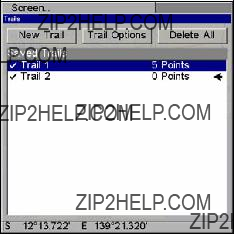
New trail, named "Trail 2," is created when Trail 1 is made inactive. Any new travel will be recorded in this trail, which is active and visi- ble. Trails do not need to be visible in order to be active.
You can save and recall up to 10 different plot trails, which can be cop- ied to your MMC for archiving or for transfer to your MapCreate soft- ware.
Tip:
Another quick way to stop recording one trail and begin a new one is to use the New Trail command: Press MENU|MENU|??? to MY
TRAILS|ENT|ENT.
Caution:
You also have the option of completely turning off trail re- cording, under the trail Options command. However, if the Up- date Active Trail option is turned off, it will cancel the auto- matic trail creation feature.
Displaying a Saved Trail
The active trail is automatically displayed on the map (the "Visible" option) with the factory default settings. You can selectively turn trail display off and on for any saved or active trail. In the Saved Trails List, visible trails have a check mark in front of the trail name.
To turn off trail display:
1.Press MENU|MENU|??? to MY TRAILS|ENT.
2.Press ??? to enter the Saved Trail list, then use ??? ??? to select the de- sired Trail Name|ENT.
3.Press ??? to ACTIVE|??? to VISIBLE|ENT. To return to the previous page, press EXIT repeatedly.
132
To turn on trail display:
1.Press MENU|MENU|??? to MY TRAILS|ENT.
2.Press ??? to enter the Saved Trail list, then use ??? ??? to select the de- sired Trail Name|ENT.
3.Press ??? to ACTIVE|??? to VISIBLE|ENT. To return to the previous page, press EXIT repeatedly.
Navigating Trails
There are three methods for following a trail: visual trailing, navigat- ing a trail (forward) and backtracking a trail (backward). Try each method to see which you prefer.
Visual trailing is the simplest method. It uses only the Map Page and requires no menu commands at all. The technique works the same if you are running a trail forward (from start to end) or backward (from end to start.) However, visual trailing provides no navigation informa- tion during the trip, such as the time to your destination.
The other two methods provide a full range of navigation data and work with both the Map Page and Navigation Page. The only difference between them is "navigating a trail" follows a trail forward (from start to end) while "backtracking" follows a trail in reverse (from end to start.)
When hiking at walking speed with a
Visual Trailing
1.On the Map Page, zoom (ZIN or ZOUT) so your flashing trail is visible.
2.Begin moving and watch the Map Page. Simply walk or steer so that your current position arrow traces along the trail you have just made.
Tip:
Generally, when using this method, the smaller the zoom range, the more accurately you will be able to steer along the trail.
Navigate a Trail
The following figures illustrate the menu sequence for navigating a trail.
1.Press MENU|MENU|??? to MY TRAILS|ENT.
2.Press ???|??? to enter the Saved Trail list, then use ??? or ??? to select the desired Trail Name|ENT.
133

3.Press ??? to DELETE TRAIL|??? to NAVIGATE|ENT.
4.Press ??? to NAVIGATE|ENT. The unit begins showing navigation infor- mation along the trail.
NOTE:
If you are already located at or near the beginning of your trail, the arrival alarm will go off as soon as you hit Enter. Press EXIT to clear the alarm and proceed.
5.Now, begin navigating with your unit.
6.When you reach your destination, be sure to cancel your navigation: press MENU|MENU|??? to CANCEL NAVIGATION|ENT. The unit asks if you're
Navigate a trail menu sequence: Fig. 1, My Trails command. Fig. 2, Trails Menu. Fig. 3, Edit Trail Menu. Fig. 4, Edit Route Menu with Navigate command highlighted for Trail 6. A trail is always converted to a "route" when you navigate the trail.
On the Map Page, the trail you are navigating is represented by a dot- ted line that alternates with a flashing solid line. The Navigation Page will also show the navigated trail as a dotted line. The bearing arrow on the compass rose points to the next waypoint on the trail.
As you travel, the arrival alarm will go off when you near a trail way- point, and the bearing arrow on the compass rose will swing around and point to the next trail waypoint. Press EXIT to clear the alarm.
134
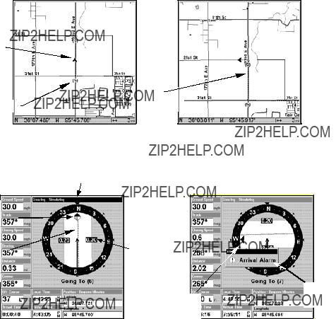
North ??
Present position arrow
Navigate trail, map views: Driver is northbound heading straight to- ward trail point 6 (left). Northbound driver has reached point 6 and has turned west to follow trail (right).
Track or compass heading indicator
Arrival Bearingalarm arrow
Navigate trail, navigation page (compass rose) views: driver is northbound heading straight toward trail point 6 (left); bearing arrow shows the trail point is due north (straight ahead.) Driver has reached trail point 6 and must turn west to follow the trail (right). Arrival alarm goes off and bearing arrow swings around toward the west and the next waypoint. The unit now shows navigation information to point 7, which is 2.02 miles away.
Navigate a Back Trail (backtrack)
1.Press MENU|MENU|??? to MY TRAILS|ENT.
2.Press ???|??? to enter the Saved Trail list, then use ??? or ??? to select the desired Trail Name|ENT.
3.Press ??? to DELETE TRAIL|??? to NAVIGATE|ENT.
4.Press ??? to NAVIGATE|??? to REVERSE|ENT|??? to NAVIGATE|ENT. The unit begins showing navigation information along the trail, in reverse.
135
NOTE
If you are already located at or near the end of your trail, the arri- val alarm will go off as soon as you hit ENT. Press EXIT to clear the alarm and proceed.
5.Now, begin navigating with your unit.
6.When you reach your destination, be sure to cancel your navigation: press MENU|MENU|??? to CANCEL NAVIGATION|ENT. The unit asks if you're sure; press ???|ENT.
Transfer Custom Maps and GPS Data Files
Custom Maps:
Custom maps work only from the MMC card or SD card. When a card containing a Custom Map File is loaded into the unit, the unit auto- matically loads the map into memory when the unit is turned on.
Instructions for copying Custom Map Files to an MMC are contained in the instruction manual for your MMC card reader and MapCreate soft- ware. For instructions on inserting an MMC into the unit, see Sec. 2, Installation/Accessories.
GPS Data files:
GPS Data Files contain waypoints, routes, trails and event marker icons. Instructions for copying GPS Data Files between your computer and an MMC are contained in the instruction manual for your MMC card reader and MapCreate software.
GPS data automatically recorded in the unit's internal memory must be saved to the MMC (as a GPS Data File) in order to store it on your personal computer. GPS Data Files stored on an MMC must be copied from the card to the unit's internal memory before the unit can read them. Here's how:
1.Insert the MMC into your unit. Press MENU|MENU|??? to SYSTEM SETUP|ENT|??? to TRANSFER MY DATA|ENT and the screen below appears.
2.The Transfer My Data menu includes a message which tells you if an MMC is present or not. If no MMC is present, you must first insert a card into the unit in order to activate the Load or Save commands.
To transfer data from the unit to the MMC: press ENT (for SAVE.)
To transfer data from the MMC to the unit: press ??? to LOAD|ENT.
136
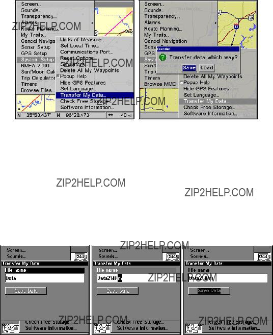
Transfer My Data highlighted (left). When transferring data (right) you will have the option of transferring the unit's data to a MMC card or loading the data on the MMC card into the unit.
3. Saving to MMC: To accept the default name "Data" for the GPS Data File, press ??? to SAVE DATA|ENT. If you want to rename the file (as shown in the following figures), press ENT to activate the selection box. Press ??? or ??? to change the first character, then press ??? to the next character and repeat until the name is correct. Then, press ENT|??? to
SAVE DATA|ENT.
The unit will display first a progress message followed by a completion message when the data transfer is finished. To return to the Page view, repeatedly press EXIT.
These figures (left to right) show the menu sequence for naming and saving a GPS Data File from the unit's memory to an MMC.
4. Loading to unit memory: There may be more than one GPS Data File (*.USR) on the card. To select a file, press ENT to activate the se- lection box, use ??? or ??? to highlight the file, then press ENT to accept the selection. Next, press ??? to LOAD DATA|ENT. The unit will display a com- pletion message when the data transfer is finished. To return to the Page view, press EXIT repeatedly.
137
Figure 1.
Figure 3.
Figure 2.
Figure 4.
These figures show the menu sequence for loading a GPS Data File from an MMC into the unit's memory.
Cancel Navigation
You can turn off any of the navigation commands after you reach your destination or at any other time by using the Cancel Navigation com- mand. Press MENU|MENU|??? to CANCEL NAVIGATION|ENT|??? to YES|ENT.
138

Section 7:
Advanced GPS Operations
Find Distance from different Locations
1.While on the Map Page press: MENU|??? to FIND DISTANCE|ENT.
2.Center your cursor over the position you want to find the distance to. A rubber band line appears, connecting your current position to the cursor's location. The distance along that line will appear in a
3.Press EXIT to return to regular operation.
Distance from Dallas to Little Rock is 292.2 miles (left). The distance from the boat's current position to the boat ramp is 0.52 miles (right).
Find Distance from Point to Point
You can also measure distance between two other points on the map.
1.While on the Map Page press: MENU|??? to FIND DISTANCE|ENT.
2.Center your cursor over the first position. (A rubber band line ap- pears, connecting your current position to the cursor's location.) Press ENT to set the first point, and the rubber band line disappears.
3.Move the cursor to the second position. The rubber band line reap- pears, connecting the first point you set to the cursor. The distance along that line will appear in the
4.Press EXIT to clear the command and return to the page screen. (Press EXIT once more to clear the cursor.)
139
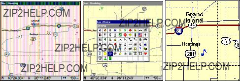
Icons
Icons are graphic symbols used to mark some location, personal point of interest or event. They can be placed on the map screen, saved and re- called later for navigation purposes. These are sometimes referred to as event marker icons. This unit has 42 different symbols you can pick from when creating an icon.
Icons are similar to waypoints, but they do not store as much informa- tion (like names) as waypoints do. You can't use a menu to navigate to icons as you can with waypoints. (But, you can use the map cursor and navigate to any icon on the map.)
You can create an icon at the cursor position on the map, or at your current position while you are navigating.
Create Icon on Map
1.Use the arrow keys to move the cursor to the place where you want to make an icon.
2.Press ENT and the Select Icon Symbol menu will appear.
3.Press ??? ??? , ??? ??? to select your icon symbol and press ENT. The icon appears on the map.
Cursor selects icon location (left). Select Icon Symbol menu (center), Music note icon on map (right). (Cursor has been moved for clarity.)
Create Icon at Current Position
1.While you are traveling, press ENT and the Select Icon Symbol menu will appear.
2.Press ??? ???, ??? ??? to select your icon symbol, then press ENT. The icon appears on the map.
Delete an Icon
You can delete all the icons at one time, delete all icons represented by a particular symbol or use the cursor to delete a selected icon from the map.
140
1.Press MENU|??? to DELETE MY ICONS|ENT.
2.Press ??? to DELETE ALL ICONS, DELETE BY SYMBOL, or DELETE FROM MAP and
press ENT.
Delete icons menu.
The Delete All Icons command will ask if you are sure. Press ??? to YES|ENT. All icons will be deleted from the map.
The Delete by Symbol command will launch the Select Symbol menu. Press ??? or ??? or ??? or ??? to select the icon symbol to delete, then press ENT. A message appears saying all icons with the selected symbol have been deleted.
The Delete From Map command will prompt you to move the cursor over an icon to select it. After selecting the icon, press ENT and it dis- appears from the map.
Navigate to an Icon
Use the cursor to select the desired icon on the map, then use the Navi- gate to Cursor command.
1.Use arrow keys to center cursor crosshairss over the icon.
2.To navigate to the selected icon location: press MENU|ENT|EXIT. Fol- low course line on the Map Page or the compass bearing arrow on the Navigation Page.
Routes
A route is a series of waypoints, linked together in an ordered sequence to mark a course of travel. You can visualize a route as a string of beads. The beads represent waypoints and the string represents the course of travel connecting waypoint to waypoint.
141

The course from one waypoint to the next is a leg. Routes are composed of one or more legs. The legs of all GPS routes are based on straight lines between waypoints.
A route provides the automatic capability to navigate through several waypoints without having to reprogram the unit after arriving at each waypoint. Once programmed into the GPS unit, a route provides the option of navigating forward through the route waypoints or in reverse order (you can even begin navigating in the middle of a route!)
Create and Save a Route
You have the option of creating and editing a route in the unit or you can make a route on your computer with our MapCreate software.
MapCreate is the easiest method for preparing a route, simply because your PC's larger screen, keyboard and mouse are easier to manipulate than the unit.
To load a MapCreate route into the unit, follow instructions in MapCre- ate's manual for creating a route and saving it as part of a GPS Data File (file format *.usr). Copy the GPS Data File to an MMC and insert the MMC in the unit. (See Sec. 2 for instructions on installing MMCs. To load the GPS Data File into the unit's memory, see the entry on Transfer Cus- tom Maps & GPS Data Files in Sec. 6, Basic GPS Operations.)
Routes Created in the Unit
You can create a route by selecting existing waypoints from the way- point list or you can set a series of route waypoints on the map with cursor arrows and the Enter key. In this example, we'll create a route from the map.
Route Planning command on Main Menu (left). Routes screen (right).
142
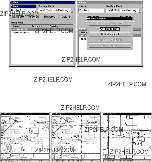
1.From the NAVIGATION PAGE, press MENU|ENT or from the MAP PAGE, press MENU|MENU|??? to ROUTE PLANNING|ENT|ENT.
2.Press ??? to (END OF ROUTE)|ENT|??? to ADD FROM MAP|ENT. The Map Page appears with the cursor showing.
Edit Route menu (left). Edit Route Waypoints menu (right) with Add From Map command selected.
3. Use the Zoom keys and arrow keys to move the map and cursor until the cursor is centered on the spot where you want your route to begin. (If you are starting at your current position or the current cursor posi- tion, you are already at the starting spot.)
Route creation sequence, from left: Fig. 1. Set route waypoint (1) at 11th St. & 145th Ave. Fig. 2. Zoom in; move cursor north to set point (2) at 145th & Admiral. Fig. 3. With point (2) set, move cursor east to mark interstate
143

4. Set the first route waypoint: press ENT. In this example, we started our route at the intersection of 11th Street and 145th E. Ave. The route ends at a public hunting area next to a river. (Our route creation ex- ample is illustrated in the following figures.)
Route creation sequence, continued: Fig. 4. Point (3) set at
5.Move the cursor to the next point in the route, a spot where you need to turn or change direction, and press ENT to set the next waypoint.
6.Repeat step five until the route reaches your destination.
7.To save your route, press EXIT. The unit reverts to the Edit Route screen, with the route automatically named "Route 1" and stored in the unit's internal memory. (In our example, Route 1 already existed, so the unit automatically made "Route 2.")
You can edit the route and run other commands, but if you are finished with the route for now, return to the last page displayed by pressing EXIT repeatedly.
Delete a Route
1.From the NAVIGATION PAGE, press MENU|ENT or from the MAP PAGE press
MENU|MENU|??? to ROUTE PLANNING|ENT.
2.Press ??? to route name|ENT.
3.Press ??? to NAVIGATE|ENT|??? to DELETE|ENT|??? to YES|ENT.
Tip:
You can also delete all routes at once:
1.From the NAVIGATION PAGE, press MENU|ENT or from the MAP PAGE press MENU|MENU|??? to ROUTE PLANNING|ENT.
2.Press ??? to DELETE ALL|ENT|??? to YES|ENT.
144
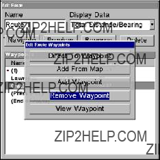
Edit a Route Name
1.From the NAVIGATION PAGE, press MENU|ENT or from the MAP PAGE press
MENU|MENU|??? to ROUTE PLANNING|ENT.
2.Press ??? to route name|ENT|ENT.
3.Press ??? or ??? to change the first character, then press ??? to move the cursor to the next character and repeat until the name is correct, then press ENT. Return to the previous page by pressing EXIT repeatedly.
Edit Route Waypoints
You can edit the route by adding and removing waypoints.
1.From the NAVIGATION PAGE, press MENU|ENT or from the MAP PAGE press
MENU|MENU|??? to ROUTE PLANNING|ENT.
2.Press ??? to route name|ENT|??? to ROUTE WAYPOINTS LIST. Use ??? ??? to se- lect a waypoint and press ENT.
Edit Route Waypoints menu.
3. Use ??? ??? to select a command from the Edit Route Waypoints menu and press ENT. Add From Map lets you insert a waypoint in the route by clicking on a map location with the cursor. Add Waypoint calls up the Waypoint List so you can insert a waypoint from the list. Remove Waypoint will delete the waypoint from the route. View Waypoint will show you where the selected waypoint is on the map.
NOTE:
When adding waypoints to a route, the inserted waypoints will ap- pear in the route in front of the waypoint you have selected. To in- sert waypoints at the end of the route, make sure to select "(End of route)" before adding them.
145
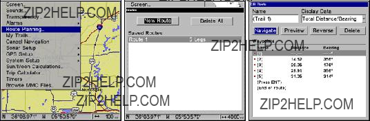
Route Planning on Main Menu (left). Routes menu (center). Edit Route menu (right). Navigate is selected on Edit Route menu.
Navigate a Route
1.From the NAVIGATION PAGE, press MENU|ENT or from the MAP PAGE, press MENU|MENU|??? to ROUTE PLANNING|ENT.
2.Press ??? to select route name|ENT|??? to NAVIGATE|ENT.
3.Upon arrival at your destination, cancel navigation:
press MENU|MENU|??? to CANCEL NAVIGATION|ENT|??? to YES|ENT.
The following figures show what the Navigation Page and Map Page look like while navigating a route.
Navigate a Route in Reverse
Here's how you run a route backward, from the end waypoint to the beginning waypoint:
1.From the NAVIGATION PAGE, press MENU|ENT or from the MAP PAGE, press MENU|MENU|??? to ROUTE PLANNING|ENT.
2.Press ??? to select route name|ENT|??? to NAVIGATE|??? to RE-
VERSE|ENT|??? to NAVIGATE|ENT.
3. Upon arrival at your destination, cancel navigation:
press MENU|MENU|??? to CANCEL NAVIGATION|ENT|??? to YES|ENT.
146

Figure 1.
Figure 3.
Figure 2.
Figure 4.
Navigating along a route: Fig. 1 shows the Navigation Page at the start of a route, heading straight for the first waypoint (Wpt 1). In Fig. 2, the traveler has arrived at Wpt 1; the arrival alarm has been triggered and the bearing arrow on the compass rose has turned to point toward Wpt 2, off to the east. In Fig. 3 the traveler has turned east on his new course and is heading straight for Wpt 2, which is 2.37 miles away. Fig. 4 shows route navigation on the Map Page. In this figure, the traveler has reached Wpt 2 and is
Trails
Delete a Trail
This is the command used to delete a trail: Press MENU|MENU|??? to MY TRAILS|ENT|??? to trail name|ENT|??? to DE-
LETE TRAIL|ENT|??? to YES|ENT.
Tip:
You can also delete all trails at once:
1.Press MENU|MENU|??? to MY TRAILS|ENT.
2.Press ??? to DELETE ALL|ENT|??? to YES|ENT.
147
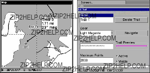
Edit a Trail Name
To edit a trail name: press MENU|MENU|??? to MY TRAILS|ENT|??? to trail name|ENT|ENT. Press ??? or ??? to change the first character, then press ??? to the next character and repeat until the name is correct. Press ENT then EXIT repeatedly to return to the previous page display.
Tip:
You can quickly call up the Edit Trail menu by selecting a trail on the map with the cursor. Simply move the cursor over a trail and a
Trail selected with map cursor (left). The
The Edit Trail menu (right).
Edit a Trail Color
To edit a trail color: press MENU|MENU|??? to MY TRAILS|ENT|??? to trail name|ENT|??? to COLOR|ENT. Press ??? or ??? to select a color style, then press ENT. Press EXIT repeatedly to return to the previous page display.
Edit a Trail Pattern
To edit a trail pattern: press MENU|MENU|??? to MY TRAILS|ENT|??? to trail name|ENT|??? to PATTERN|ENT. Press ??? or ??? to change the first character, then press ??? to the next character and repeat until the pattern is cor- rect. Press ENT, then EXIT repeatedly to return to the previous page dis- play.
148
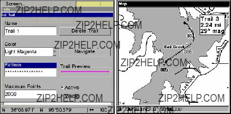
Edit Trail Menu with Pattern option selected (left). Edited trail with dotted line pattern (right).
Utilities
Utilities are useful tools for traveling or for outdoor activities.
Alarm Clock
To access the unit's alarm clock: press MENU|MENU|??? to TIMERS|ENT|???
to ALARM CLOCK|ENT.
Sun/Moon Rise & Set Calculator
To get to the Sun/Moon menu: press MENU|MENU|??? to SUN/MOON CALCU-
LATIONS|ENT.
Trip Calculator
To get to the Calculator menu: press MENU|MENU|??? to TRIP CALCULA-
TOR|ENT.
Trip Down Timer
To get to the Down Timer menu: press MENU|MENU|??? to TIMERS|ENT|???
to DOWN TIMER|ENT.
Trip Up Timer
To get to the Up Timer menu: press MENU|MENU|??? to TIMERS|ENT|ENT.
Waypoints
To delete a waypoint from waypoint list:
1, Press WPT|ENT|ENT|ENT|??? to waypoint name|ENT|??? to DELETE WAY- POINT|ENT|??? to YES|ENT. To return to the previous page, press
EXIT|EXIT.
149
To delete a waypoint from the map:
1.Use the arrow keys to select the waypoint with the cursor.
2.Press WPT|??? to DELETE WAYPOINT|ENT|??? to YES|ENT. To return to the previous page and clear the cursor, press EXIT.
To delete all waypoints at one time:
1. Press MENU|MENU|??? to SYSTEM SETUP|ENT|??? to DELETE ALL MY WAY-
POINTS|ENT|??? to YES|ENT. To return to the previous page, press
EXIT|EXIT.
Edit a Waypoint
To edit waypoint name:
1. Press WPT|ENT|ENT|ENT|??? to waypoint name|ENT|??? to EDIT WAY- POINT|ENT|ENT.
2. Press ??? or ??? to change the first character, then press ??? to the next character and repeat until the name is correct. Press ENT then EXIT re- peatedly to return to the previous page display.
To edit waypoint symbol:
1. Press WPT|ENT|ENT|ENT|??? to waypoint name|ENT|??? to EDIT WAY-
POINT|ENT|??? to CHOOSE SYMBOL|ENT.
2. Use arrow keys to select desired symbol and press ENT. To return to the previous page, press EXIT repeatedly.
To edit waypoint position:
1. Press WPT|ENT|ENT|ENT|??? to waypoint name|ENT|??? to EDIT WAY-
POINT|ENT.
2.Latitude: press ??? to LATITUDE|ENT. Press ??? or ??? to change the first character, then press ??? to the next character and repeat until the lati- tude is correct. Press EXIT.
3.Longitude: press ??? to LONGITUDE|ENT. Press ??? or ??? to change the first character, then press ??? to the next character and repeat until the lon- gitude is correct. Press EXIT.
4.When latitude and longitude are correct, return to the previous page: press EXIT repeatedly.
Selecting a Waypoint
To select a waypoint on the map (for navigating to, for editing, etc.,) use the arrow keys and center the cursor over the waypoint. A highlighted halo will appear around the waypoint.
150
Create Waypoint by Entering a Position
1.Press WPT|??? to SUBCATEGORY column|??? to NEW|ENT.
2.Press ??? to ENTERED POSITION|ENT|??? to CREATE|ENT.
3.Press ??? to LATITUDE|ENT. Enter the latitude by pressing ??? or ??? to change the first character, then press ??? to the next character and re- peat until the latitude is correct. Press ENT.
New Waypoint screen (left). Edit Waypoint menu with Latitude high- lighted (right).
4.Press ??? to LONGITUDE|ENT. Enter the longitude by pressing ??? ??? to change the first character, then press ??? to the next character and repeat until the longitude is correct. Press ENT. To edit the waypoint's name, altitude, depth or symbol, proceed to Step 5. If you want to see the way- point on the map, press EXIT, select GO TO WAYPOINT or FIND ON MAP and press ENT. If you select Go to Waypoint, a route will be automatically be created directing you to the new waypoint. If you choose Find on Map, the map screen will appear with the cursor crosshairss centered on the waypoint you created.
5.You can edit the waypoint's Name, Altitude or Depth by highlighting the desired category and pressing ENT. Use ??? ??? to change the first character, then press ??? to the next character and repeat until the de- sired name, altitude or depth has been entered. Press ENT.
6.To edit the waypoint's symbol, highlight CHOOSE SYMBOL and press ENT. The Icon Window will appear with 63 symbols. Select the desired symbol and press ENT.
7.Press EXIT, which will open the Waypoint Information menu with up to four options: Go To Waypoint, Find on Map, Edit Waypoint and De- lete Waypoint. Select the desired option and press ENT.
151
Set a Waypoint by Average Position
This feature sets a waypoint at the current position after taking several position readings and averaging them.
This boosts waypoint position accuracy by helping to eliminate errors caused by atmospheric conditions and other factors.
1.Press WPT|??? to SUBCATEGORY column|??? to NEW|ENT.
2.Press ??? or ??? to AVERAGE POSITION|ENT|press ??? to CREATE|ENT.
3.Wait while the unit takes points to average for the position. (The greater the number of points, the greater the accuracy.) When the desired number of points accumulates, press ENT to create and save the waypoint.
4.The Edit Waypoint menu appears. You can simply save the waypoint by pressing EXIT|EXIT or you can edit the waypoint.
Set a Waypoint by Projecting a Position
This feature sets a waypoint at a point located a specific distance and bearing from a reference position. The reference position can be se- lected from your waypoint list, a map feature or from the Points of In- terest list.
1.Press WPT|??? to SUBCATEGORY column|??? to NEW|ENT.
2.Press ??? to PROJECTED POSITION|ENT|??? to CREATE|ENT.
3.Press ??? to CHOOSE REFERENCE|ENT. Use ??? and ??? to select a waypoint, map feature or Point of Interest. When the point has been selected, press ENT and you will be directed to the Waypoint information menu. There will be two options: Set Reference or Find on Map. Highlight Set Reference and press Enter.
4.Press ??? to DISTANCE|ENT. Press ??? or ??? to change the first character, then press ??? to the next character and repeat until the distance is cor- rect. Press ENT.
5.Press ??? to BEARING|ENT. Press ??? or ??? to change the first character, then press ??? to the next character and repeat until the bearing is cor- rect. Press ENT.
6.Press ??? to PROJECT|ENT. The Edit Waypoint menu appears. You can simply save the new projected waypoint by pressing EXIT|EXIT or you can edit the waypoint. (Press EXIT|ENT if you want to immediately be- gin navigating to the new waypoint.)
152

Section 8:
System & GPS Setup Options
Alarms
This unit has several GPS alarms. The factory default setting has all of these but the anchor alarm turned on. You can turn the alarms off and on and change their distance settings.
You can set an arrival alarm to flash a warning message and sound a tone when you cross a preset distance from a waypoint. For example, if you have the arrival alarm set to .1 mile, then the alarm will flash a message when you come within .1 mile of the recalled waypoint.
The off course alarm warns you when your track drifts too far to the right or left of the course line to the waypoint. For example, if the alarm is set to .1 mile, then the alarm flashes a message if you drift .1 of a mile or more to the right or left of the line to the waypoint.
The anchor alarm is triggered when you drift outside of a preset radius. Again, using the .1 mile as an example, if you're anchored and your boat moves more than .1 of a mile, the alarm will flash a message and sound a tone.
Alarms command (left). Alarm menu (right).
To change alarm settings:
1.Press MENU|MENU|??? to ALARMS|ENT|ENT.
2.Scroll ??? ??? to select the desired category, then press ENT to check or clear the Enabled box. This turns the alarm on (checked) or off (un- checked.)
153
3.To change distance settings, scroll ??? ??? to select the desired category, then press ??? |ENT to activate the distance dialog box. Use ??? ??? to change the first character, then press ??? to the next character and re- peat until the name is correct.
4.When your adjustments are finished, return to the last page dis- played by repeatedly pressing EXIT.
IMPORTANT ALARM NOTES
Anchor Alarm - The anchor alarm may be triggered even when you are sitting still. This typically happens when using small (less than
.05 mile) anchor alarm ranges.
Arrival Alarm - If you set the arrival alarm's distance to a small number and you run a route (see the Navigate Routes segment), this unit may not show navigation data to the next waypoint, once you arrive at the first one. You may not be able to come close enough to the first waypoint to trip the arrival alarm.
Auto Satellite Search
To lock on to the satellites, the GPS receiver needs to know its current position, UTC time and date. (Elevation [altitude] is also used in the equation, but it's rarely required to determine a position.) It needs this data so that it can calculate which satellites should be in view. It then searches for only those satellites.
When your GPS receiver is turned on for the first time, it doesn't know what your position or elevation (altitude) is. It does know the current UTC time and date since these were programmed into it at the factory and an internal clock keeps the time while the unit is turned off. (If the time and/or date are incorrect, you can set them using the "Set Local Time" menu.)
The unit begins searching for the satellites using the above data that it acquired the last time it was turned on. This probably was at the fac- tory. Since it's almost certain that you're not at our factory, it's proba- bly looking for the wrong satellites.
If it doesn't find the satellites it's looking for after approximately one minute, it switches to Auto Search. The receiver looks for any satellite in the sky. Due to advanced technology, the auto search time has shrunk significantly from the early days of GPS.
Once the unit locks on to the satellites, it should take less than a minute to find your position the next time it's turned on, as long as you are ap- proximately 100 miles from the last location it was used.
154

MMC File Browser.
Check MMC Files and Storage Space
To check MMC Files:
1.Press MENU|MENU|??? to BROWSE MMC FILES|ENT.
2.Use??? ??? to browse through the files. Highlight a file and press ENT to select it.
3.Press EXIT repeatedly to return to the main display.
Communications Port Configuration
The unit has one NMEA 0183 version 2.0 compatible communication port, or com port for short. The Com Port Menu, which is accessed from the System Setup Menu, allows you to configure the communications port to send or receive data from another electronic device, such as an autopilot. The com port can be used for either NMEA, or SiRF Binary data transfer.
Communications Port highlighted on System Setup menu (left). Baud Rate selected on Communications Port menu (right).
155
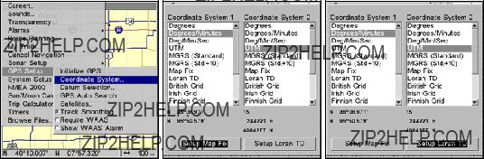
For connectors and wiring information for another device, see page 36. For assistance in configuring the unit to communicate with another device, consult the factory. Customer service phone numbers are in the back of this manual.
Configure NMEA
You can configure the unit to use specific NMEA sentences.
1.Press MENU|MENU|??? to SYSTEM SETUP|ENT.
2.Press ??? to COMMUNICATIONS PORT|ENT|??? to CONFIGURE NMEA|ENT.
3.A menu appears showing the prefixes of the available NMEA sen- tences. A check mark next to a prefix means the prefix is in use. Use ??? ???, ??? ??? to select a prefix, then press ENT to turn off the prefix. (Press ENT again to check the box and turn on a prefix.)
4.When the desired prefixes are checked or unchecked, press EXIT re- peatedly to return to the previous page.
NOTE:
Placing a check in the checkbox next to Radar at the bottom of the Communications Port menu will set the Baud Rate to the default Radar Baud Rate setting.
Coordinate System Selection
The Coordinate System Menu lets you select the coordinate system to use when displaying and entering position coordinates.
Menus for changing coordinate system used to display positions.
To get to Coordinate System Selection:
1.Press MENU|MENU|??? to GPS SETUP|ENT.
2.Press ??? to COORDINATE SYSTEM|ENT.
This unit can show a position in degrees (36.14952??); degrees, minutes and thousandths of a minute (36?? 28.700'); or degrees, minutes, seconds and tenths of a second (36?? 28' 40.9"). It can also show position in: UTM
156
(Universal Transverse Mercator) projection; MGRS (Standard); MGRS (Standard + 10); Map Fix; Loran TD; British, Irish, Finnish, German, New Zealand, Swedish, Swiss, Taiwan and Greek.
UTM's are marked on USGS topographic charts. This system divides the Earth into 60 zones, each 6 degrees wide in longitude.
British, Irish, Finnish, German, New Zealand, Swedish, Swiss, Taiwan, and Greek grid systems are the national coordinate system used only in their respective countries. In order to use these grid systems, you must be in the respective country. This unit will pick the matching datum for you when you select the grid. See the entry on Map Datum Selection for more information.
The Military Grid Reference System (MGRS) uses two grid lettering schemes, which are referred to as standard and standard + 10 MGRS on this unit. Your position and datum in use determines which one to use. If you use standard, and your position is off significantly, then try the alternate.
NOTE:
When the position format is changed, it affects the way all positions are shown on all screens. This includes waypoints.
To change the coordinate system
1.Press ENT while COORDINATE SYSTEM is highlighted.
2.Use ??? ??? to highlight the desired format and press ENT. Press EXIT repeatedly to return to the map display.
To set up Loran TD:
If the Loran TD conversion is chosen, you must enter the local Loran chain identification for the master and slaves. Highlight SETUP LORAN TD at the bottom of the Coordinate System menu and select the ID. Press EXIT to close this menu.
157

Configure Loran TD menu.
Map Fix
Map Fix is used with charts or maps. This system asks for a reference position in latitude/longitude, which you take from a marked location on the map. It then shows the present position as distance on the map from that reference point.
For example, if it shows a distance of UP 4.00" and LEFT 0.50", you then measure up four inches and to the left a
To configure a map fix:
To use this format, you need to follow these steps in order. First, take your map of the area and determine a reference latitude/longitude. (Note: in order for this system to work, the latitude/longitude lines must be parallel with the edge of the map. USGS maps are parallel, others may not be. Also, this works better with smaller scale maps, such as 1:24000.) The reference position can be anywhere on the map, but the closer it is to your location, the smaller the numbers will be that you'll have to deal with.
Once you've decided on a reference position, you can save it as a waypoint. See the waypoint section for information on saving a waypoint. Save the reference position as a waypoint. Exit from the waypoint screens.
1.Press MENU|MENU|??? to GPS SETUP|ENT.
2.Press ??? to COORDINATE SYSTEM|ENT.
3.Press ??? to SETUP MAP FIX|ENT. The screen below appears, and MAP SCALE is highlighted.
158
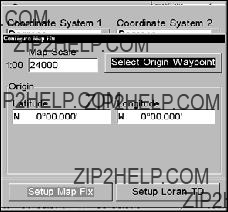
4. Press ENT and enter the map's scale. This is generally at the bottom of the paper map. It is shown as a ratio, like 1:24000. Press EXIT and the unit to return to the Configure Map Fix screen.
Configure a map fix so the unit can find your position on a printed chart or topographical map.
5.Press ??? to SELECT ORIGIN|ENT|ENT|ENT to bring up the waypoint list. Select the waypoint that you saved the reference point under and press ENT. The unit displays a waypoint information screen with the com- mand SET AS ORIGIN selected.
6.Press ENT and the unit returns to the Configure Map Fix menu. Fi- nally, press EXIT to close this menu.
7.Press ??? to COORD SYSTEM|ENT, select MAP FIX from the list and press ENT|EXIT. All position information now shows as a distance from the reference point you chose.
Customize Page Displays
Every Page display option except Full Map (on the Map Page) has cus- tomizable data boxes to provide constant
The data available from your unit is divided into categories in the Data Viewer menu. These categories include GPS Data, Navigation, Trip Calculator, Time, Sonar and Miscellaneous. You can select items from any of these categories for display in any data box ??? the category divi- sions are only there to help you sort through the information.
To change data box information:
1.On the Page display you wish to change, press MENU|??? to CUSTOM- IZE|ENT. A data box name flashes, indicating it is selected.
2.Press ENT to change the box or hit ???, ???, ??? ??? to select another box, then press ENT. You will see a list of categories with "+" or
159
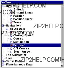
Customize Menu, with "GPS Data" and "Navigation" categories expanded.
Selecting the category name and pressing ENT will show the category's contents, so you can choose items within it. An expanded category (one with a
3.Expand any categories that might contain data you want to display. Press ??? ??? to select a different data option.
4.With the new option highlighted, press ENT to switch the contents of the box to the new data type and press EXIT. You can now select an- other box to change. When you are finished with the settings, press EXIT again to end the Customize command, and the box name stops flashing.
NOTE:
A Page display can show a limited number of data boxes. You can not add or remove data boxes.
GPS Simulator
The GPS simulator lets you use the unit as if you were outdoors navigat- ing somewhere. It's a great way to practice using your unit. You can set the starting location by entering latitude/longitude (Starting Position) or from a stored waypoint, map place or POI. You can steer your position and change speed on the map by using the arrow keys (STEER WITH ARROWS command) or by setting the track and speed in the dialog boxes provided on the simulator menu screen.
To turn on the GPS Simulator:
1.Press MENU|MENU, highlight SYSTEM SETUP and press ENT.
2.Select SIMULATORS and press ENT.
160
The GPS Simulator menu.
The GPS Simulator page will appear. The page has dialog boxes that allow you to change the Track, Speed, Altitude, Latitude and Longitude of your simulation.
You can begin your simulation at a waypoint by using the Select Start- ing Waypoint command or direct the simulation manually by using the Steer with Arrows command, which will place Steer with Arrow boxes on the main display.
Tip:
The Initialize GPS command offers another way to choose a desired location to begin a simulation. The Initializing GPS command al- lows you to move the center display arrow to any location on the map. We will explore the Initialize GPS command in more detail in the Initialize GPS entry below.
3. When all settings have been set to your preferences, turn on the simulator on by highlighting the GPS SIMULATOR ON box and pressing ENT. Press EXIT repeatedly to return to the map display. Repeat Steps
NOTE:
A message and tone appear periodically, warning you that the simulator is on. To turn the simulator off, repeat the above steps or turn the unit off.
Steer with Arrows
When you are using the Steer with Arrows command, you can press EXIT to clear the steering and speed boxes from the screen while con- tinuing the simulation. This action will allow you to use the map cursor during a simulation. To turn steering and speed boxes back on again,
161
return to the GPS Simulator menu, highlight the STEER WITH ARROWS command, press ENT. Press EXIT repeatedly to return to the previous page.
Simulating Trail or Route Navigation
In Simulator mode, your unit can automatically follow a trail or route without manual steering if you use these steps:
1.From the Map Page, go to the simulator menu. Pick a STARTING POSI- TION at or near the beginning of your trail/route. Enter an approximate TRACK (shown in compass degrees) that will point you toward the start of the trail/route.
2.Set SPEED to zero. Select STEER WITH ARROWS command and press ENT, which turns on the simulator and returns you to the Map Page.
3.Begin navigating along the trail/route. (If you are close enough to the first waypoint, the arrival alarm will usually go off as soon as naviga- tion begins. Press EXIT to clear the alarm.) When navigation starts,
press ??? to increase speed to the desired setting.
4. Press EXIT to turn off the steering and speed boxes. The unit will now automatically steer along the trail or route. Cancel navigation when you arrive at your destination.
Hide GPS Feature
If there is no GPS antenna/receiver module attached to this unit, the GPS menus and features can be hidden from view with this command. The default setting is off, allowing you to rotate between the Sonar Page and the GPS pages and features.
To Hide GPS Features:
1.Press MENU|MENU|??? to SYSTEM SETUP|ENT.
2.Highlight HIDE GPS FEATURES and press ENT. The GPS menus and pages are now hidden.
To restore GPS Features, press MENU|MENU|??? to SHOW GPS FEA- TURES|ENT. The GPS menus and pages are available once again.
Initialize GPS
This command is handy when you are practicing in simulator mode. (See the entry in this section for GPS Simulator.) In simulator mode, this command makes the unit operate as if it is sitting someplace other than its actual location. So, you and your unit could be located in Kansas City, but easily practice navigating in the ocean off Islamorada, Florida.
162
To Initialize GPS:
1.Press MENU|MENU|??? to GPS SETUP|ENT|ENT.
2.A message appears, prompting you to move the cursor to the desired location. Move the cursor to the desired location and press ENT.
When the message automatically clears, follow the message instruc- tions.
3. In a moment, your present position marker arrow appears on the map in the location you selected with the cursor. The unit will consider that spot as its last known position until changed by either a live satel- lite
Map Auto Zoom
This unit has an auto zoom feature that eliminates much of the button pushing common with other brands of GPS receivers. It works in con- junction with the navigation features.
First, start navigation to a waypoint. (See the waypoint section for more information on navigating to a waypoint.) Then, with the auto zoom mode on, the unit zooms out until the entire course shows, from the present position to the destination waypoint. As you travel toward the destination, the unit automatically begins zooming in ??? one zoom range at a time ??? always keeping the destination on the screen.
To turn on Auto Zoom:
1. From a MAP PAGE, press MENU|??? to AUTO ZOOM|ENT|EXIT. Repeat these steps to turn it off.
Map Data
This menu lets you turn the map off, if desired (which turns the map screen into a GPS plotter); turn off or on the
163

Map Menu (left). Map Data Menu (right).
To access Map Data menu:
From the Map Page, press MENU|??? to MAP DATA|ENT.
To show Map Data
1.From the Map Page, press MENU|??? to MAP DATA|ENT.
2.Press ENT to open the EARTH MAP DETAIL selection list, and choose how much detail you want ??? from Off (so the unit operates like a GPS plot- ter) to High.
3.After the option is set, press EXIT repeatedly to return to the page display.
To turn on/off
1.From the Map Page, press MENU|??? to MAP DATA|ENT.
2.Press ??? to POPUP MAP INFORMATION. With the option highlighted, press ENT to check it (turn on) or uncheck it (turn off.)
3.After the option is set, press EXIT|EXIT to return to the page display.
To turn on/off Draw Map Boundaries
1.From the Map Page, press MENU|??? to MAP DATA|ENT.
2.Press ??? to DRAW MAP BOUNDARIES. With the option highlighted, press ENT to check it (turn on) or uncheck it (turn off.)
3.After the option is set, press EXIT|EXIT to return to the page display.
To turn on/off Fill Water With White
1.From the Map Page, press MENU|??? to MAP DATA|ENT.
2.Press ??? to FILL WATER WITH WHITE. With the option highlighted, press ENT to check it (turn on) or uncheck it (turn off.)
3.After the option is set, press EXIT|EXIT to return to the page display.
164
Map Overlays (Range Rings; Lat/Long Grid)
The map screen can be customized with four range rings and/or grids that divide the plotter into equal segments of latitude and longitude.
Range rings are handy for visually estimating distances on the map. The ring diameters are based on the current zoom range. For example: at the 100 mile zoom, the screen will show two rings with your current position in the center. The large ring touching the left and right sides of the screen is 100 miles in diameter (same as the zoom range). The second smaller ring is 50 miles in diameter (always 1/2 the zoom range).
The distance from your current position to the smaller ring (the ring's radius) is 25 miles (always 1/4 the zoom range). With the arrow keys and map cursor, you can scroll the map to see the third and fourth rings. In this example, the distance to the third ring is 75 miles and distance to the fourth ring is 100 miles from your current position.
To turn on/off range rings:
1.From the Map Page, press MENU|??? to MAP DATA|ENT.
2.Press ???, ??? to RANGE RINGS. With the option highlighted, press ENT to check it (turn on) and uncheck it (turn off.)
3.After the option is set, press EXIT|EXIT to return to the page display.
To turn on/off Lat/Long Grid lines:
1.From the Map Page, press MENU|??? to MAP DATA|ENT.
2.Press ???, to LAT/LON GRID LINES. With the option highlighted, press ENT to check it (turn on) and uncheck it (turn off.)
3.After the option is set, press EXIT|EXIT to return to the page display.
Map Datum Selection
Maps and charts are based on a survey of an area covered by the map or chart. These surveys are called Datums. Maps using different da- tums will show the same latitude/longitude in different locations.
All datums are named. The GPS system is based on the
1.Press MENU|MENU|??? to GPS SETUP|ENT|??? to DATUM SELECTION|ENT.
2.Use ??? ??? to select the desired datum, then press ENT.
3.To return to the last page displayed, press EXIT|EXIT.
A list of the datums used by this unit is in the back of this manual.
165
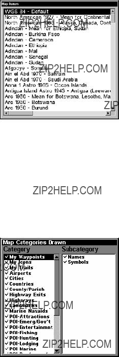
The Map Datum Menu.
Map Detail Category Selection
This menu determines which of the mapping features are shown on the screen. This includes: waypoints, trails, icons, cities, highways, etc. You can turn on or off any of these items to customize the map.
To get to Map Categories:
1.From the Map Page, press MENU|??? to MAP CATEGORIES DRAWN|ENT.
2.Press ??? ??? to select a category or press ??? then press ??? ??? to select a subcategory. Press ENT to turn it off (no check) or on (checked.)
3.To return to the map display, press EXIT|EXIT.
The Map Categories Drawn Menu.
Map Orientation
By default, this receiver shows the map with north always at the top of the screen. This is the way most maps and charts are printed on paper.
166
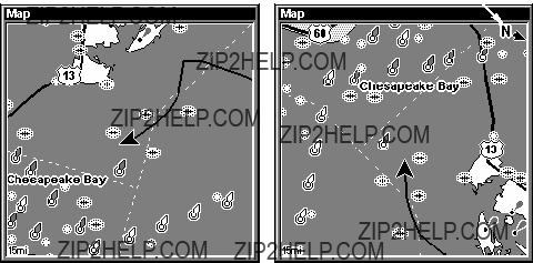
In Track Up mode, map shows "N" and arrow to indicate north.
Map page shown in North Up mode (left) Map page shown in Track Up mode (right).
This is fine if you are always traveling due north. What you see to your left corresponds to the left side of the map, to your right is shown on the right side of the map, and so on. However, if you travel any other direction, the map doesn't line up with your view of the world.
To correct this problem, a
Another option is
To change map orientation:
1.From the Map Page, press MENU|??? to MAP ORIENTATION|ENT.
2.Use ??? ??? to select the desired mode, then press ENT.
3.Press EXIT|EXIT to return to the map page display.
167
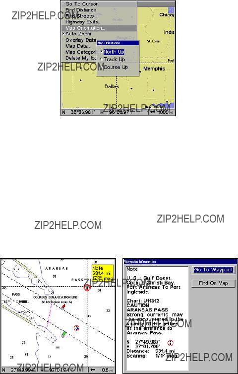
Map Orientation menu with
the North Up map orientation option selected.
NOTE
In North Up and Course Up, the present position arrow appears in the center of the map page. In Track Up, the position arrow ap- pears centered in the lower third of the page.
NauticPath??? USA Marine Charts
Your unit can display NauticPath electronic charts on MMCs. They work just like a MapCreate custom map on a MMC.
Nautical Chart Notes
NauticPath charts contain notes or chart information, represented by
NauticPath chart showing Chart Note icon selected by cursor (left). Note information screen (right).
168

To view Chart Note information:
1.Use the arrow keys to move the cursor over a Chart Note icon. When it's selected, a
2.Press WPT to display the Note Information screen.
3.To scroll through the Chart Note screen, use ??? ??? arrow keys to read the information. To return to the main page display, press EXIT repeat- edly.
Entrance to Aransas Pass on a NauticPath chart with
Port Information
NauticPath charts contain Port Services information, represented by anchor icons on the map display. These icons will appear when you are zoomed in to a
To view Port Services information:
1.Use the arrow keys to move the cursor over a Port Services icon. When it is selected, a
2.Press WPT to display the Port Services Information screen.
169

Port Servicesname box icon
NauticPath chart showing Port Services icon selected by cursor. When first highlighted, the
The Port Services information screen for a NauticPath chart contains all the service information in one window.
3. To scroll through the service information window, use ??? ??? to see the types of services available. To return to the main page display, press EXIT repeatedly.
Port Services information.
Tidal Current Information
NauticPath charts contain Tidal Current information, represented at large zoom ranges by a box icon with the letter "C." These icons will appear when you are zoomed in to a
example is displayed on the right. When you zoom in to a sufficiently small zoom range (0.8 nautical mile), the icon becomes an animated arrow showing tidal current velocity and direction for the selected tidal
170
station at the present time. At larger zoom ranges, you can select the boxed "C" icon and it becomes an animated arrow with a
To view Tidal Current information:
1.Use the arrow keys to move the cursor over a Tidal Current Station icon. When it is selected, a
2.Press WPT to display the Tidal Current Information screen.
Cursor
lines  Tidal Current Station icon in
animated mode
NauticPath chart showing Tidal Current Station icon selected by cur- sor (left). Tidal Current animated icon
Current Time Line
 Tide Tables
Current Information screen.
The Tidal Current Information screen displays daily tidal current data for this station on this date at the present time. The graph at the top of the screen is an approximate view of the flood and ebb pattern for the day, from midnight (MN), to noon (NN) to midnight (MN).
171
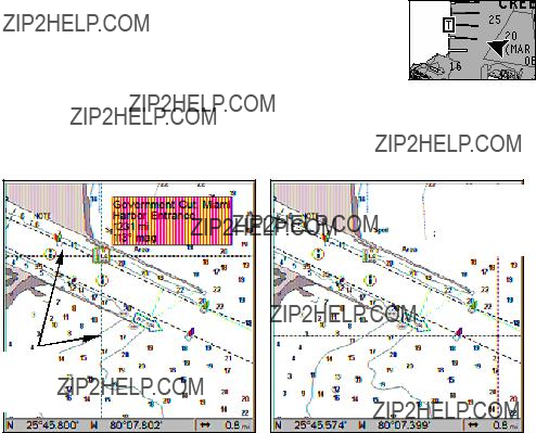
The velocity scale at the top left side of the graph changes dynamically based upon the maximum velocity of the current for that day.
Slack water, the period of little or no current, is represented by the Slack Water Line (SWL). The flood appears above the SWL and the ebb appears below the SWL. You can look up tidal current data for other dates by changing the month, day and year selection boxes.
To select another date:
1.Use ??? ??? to highlight month, day or year, then press ENT.
2.Use ??? ??? to select the desired month, day or year and press ENT. To clear the information screen, press EXIT.
Tide Information
NauticPath charts contain Tidal Information, represented at large zoom ranges by a box icon with the letter "T." These icons will appear when you are zoomed in to a
stands for a Tidal Station location. An example is displayed at right. When you zoom in to a suffi- ciently small zoom range (0.8 nautical mile), the icon becomes an animated gauge showing a rising
or falling tidal height for the selected station at the present time. At larger zoom ranges, you can select the boxed "T" icon and it becomes an animated gauge with a
Tide Station icon in ani-  mated mode
Cursor lines
NauticPath chart showing Tide Station icon selected by cursor (left). Icon animates automatically without selection at the
172

To view tide information:
1.Use the arrow keys to move the cursor over a tide station icon. When it is selected, a
2.Press WPT to display the Tide Information screen.
Current Time Line
 Height
MLLW  Scale
Scale
Line
Tide 
Table
Tide Information screen.
The Tide Information screen displays daily tidal data for this station on this date at the present time. The graph at the top of the screen is an approximate view of the tidal range pattern for the day, from midnight (MN) to noon (NN) to midnight (MN). The dotted line across the graph is the Mean Lower Low Water line (MLLW).
The height scale on the top right side of the graph changes, based upon the maximum range of the tide for that day. The MLLW line also ad- justs its position as the height scale changes.
You can look up tidal data for other dates by changing the month, day and year selection boxes. To select another date:
1.Use ??? ??? to highlight month, day or year, then press ENT.
2.Use ??? ??? to select the desired month, day or year and press ENT.
To clear the information screen, press EXIT.
Navionics??? Charts
Your unit can also display Navionics electronic charts on MMCs. Like NauticPath, Navionics charts contain tide and port service information.
NOTE:
The primary operational difference between a NauticPath chart and a Navionics chart is the way the chart data is set up for dis- play. NauticPath charts are ready for display as soon as they are
173
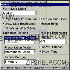
inserted into the unit. Navionics charts must be inserted into the unit, then selected as a Map Choice option in the Map Data menu.
To display a Navionics chart:
1.Install the Navionics MMC in the memory card compartment and turn on the unit. (For full card install instructions, see Sec. 2.)
2.From the Map Page, press MENU|??? to MAP DATA|ENT|??? to MAP CHOICE|ENT. Select the Map Name, then press ENT|EXIT|EXIT.
Navionics Map Choice highlighted. Press Ent to select the desired Navionics map from the Map Choice drop down box.
WARNING:
You should never format the MMC containing your Navionics chart. Formatting the MMC will permanently erase the chart from the card.
Overlay Data
On any Page display except Satellite Status, you can overlay additional GPS or navigation data on the screen with the Overlay Data command. For example, if you left your watch at home, you could display the local time on top of the map. Or, if you wanted to see details about your route and trip, you could show your bearing, course, average speed and trip distance.
The various data available from your unit are divided into categories in the Overlay Data menu. These categories include GPS Data, Naviga- tion, Trip Calculator, Time, Sonar Data and Miscellaneous Data.
You can select items from any of these categories for display, in any combination ??? the category divisions are there only to help you sort through the information.
174

Overlay Data with Navigation and Sonar Data categories expanded.
To overlay information on your screen:
1.Press MENU|??? to OVERLAY DATA|ENT.
2.If you currently have any overlay data on your screen, it will be listed here. Select (ENTER TO ADD) and press ENT. The data viewer shows information categories with "+" or
Selecting the category name and pressing ENT will show the category's contents, so you can choose items within it. An expanded category (one with a
3.Expand any categories that might contain data you want to display. Then press ??? or ??? to select a data option.
4.With the data option highlighted, press ENT to check it (turn on) and uncheck it (turn off). As you turn it on, the data will appear on top of the screen. Every Page display has a maximum number of items you can show using the Overlay Data command.
5.After the desired changes are made, press EXIT|EXIT to return to the page display.
175

From Overlay Data Shown (left) press ENT to see Data Viewer (center). Select a category and press ENT. Next, select information to show on screen and press ENT to check it and turn it on (right).
Steering arrow
Map Page shows boat cruising Puget Sound, Washington with Overlay Data turned on (left). This example shows Depth, Ground Speed and the Steering Arrow. Note that the Steering Arrow always points di- rectly to the destination you are navigating toward. In this case, the boater is on a northwest course of 275??. Since the helmsman is on course, the Steering Arrow is pointing straight ahead. If the helmsman veered off course, the arrow would show which direction to steer to get back on course. Sonar Page with Overlay Data turned on (right), showing Depth, Ground Speed and the Track the boat is following.
To remove overlaid data:
1.While on the Page that shows the item or items you want to remove, press MENU|??? to OVERLAY DATA|ENT.
2.You will see a list of the overlay data currently displayed. Select the item you want to remove from your display and press ENT|ENT to re- move the data. To remove another item, highlight the item and press
ENT|ENT.
3. When you have finished removing Overlay Data, press EXIT to return to the map page display.
176

NOTE:
You also can remove data directly from the Data Viewer menu by repeating the steps used to add overlay data. Highlight the overlay data currently displayed, then press ENT, unchecking the data op- tion, which will remove it from the display..
Overlay Data Shown menu with Date selected (left). Remove high- lighted on Data Information menu (center). Date has been removed from the Overlay Data Shown menu (right).
To move overlaid data:
You may find it useful to move or rearrange overlay data on your dis- play.
1.From one of the Map Pages, press MENU|??? to OVERLAY DATA|ENT.
2.You will see a list of the overlay data currently displayed. Select the item you want to move and press ENT|??? to MOVE|ENT.
3.The data begins to flash on your screen. Use ??? ???, ??? ??? to move the data to a new location on the screen.
4.Press EXIT|EXIT to return to the map display.
NOTE:
The Customize command and the Overlay Data command both use the same information categories. The difference between the two commands is that Customize changes only the data in digital data boxes, while Overlay Data changes the data on the floating freely on the screen but does not alter data in digital data boxes. For in- formation on customizing digital data boxes see Customize Page Displays on page 90.
177
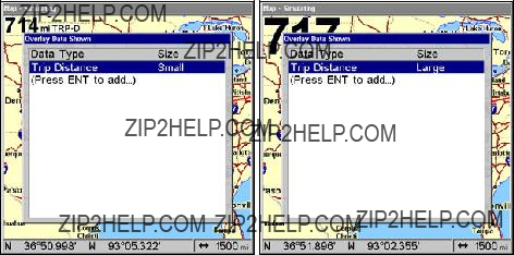
Trip Distance set to small size in the Overlay Data Shown menu (left). Trip Distance set to Large size (right).
To change displayed data font size:
1.From the Map or Sonar page, press MENU|??? to OVERLAY DATA|ENT.
2.Press ??? ??? to select the desired data type, then use ??? ??? to enlarge or reduce the size of the overlay data on the map display.
3.Press EXIT to return to the map display. The selected data type will be displayed in the new size. (To change the font size for another Data Type, repeat these steps, beginning with step 2 above.)
NOTE:
Some data types can be displayed in only one font size. If that is the case, the Data Size box will not be displayed for that data type.
Help is available for virtually all menus in this unit. By leaving a menu item or command highlighted for a few seconds, a
To set up Popup Help:
1.Press MENU|MENU|??? to SYSTEM SETUP|ENT|??? to POPUP HELP.
2.With the option highlighted, press ENT to check it (turn on) and un- check it (turn off.)
3.After the option is set, press EXIT|EXIT to return to the page display.
178

Reset Options
The Reset Options command allows you to switch unit features and functions back to factory default settings.
1. Press MENU|MENU|??? to SYSTEM SETUP|ENT|??? to RESET OPTIONS|ENT|???
to YES|ENT.
NOTE:
Reset Options does not erase any waypoints, routes, icons, plot trails or sonar logs.
Reset Options highlighted on the System Setup menu (left). Reset Op- tions confirmation message (right).
179

Screen Contrast and Brightness
To adjust Contrast:
1.Press MENU|MENU|ENT.
2.Highlight CONTRAST, then use ??? ??? to move the contrast adjustment bar. The left end of the scale is the lowest contrast level. The right end is the highest contrast level.
The Screen Menu with Contrast bar selected.
To adjust the display's brightness:
1.Press MENU|MENU|ENT.
2.Press ??? to BRIGHTNESS. Press ??? ??? to move Brightness Control bar. The left end of the scale is the lowest brightness level. The right end of the scale is the highest brightness level.
Display Mode menu.
180
To adjust the screen's display mode:
1.Press MENU|MENU|ENT.
2.Press ??? to DISPLAY MODE|ENT, which will open the Display Mode menu with three options: Normal, High Contrast and Night Viewing.
3.Select the desired mode and press ENT. Press EXIT|EXIT to return to the map display.
Set Language
This unit's menus are available in 10 languages: English, French, Ger- man, Spanish, Italian, Danish, Swedish, Russian, Dutch and Finnish. To select a different language:
1.Press MENU|MENU|??? to SYSTEM SETUP|ENT.
2.Highlight SET LANGUAGE|ENT.
3.Use ??? ??? to select the desired language and press ENT. All menus now will appear in the language you selected.
Set Local Time
Using the local time setting is useful when estimating local arrival time while navigating.
1.Make sure your unit has acquired your position, then press MENU|MENU, highlight SYSTEM SETUP and ENT.
2.Highlight SET LOCAL TIME and press ENT.
3.Local time will be highlighted, so press ENT. Use ??? ??? to change the first character, then press ??? to move the cursor to the next character. Repeat those steps until the time has been set. Press ENT.
To set the Month:
1.Make sure your unit has acquired your position, then press MENU|MENU, highlight SYSTEM SETUP and ENT.
2.Highlight SET LOCAL TIME and press ENT.
3.Select MONTH and ENT. Use ??? ??? to select the desired month and press
ENT.
To set the Day:
1.Make sure your unit has acquired your position, then press MENU|MENU, highlight SYSTEM SETUP and ENT.
2.Highlight SET LOCAL TIME and press ENT.
3.Highlight DAY and press ENT. Use ??? ??? to select the desired day and press ENT.
181
To set the Year:
1.Make sure your unit has acquired your position, then press MENU|MENU, highlight SYSTEM SETUP and ENT.
2.Highlight SET LOCAL TIME and press ENT.
3.Select YEAR and press ENT. Use ??? ??? to select the year and press ENT.
To select Time Format:
1.Make sure your unit has acquired your position, then press MENU|MENU, highlight SYSTEM SETUP and ENT.
2.Highlight SET LOCAL TIME and press ENT.
3.Select the desired format, 12 Hour or 24 Hour, and press ENT.
To select a Date Format:
1.Make sure your unit has acquired your position, then press MENU|MENU, highlight SYSTEM SETUP and ENT.
2.Highlight SET LOCAL TIME and press ENT.
3.Select the desired Date Format, Month/Day/Year, Day/Month/Year or Year/Month/Day and press ENT.
To Configure DST:
Configure DST allows your unit to automatically adjust to Daylight Saving Time. Select the country with DST rules that match your region or simply accept the default.
1.Make sure your unit has acquired your position, then press MENU|MENU, highlight SYSTEM SETUP and ENT.
2.Select SET LOCAL TIME and press ENT.
3.Highlight the CONFIGURE DST button and press ENT. From the Country menu, select the country with DST rules that match your region.
4.Press EXIT repeatedly to return to the map display.
Show WAAS Alarm
When the signal is available, your unit will automatically use WAAS to boost the accuracy of the position fix. When the WAAS signal is lost or acquired, an alarm message appears. Since the U.S. government is still developing the WAAS system, its not unusual for a GPS/WAAS re- ceiver to frequently lose and reacquire its lock on a WAAS satellite. That can result in the alarm repeatedly going on and off. You have the option of turning off the WAAS Acquired/Lost alarm without affecting how the unit uses WAAS.
182
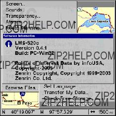
To turn on/off the WAAS Alarm:
1.Press MENU|MENU|??? to GPS SETUP|ENT|??? to SHOW WAAS ALARM.
2.With the option highlighted, press ENT to check it (turn on) or un- check it (turn off) the WAAS Alarm.
3.Press EXIT|EXIT to return to the map display.
To Require WAAS:
1.Press MENU|MENU|??? to GPS SETUP|ENT|??? to REQUIRE WAAS.
2.With the option highlighted, press ENT to check it (turn on) or un- check it (turn off).
3.Press EXIT|EXIT to return to the map display.
Software Version Information
From time to time, Lowrance updates the operating system software in some of its products. These software upgrades are usually offered to customers as free downloads from our web site, www.lowrance.com. These upgrades make the unit perform better and/or introduce a new feature or function. You can find out what software version is running in your unit by using the Software Information command.
The Software Information screen.
To access Software Information:
1.Press MENU|MENU, highlight SYSTEM SETUP and press ENT.
2.Select SOFTWARE INFO and press ENT. Software information will be dis- played on the screen.
3.Press EXIT repeatedly to return to the map display.
183
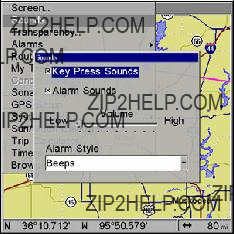
Sounds and Alarm Sound Styles
Sounds triggered by key strokes and alarms can be turned off or ad- justed to a desired level.
The Sounds menu.
To set Key Press Sounds:
1.Press MENU|MENU, select SOUNDS and press ENT.
2.Highlight KEY PRESS SOUNDS and press ENT to check it (turn on) or un- check it (turn off.
3.Press EXIT|EXIT to return to the map display.
To set Alarm Sounds:
1.Press MENU|MENU, select SOUNDS and press ENT.
2.Highlight ALARM SOUNDS and press ENT to check it (turn on) or uncheck it (turn off).
3.Press EXIT|EXIT to return to map page display.
To set Volume:
1.Press MENU|MENU, select SOUNDS and press ENT.
2.Highlight VOLUME and use ??? ??? to move the Volume control bar. The left end of the scale is low volume. The right end of the scale is high vol- ume.
3.Press EXIT|EXIT to return to map display.
To set Alarm Style:
1.Press MENU|MENU, select SOUNDS and press ENT.
2.Highlight ALARM STYLE and press ENT.
3.Use ??? ??? to select the desired style and press ENT.
4.Press EXIT|EXIT to return to the map display.
184
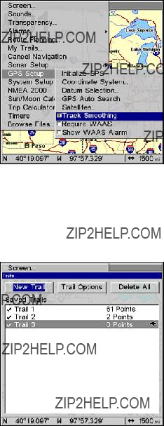
Track Smoothing
This is a factory setting on the GPS Setup menu that should always be left on. When stopped or traveling at slow speeds (such as walking or trolling), Track Smoothing prevents wandering of trails, the steering arrow, compass rose and a map in
Track Smoothing highlighted on the GPS Setup menu.
Trail Options
There are several options you can use with trails. Some affect all trails, other options can be applied to a particular trail. You can change the way trails are updated, display or hide trails, create a new trail, delete a trail and edit a trail's name, color, pattern and visibility.
The Trails Menu.
185
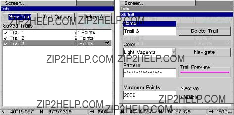
To create a New Trail:
1.Press MENU|MENU, highlight MY TRAILS and press ENT.
2.Highlight NEW TRAIL and press ENT. The Edit Trail menu will appear, allowing you to Edit the trails name, color, pattern, maximum points, trail status (active or inactive) and trail visibility. You can also navi- gate the trail or delete the trail.
New Trail selected on the Trails menu (left). Edit Trails menu (right).
To Delete all Trails
1.Press MENU|MENU, select MY TRAILS and press ENT.
2.Highlight DELETE ALL and press ENT. The following Warning will ap- pear: Delete All Trails?
3.Select YES and press ENT. You will be returned to the Trails screen, where all trails have been deleted.
4.Press EXIT repeatedly to return to the map display.
Update Trail Option
The Update Trail menu allows you to change the way trail updates oc- cur. There are three options: Auto, Time and Distance.
In automatic mode, the unit does not update the plot trail while you are traveling in a straight line. When you deviate from a straight line, the unit places a plot point onto the trail. This conserves plot trail points. If a plot trail uses all of the available points allotted to it, the beginning points are deleted and replaced by points at the end of the trail.
Selecting Time as the method for updating a trail will automatically place trail points at a duration of your choosing. You can set the unit to place trail points placed at any duration between 1 second to 9999 sec- onds. The default setting is 3 seconds. Updating a trail by Distance will place trail points when you move a distance of your choosing.
186
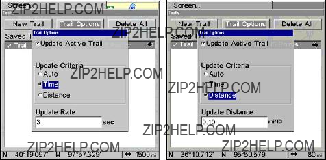
You can have trail points placed at any distance between 0.01 mile/nm/km to 9.99 mile/nm/km. The default setting is 0.10 mi.
WARNING:
If you uncheck the Update Trail option, automatic trail creation and recording will be turned off. You must turn it back on to record trails. The default setting is on.
To select a Trail Update Option:
1.Press MENU|MENU, select MY TRAILS and press ENT.
2.Highlight the TRAIL OPTIONS button and press ENT. The Trail Options menu will appear with three update criteria: Auto, Time and Distance.
NOTE:
The Update Active Trail checkbox should be checked (turned on). If it is unchecked (turned off), your trails will not be updated. To turn it on, highlight UPDATE ACTIVE TRAIL and press ENT.
3.Highlight the desired method for updating trails and press ENT. If you choose Time or Distance as your update criteria, you can input the desired update rate (Time) or desired Update Distance (Distance) in the dialog box that appears at the bottom of the menu.
4.To input your Update Rate or Update Distance, highlight Update Rate or Update Distance and press ENT. Use ??? ??? , ??? ??? to input the desired setting and press ENT.
5.Press EXIT repeatedly to return to the map display.
Time set as the update criteria (left). Notice the Update Rate dialog box at the bottom of the menu. Distance is set as the update criteria (right). The Update Distance dialog is at the bottom of the menu.
187
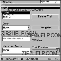
To delete a Trail:
1.Press MENU|MENU, select MY TRAILS and press ENT.
2.Select the desired trail from the Saved Trails list and press ENT. The Edit Trail menu will appear.
3.Highlight DELETE TRAIL and press ENT. The following message will ap- pear: Delete this trail? Select YES and press ENT.
4.Press EXIT repeatedly to return to the map display.
Edit Trail menu.
Trail Visible/Invisible and Other Trail Options
The name, maximum number of points in the trail, activity, and visibil- ity are all changed on the Edit Trail menu screen. The Active setting determines whether or not the unit is recording new points for a par- ticular trail.
On the Edit Trail menu, press ??? ??? to highlight the section you wish to change, then press ENT. Make your changes, then press EXIT to close the menu. Related trail functions are discussed in further detail under the Trails topic in Sec. 7, Advanced GPS Operations.
Transparency
Use the transparency menu to adjust the transparency of menu win- dows. A high transparency allows you to continue monitoring the screen's display while adjusting feature settings, though the text of the menus may fade until it is unreadable. A low transparency will usually make menu text easier to read, at the cost of watching your display.
Experiment with this feature until you find the right level of transpar- ency for your eyes.
188

Transparency selected on main menu.
To adjust Transparency level:
1.Press MENU|MENU|??? to TRANSPARENCY|ENT. The TRANSPARENCY slider
bar appears.
2.Use ??? ??? to move the bar. Move the bar to the bottom of the scale to eliminate transparency. Moving the bar to the top of the scale will pro- vide the greatest level of transparency.
3.Press EXIT to return to the map display.
Units of Measure
This menu sets the speed and distance (statute or nautical miles, me- ters), depth (feet, fathoms, or meters), temperature (degrees Fahren- heit or Celsius) and heading (true or magnetic) units.
To change Units of Measure:
To set Speed/Distance:
1.Press MENU|MENU, select System Setup and press ENT. UNITS OF MEAS- URE will be highlighted, so press ENT.
2.Speed/Distance will be highlighted. Press ENT.
3.Use ??? ??? to select one of the following options: Statute, Nautical or Metric. Press ENT.
4.Press EXIT repeatedly to return to the sonar display.
189
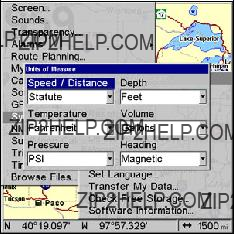
Units of Measure Menu.
To set Temperature units:
1.Press MENU|MENU, select System Setup and press ENT. UNITS OF MEAS- URE will be highlighted, so press ENT.
2.Highlight TEMPERATURE and press ENT.
3.Use ??? ??? to select one of the following options: Fahrenheit, Celsius or Kelvin. Press ENT.
4.Press EXIT repeatedly to return to the sonar display.
To set Pressure units:
1.Press MENU|MENU, select System Setup and press ENT. UNITS OF MEAS- URE will be highlighted, so press ENT.
2.Highlight PRESSURE and press ENT.
3.Use ??? ??? to select one of the following options: Millibars, Bars, PSI, Hectopascals or Kilopascals. Press ENT.
4.Press EXIT repeatedly to return to the sonar display.
To set Depth units:
1.Press MENU|MENU, select System Setup and press ENT. UNITS OF MEAS- URE will be highlighted, so press ENT.
2.Highlight DEPTH and press ENT.
3.Use ??? ??? to select one of the following options: Feet, Fathoms or Me- ters. Press ENT.
4.Press EXIT repeatedly to return to the sonar display.
190
To set Volume units:
1.Press MENU|MENU, select System Setup and press ENT. UNITS OF MEAS- URE will be highlighted, so press ENT.
2.Highlight VOLUME and press ENT.
3.Use ??? ??? to select one of the following options: Gallons or Liters. Press
ENT.
4.Press EXIT repeatedly to return to the sonar display.
To set Heading units:
1.Press MENU|MENU, select System Setup and press ENT. UNITS OF MEAS- URE will be highlighted, so press ENT.
2.Highlight HEADING and press ENT.
3.Use ??? ??? to select one of the following options: True or Magnetic. Press ENT.
4.Press EXIT repeatedly to return to the sonar display.
The Units of Measure Menu.
To set Speed/Distance Unit of Measure: Press ??? or ??? to change the Speed/Distance, then press ENT. After the option is set, press EXIT|EXIT|EXIT to return to the page display.
To set Heading: Press ??? or ??? to change the heading type, then press ENT. After the option is set, press EXIT|EXIT|EXIT to return to the page display.
191
Notes
192
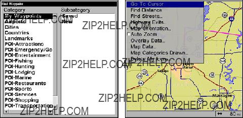
Section 9: Searching
NOTE:
The background map loaded in your unit's permanent memory lets you search for some land features, including cities and lakes. For a full set of searchable land features, including landmarks, streets, addresses, highway exits and Points of Interest, you must load your own
This unit's varied search functions all begin with either the Find Way- point menu or the Map Page menu. Press WPT and the Find Waypoint menu appears for waypoints and Points of Interest (POI). From the Map Page, press MENU and the Map Page menu appears for streets and highway exits.
Find Waypoint menu (left). Map Page menu (right).
NOTE:
You can search for items after the unit has acquired a position, or while using the unit in simulator mode. Distance and bearing to the selected item will be calculated from the unit's current position, or the last known position if operating in simulator mode or with- out a position determined). You can look up items by name or search for items nearest to you.
193

Find Streets
1.From a Map Page, press MENU|??? to FIND STREETS|ENT.
2.Press ENT to search in the Street field.
3.To enter a street name, press ??? to STREET|ENT. There are two options: A. You can spell out the name in the top selection box. Press ??? or ??? to change the first letter, then press ??? to move the cursor to the next let- ter and repeat until the name is correct, then press ENT|ENT.
B. Jump down to the lower selection list by pressing ENT, then press ??? or ??? to select a street name from the list, then press ENT. The street name you selected is now in the street field.
Finds Streets menu (left). Find Street by Name menu (right).
4. To enter a city name, press ??? to CITY|ENT. You will be asked if you want to find streets only within a particular city. This option is de- signed so you can limit an address search to a single city if necessary (see the following note).
If you select yes, there are two options: A. You can spell out the city name in the top selection box. Press ??? or ??? to change the first letter, then press ??? to move the cursor to the next letter and repeat until the name is cor- rect, then press ENT|ENT. B. Jump down to the lower selection list by pressing ENT, then press ??? or ??? to select a city name from the list, then press ENT. The city name you selected is now in the city field.
NOTE:
We recommend that you do not enter a city name unless the list you are given is too large when searching without it. This unit can actually search quicker when you don???t enter a city.
194
Find By Name menu with list of cities.
Find Any Item Selected by Map Cursor
With a POI or map feature selected by the cursor, press WPT. To return to the previous page, press EXIT.
A POI selected by the cursor (left). POI information screen (right).
NOTE:
Since the Go To Waypoint command is highlighted, you can navi- gate to the selected POI by pressing ENT|EXIT while in the POI Waypoint Information screen.
Find Interstate Highway Exits
1. From the Map Page, press MENU|??? to HIGHWAY EXITS|ENT, which calls up the Find Exit menu.
195

The Find Exit menu.
2. First, select a highway name by pressing ENT, which calls up the Find By Name menu. There are two highway search options: A. You can spell out the highway name in the top selection box. Press ??? or ??? to change the first letter, then press ??? to move the cursor to the next let- ter and repeat until the name is correct, then press ENT|ENT. B. Jump down to the lower selection list by pressing ENT, then press ??? or ??? to select a highway from the list, then press ENT.
Find By Name menu.
3. Once you have selected a highway name you can then select an exit. Press ??? to switch to the Exit List, then press ??? or ??? until you highlight the exit, then press ENT.
196
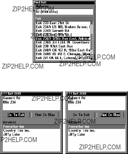
Find Exit menu with an exit selected in the Exit List.
4. In the Exit Information screen you have two choices. A. Press ENT to navigate or "go to" the exit. B. Press ???|ENT to find the exit on the map.
Go To Exit highlighted (left). Find On Map selected (right).
Tip:
You can also look up some additional information on the Exit Ser- vices located near this exit. Press ??? to SERVICES|press ??? ??? to select
Service Name|ENT.
197
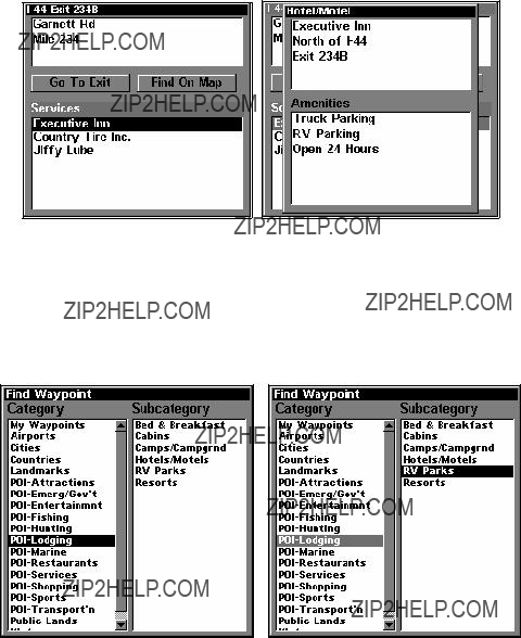
Exit Information screen (left). General location and amenities information (right).
Find Map Places or Points of Interest (POI)
1. Press WPT, press ??? or ??? to select a map place or POI category, then press ENT. (To narrow your search, press ??? then press ??? or ??? to select a subcategory before pressing ENT.) You will be given two options; Search By Name or By Nearest.
Find Waypoint menu with Lodging POI category selected (left) and with the RV Parks subcategory selected (right).
2. To search by the nearest POI: press ???|ENT. The find by nearest menu will show a calculating screen, then a list of the nearest POI's will appear. Press ??? ??? to the selected POI and press ENT to call up the POI's Waypoint Information screen.
198

Find by Nearest option, left, Calculating screen, center, POI list, right.
3. To search by the name of a POI: press ENT. There are two options: A. You can spell out the POI in the top selection box. Press ??? or ??? to change the first letter, then press ??? to move the cursor to the next let- ter and repeat until the name is correct, then press ENT|ENT. B. Jump down to the lower selection list by pressing ENT, then press ??? or ??? to select a POI from the list, then press ENT to call up the POI's Waypoint Information screen.
Find by Name option, left, Find by Name menu, right.
4. When the POI's Waypoint Information screen is displayed, you can choose to Go To the POI waypoint by pressing ENT or find it on the map by pressing???|ENT.
199

Go To Waypoint highlighted (left). Find on Map selected (right).
Find Streets or Intersections
Find a Street
1.From the Map Page, press MENU|??? to FIND STREETS|ENT and the Find Streets Menu appears.
2.You must first fill in a street name in the First Street dialog box. Press ENT to display the Find By Name menu. There are two options:
A. You can spell out the street in the top selection box. Press ??? or ??? to change the first letter, then press ??? to move the cursor to the next let- ter and repeat until the name is correct, then press ENT|ENT. B. Or you can jump down to the lower box and pick a street from the list. Press ENT, then press ??? or ??? to select a street from the list and press ENT.
Find Streets menu (left). When finding a street by name (right), spell out the name in the top box or select it from the list in the lower box.
3. The Find Streets menu reappears with the street you're searching for in the First Street box. (In this example, it's 80th Street.) To search
200
for that street, press ??? to FIND FIRST STREET|ENT. A message appears ask- ing you to wait while the unit finds the street. When the Streets Found list appears, press ??? or ??? to select the street you are searching for and press ENT.
Find Streets menu with the Find First street highlighted (left). Streets Found list (right).
4. The Map Page appears, with the cursor pointing to the found street.
If you want to navigate to the found street at the cursor location, just press MENU|ENT|EXIT.
Map Page showing results of a street search.
The cursor points to the located street.
Find an Intersection
You must enter one street in the First Street dialog box and enter the next street in the Second Street dialog box.
1. From the Map Page, press MENU|??? to FIND STREETS|ENT and the Find Streets Menu appears.
201
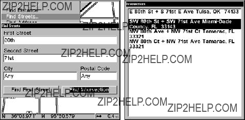
2.You must fill in a street name in the First Street dialog box. Press ENT to display the Find By Name menu. There are two options: A. You can spell out the street in the top selection box. Press ??? or ??? to change the first letter, then press ??? to move the cursor to the next letter and repeat until the name is correct, then press ENT|ENT. B. Or you can jump down to the lower box and pick a street from the list. Press ENT, then press ??? or ??? to select a street from the list and press ENT.
3.The Find Streets menu reappears with the street you're searching for in the First Street box. (In this example, it's 80th Street.)
4.Now fill in the second street. Press ??? to SECOND STREET|ENT and the Find By Name menu appears again. Just like before, there are two op- tions: A. You can spell out the second street in the top selection box. Press ??? or ??? to change the first letter, then press ??? to move the cursor to the next letter and repeat until the name is correct, then press ENT|ENT. B. You can also jump down to the lower box and pick the sec- ond street from the selection list. Press ENT, then press ??? or ??? to select a street from the list and press ENT.
5.The Find Streets menu reappears with the first and second street dialog boxes filled in. In this example, we selected 71st Avenue as our second street. You could now use similar techniques to select a city or Zip code, but your search will probably be faster if you leave those boxes blank. (You can specify a city and/or zip code when the search result list is too long.)
Find Intersection command highlighted (left). Intersections Found list (right).
6. To search for the intersection of the two streets, press ???|??? to FIND INTERSECTION|ENT. A message appears asking you to wait while the unit finds the intersection. When the Intersections Found list appears, press
202

??? or ??? to select the intersection you are searching for and press ENT. (In our example, we selected the intersection of SW 80th Street and SW 71st Avenue in Miami, Fla.)
7. The Map Page appears, with the cursor pointing to the found intersec- tion. The intersection in our example is shown in the following figure.
Map Page showing results of an intersection search.
The cursor points to the located intersection.
If you want to navigate to the found intersection, just press
MENU|ENT|EXIT.
Find Waypoints
1.Press WPT|ENT.
2.If searching for the waypoint By Name, press ENT. If searching for the Nearest waypoint, press ??? to NEAREST|ENT. (To search by name, jump to step 5.)
Find By Nearest command (left). Find by Name command (right).
203
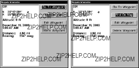
3.If you're looking for nearest, the unit says it is calculating, then a list of waypoints appears. The closest waypoint is highlighted at the top of the list. The waypoint furthest from you is at the bottom of the list.
4.To see location information on the closest (highlighted) waypoint, press ENT and the Waypoint screen appears. (If you wanted to, you
could select another waypoint from the list with the ??? or ??? keys.)
A.To navigate to the waypoint, press ENT. (The Go To Waypoint command is already highlighted.) The unit will show navigation in- formation to the waypoint.
B.To find the waypoint, press ??? to FIND ON MAP|ENT. The Map Page appears with the cursor highlighting the found waypoint.
Waypoint Information screens with Go To Waypoint selected (left) and Find on Map selected (right).
To return to the previous page, press EXIT repeatedly.
5. If you're looking by name, there are two options: A. You can spell out the name in the top selection box. Press ??? or ??? to change the first letter, then press ??? to move the cursor to the next letter and repeat until the name is correct, then press ENT|ENT. B. Or you can jump down to the lower selection list by pressing ENT, then press ??? or ??? to select a way- point from the list, then press ENT. The waypoint screen appears.
204

Find By Name menu (left). Waypoint Information screen (center). The found waypoint is highlighted by the cursor on the Map Page (right).
A.To navigate to the waypoint, press ENT. (Go To Waypoint com- mand is already highlighted.) The unit will show navigation infor- mation to the waypoint.
B.To find the waypoint, press ??? to FIND ON MAP|ENT. The Map Page appears with the cursor highlighting the found waypoint.
205
Notes
206

Section 10: NMEA 2000
Device Configuration
NMEA 2000 Menu
The NMEA 2000 menu on your display unit's main menu allows you to configure, calibrate and monitor devices on a NMEA 2000 network. The NMEA 2000 menu provides access to the Bus Setup, Fuel Management and NMEA 2000 Alarms. You also can turn on/off Waypoint Sharing and Backlight Synchronization from the NMEA 2000 menu.
Bus Setup
Selecting Bus Setup from the NMEA 2000 menu gives you access to the Bus Configuration menu and the NMEA Diagnostics and Ethernet Di- agnostics pages. The Bus Configuration menu allows you to choose an
Bus Setup highlighted on the NMEA 2000 menu.
Bus Configuration menu (left). NMEA Diagnostics page (center). Ethernet Diagnostics (right).
207
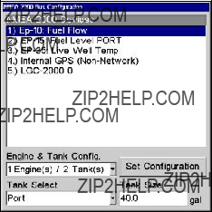
The NMEA Diagnostics page displays information about the perform- ance of the network bus, keeping you updated on bus status, mode, er- rors and bus traffic. The Ethernet Diagnostics page keeps you updated on the performance of an Ethernet connection (if applicable) supplying information ranging from IP Address to upload and download rates (bytes per second). To refresh either Diagnostics page, highlight the PING ALL DEVICES button at the bottom of the page and press ENT.
The network devices list is located in the top half of the Bus Configura- tion menu. You can configure, calibrate and set alarms for devices ac- cessed from the Bus Configuration menu network devices list.
The
NOTE:
If you have not used the
Bus Configuration menu with list of network devices.
Engine & Tank Configuration
The
208
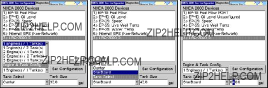
Tank Select
The Tank Select menu allows you to choose from up to three tanks (Port, Center and Starboard), depending on the
Tank Size
The Tank Size menu allows you to input the size of a selected tank in gallons. After selecting the desired tank from the Tank Select menu, you are ready to enter the tank's size.
Set Configuration button
The Set Configuration button is used to finalize
Setting
1.Press MENU| MENU, use ??? ??? to highlight NMEA 2000 and press ENT.
2.The NMEA 2000 menu will appear with five options: Bus Setup, Fuel Management, NMEA 2000 Alarms, Waypoint Sharing and Back- light Synchronization. Choose BUS SETUP and press ENT.
3.Select ENGINE & TANK CONFIG and press ENT, which will open the Engine & Tank Configuration menu with the following configuration options: 1 Engine/1 Tank, 1 Engine/2 Tanks, 2 Engines/1 Tank, 2 Engines/2 Tanks, 3 Engines/1 Tank, 3 Engine/3 Tanks and Unconfigured Bus.
1 Engine/1Tank highlighted on Engine and Tank Configuration menu (left). Starboard highlighted on Tank Select menu (center). Tank Size set to 40 gallons (right).
4.Choose the configuration that matches the number of engines and tanks on your vessel and press ENT.
5.Highlight TANK SELECT and press ENT, which will open the Tank Select menu.
6.Select the tank you want to set up and press ENT. Press ??? to high- light the Tank Size dialog box and press ENT.
209
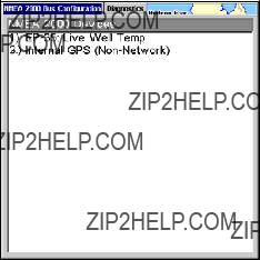
7.Use ??? ???, ??? ??? to input the capacity (gallons) of the tank you chose from the Tank Select menu and press ENT.
8.Repeat Steps
9.When all tanks have been configured, press the SET CONFIGURATION but- ton. The following confirmation message will appear: Are you sure you wish to change the bus configuration? Choose YES and press ENT, Press
EXIT to get back to the main display.
Device Configuration Menu
When a device is selected from the network devices list on the Bus Con- figuration menu, its Device Configuration menu will appear. Device configuration menus vary among devices. Available functions on device configuration menus allow you to change device names, tank sizes, fluid types and provide access to the Advanced Options menu. We will cover configuration and calibration later in this section.
Device Information and Device Data
The Device information panel, located to the left of the Device Configu- ration menu, displays information on the selected device that includes, software version, model, address, serial number, instance and current status.
If you do not have an
Device Data is shown in the Device Data window at the bottom of the device configuration menu. The information displayed in the Device Data window will vary among devices. If, for example, you are viewing the device configuration menu for an
210
The Device Data for an
NOTE:
If, as in the graphic above, you do not have a Suzuki Engine Inter- face,
Fuel Management Menu
The Fuel Management menu gives you access to the following options: Tank Location, Fuel Added, Add Fuel, Fill Tank, Engine Select, Reset Calibration, Reset Trip and Reset Seasonal. Those options allow you to configure, calibrate, reset calibration, reset trip fuel and reset seasonal fuel for select NMEA 2000 devices. We will cover configuration and cali- bration procedures later in this section.
Fuel Management highlighted on the NMEA 2000 menu (left). Fuel Management menu (right).
Tank Location
If you chose an
Fuel Added
Used in tandem with the Add Fuel command, the Fuel Added dialog box allows you to input the amount of fuel added to the tank, when an amount of fuel is added that does not fill up the tank.
211
Add Fuel
After entering the amount of fuel added to a tank in the Fuel Added dialog, the Add Fuel command finalizes the entry of the data. Like the Fuel Added dialog, the Add Fuel command will only be used when an amount of fuel is added that does not fill up the tank.
Fill Tank
You will use the Fill Tank command when calibrating a fuel flow and when filling up the tank without calibration.
Adding Fuel to Tank
Tank Location, Fuel Added and Add Fuel commands work together to keep NMEA 2000 fuel data consistent with the actual amount of fuel added to the fuel tank(s).
1.Press MENU|MENU, select NMEA 2000 and press ENT.
2.The NMEA 2000 menu will appear with five options: Bus Setup, Fuel Management, NMEA 2000 Alarms, Waypoint Sharing and Back- light Synchronization. Select FUEL MANAGEMENT and press ENT.
3.Highlight TANK LOCATION and press ENT. The Tank Location menu will appear with up to three options: Port, Center and Starboard.
4.Select the tank you added fuel to and press ENT.
5.Follow the steps below that apply to your tank.
If you filled up the tank:
A. Press the FILL TANK button and press ENT. The following message will appear: Are you sure you wish to Fill Tank? Press ENT. Another mes- sage will appear: Do you wish to
If you did not fill up the tank:
B. Highlight FUEL ADDED and press ENT to access the FUEL ADDED dialog box. Use ??? ??? , ??? ??? to input the amount of fuel added to the tank and press ENT. Select the ADD FUEL button and press ENT. The following mes- sage will appear: Are you sure you wish to Add Fuel? Highlight YES and press ENT.
6. Press EXIT repeatedly to get back to the main display.
Engine Operations
The lower half of the Fuel Management menu contains the following Engine Operation functions: Engine Select, Reset Calibration, Reset Trip and Reset Seasonal.
Engine Select
Engine Select allows you to choose the desired engine when resetting calibration, resetting trip fuel and resetting seasonal fuel.
212
To Reset Calibration:
Choosing the Reset Calibration command will switch fuel flow calibra- tion settings back to factory defaults.
1.Press MENU|MENU, select NMEA 2000 and press ENT.
2.Highlight FUEL MANAGEMENT and press ENT. The Fuel Management menu will appear.
3.Highlight to ENGINE SELECT and press ENT. Select the desired engine ??? the engine attached to the desired fuel flow ??? and press ENT.
4.Highlight RESET CALIBRATION and press ENT. The following confirma- tion message will appear: Are you sure you wish to Reset Calibration?
Select YES and press ENT. Calibration settings for the selected fuel have been returned to factory defaults.
To Reset Trip:
The Reset Trip function allows you to reset to zero the running total of fuel used on a particular trip.
1.Press MENU|MENU, select NMEA 2000 and press ENT.
2.Highlight FUEL MANAGEMENT and press ENT. The Fuel Management menu will appear.
3.Select RESET TRIP and press ENT. The following confirmation message will appear: Are you sure you wish to Reset Trip? Highlight YES and press ENT. The Trip Fuel Used figure has been reset to zero.
To Reset Seasonal:
Your unit can track fuel usage not only for trips, but also for entire sea- sons. The reset seasonal command allows you to reset to zero the run- ning total of fuel used during a season.
1.1. Press MENU|MENU, select NMEA 2000 and press ENT.
2.Highlight FUEL MANAGEMENT and press ENT. The Fuel Management menu will appear.
3.Select RESET SEASONAL and press ENT. The following confirmation mes- sage will appear: Are you sure you wish to Reset Seasonal?
Highlight YES and press ENT. The Seasonal Fuel Used figure has been reset to zero.
NMEA 2000 Alarms
The NMEA 2000 Alarms menu allows you to set Full and Empty fuel alarms for the
213
The second tab at the top of the NMEA 2000 Alarms page is the Alarm Status Tab. When an alarm has been set for a device, the alarm and its current status will be shown on the Alarm Status window. To view the Alarm Status window, highlight the Alarm Status tab and press ENT.
To set NMEA 2000 Alarm:
1.Press MENU|MENU, select NMEA 2000 and press ENT.
2.Highlight NMEA 2000 ALARMS and press ENT.
3.Highlight FLUID LEVEL DEVICE and press ENT. Use ??? ??? to select the de- vice you want to set an alarm for and press ENT.
4.Highlight the ENABLED box next to the desired alarm (Full Alarm or Empty Alarm) and press ENT to turn on the alarm.
5.To set the alarm percentage, press ??? to highlight PERCENT and press
ENT.
6.Use ??? ???, ??? ??? to input the desired percentage and press ENT. Repeat Steps
7.Highlight SET CONFIGURATION and press ENT to finalize alarm settings. Press EXIT repeatedly to get back to the main display.
NOTE:
To turn off (uncheck) an alarm, highlight its ENABLED BOX and press
ENTER.
Waypoint Sharing
Waypoint Sharing allows you to share a waypoint from one display unit with display units across the network.
To turn on/off Waypoint Sharing:
1.Press MENU|MENU, select NMEA 2000 and press ENT.
2.Highlight WAYPOINT SHARING and press ENT which will turn on/off way- point sharing.
3.Press EXIT repeatedly to get return to the main display.
Backlight Synchronization
The Backlight Synchronization command will keep all display unit backlight levels consistent across the NMEA 2000 network. So, if you set the backlight level to 75% on one display unit, all other units on the network will automatically switch to the same setting.
214
To turn on/off Backlight Synchronization:
1.Press MENU|MENU, select NMEA 2000 and press ENT.
2.Highlight BACKLIGHT SYNCHRONIZATION and press ENT, which will turn on/off Backlight Synchronization.
3.Press EXIT repeatedly to get back to the main display.
Configuring EP Sensors
All configurable devices are configured through their Device Configura- tion menus, which may be accessed through the network devices list on the Bus Configuration menu.
To input Device Name:
1.Press MENU|MENU, use ??? ??? to select NMEA 2000 and press ENT. The NMEA 2000 menu will appear with five options: Bus Setup, Fuel Man- agement, NMEA 2000 Alarms, Waypoint Sharing and Backlight Syn- chronization.
2.Highlight BUS SETUP and press ENT, which will open the Bus Configu- ration menu. A list of network devices will be at the top of the page.
3.Select the temp sensor you want to rename and press ENT. The De- vice Configuration menu will appear with the Device Name dialog box highlighted.
4.Press ENT and use ??? ???, ??? ??? to input the desired name for the temp sensor. Press ENT. Press EXIT repeatedly to get back to the main dis- play.
To select Temp Type:
1.Press MENU|MENU, use ??? ??? to select NMEA 2000 and press ENT. The NMEA 2000 menu will appear with five options: Bus Setup, Fuel Man- agement, NMEA 2000 Alarms, Waypoint Sharing and Backlight Syn- chronization.
2.Highlight BUS SETUP and press ENT, which will open the Bus Configu- ration menu. A list of network devices will be at the top of the page.
3.Select the desired temp sensor and press ENT. The Device Configura- tion menu will appear.
4.Highlight TEMP TYPE and press ENT. The following list of Temp Types will appear: Water, Outside, Inside, Engine Room, Cabin, Live Well, Bait Well, Refigeration, Heating System and Unknown.
5.Highlight the desired Temp Type and press ENT. The following con- firmation message will appear: Are you sure you wish to change this device's configuration?
6.Highlight YES and press ENT. Press EXIT repeatedly to get back to the main display.
215
Advanced Options menu
The Temp sensor Advanced Options menu contains two categories: In- stance and Restore Defaults.
Instance
The Instance command is intended for use only by experienced NMEA 2000 network technicians. Instance allows network technicians to re- solve certain electronic probe conflicts. This is most likely to occur if the network includes
You should never need this command if you are connecting your unit to a network with similar display units and/or a series of electronic probes.
Restore Defaults
The Restore Defaults command allows you to reset an individual
To restore default settings:
1.Press MENU| MENU, use ??? ??? to select NMEA 2000 and press ENT. The NMEA 2000 menu will appear with five options: Bus Setup, Fuel Man- agement, NMEA 2000 Alarms, Waypoint Sharing and Backlight Syn- chronization.
2.Highlight BUS SETUP and press ENT, which will open the Bus Configu- ration menu. A list of network devices will be at the top of the page.
3.Select the desired temp sensor and press ENT. The Device Configura- tion menu will appear.
4.Highlight ADVANCED OPTIONS and press ENT.
5.Select RESTORE DEFAULTS and press ENT. The following message will appear: Are you sure you wish to change this device's configuration?
6.Highlight YES and press ENT. Press EXIT repeatedly to get back to the main display.
To input Device Name:
1. Press MENU| MENU, use ??? ??? to select NMEA 2000 and press ENT. The NMEA 2000 menu will appear with five options: Bus Setup, Fuel Man- agement, NMEA 2000 Alarms, Waypoint Sharing and Backlight Syn- chronization.
216
2.Highlight BUS SETUP and press ENT, which will open the Bus Configu- ration menu. A list of network devices will be at the top of the page.
3.Select the fuel flow you want to rename and press ENT. The Device Configuration menu will appear with the Device Name dialog box high- lighted.
4.Press ENTER and use ??? ???, ??? ??? to input the desired name for the fuel flow. Press ENT. Press EXIT repeatedly to get back to the main display.
To select a Location:
1.Press MENU| MENU, use ??? ??? to select NMEA 2000 and press ENT. The NMEA 2000 menu will appear with five options: Bus Setup, Fuel Man- agement, NMEA 2000 Alarms, Waypoint Sharing and Backlight Syn- chronization.
2.Highlight BUS SETUP and press ENT, which will open the Bus Configu- ration menu. A list of network devices will be at the top of the page.
3.Select the desired fuel flow and press ENT. The Device Configuration menu will appear.
4.Select LOCATION and press ENT, which will open the Location menu with following options: Port, Center, Starboard and Unknown.
5.Highlight the desired location and press ENT. The following message will appear: Are you sure you wish to change this device's configuration?
5. Select YES and press ENT. Press EXIT repeatedly to get back to the main display.
Advanced Options menu
The Fuel Flow sensor Advanced Options menu contains two categories: Instance and Restore Defaults.
Instance
The Instance command is intended for use only by experienced NMEA 2000 network technicians. Instance allows network technicians to re- solve certain electronic probe conflicts. This is most likely to occur if the network includes
If you want to use your unit in a network including one of these digital gauges, you may need to consult customer service.
You should never need this command if you are connecting your unit to a network with similar display units and/or a series of electronic probes.
Restore Defaults
The Restore Defaults command allows you to reset an individual
217
vanced Options menu, only the settings for the Port Fuel Flow will be reset to factory defaults. Other fuel flows on the network will not be affected.
To restore default settings:
1.Press MENU| MENU, use ??? ??? to select NMEA 2000 and press ENT. The NMEA 2000 menu will appear with five options: Bus Setup, Fuel Man- agement, NMEA 2000 Alarms, Waypoint Sharing and Backlight Syn- chronization.
2.Highlight BUS SETUP and press ENT, which will open the Bus Configu- ration menu. A list of network devices will be at the top of the page.
3.Use ??? ??? to select the desired fuel flow and press ENT. The Device Configuration menu will appear.
4.Highlight ADVANCED OPTIONS and press ENT.
5.Select RESTORE DEFAULTS and press ENT. The following message will appear: Are you sure you wish to change this device's configuration?
6.Highlight YES and press ENT. Press EXIT repeatedly to get back to the main display.
To input Device Name:
1.Press MENU| MENU, use ??? ??? to select NMEA 2000 and press ENT. The NMEA 2000 menu will appear with five options: Bus Setup, Fuel Man- agement, NMEA 2000 Alarms, Waypoint Sharing and Backlight Syn- chronization.
2.Highlight BUS SETUP and press ENT, which will open the Bus Configu- ration menu. A list of network devices will be at the top of the page.
3.Select a fluid level you want to rename and press ENT. The Device Configuration menu will appear with the Device Name dialog box high- lighted.
4.Press ENT and use ??? ???, ??? ??? to input the desired name for the fluid level. Press ENTER. Press EXIT repeatedly to get back to the main dis- play.
To select Tank Instance (Location):
1.Press MENU| MENU, use ??? ??? to select NMEA 2000 and press ENT. The NMEA 2000 menu will appear with five options: Bus Setup, Fuel Man- agement, NMEA 2000 Alarms, Waypoint Sharing and Backlight Syn- chronization.
2.Highlight BUS SETUP and press ENT, which will open the Bus Configu- ration menu. A list of network devices will be at the top of the page.
3.Select the desired fluid level and press ENT. The Device Configura- tion menu will appear.
218
4.Highlight TANK INSTANCE and press ENT, which will open the Tank In- stance menu with the following options: Tank 1, Tank 2, Tank 3 and Unknown.
5.Select the desired Tank Instance (location) and press ENT. The fol- lowing confirmation message will appear: Are you sure you wish to change this device's configuration?
6.Highlight YES and press ENT. Press EXIT repeatedly to get back to the main display.
To select Fluid Type:
1.Press MENU| MENU, use ??? ??? to select NMEA 2000 and press ENT. The NMEA 2000 menu will appear with five options: Bus Setup, Fuel Man- agement, NMEA 2000 Alarms, Waypoint Sharing and Backlight Syn- chronization.
2.Highlight BUS SETUP and press ENT, which will open the Bus Configu- ration menu. A list of network devices will be at the top of the page.
3.Select the desired fluid level and press ENT. The Fluid Level Device Configuration menu will appear.
4.Press ??? to FLUID TYPE and press ENT, which will open the Fluid Type menu with the following options: Fuel, Water, Gray Water, Live Well, Oil, Black Water and Unknown.
5.Select the desired fluid type and press ENT. The following message will appear: Are you sure you wish to change this device's configuration?
6.Highlight YES and press ENT. Press EXIT repeatedly to get back to the main display.
To input Tank Size:
1.Press MENU| MENU, use ??? ??? to select NMEA 2000 and press ENT. The NMEA 2000 menu will appear with five options: Bus Setup, Fuel Man- agement, NMEA 2000 Alarms, Waypoint Sharing and Backlight Syn- chronization.
2.Highlight BUS SETUP and press ENT, which will open the Bus Configu- ration menu. A list of network devices will be at the top of the page.
3.Select the desired fluid level and press ENT. The Fluid Level Device Configuration menu will appear.
4.Highlight TANK SIZE and press ENT. Use ??? ??? ,??? ??? to input the size of the tank and press Enter. The following message will appear: Are you sure you wish to change this device's configuration?
5.Select YES and press ENT. Press EXIT repeatedly to get back to the main display.
219
Advanced Options menu
The Fuel Flow sensor Advanced Options menu contains two categories: Instance and Restore Defaults.
Instance
The Instance command is intended for use only by experienced NMEA 2000 network technicians. Instance allows network technicians to re- solve certain electronic probe conflicts. This is most likely to occur if the network includes
You should never need this command if you are connecting your unit to a network with similar display units and/or a series of electronic probes.
Restore Defaults
The Restore Defaults command allows you to reset an individual
To restore default settings:
1.Press MENU| MENU, use ??? ??? to select NMEA 2000 and press ENT. The NMEA 2000 menu will appear with five options: Bus Setup, Fuel Man- agement, NMEA 2000 Alarms, Waypoint Sharing and Backlight Syn- chronization.
2.Highlight BUS SETUP and press ENT, which will open the Bus Configu- ration menu. A list of network devices will be at the top of the page.
3.Select the desired fluid level and press ENT. The Device Configura- tion menu will appear.
4.Highlight ADVANCED OPTIONS and press ENT.
5.Select RESTORE DEFAULTS and press ENT. The following message will appear: Are you sure you wish to change this device's configuration?
6.Highlight YES and press ENT. Press EXIT repeatedly to get back to the main display.
NOTE:
The Fluid Level Device Configuration menu also contains the Cali- brate button, but we will address that later in the segment covering Calibration.
220
Suzuki Engine Interface Configuration
To input Device Name:
1.Press MENU| MENU, use ??? ??? to select NMEA 2000 and press ENT. The NMEA 2000 menu will appear with five options: Bus Setup, Fuel Man- agement, NMEA 2000 Alarms, Waypoint Sharing and Backlight Syn- chronization.
2.Highlight BUS SETUP and press ENT, which will open the Bus Configu- ration menu. A list of network devices will be at the top of the page.
3.Use ??? ??? to select the engine interface you want to rename and press ENT. The Device Configuration menu will appear with the Device Name dialog box highlighted.
4.Press ENT and use ??? ???, ??? ??? to input a name for the interface. Press ENT. Press EXIT repeatedly to return to the main display.
To select a Location:
1.Press MENU| MENU, use ??? ??? to select NMEA 2000 and press ENT. The NMEA 2000 menu will appear with five options: Bus Setup, Fuel Man- agement, NMEA 2000 Alarms, Waypoint Sharing and Backlight Syn- chronization.
2.Highlight BUS SETUP and press ENT, which will open the Bus Configu- ration menu. A list of network devices will be at the top of the page.
3.Select the desired engine interface and press ENT. The Device Con- figuration menu will appear.
4.Highlight LOCATION and press ENT, which will open the Location menu with the following options: Port, Center, Starboard and Unknown.
5.Select the desired location and press ENT. The following confirmation message will appear: Are you sure you wish to change this device's con- figuration?
6.Press ENT. Press EXIT repeatedly to get back to the main display.
To select Engine Type:
1.Press MENU| MENU, use ??? ??? to select NMEA 2000 and press ENT. The NMEA 2000 menu will appear with five options: Bus Setup, Fuel Man- agement, NMEA 2000 Alarms, Waypoint Sharing and Backlight Syn- chronization.
2.Highlight BUS SETUP and press ENT, which will open the Bus Configu- ration menu. A list of network devices will be at the top of the page.
3.Use ??? ??? to select the desired engine interface and press ENT. The De- vice Configuration menu will appear.
4.Highlight ENGINE TYPE and press ENT, which will open the Engine Type menu with the following options: DF40, DF50, DF60, DF70, DF90/115, DF140, DF150, DF175, DF200/225, DF250 and DF300.
221
5.Select your engine type and press ENT. The following message will appear: Are you sure you wish to change this device's configuration?
6.Highlight YES and press ENT. Press EXIT repeatedly to get back to the main display.
Advanced Options menu
The Engine Interface Advanced Options menu contains three catego- ries: Instance, Restore Defaults and Reset Trim Calibration.
Instance
The Instance command is intended for use only by experienced NMEA 2000 network technicians. Instance allows network technicians to re- solve certain electronic probe conflicts. This is most likely to occur if the network includes
Restore Defaults
The Restore Defaults command allows you to reset an individual en- gine interface's settings to factory defaults. If, for example, you execute the Restore Defaults command from your Port Engine Interface Ad- vanced Options menu, only the settings for the Port Engine Interface will be reset to factory defaults. Other engine interfaces on the network will not be affected.
To restore default settings:
1.Press MENU| MENU, use ??? ??? to select NMEA 2000 and press ENT. The NMEA 2000 menu will appear with five options: Bus Setup, Fuel Man- agement, NMEA 2000 Alarms, Waypoint Sharing and Backlight Syn- chronization.
2.Highlight BUS SETUP and press ENT.
3.Use ??? ??? to select the desired fluid level and press ENT. The Device Configuration menu will appear.
4.Highlight ADVANCED OPTIONS and press ENT.
5.Select RESTORE DEFAULTS and press ENT. The following message will appear: Are you sure you wish to change this device's configuration?
6.Highlight YES and press ENT. Press EXIT repeatedly to get back to the main display.
222
NOTE:
The Suzuki Engine Interface Device Configuration menu contains two Engine Trim calibration commands, which will be addressed in the next segment of this section, Calibrating EP Sensors.
Calibrating EP Sensors
The factory calibration settings for the
The default calibration for the
To check fuel flow accuracy:
Select Fuel Used to be shown as Overlay Data on your unit's main dis- play. Refer to the Overlay Data segment of this manual for instructions on how to select Fuel Used data as Overlay Data.
1.After selecting Fuel Used as overlay data, fill up your tank and press
MENU|MENU.
2.Select NMEA 2000 and press ENT.
3.Highlight FUEL MANAGEMENT and press ENT. Select TANK LOCATION and press ENT.
4.Use ??? ??? to select the location (Port, Center or Starboard) of the fuel flow you want to calibrate and press ENT.
5.Highlight FILL TANK and press ENT. The following confirmation mes- sage will appear: Are you sure you wish to Fill Tank?
6.Select YES and press ENT. The following confirmation message will appear: Do you wish to
7.Highlight NO and press ENT.
8.Take your vessel out on the water and burn at least five gallons of fuel. Be sure you run only ONE engine ??? the engine connected to your fuel flow.
9.Fill up your tank again, noting how much fuel you added to the tank. Compare that number to the Fuel Used figure displayed on the page you customized. If the amount of fuel you added to the tank and the fuel used figure are off by more than 3 percent, we recommend the fuel flow be calibrated.
NOTE:
You must use the gauge's Fill Tank command when filling your fuel tank to keep the fuel flow updated with correct information on the amount of fuel in the tank.
223
To calibrate an
10.If calibration is necessary, press MENU|MENU, select NMEA 2000 and press ENT.
11.Highlight FUEL MANAGEMENT and press ENT.
12.Select TANK LOCATION and press ENT to choose the location of the tank connected to selected fuel flow. Press ENT.
13.Highlight FILL TANK and press ENT. The following message will ap- pear: Are you sure you wish to Fill Tank? Select YES and press ENT.
14.The following message will appear: Do you wish to
15.Repeat these steps for each
To Reset Calibration:
1.Press MENU|MENU, select NMEA 2000 and press ENT.
2.Highlight FUEL MANAGEMENT and press ENT.
3.Highlight ENGINE SELECT and press ENT. The Engine Select menu will appear with up to four options: All Engines, Port, Center and Star- board. Selecting All Engines will reset calibration for all engines back to factory defaults.
4.Select All Engines or the engine connected to the desired device and press ENT.
5.Highlight RESET CALIBRATION and press ENT. The following message will appear: Are you sure you wish to Reset Calibration?
6.Highlight YES and press ENT. Press EXIT repeatedly to get back to the main display.
The default calibration for the
A
1.Press MENU| MENU, use ??? ??? to select NMEA 2000 and press ENT.
2.Highlight BUS SETUP and press ENT, which will open the Bus Configu- ration menu. A list of network devices will be at the top of the page.
224
3.Select the
4.Press ??? to select CALIBRATE and press ENT. The Device Calibration menu will appear. Instructions on Calibration will be listed at the top of the menu.
5.Highlight NUM PTS, press ENT and select 2. Press ENT.
6.Select FLUID LEVEL, press ENT, then select EMPTY LEVEL and press ENT.
7.Make sure the fuel tank is empty, highlight CALIBRATE and press ENT. The following message will appear: Empty Level Calibration Com- pleted. Press ENT.
8.Fill up your tank, highlight FLUID LEVEL and press ENT.
9.Select FULL LEVEL and press ENT. Highlight CALIBRATE and press ENT.
10.The following message will appear: Full level Calibration Com- pleted. Press ENT, then press EXIT repeatedly to get back to the main display.
Calibrate is highlighted on the device configuration menu (left). Cali- bration menu (right) with calibration instructions listed at the top.
In a
1.Press MENU| MENU, use ??? ??? to select NMEA 2000 and press ENT.
2.Highlight BUS SETUP and press ENT, which will open the Bus Configu- ration menu. A list of network devices will be at the top of the page. 3. Select the
225
4.Press ??? to select CALIBRATE and press ENT. The Device Calibration menu will appear.
5.Highlight NUM PTS, press ENT and select 3. Press ENT.
6.Make sure your tank is empty, then highlight FLUID LEVEL and press
ENT. Select EMPTY LEVEL and press ENT.
7.Select CALIBRATE and press ENT. The following message will appear:
Empty Level Calibration Completed. Press ENTER.
8.Add half a tank of fuel, highlight FLUID LEVEL and press ENT. Select
HALF LEVEL and press ENT.
9.Select CALIBRATE and press ENT. The following message will appear:
Half Level Calibration Completed. Press ENT.
10.Fill up the tank, then highlight FLUID LEVEL and press ENT. Select
FULL LEVEL and press ENT.
11.Highlight CALIBRATE and press ENT. The following message will ap- pear: Full Level Calibration Completed. Press ENT, then press EXIT re- peatedly to get back to the main display.
Num Pts menu with
In a
226
1.Press MENU| MENU, use ??? ??? to select NMEA 2000 and press ENT.
2.Highlight BUS SETUP and press ENT, which will open the Bus Configu- ration menu. A list of network devices will be at the top of the page.
3.Select the desired
4.Press ??? to select CALIBRATE and press ENT. The Device Calibration menu will appear.
5.Highlight NUM PTS, press ENT and select 5. Press ENT.
6.Make sure your tank is empty, then highlight FLUID LEVEL and press ENT. Select EMPTY LEVEL and press ENT.
7.Select CALIBRATE and press ENT. The following message will appear:
Empty Level Calibration Completed. Press ENT.
8.Add 1 quarter tank of fuel, highlight FLUID LEVEL and press ENT. Select
1QTR LEVEL and press ENT.
9.Select CALIBRATE and press ENT. The following message will appear: 1 Qtr Level Calibration Completed. Press ENT.
10.Add another quarter tank of fuel, which should raise the fuel level to half a tank. Highlight FLUID LEVEL and press ENT. Select HALF LEVEL and press ENT.
11.Highlight CALIBRATE and press ENT. The following message will ap- pear: Half Level Calibration Completed. Press ENT.
12.Add another quarter tank of fuel, which should raise the fuel level to 3 quarters of a tank. Highlight FLUID LEVEL and press ENT. Select 3 QTR LEVEL and press ENT.
13.Select CALIBRATE and press ENT. The following message will appear: 3 Qtr Level Calibration Completed. Press ENT.
14.Top off the tank, highlight FLUID LEVEL and press ENT. Select FULL LEVEL and press ENT.
15.Select CALIBRATE and press ENT. The following message will appear:
Full Level Calibration Completed. Press ENT, then press EXIT repeat- edly to get back to the main display.
Fuel Flow Calibration in a Suzuki Engine Interface
The default calibration for the Suzuki Engine Interface is adequate in most cases, but if Fuel Used readings are off by more than 3 percent, calibration is recommended.
To check engine interface accuracy:
Select Fuel Used to be shown as Overlay Data on your unit's main dis- play. Refer to the Overlay Data segment of this manual for instructions on how to select Fuel Used data as Overlay Data.
227
1.After selecting Fuel Used as overlay data, fill up your tank and press
MENU|MENU.
2.Select NMEA 2000 and press ENT.
3.Highlight FUEL MANAGEMENT and press ENT. Select TANK LOCATION and press ENT.
4.Use ??? ??? to select the location (Port, Center or Starboard) of the en- gine interface you want to calibrate and press ENT.
5.Highlight FILL TANK and press ENT. The following confirmation mes- sage will appear: Are you sure you wish to Fill Tank?
6.Select YES and press ENTER. The following confirmation message will appear: Do you wish to
7.Highlight NO and press ENT. Take your vessel out on the water and burn at least five gallons of fuel. Be sure you run only ONE engine
??? the engine connected to your engine interface.
9. Fill up your tank again, noting how much fuel you added to the tank. Compare that number to the Fuel Used figure displayed on the page you customized. If the amount of fuel you added to the tank and the fuel used figure are off by more than 3 percent, we recommend the en- gine interface be calibrated.
NOTE:
You must use the gauge's Fill Tank command when filling your fuel tank to keep the engine interface updated with correct information on the amount of fuel in the tank.
To calibrate a Suzuki Engine Interface:
10.If calibration is necessary, press MENU|MENU, select NMEA 2000 and press ENT.
11.Highlight FUEL MANAGEMENT and press ENT.
12.Select TANK LOCATION and press ENT to choose the location of the tank connected to the selected engine interface. Press ENT.
13.Highlight FILL TANK and press ENT. The following message will ap- pear: Are you sure you wish to Fill Tank? Select YES and press ENT.
14.The following message will appear: Do you wish to
15.Repeat these steps for each engine interface you want to calibrate.
Engine Trim Calibration
Engine Trim is calibrated through the Suzuki Engine Interface Device Configuration menu.
11. Press MENU|MENU, select NMEA 2000 and press ENT.
2. Choose BUS SETUP and press ENTER. Select the Suzuki Engine Inter- face connected to the desired engine and press ENT.
228
Highlight CALIBRATE TRIM and press ENT. The Device Calibration window will appear with a list of Calibration Instructions.
4.Highlight START CALIBRATION and press ENT. The following message will appear: Please fully raise the Engine Trim.
5.After engine trim has been fully raised, press ENT. The following message will appear: Please fully lower the Engine trim.
6.After engine trim has been fully lowered, press ENT. A Calibration Completed message will appear. Press ENT.
7.Repeat these instructions to adjust the engine trim for each engine connected to a Suzuki Engine Interface. Press EXIT repeatedly to return to the main display.
Reset Trim Calibration
If you are not satisfied with your engine trim calibration, you can reset engine trim calibration from the Suzuki Engine Interface Advanced Options menu.
1.Press MENU|MENU, select NMEA 2000 and press ENT.
2.Choose BUS SETUP and press ENT. Select the Suzuki Engine Interface connected to the desired engine and press ENT.
3.Highlight ADVANCED OPTIONS and press ENT. Select Reset TRIM CALIBRA- TION and press ENT. The following message will appear: Do you wish to
4.Highlight YES and press ENT. Press EXIT repeatedly to get back to the main display.
Bennett Trim Tabs Calibration
Trim Tabs will be calibrated through their Device Configuration menu.
To calibrate Trim Tabs:
1.Press MENU|MENU, select BUS SETUP and press ENT. A list of network devices will appear.
2.Select BENNETT TRIM TABS from the list and press ENT, which will open the Trim Tab Device Configuration menu.
3.Highlight CALIBRATE and press ENT. The Device Calibration window will appear with a list of calibration instructions.
4.Select START CALIBRATION and press ENT. The following message will appear: Please fully raise Trim Tabs.
5.After fully raising the trims tabs, press ENT. The following message will appear: Please fully lower trim tabs.
6.After fully lowering the trim tabs, press ENT. A Calibration Complete message will appear. Press ENT. Press EXIT repeatedly to return to the main display.
229
Reset Calibration highlighted (left). Reset Calibration confirmation window (right).
To Reset Calibration:
1.Press MENU|MENU, select NMEA 2000 and press ENT.
2.Highlight FUEL MANAGEMENT and press ENT.
3.Highlight ENGINE SELECT and press ENT. The Engine Select menu will appear with up to four options: All Engines, Port, Center and Star- board. Selecting All Engines will reset calibration for all engines back to factory defaults.
4.Select All Engines or the engine connected to the desired device and press ENT.
5.Highlight RESET CALIBRATION and press ENT. The following message will appear: Are you sure you wish to Reset Calibration?
6.Highlight YES and press ENT. Press EXIT repeatedly to get back to the main display.
230
Section 11: Supplemental Material
Datums Used by This Unit
231
232
233
234
FCC Compliance
This device complies with Part 15 of the U.S. Federal Communi- cations Commission (FCC) Rules. Operation is subject to the fol- lowing two conditions: (1) this device may not cause harmful in- terference, and (2) this device must accept any interference re- ceived, including interference that may cause undesired opera- tion.
Changes or modifications not expressly approved by the manu- facturer could void the user's authority to operate the equipment.
Note:
This equipment has been tested and found to comply with the limits for a Class B digital device, pursuant to Part 15 of the FCC Rules. These limits are designed to provide reasonable pro- tection against harmful interference in a residential installation. This equipment generates, uses and can radiate radio frequency energy and, if not installed and used in accordance with the in- structions, may cause harmful interference to radio communica- tions. However, there is no guarantee that interference will not occur in a particular installation. If this equipment does cause harmful interference to radio or television reception, which can be determined by turning the equipment off and on, the user is encouraged to try to correct the interference by one or more of the following measures:
???Reorient or relocate the receiving antenna.
???Increase the separation between the equipment and receiver.
???Connect the equipment into an outlet on a circuit different from that to which the receiver is connected.
???Consult the factory customer service department for help.
235
Notes
236
LOWRANCE DATABASES LICENSE AGREEMENT
THIS IS A LEGAL AGREEMENT BETWEEN THE
PURCHASES THIS PRODUCT AS A CONSUMER ITEM FOR PERSONAL,
FAMILY, OR HOUSEHOLD USE ("YOU") AND LOWRANCE ELECTRONICS, INC., THE MANUFACTURER OF THIS PRODUCT ("WE", "OUR", OR "US").
USING THE PRODUCT ACCOMPANIED BY THIS LICENSE AGREEMENT
CONSTITUTES ACCEPTANCE OF THESE TERMS AND CONDITIONS. IF
YOU DO NOT ACCEPT ALL TERMS AND CONDITIONS, PROMPTLY RE-
TURN THE PRODUCT WITHIN 30 DAYS OF PURCHASE. PLEASE RE-
TURN USING THE ENCLOSED UPS SHIPPING LABEL AND INCLUDE:
PROOF OF PURCHASE, NAME, ADDRESS, AND PHONE NUMBER. YOUR
PURCHASE PRICE AND ANY APPLICABLE TAXES WILL BE REFUNDED.
PLEASE ALLOW
1.This License Agreement applies to the one or more databases that your product may contain. We refer to these singly as a "Database" and together as the "Databases." Your product may thus include the "WBS Database" which contains worldwide background surface mapping data, the "SmartMap Database" which contains inland mapping data, or other Databases.
2.The Databases that your product may contain are licensed, not sold. We grant to you the nonexclusive, nonassignable right to use these Databases for supplemental navigation reference purposes, but only as long as you comply with the terms and conditions of this License Agreement. We reserve the right to terminate this license if you vio- late any aspect of this License Agreement. You are responsible for using official government charts and prudent navigation for safe travel.
3.The Databases housed in your product are protected by the copy- right notices appearing on the product or its screen(s). You may NOT modify, adapt, translate, reverse engineer, decompile, disas- semble, rent, lease, or resell any Database, and you may NOT create derivative works based upon any Database or its contents. Any un- authorized reproduction, use, or transfer of a Database may be a crime and may subject you to damages and attorney fees.
4.This License Agreement will terminate immediately without prior notice from us if you fail to comply with or violate any of the provi- sions of this Agreement. Upon termination, you will promptly return all products containing one or more Databases to us.
5.Prices and programs are subject to change without notice.
6.This License Agreement shall be governed by the laws of the State of Oklahoma and comprises the complete and exclusive understand- ing between you and us concerning the above subject matter.
237
DATABASES LIMITED WARRANTY
"We", "our", or "us" refers to Lowrance Electronics, Inc., the manufacturer of this product. "You" or "your" refers to the first person who purchases the prod- uct as a consumer item for personal, family, or household use. The Databases Limited Warranty applies to the one or more databases that your product may contain. We refer to each of these as a "Database" or together as the "Data- bases." Your product may thus include the "WBS Database" which contains worldwide background surface mapping data, the "SmartMap Database" which contains inland mapping data, or other Databases.
We warrant to you that we have accurately compiled, processed, and repro- duced the portions of the source material on which the Databases are based. However, we are under no obligation to provide updates to the Databases, and the data contained in the Databases may be incomplete when compared to the source material. WE MAKE NO EXPRESS OR IMPLIED WARRANTY OF
ANY KIND ABOUT THE ACCURACY OF THE SOURCE MATERIAL ITSELF,
INCLUDING BUT NOT LIMITED TO IMPLIED WARRANTIES OF MER-
CHANTABILITY OR FITNESS FOR A PARTICULAR PURPOSE.
If there is a defect in any Database, your exclusive remedy shall be, at our op- tion, either a refund of the price you paid for the product containing the defec- tive Database or a replacement of such product. WE WILL NOT UNDER ANY
CIRCUMSTANCES BE LIABLE TO ANYONE FOR ANY SPECIAL, CONSE-
QUENTIAL, INCIDENTAL, OR OTHER INDIRECT DAMAGE OF ANY KIND.
Some states do not allow the exclusion or limitation of incidental or consequen- tial damages, so the above limitations or exclusions may not apply to you.
This warranty does NOT apply in the following circumstances: (1) when the product has been serviced or repaired by anyone other than us; (2) when the product has been connected, installed, combined, altered, adjusted, or handled in a manner other than according to the instructions furnished with the prod- uct; (3) when any serial number has been effaced, altered, or removed; or (4) when any defect, problem, loss, or damage has resulted from any accident, mis- use, negligence, or carelessness, or from any failure to provide reasonable and necessary maintenance in accordance with the instructions of the owner???s man- ual for the product.
We reserve the right to make changes or improvements in our products from time to time without incurring the obligation to install such improvements or changes on equipment or items previously manufactured.
This warranty gives you specific legal rights and you may also have other rights which may vary from state to state.
Your remedies under this warranty will be available so long as you can show in a reasonable manner that the defect occurred within one (1) year from the date of your original purchase, and we must receive your warranty claim no later than 30 days after such
238
LOWRANCE ELECTRONICS
FULL
"We," "our," or "us" refers to LOWRANCE ELECTRONICS, INC., the manufacturer of this product. "You" or "your" refers to the first person who purchases this product as a consumer item for personal, family or household use.
We warrant this product against defects or malfunctions in materials and workmanship, and against failure to conform to this product's written specifications, all for one (1) year from the date of original purchase by you. WE MAKE NO OTHER EXPRESS WAR-
RANTY OR REPRESENTATION OF ANY KIND WHATSOEVER CONCERNING THIS PRODUCT. Your remedies under this warranty will be available so long as you can show in a reasonable manner that any defect or malfunction in materials or workmanship, or any
THE EXCLUSIVE REMEDY AVAILABLE TO YOU AGAINST US FOR ANY DEFECT,
MALFUNCTION, OR
ANY LOSS OR DAMAGE RESULTING FROM ANY OTHER CAUSE WHATSOEVER.
WE WILL NOT UNDER ANY CIRCUMSTANCES BE LIABLE TO ANYONE FOR ANY
SPECIAL, CONSEQUENTIAL, INCIDENTAL, OR OTHER INDIRECT DAMAGE OF
ANY KIND.
Some states do not allow the exclusion or limitation of incidental or consequential dam- ages, so the above limitations or exclusions may not apply to you.
This warranty does NOT apply in the following circumstances: (1) when the product has been serviced or repaired by anyone other than us; (2) when the product has been con- nected, installed, combined, altered, adjusted, or handled in a manner other than accord- ing to the instructions furnished with the product; (3) when any serial number has been effaced, altered, or removed; or (4) when any defect, problem, loss, or damage has resulted from any accident, misuse, negligence, or carelessness, or from any failure to provide reasonable and necessary maintenance in accordance with the instructions of the owner's manual for the product.
We reserve the right to make changes or improvements in our products from time to time without incurring the obligation to install such improvements or changes on equipment or items previously manufactured.
This warranty gives you specific legal rights and you may also have other rights which may vary from state to state.
REMINDER: You must retain the sales slip or sales receipt proving the date of your original purchase in case warranty service is ever required.
LOWRANCE ELECTRONICS
12000 E. SKELLY DRIVE, TULSA, OK 74128
(800)
239
How to Obtain Service???
???in the USA:
We back your investment in quality products with quick, expert service and genuine Lowrance parts. If you're in the United States and you have technical, return or repair questions, please contact the Factory Customer Service Department. Before any product can be returned, you must call customer service to determine if a return is necessary. Many times, customer service can resolve your problem over the phone without sending your product to the factory. To call us, use the follow- ing
8 a.m. to 5 p.m. Central Standard Time,
Lowrance Electronics may find it necessary to change or end our ship- ping policies, regulations, and special offers at any time. We reserve the right to do so without notice.
???in Canada:
If you're in Canada and you have technical, return or repair questions, please contact the Factory Customer Service Department. Before any product can be returned, you must call customer service to determine if a return is necessary. Many times, customer service can resolve your problem over the phone without sending your product to the factory. To call us, use the following
8 a.m. to 5 p.m. Eastern Standard Time,
???outside Canada and the USA:
If you have technical, return or repair questions, contact the dealer in the country where you purchased your unit. To locate a dealer near you, visit our web site, www.lowrance.com and look for the Dealer Loca- tor.
240
Accessory Ordering Information for all countries
To order Lowrance GPS accessories such as power cables or MMC cards, please contact:
1) Your local marine dealer, sporting goods or consumer electronics store. Most quality dealers that handle marine electronic equipment or other consumer electronics should be able to assist you with these items.
To locate a Lowrance dealer near you, visit our web site, www.lowrance.com and click on Support and then click Dealer Locator. Or, you can consult your telephone directory for listings.
2)U.S. customers: LEI Extras Inc., PO Box 129, Catoosa, OK
3)Canadian customers can write:
Lowrance/Eagle Canada, 919 Matheson Blvd. E. Mississauga, Ontario L4W2R7 or fax
Shipping Information
If it becomes necessary to send a product for repair or replacement, you must first receive a return authorization number from Customer Service. Products shipped without a return authorization will not be accepted. When shipping, we recommend you do the following:
1.Please do not ship knobs or mounting brackets with gimbal units.
2.If your unit saves sonar logs or GPS data files to memory cards, make sure you have saved the data to a memory card and that the card has been removed from the unit, otherwise your data will be lost.
3.If you are sending a check for repair, please place your check in an envelope and tape it to the unit.
4.For proper testing, include a brief note with the product describing the problem. Be sure to include your name, return shipping address and a daytime telephone number. An
5.Pack the unit in a suitable size box with packing material to prevent any damage during shipping.
6.Write the Return Authorization (RA) number on the outside of the box underneath your return address.
7.For your security, you may want to insure the package through your shipping courier. Lowrance does not assume responsibility for goods lost or damaged in transit.

Visit our web site: