STATEMENT OF LIMITED WARRANTY
The Lincoln Electric Company (Lincoln) warrants to the end user (purchaser) of all new welding and cutting equipment, electrode and flux (collectively called the ???Goods???) that it will be free of defects in workmanship and material.
This warranty is void if Lincoln or its Authorized Service Facility finds that the equipment has been subjected to improper installation, improper care or abnormal opera- tions.
WARRANTY PERIOD (1) (2) (3)
Lincoln will assume both the parts and labor expense of correcting defects during the full warranty period. All war- ranty periods date from the date of purchase to the original end user and are as follows:
7 Years
???Main power rectifiers on all non-inverter low frequency (50 and 60 Hz) type welders.
3 Years
???All Lincoln welding machines, wirefeeders and plasma cutting machines unless listed below.
2 Years
???Power Arc 5000
Ranger 10, Ranger 10-LX Weldanpower 125, Weldanpower 150
1 Year
???AC-100
Invertec V100-S, Invertec V130-S, Invertec V200-T Power Arc 4000
Pro-Cut 20
???All water coolers (internal or external models)
???All stick electrode, welding wire and flux.
???Arc welding and cutting robots and robotic controllers
???All Environmental Systems equipment, including portable units, central units, gun and cable assemblies and acces- sories. (Does not include consumable items listed under 30 day warranty.)
???All welding and cutting accessories including gun and cable assemblies, TIG and plasma torches, spool guns, wire feed modules, undercarriages, field installed options that are sold separately, unattached options, welding sup- plies, standard accessory sets, replacement parts, and Magnum products. (Does not include expendable parts listed under 30 day warranty)
30 Days
???All consumable items that may be used with the environ- mental systems described above. This includes hoses, fil- ters, belts and hose adapters.
???Expendable Parts - Lincoln is not responsible for the replacement of any expendable part that is required due to normal wear.
CONDITIONS OF WARRANTY
TO OBTAIN WARRANTY COVERAGE:
The purchaser must contact Lincoln or Lincoln???s Authorized Service Facility about any defect claimed under Lincoln???s warranty.
Determination of warranty on welding and cutting equipment will be made by Lincoln or Lincoln???s Authorized Service Facility.
WARRANTY REPAIR:
If Lincoln or Lincoln???s Authorized Service Facility confirms the existence of a defect covered by this warranty, the defect will be corrected by repair or replacement at Lincoln???s option.
At Lincoln???s request, the purchaser must return, to Lincoln or its Authorized Service Facility, any ???Goods??? claimed defec- tive under Lincoln???s warranty.
FREIGHT COSTS:
The purchaser is responsible for shipment to and from the Lincoln Authorized Service Facility.
WARRANTY LIMITATIONS
Lincoln will not accept responsibility or liability for repairs made outside of a Lincoln Authorized Service Facility.
Lincoln???s liability under this warranty shall not exceed the cost of correcting the defect of the Lincoln product.
Lincoln will not be liable for incidental or consequential dam- ages (such as loss of business, etc.) caused by the defect or the time involved to correct the defect.
This written warranty is the only express warranty provided by Lincoln with respect to its products. Warranties implied by law such as the warranty of merchantability are limited to the duration of this limited warranty for the equipment involved.
This warranty gives the purchaser specific legal rights. The purchaser may also have other rights which vary from state to state.
(1)Equipment manufactured for the Lincoln Electric Company is subject to the warranty period of the original manufacturer.
(2)All engines and engine accessories are warranted by the engine or engine accessory manufacturer and are not covered by this warranty.
(3)SAE400 WELD N??? AIR compressor is warranted by the compressor manu- facturer and not covered by this warranty.
 WARNING

 WELDING SPARKS can
 cause fire or explosion.

 CYLINDER may explode


 if damaged.

 WARNING
 CAUTION


 WARNING
 WARNING
 WARNING
 CAUTION

 WARNING
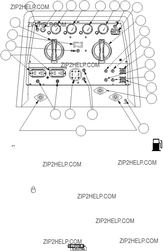
 RUN-
RUN-  STOP SWITCH
 , the engine runs at the high idle speed controlled by the governor.
 /
/  position, the idler oper- ates as follows:
 RANGE SWITCH & OUTPUT
 /REMOTE
  SWITCH


 CAUTION


 WARNING
 CAUTION
 WARNING
 WARNING

 WARNING
 CAUTION
 CAUTION
 CAUTION
 CAUTION


 TO
TO