CUSTOMER ASSISTANCE POLICY
The business of The Lincoln Electric Company is manufacturing and selling high quality welding equipment, consumables, and cutting equip- ment. Our challenge is to meet the needs of our customers and to exceed their expectations. On occasion, purchasers may ask Lincoln
Electric for advice or information about their use of our products. We respond to our customers based on the best information in our posses- sion at that time. Lincoln Electric is not in a position to warrant or guarantee such advice, and assumes no liability, with respect to such infor- mation or advice. We expressly disclaim any warranty of any kind, including any warranty of fitness for any customer??s particular purpose, with respect to such information or advice. As a matter of practical consideration, we also cannot assume any responsibility for updating or correcting any such information or advice once it has been given, nor does the provision of information or advice create, expand or alter any warranty with respect to the sale of our products.
Lincoln Electric is a responsive manufacturer, but the selection and use of specific products sold by Lincoln Electric is solely within the control of, and remains the sole responsibility of the customer. Many variables beyond the control of Lincoln Electric affect the results obtained in applying these types of fabrication methods and service requirements.
Subject to Change ??? This information is accurate to the best of our knowledge at the time of printing. Please refer to www.lincolnelectric.com for any updated information.
Please Examine Carton and Equipment For Damage Immediately
When this equipment is shipped, title passes to the purchaser upon receipt by the carrier. Consequently, Claims for material damaged in shipment must be made by the purchaser against the transportation company at the time the shipment is received.
Please record your equipment identification information below for future reference. This information can be found on your machine nameplate.
Product _________________________________________________________________________________
Model Number ___________________________________________________________________________
Code Number or Date Code_________________________________________________________________
Serial Number____________________________________________________________________________
Date Purchased___________________________________________________________________________
Where Purchased_________________________________________________________________________
Whenever you request replacement parts or information on this equipment, always supply the information you have recorded above. The code number is especially important when identifying the correct replacement parts.
On-Line Product Registration
-Register your machine with Lincoln Electric either via fax or over the Internet.
???For faxing: Complete the form on the back of the warranty statement included in the literature packet accompanying this machine and fax the form per the instructions printed on it.
???For On-Line Registration: Go to our WEB SITE at www.lincolnelectric.com. Choose ???Quick Links??? and then
???Product Registration???. Please complete the form and submit your registration.
Read this Operators Manual completely before attempting to use this equipment. Save this manual and keep it handy for quick reference. Pay particular attention to the safety instructions we have provided for your protection. The level of seriousness to be applied to each is explained below:
 WARNING
This statement appears where the information must be followed exactly to avoid serious personal injury or loss of life.
 CAUTION

 WARNING


 WELDING and CUTTING
 SPARKS can

 CYLINDER may explode


 if damaged.


 EN
EN 


 EN
EN 


 WARNING
 WARNING

 CAUTION
 WARNING
 WARNING
 WARNING
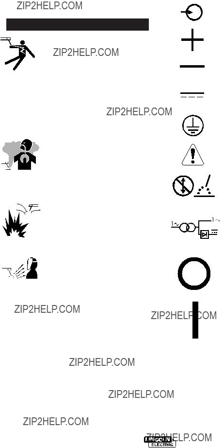
 WARNING
 ??? Keep flammable material away.

 CAUTION


 WARNING


 WARNING
 WARNING
 WARNING
 .020 Spark Gap


 WARNING
 CAUTION

 CAUTION
 CAUTION
 CAUTION
 CAUTION
 CAUTION