PR??CAUTIONS DE S??RET??
Pour votre propre protection lire et observer toutes les instructions et les pr??cautions de s??ret?? specifiques qui parraissent dans ce manuel aussi bien que les pr??cautions de s??ret?? g??n??rales suiv- antes:
S??ret?? Pour Soudage A L???Arc
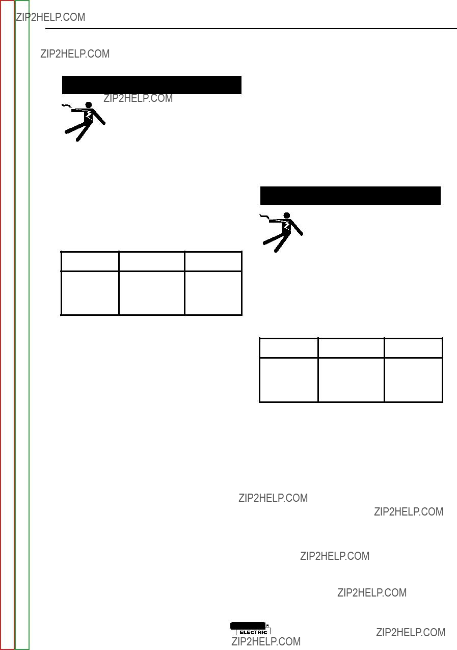
1.Protegez-vous contre la secousse ??lectrique:
a.Les circuits ?? l?????lectrode et ?? la pi??ce sont sous tension quand la machine ?? souder est en marche. Eviter toujours tout contact entre les parties sous tension et la peau nue ou les v??tements mouill??s. Porter des gants secs et sans trous pour isoler les mains.
b.Faire tr??s attention de bien s???isoler de la masse quand on soude dans des endroits humides, ou sur un plancher met- allique ou des grilles metalliques, principalement dans
les positions assis ou couch?? pour lesquelles une grande partie du corps peut ??tre en contact avec la masse.
c.Maintenir le porte-??lectrode, la pince de masse, le c??ble de soudage et la machine ?? souder en bon et s??r ??tat defonc- tionnement.
d.Ne jamais plonger le porte-??lectrode dans l???eau pour le refroidir.
e.Ne jamais toucher simultan??ment les parties sous tension des porte-??lectrodes connect??s ?? deux machines ?? souder parce que la tension entre les deux pinces peut ??tre le total de la tension ?? vide des deux machines.
f.Si on utilise la machine ?? souder comme une source de courant pour soudage semi-automatique, ces precautions pour le porte-??lectrode s???applicuent aussi au pistolet de soudage.
2.Dans le cas de travail au dessus du niveau du sol, se prot??ger contre les chutes dans le cas ou on recoit un choc. Ne jamais enrouler le c??ble-??lectrode autour de n???importe quelle partie du corps.
3.Un coup d???arc peut ??tre plus s??v??re qu???un coup de soliel, donc:
a.Utiliser un bon masque avec un verre filtrant appropri?? ainsi qu???un verre blanc afin de se prot??ger les yeux du rayon- nement de l???arc et des projections quand on soude ou quand on regarde l???arc.
b.Porter des v??tements convenables afin de prot??ger la peau de soudeur et des aides contre le rayonnement de l???arc.
c.Prot??ger l???autre personnel travaillant ?? proximit?? au soudage ?? l???aide d?????crans appropri??s et non-inflammables.
4.Des gouttes de laitier en fusion sont ??mises de l???arc de soudage. Se prot??ger avec des v??tements de protection libres de l???huile, tels que les gants en cuir, chemise ??paisse, pan- talons sans revers, et chaussures montantes.
5.Toujours porter des lunettes de s??curit?? dans la zone de soudage. Utiliser des lunettes avec ??crans lateraux dans les zones o?? l???on pique le laitier.
6.Eloigner les mat??riaux inflammables ou les recouvrir afin de pr??venir tout risque d???incendie d?? aux ??tincelles.
7.Quand on ne soude pas, poser la pince ?? une endroit isol?? de la masse. Un court-circuit accidental peut provoquer un ??chauffement et un risque d???incendie.
8.S???assurer que la masse est connect??e le plus pr??s possible de la zone de travail qu???il est pratique de le faire. Si on place la masse sur la charpente de la construction ou d???autres endroits ??loign??s de la zone de travail, on augmente le risque de voir passer le courant de soudage par les chaines de levage, c??bles de grue, ou autres circuits. Cela peut provoquer des risques d???incendie ou d???echauffement des chaines et des c??bles jusqu????? ce qu???ils se rompent.
9.Assurer une ventilation suffisante dans la zone de soudage. Ceci est particuli??rement important pour le soudage de t??les galvanis??es plomb??es, ou cadmi??es ou tout autre m??tal qui produit des fume??s toxiques.
10.Ne pas souder en pr??sence de vapeurs de chlore provenant d???op??rations de d??graissage, nettoyage ou pistolage. La chaleur ou les rayons de l???arc peuvent r??agir avec les vapeurs du solvant pour produire du phosg??ne (gas fortement toxique) ou autres produits irritants.
11.Pour obtenir de plus amples renseignements sur la s??ret??, voir le code ???Code for safety in welding and cutting??? CSA Standard W 117.2-1974.
PR??CAUTIONS DE S??RET?? POUR
LES MACHINES ?? SOUDER ??
TRANSFORMATEUR ET ??
REDRESSEUR
1.Relier ?? la terre le chassis du poste conformement au code de l?????lectricit?? et aux recommendations du fabricant. Le dispositif de montage ou la piece ?? souder doit ??tre branch?? ?? une bonne mise ?? la terre.
2.Autant que possible, I???installation et l???entretien du poste seront effectu??s par un ??lectricien qualifi??.
3.Avant de faires des travaux ?? l???interieur de poste, la debranch- er ?? l???interrupteur ?? la boite de fusibles.
4.Garder tous les couvercles et dispositifs de s??ret?? ?? leur place.

 WARNING


 WARNING
 WARNING
 WARNING

 WARNING
 WARNING
 WARNING
 WARNING


 WARNING


 WARNING
 WARNING
 WARNING
 WARNING


 WARNING


 WARNING
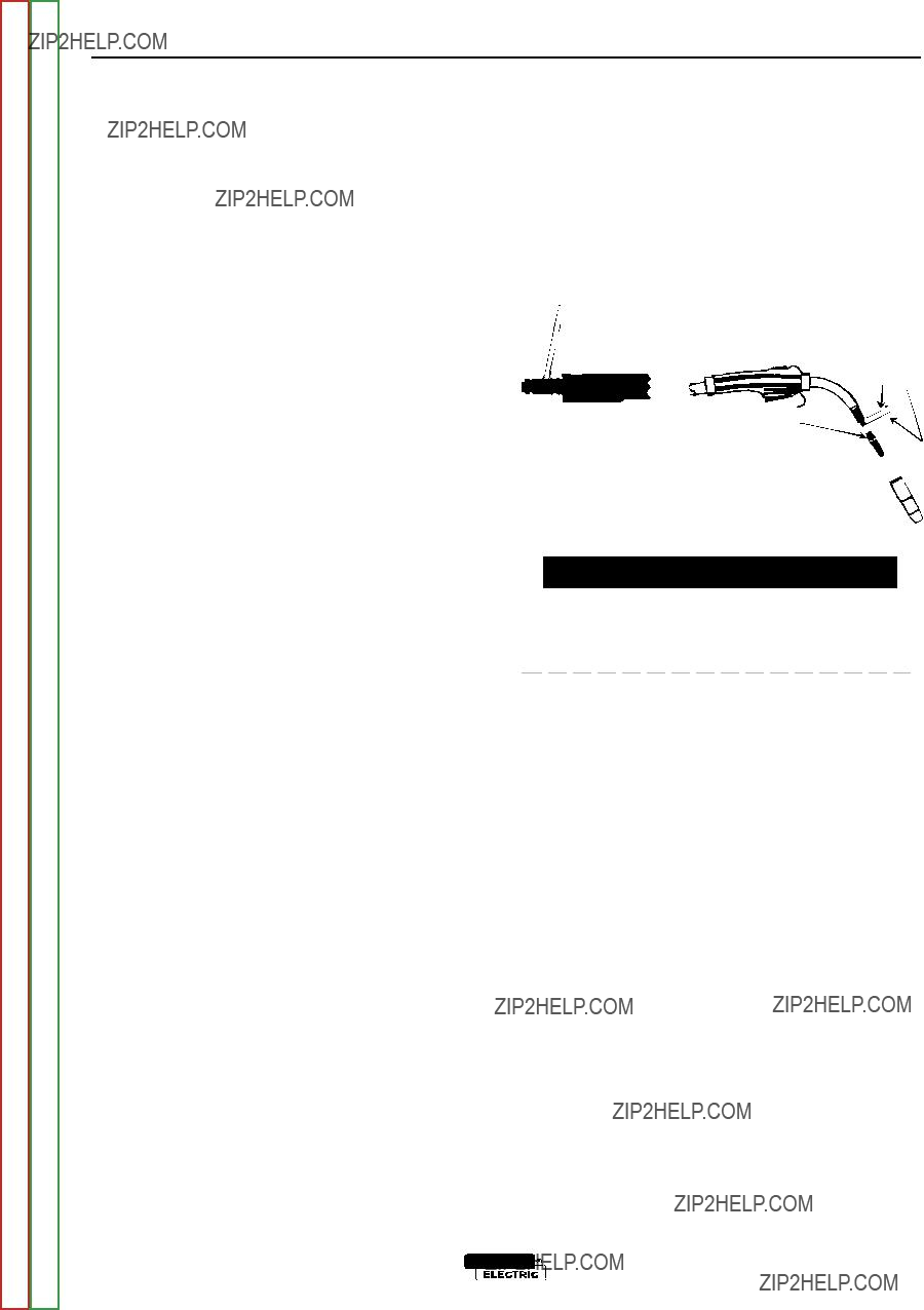


 WARNING
 WARNING
 CAUTION
 CAUTION
 CAUTION
 CAUTION
 CAUTION
 CAUTION
 CAUTION
 CAUTION
 CAUTION
 WARNING
 WARNING
 WARNING

 WARNING
 WARNING
 WARNING
 WARNING
 WARNING


 WARNING
 Contactor
 CAUTION


 WARNING

 WARNING


 5/16" Sheet


 9/16" Bolt
 Monuting

 Screws


 WARNING


 WARNING
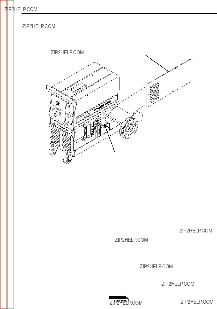


 }
} 3/8" Nuts & Lock washers


 WARNING


 -
- 


 WARNING

 WARNING
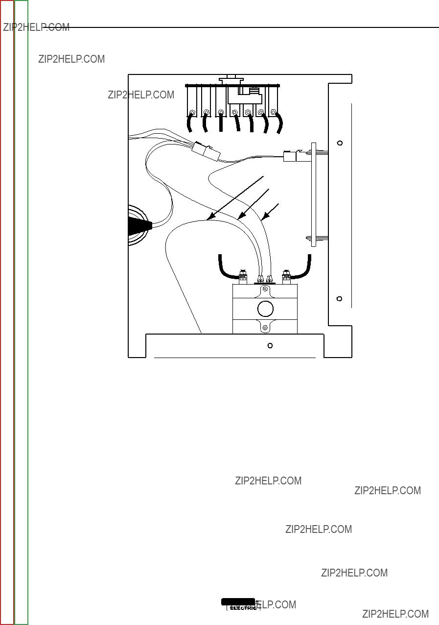
 Contactor


 1104B
1104B

 1104A
1104A 1
1 
 2
2 
 3
3 
 4
4 
 5
5 
 6
6 


 8
8 
 9
9 
 10
10 
 11
11 
 12
12 
 13
13 
 14
14 
 15
15 
 16
16 


 COM
COM COM
COM