RETURN TO MAIN MENU

K520 UTILITY CART

IM468-A

August, 2005

Safety Depends on You

Lincoln arc welding and cutting equipment is designed and built with safety in mind. However, your overall safety can be increased by proper installation ... and thought- ful operation on your part. DO

NOT INSTALL, OPERATE OR

REPAIR THIS EQUIPMENT

WITHOUT READING THIS

MANUAL AND THE SAFETY

PRECAUTIONS CONTAINED THROUGHOUT . And, most importantly, think before you act and be careful.

OPERATOR???S MANUAL

Copyright ?? 2005 Lincoln Global Inc.

??? World's Leader in Welding and Cutting Products ???

??? Sales and Service through Subsidiaries and Distributors Worldwide ???

Cleveland, Ohio 44117-1199 U.S.A. TEL: 216.481.8100 FAX: 216.486.1751 WEB SITE: www.lincolnelectric.com

i

SAFETY

i

WARNING

CALIFORNIA PROPOSITION 65 WARNINGS

Diesel engine exhaust and some of its constituents are known to the State of California to cause can- cer, birth defects, and other reproductive harm.

The Above For Diesel Engines

The engine exhaust from this product contains chemicals known to the State of California to cause cancer, birth defects, or other reproductive harm.

The Above For Gasoline Engines

ARC WELDING CAN BE HAZARDOUS. PROTECT YOURSELF AND OTHERS FROM POSSIBLE SERIOUS INJURY OR DEATH.

KEEP CHILDREN AWAY. PACEMAKER WEARERS SHOULD CONSULT WITH THEIR DOCTOR BEFORE OPERATING.

Read and understand the following safety highlights. For additional safety information, it is strongly recommended that you purchase a copy of ???Safety in Welding & Cutting - ANSI Standard Z49.1??? from the American Welding Society, P.O. Box 351040, Miami, Florida 33135 or CSA Standard W117.2-1974. A Free copy of ???Arc Welding Safety??? booklet E205 is available from the Lincoln Electric Company, 22801 St. Clair Avenue, Cleveland, Ohio 44117-1199.

BE SURE THAT ALL INSTALLATION, OPERATION, MAINTENANCE AND REPAIR PROCEDURES ARE

PERFORMED ONLY BY QUALIFIED INDIVIDUALS.

FOR ENGINE powered equipment.

1.a. Turn the engine off before troubleshooting and maintenance work unless the maintenance work requires it to be running.

____________________________________________________

1.b. Operate engines in open, well-ventilated areas or vent the engine exhaust fumes

outdoors.

____________________________________________________

1.c. Do not add the fuel near an open flame welding arc or when the engine is running.

Stop the engine and allow it to cool before refueling to prevent spilled fuel from vaporiz- ing on contact with hot engine parts and igniting. Do not spill fuel when filling tank. If fuel is spilled, wipe it up and do not start engine until fumes have been eliminated.

____________________________________________________

1.d. Keep all equipment safety guards, covers and devices in position and in good repair.Keep hands, hair, clothing and tools away from V-belts, gears, fans and all other moving parts when starting, operating or repairing equipment.

____________________________________________________

1.e. In some cases it may be necessary to remove safety guards to perform required maintenance. Remove guards only when necessary and replace them when the maintenance requiring their removal is complete. Always use the greatest care when working near moving parts.

___________________________________________________

1.f. Do not put your hands near the engine fan.

Do not attempt to override the governor or idler by pushing on the throttle control rods while the engine is running.

___________________________________________________

1.g. To prevent accidentally starting gasoline engines while turning the engine or welding generator during maintenance work, disconnect the spark plug wires, distributor cap or magneto wire as appropriate.

1.h. To avoid scalding, do not remove the radiator pressure cap when the engine is hot.

ELECTRIC AND

MAGNETIC FIELDS may be dangerous

2.a. Electric current flowing through any conductor causes localized Electric and Magnetic Fields (EMF). Welding current creates EMF fields around welding cables and welding machines

2.b. EMF fields may interfere with some pacemakers, and welders having a pacemaker should consult their physician before welding.

2.c. Exposure to EMF fields in welding may have other health effects which are now not known.

2.d. All welders should use the following procedures in order to minimize exposure to EMF fields from the welding circuit:

2.d.1. Route the electrode and work cables together - Secure them with tape when possible.

2.d.2. Never coil the electrode lead around your body.

2.d.3. Do not place your body between the electrode and work cables. If the electrode cable is on your right side, the work cable should also be on your right side.

2.d.4. Connect the work cable to the workpiece as close as possible to the area being welded.

2.d.5. Do not work next to welding power source.

Mar ???95

ELECTRIC SHOCK can kill.

3.a. The electrode and work (or ground) circuits are electrically ???hot??? when the welder is on. Do not touch these ???hot??? parts with your bare skin or wet clothing. Wear dry, hole-free

gloves to insulate hands.

3.b. Insulate yourself from work and ground using dry insulation. Make certain the insulation is large enough to cover your full area of physical contact with work and ground.

In addition to the normal safety precautions, if welding must be performed under electrically hazardous conditions (in damp locations or while wearing wet clothing; on metal structures such as floors, gratings or scaffolds; when in cramped positions such as sitting, kneeling or lying, if there is a high risk of unavoidable or accidental contact with the workpiece or ground) use the following equipment:

???Semiautomatic DC Constant Voltage (Wire) Welder.

???DC Manual (Stick) Welder.

???AC Welder with Reduced Voltage Control.

3.c. In semiautomatic or automatic wire welding, the electrode, electrode reel, welding head, nozzle or semiautomatic welding gun are also electrically ???hot???.

3.d. Always be sure the work cable makes a good electrical connection with the metal being welded. The connection should be as close as possible to the area being welded.

3.e. Ground the work or metal to be welded to a good electrical (earth) ground.

3.f. Maintain the electrode holder, work clamp, welding cable and welding machine in good, safe operating condition. Replace damaged insulation.

3.g. Never dip the electrode in water for cooling.

3.h. Never simultaneously touch electrically ???hot??? parts of electrode holders connected to two welders because voltage between the two can be the total of the open circuit voltage of both welders.

3.i. When working above floor level, use a safety belt to protect yourself from a fall should you get a shock.

3.j. Also see Items 6.c. and 8.

ARC RAYS can burn.

4.a. Use a shield with the proper filter and cover plates to protect your eyes from sparks and the rays of the arc when welding or observing open arc welding. Headshield and filter lens should conform to ANSI Z87. I standards.

4.b. Use suitable clothing made from durable flame-resistant material to protect your skin and that of your helpers from the arc rays.

4.c. Protect other nearby personnel with suitable, non-flammable screening and/or warn them not to watch the arc nor expose themselves to the arc rays or to hot spatter or metal.

FUMES AND GASES can be dangerous.

5.a. Welding may produce fumes and gases hazardous to health. Avoid breathing these fumes and gases.When welding, keep your head out of the fume. Use enough ventilation and/or exhaust at the arc to keep

fumes and gases away from the breathing zone. When

welding with electrodes which require special ventilation such as stainless or hard facing (see instructions on container or MSDS) or on lead or cadmium plated steel and other metals or coatings which produce highly toxic fumes, keep exposure as low as possible and below Threshold Limit Values (TLV) using local exhaust or mechanical ventilation. In confined spaces or in some circumstances, outdoors, a respirator may be required. Additional precautions are also required when welding on galvanized steel.

5.b. Do not weld in locations near chlorinated hydrocarbon vapors coming from degreasing, cleaning or spraying operations. The heat and rays of the arc can react with solvent vapors to form phosgene, a highly toxic gas, and other irritating prod- ucts.

5.c. Shielding gases used for arc welding can displace air and cause injury or death. Always use enough ventilation, especially in confined areas, to insure breathing air is safe.

5.d. Read and understand the manufacturer???s instructions for this equipment and the consumables to be used, including the material safety data sheet (MSDS) and follow your employer???s safety practices. MSDS forms are available from your welding distributor or from the manufacturer.

5.e. Also see item 1.b.

Mar ???95

iii

SAFETY

iii

WELDING SPARKS can cause fire or explosion.

6.a. Remove fire hazards from the welding area.

If this is not possible, cover them to prevent the welding sparks from starting a fire. Remember that welding sparks and hot

materials from welding can easily go through small cracks and openings to adjacent areas. Avoid welding near hydraulic lines. Have a fire extinguisher readily available.

6.b. Where compressed gases are to be used at the job site, special precautions should be used to prevent hazardous situations. Refer to ???Safety in Welding and Cutting??? (ANSI

Standard Z49.1) and the operating information for the equipment being used.

6.c. When not welding, make certain no part of the electrode circuit is touching the work or ground. Accidental contact can cause overheating and create a fire hazard.

6.d. Do not heat, cut or weld tanks, drums or containers until the proper steps have been taken to insure that such procedures will not cause flammable or toxic vapors from substances inside. They can cause an explosion even though they have been ???cleaned???. For information, purchase ???Recommended Safe Practices for the Preparation for Welding and Cutting of Containers and Piping That Have Held Hazardous

Substances???, AWS F4.1 from the American Welding Society

(see address above).

6.e. Vent hollow castings or containers before heating, cutting or welding. They may explode.

6.f. Sparks and spatter are thrown from the welding arc. Wear oil free protective garments such as leather gloves, heavy shirt, cuffless trousers, high shoes and a cap over your hair. Wear ear plugs when welding out of position or in confined places.

Always wear safety glasses with side shields when in a welding area.

6.g. Connect the work cable to the work as close to the welding area as practical. Work cables connected to the building framework or other locations away from the welding area increase the possibility of the welding current passing through lifting chains, crane cables or other alternate cir- cuits. This can create fire hazards or overheat lifting chains or cables until they fail.

6.h. Also see item 1.c.

CYLINDER may explode if damaged.

7.a. Use only compressed gas cylinders

containing the correct shielding gas for the process used and properly operating regulators designed for the gas and

pressure used. All hoses, fittings, etc. should be suitable for the application and maintained in good condition.

7.b. Always keep cylinders in an upright position securely chained to an undercarriage or fixed support.

7.c. Cylinders should be located:

???Away from areas where they may be struck or subjected to physical damage.

???A safe distance from arc welding or cutting operations and any other source of heat, sparks, or flame.

7.d. Never allow the electrode, electrode holder or any other electrically ???hot??? parts to touch a cylinder.

7.e. Keep your head and face away from the cylinder valve outlet when opening the cylinder valve.

7.f. Valve protection caps should always be in place and hand tight except when the cylinder is in use or connected for use.

7.g. Read and follow the instructions on compressed gas cylinders, associated equipment, and CGA publication P-l, ???Precautions for Safe Handling of Compressed Gases in

Cylinders,??? available from the Compressed Gas Association 1235 Jefferson Davis Highway, Arlington, VA 22202.

FOR ELECTRICALLY powered equipment.

8.a. Turn off input power using the disconnect switch at the fuse box before working on the equipment.

8.b. Install equipment in accordance with the U.S. National Electrical Code, all local codes and the manufacturer???s recommendations.

8.c. Ground the equipment in accordance with the U.S. National Electrical Code and the manufacturer???s recommendations.

Mar ???95

iv

SAFETY

iv

PR??CAUTIONS DE S??RET??

Pour votre propre protection lire et observer toutes les instructions et les pr??cautions de s??ret?? specifiques qui parraissent dans ce manuel aussi bien que les pr??cautions de s??ret?? g??n??rales suiv- antes:

S??ret?? Pour Soudage A L???Arc

1.Protegez-vous contre la secousse ??lectrique:

a.Les circuits ?? l?????lectrode et ?? la pi??ce sont sous tension quand la machine ?? souder est en marche. Eviter toujours tout contact entre les parties sous tension et la peau nue ou les v??tements mouill??s. Porter des gants secs et sans trous pour isoler les mains.

b.Faire tr??s attention de bien s???isoler de la masse quand on soude dans des endroits humides, ou sur un plancher metallique ou des grilles metalliques, principalement dans les positions assis ou couch?? pour lesquelles une grande partie du corps peut ??tre en contact avec la masse.

c.Maintenir le porte-??lectrode, la pince de masse, le c??ble de soudage et la machine ?? souder en bon et s??r ??tat defonctionnement.

d.Ne jamais plonger le porte-??lectrode dans l???eau pour le refroidir.

e.Ne jamais toucher simultan??ment les parties sous tension des porte-??lectrodes connect??s ?? deux machines ?? souder parce que la tension entre les deux pinces peut ??tre le total de la tension ?? vide des deux machines.

f.Si on utilise la machine ?? souder comme une source de courant pour soudage semi-automatique, ces precautions pour le porte-??lectrode s???applicuent aussi au pistolet de soudage.

2.Dans le cas de travail au dessus du niveau du sol, se prot??ger contre les chutes dans le cas ou on recoit un choc. Ne jamais enrouler le c??ble-??lectrode autour de n???importe quelle partie du corps.

3.Un coup d???arc peut ??tre plus s??v??re qu???un coup de soliel, donc:

a.Utiliser un bon masque avec un verre filtrant appropri?? ainsi qu???un verre blanc afin de se prot??ger les yeux du ray-

onnement de l???arc et des projections quand on soude ou quand on regarde l???arc.

b.Porter des v??tements convenables afin de prot??ger la peau de soudeur et des aides contre le rayonnement de l???arc.

c.Prot??ger l???autre personnel travaillant ?? proximit?? au soudage ?? l???aide d?????crans appropri??s et non-inflammables.

4.Des gouttes de laitier en fusion sont ??mises de l???arc de soudage. Se prot??ger avec des v??tements de protection libres de l???huile, tels que les gants en cuir, chemise ??paisse, pan- talons sans revers, et chaussures montantes.

5.Toujours porter des lunettes de s??curit?? dans la zone de soudage. Utiliser des lunettes avec ??crans lateraux dans les zones o?? l???on pique le laitier.

6.Eloigner les mat??riaux inflammables ou les recouvrir afin de pr??venir tout risque d???incendie d?? aux ??tincelles.

7.Quand on ne soude pas, poser la pince ?? une endroit isol?? de la masse. Un court-circuit accidental peut provoquer un ??chauffement et un risque d???incendie.

8.S???assurer que la masse est connect??e le plus pr??s possible de la zone de travail qu???il est pratique de le faire. Si on place la masse sur la charpente de la construction ou d???autres endroits ??loign??s de la zone de travail, on augmente le risque de voir passer le courant de soudage par les chaines de lev- age, c??bles de grue, ou autres circuits. Cela peut provoquer des risques d???incendie ou d???echauffement des chaines et des c??bles jusqu????? ce qu???ils se rompent.

9.Assurer une ventilation suffisante dans la zone de soudage.

Ceci est particuli??rement important pour le soudage de t??les galvanis??es plomb??es, ou cadmi??es ou tout autre m??tal qui produit des fume??s toxiques.

10.Ne pas souder en pr??sence de vapeurs de chlore provenant d???op??rations de d??graissage, nettoyage ou pistolage. La chaleur ou les rayons de l???arc peuvent r??agir avec les vapeurs du solvant pour produire du phosg??ne (gas fortement toxique) ou autres produits irritants.

11.Pour obtenir de plus amples renseignements sur la s??ret??, voir le code ???Code for safety in welding and cutting??? CSA Standard W 117.2-1974.

PR??CAUTIONS DE S??RET?? POUR

LES MACHINES ?? SOUDER ??

TRANSFORMATEUR ET ??

REDRESSEUR

1.Relier ?? la terre le chassis du poste conformement au code de l?????lectricit?? et aux recommendations du fabricant. Le dispositif de montage ou la piece ?? souder doit ??tre branch?? ?? une bonne mise ?? la terre.

2.Autant que possible, I???installation et l???entretien du poste seront effectu??s par un ??lectricien qualifi??.

3.Avant de faires des travaux ?? l???interieur de poste, la debranch- er ?? l???interrupteur ?? la boite de fusibles.

4.Garder tous les couvercles et dispositifs de s??ret?? ?? leur place.

Mar. ???93

to take pride in using this Lincoln Electric Company product ????????? as

Please Examine Carton and Equipment For Damage Immediately

When this equipment is shipped, title passes to the purchaser upon receipt by the carrier. Consequently, Claims for material damaged in shipment must be made by the purchaser against the transportation company at the time the shipment is received.

Please record your equipment identification information below for future reference. This information can be found on your machine nameplate.

Product _________________________________________________________________________________

K520 Utility Cart

Model Number ___________________________________________________________________________

Code Number or Date Code_________________________________________________________________

Serial Number____________________________________________________________________________

Date Purchased___________________________________________________________________________

Where Purchased_________________________________________________________________________

Whenever you request replacement parts or information on this equipment, always supply the information you have recorded above. The code number is especially important when identifying the correct replacement parts.

On-Line Product Registration

- Register your machine with Lincoln Electric either via fax or over the Internet.

??? For faxing: Complete the form on the back of the warranty statement included in the literature packet accompanying this machine and fax the form per the instructions printed on it.

??? For On-Line Registration: Go to our WEB SITE at www.lincolnelectric.com. Choose ???Quick Links??? and then ???Product Registration???. Please complete the form and submit your registration.

Read this Operators Manual completely before attempting to use this equipment. Save this manual and keep it handy for quick reference. Pay particular attention to the safety instructions we have provided for your protection. The level of seriousness to be applied to each is explained below:

WARNING

This statement appears where the information must be followed exactly to avoid serious personal injury or loss of life.

CAUTION

This statement appears where the information must be followed to avoid minor personal injury or damage to this equipment.

PRODUCT DESCRIPTION

The K520 Utility Cart is designed for mounting and transporting the Lincoln family of small SP and Weld- Pak type welders and the small AC types. It has provi- sions for mounting a single gas cylinder when used with a SP type welder or Weld-Pak type.

This unit is compact enough for home use, yet rugged enough for commercial use. It is easily moved on front swivel casters, and large, easy rolling rear wheels. A unique feature is the adjustable height handle, which allows comfortable and convenient operation by any operator. In addition to space for a welder and gas bottle, space has been provided for carrying the oper- ator???s tools and welding accessories.

SPECIFICATIONS

CYLINDER CAPACITY:

Maximum Outside Diameter 8.1" (20.6cm) Maximum Height 46" (117cm)

Maximum Weight 100 lbs (45kg)

MAXIMUM CAPACITY:

Welder alone 100 lbs (45kg)

Welder with Gas Cylinder 200 lbs (90kg)

TOOLS REQUIRED FOR UTILITY CART

ASSEMBLY:

Phillips Screwdriver (#I) 7/16 inch wrench Pliers

STEP 1

Carefully remove the cart, wheels, axle, handle, and the loose parts bag from the carton. Check the parts in the loose parts bag against the list provided. Note that some parts are used for assembling the cart, while those in the separate bag are for attaching your welder to the cart.

Leave all screws slightly loose until STEP 8.

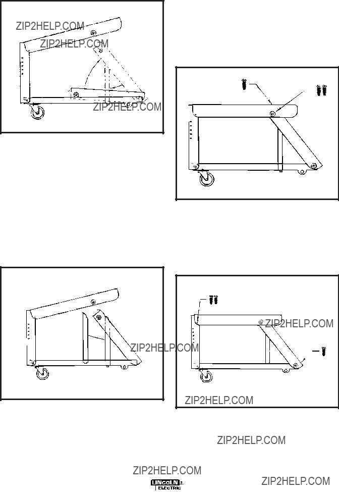
STEP 2 (SEE FIGURE 1)

Carefully unfold the cart by raining the Front Upright to the vertical position. Insert one 10-24 x .375 screw through the lower front. The Front Upright will now stay in the vertical position.

CART ASSEMBLY INSTRUCTIONS

PARTS REQUIRED:

FIGURE 1

STEP 3 (SEE FIGURE 2)

Raise up the rear portion of the Top Shelf, and lift the Rear Upright. As the Rear Upright is raised, the Tank Support will become vertical. Insert the tabs in the bot- tom of the Tank Support into the corresponding slots in the Bottom Shelf. Lower the Top Shelf until it is sup- ported by the rear upright.

FIGURE 2

STEP 4 (SEE FIGURE 3)

With the Rear Shelf still raised, install the right hand Vertical Gusset alongside the Tank Support. Begin by placing the tab in the bottom of the Vertical Gusset into the slot in the Bottom Shelf, just to the right of the Rear Upright. Insert the Vertical Gusset???s upper tab into the Rear Upright. Repeat this with the left hand Vertical Gusset. Lower the Top Shelf until it is sup- ported by the Rear Upright.

FIGURE 3

STEP 5 (SEE FIGURE 4)

Screw the Top Shelf and the Rear Support together using 10-24 x .375 screws. For easiest assembly, use two screws to first secure the sides of the Top Shelf to the Rear Upright. Next, put one more screw through the top of the Top Shelf, into the Rear Support.

FIGURE 4

STEP 6 (SEE FIGURE 5)

Secure the Rear Upright to the Bottom Shelf using one 10-24 x .375 screw.

FIGURE 5

STEP 7 (SEE FIGURE 5)

Place the remaining two screws through the sides of the Top Shelf into the Front Upright.

STEP 8

Tighten all eleven screws (7 inserted by the customer, 4 inserted at the factory) used to hold the Utility Cart together.

STEP 9 (SEE FIGURE 6)

Stand the Utility Cart on its front. Slide the Rear Axle through the mounting holes provided. Place the inside washers, then the Wheels, then the outside washers. Secure the wheels in place with cotter keys in the holes provided and bend the ends to secure them in place. Place the Utility Cart in the upright position.

FIGURE 6

STEP 10

The front casters are installed at the factory.

STEP 11 (SEE FIGURE 7)

Insert the Handle as shown. Slide it into the Front Upright, adjusting it to a comfortable position. Secure the handle using the two 1/4-20 x 1.50 screws by aligning the hole in the end of the handle with one set of holes in the Front Upright, and sliding the screws through the holes. Secure the screws with one lock- washer and one nut on each screw.

FIGURE 7

The Utility Cart is now fully assembled. Refer to the following instructions for mounting your specific welder to the Utility Cart.

WELDER MOUNTING INSTRUCTIONS

Small SP welder and Weldpak to the Utility Cart

Parts Required:

Refer to FIGURE 8 while mounting your welder.

STEP 1

Secure one Welder Clip in position with a bolt, lock-

washer, and nut Note that the overhanging edge ofFIGURE 8 the Welder Clip must face toward the door of the

welder, so that the welder covers the bolt head when installed.

STEP 2

Position your welder as shown. Open the welder door, and slide the welder over the bolt head, engag- ing the lower lip of the welder with the overhanging edge of the Welder Clip.

STEP 3

On the opposite side of the welder, remove the front and rear self-tapping screws which secure the case side. Attach two Welder Clips to the case side, using the same holes and screws. The overhanging edge of the Welder Clip must face away from the welder.

STEP 4

Adjust the welder position so that the holes in the Welder Clips line up with holes in the Utility Cart as shown. Secure the clips to the Cart with two bolts, two lockwashers, and two nuts.

CAUTION

THE HANDLE ON YOUR WELDER IS NOT TO BE

USED FOR LIFTING WHEN THE WELDER IS

ATTACHED TO THE UTILITY CART. THE HANDLE

IS FOR LIFTING THE WELDER ONLY! DO NOT LIFT

BY THE HANDLE WHEN THE CART IS ATTACHED!

------------------------------------------------------------------------

See GAS CYLINDER MOUNTING INSTRUCTIONS if a cylinder is to be used.

AC-225-C WELDER TO THE UTILITY

CART

Refer to FIGURE 9 while mounting your AC-225-C welder.

Position the AC-225-C as shown. Attach the AC-225- C with four 1/4 x 1 1/4 in. Self-tapping screws from underneath using the holes provided in the base of the AC-225-C and the Utility Cart.

If desired, the chain and buckle/strap assemblies may be removed, since a gas bottle is not required when

CAUTION

welding with an AC-225-C.

THE HANDLE ON YOUR AC-225-C IS NOT TO BE

USED FOR LIFTING WHEN THE AC-225C IS

ATTACHED TO THE UTILITY CART. THE HANDLE

IS FOR LIFTING THE AC-225-C ONLY! DO NOT

LIFT BY THE HANDLE WHEN THE CART IS

ATTACHED.

------------------------------------------------------------------------

GAS CYLINDER MOUNTING

INSTRUCTIONS

WARNING

CYLINDER could explode if damaged.

??? Keep cylinder upright and chained to a support.

???Keep cylinder away from areas where it could be damaged.

???Never lift welder with cylinder attached.

???Never allow the welding electrode to touch the cylinder.

???Keep cylinder away from welding and other live

electrical circuits.

___________________________________________

GAS CYLINDERS LESS THAN 15 INCHES (40CM) TALL

Set the cylinder upright on the rear of the Bottom Shelf. Secure in place with the Strap and Buckle Assembly. The cylinder must be held tightly against theTank Support. The chain is not used.

GAS CYLINDERS GREATER THAN 15 INCHES (40CM) TALL

Set the cylinder upright on the rear of the Bottom Shelf. Secure in place by looping the Chain around the bottle, and passing the end of the chain through the keyhole slot in the Top Shelf. Lock the link that gives the tightest fit around the bottle in the narrow slot. Secure the lower portion of the bottle with the strap and Buckel Assembly. Both the Chain and the Strap Assembly must be used.

FIGURE 9

OPERATING INSTRUCTIONS

The Utility Cart is designed for hand moving only. Do not attempt to pull the cart with any mechanized vehi- cle.

Use the cart on a level surface only. Moving the cart over steep inclines could cause the cart to roll out of control, or tip over. Either situation could result in damage to the cart, welder, or injury to the operator.

The K520 Utility Cart is designed to work only with the Lincoln products listed below. Use with other welders or equipment could cause overloading, or result in unstable operations.

PRODUCTS SUPPORTED:

AC225-C

INVERTEC V160-S, INVERTEC V160-T

INVERTEC V205T AC/DC

PRO-CUT 25

Pro-MIG 175, Pro-Core 100

MIG PAK 10, MIG PAK 15, PRO 100, PRO 155,

PRO MIG 135

SP-75, SP-85, SP-100, SP-100-I, SP-100 T,

SP-125 PLUS, SP-130 T, SP-135T, SP135PLUS,

SP-140-I, SP170-I, SP-170 T, SP-175T, SP175 PLUS

Weld-Pak 100, Weld-Pak 100 HD, Weld-Pak 100

PLUS, Weld-Pak 125, Weld-Pak 155, UWW 170

Weld-Pak 175HD, Weld-Pak 3200HD,

Weld-Pak 5000HD

Weldmark 135 Plus

N.A. TAP HOLE TO #10-24 UNC-2B THREAD (3 PLACES).

15

A

A

6

5

9

A.01

G2300

7-A

PRINT DIMENSION

7-A

Chinese

Korean

Arabic

READ AND UNDERSTAND THE MANUFACTURER???S INSTRUCTION FOR THIS EQUIPMENT AND THE CONSUMABLES TO BE

USED AND FOLLOW YOUR EMPLOYER???S SAFETY PRACTICES.

SE RECOMIENDA LEER Y ENTENDER LAS INSTRUCCIONES DEL FABRICANTE PARA EL USO DE ESTE EQUIPO Y LOS

CONSUMIBLES QUE VA A UTILIZAR, SIGA LAS MEDIDAS DE SEGURIDAD DE SU SUPERVISOR.

LISEZ ET COMPRENEZ LES INSTRUCTIONS DU FABRICANT EN CE QUI REGARDE CET EQUIPMENT ET LES PRODUITS A

ETRE EMPLOYES ET SUIVEZ LES PROCEDURES DE SECURITE DE VOTRE EMPLOYEUR.

LESEN SIE UND BEFOLGEN SIE DIE BETRIEBSANLEITUNG DER ANLAGE UND DEN ELEKTRODENEINSATZ DES HER-

STELLERS. DIE UNFALLVERH??TUNGSVORSCHRIFTEN DES ARBEITGEBERS SIND EBENFALLS ZU BEACHTEN.

Chinese

Korean

Arabic

LEIA E COMPREENDA AS INSTRU????ES DO FABRICANTE PARA ESTE EQUIPAMENTO E AS PARTES DE USO, E SIGA AS

PR??TICAS DE SEGURAN??A DO EMPREGADOR.

??? World's Leader in Welding and Cutting Products ???

??? Sales and Service through Subsidiaries and Distributors Worldwide ???

Cleveland, Ohio 44117-1199 U.S.A. TEL: 216.481.8100 FAX: 216.486.1751 WEB SITE: www.lincolnelectric.com