95Li Summit Trainer
Assembly Instructions
95Li Summit Trainer
Assembly Instructions

Congratulations...
and welcome to the world of
The following Parts List and the
Please take special note of the following important points prior to choosing a location and beginning assembly of the Summit Trainer.

IMPORTANT SAFETY INSTRUCTIONS!
DO NOT LOCATE THE SUMMIT TRAINER OUTDOORS, NEAR SWIMMING POOLS, OR IN AREAS OF HIGH
HUMIDITY.
DO NOT OPERATE YOUR SUMMIT TRAINER IF IT HAS BEEN DROPPED, DAMAGED, OR EVEN PARTIALLY
IMMERSED IN WATER. IF THIS OCCURS, CONTACT LIFE FITNESS CUSTOMER SUPPORT SERVICES AT
THE NUMBER IN THE OPERATION MANUAL.
DO NOT LOCATE THE SUMMIT TRAINER ANY CLOSER THAN 30 INCHES (76 CM ) TO A TELEVISION SET.
DO NOT LOCATE ADDITIONAL SUMMIT TRAINERS ANY CLOSER THAN 42 INCHES (107 CM) FROM
CENTER TO CENTER TO AVOID INTERFERENCE (CROSS TALK) BETWEEN HEART RATE MONITORS.
DO KEEP THE AREA AROUND YOUR SUMMIT TRAINER CLEAR OF ANY OBSTRUCTIONS, INCLUDING
WALLS AND FURNITURE. ENSURE THAT THERE IS AT LEAST A 12 INCH (30CM) CLEARANCE IN FRONT
OF THE SUMMIT TRAINER.
DO VERIFY THE CONTENTS OF THE DELIVERY CARTON AGAINST THE ACCOMPANYING PARTS LIST
PRIOR TO SETTING THE CARTONS AND SHIPPING MATERIAL ASIDE. IF ANY PARTS ARE MISSING,
CONTACT LIFE FITNESS CUSTOMER SUPPORT SERVICES AT THE NUMBER LISTED IN THE OPERATION
MANUAL. SAVE THE SHIPPING CARTONS IN CASE OF RETURN.
DO READ THE ENTIRE OPERATION MANUAL PRIOR TO ATTEMPTING TO OPERATE THIS MACHINE AS
THIS IS ESSENTIAL FOR PROPER USE.
CONSIGNES DE SECURITE IMPORTANTES!
NE PLACEZ PAS L'APPAREIL ?? L'EXT??RIEUR, PR??S D'UNE PISCINE OU DANS UN ENDROIT TR??S
HUMIDE
NE FAITES PAS FONCTIONNER L'APPAREIL S'IL EST TOMB??, S'IL A ??T?? ENDOMMAG?? OU S'IL A ??T??
PARTIELLEMENT PLONG?? DANS L'EAU. SI CELA S'EST PRODUIT, CONTACTEZ LE SERVICE
DE LIFE FITNESS AU NUM??RO FOURNI DANS LE MANUEL D'UTILISATION
NE PLACEZ PAS L'APPAREIL ?? MOINS DE 76 CM D'UN POSTE DE T??L??VISION
NE PLACEZ PAS D'AUTRES APPAREILS DU M??ME TYPE ?? PROXIMIT??. UN ESPACE D'AU MOINS 107 CM
DOIT ??TRE OBSERV?? ENTRE LES PARTIES CENTRALES DE DEUX APPAREILS AFIN D'??VITER LES
INTERF??RENCES ENTRE LES CONTR??LEURS DE RYTHME CARDIAQUE.
MAINTENEZ LA ZONE AUTOUR DE L'APPAREIL LIBRE DE TOUTE OBSTRUCTION, Y COMPRIS MURS ET
MEUBLES. VEILLEZ ?? LAISSER UN D??GAGEMENT D'AU MOINS 30 CM DEVANT L'APPAREIL
V??RIFIEZ SI L'EMBALLAGE CONTIENT TOUTES LES PI??CES DE LA LISTE JOINTE AVANT DE LE METTRE
DE C??T??. SI DES PI??CES SONT ABSENTES, CONTACTEZ LE SERVICE
AU NUM??RO INDIQU?? DANS LE MANUEL D'UTILISATION. CONSERVEZ L'EMBALLAGE AU CAS O?? VOUS
DEVRIEZ RENVOYER L'APPAREIL.
LISEZ LE MANUEL DE L'UTILISATEUR TOUT ENTIER AVANT D'ESSAYER DE FAIRE FONCTIONNER CET
APPAREIL. CECI EST INDISPENSABLE ?? SON UTILISATION CORRECTE.

TOOLS REQUIRED FOR ASSEMBLY...
Magnetic #2 Bit Phillips Screwdriver,
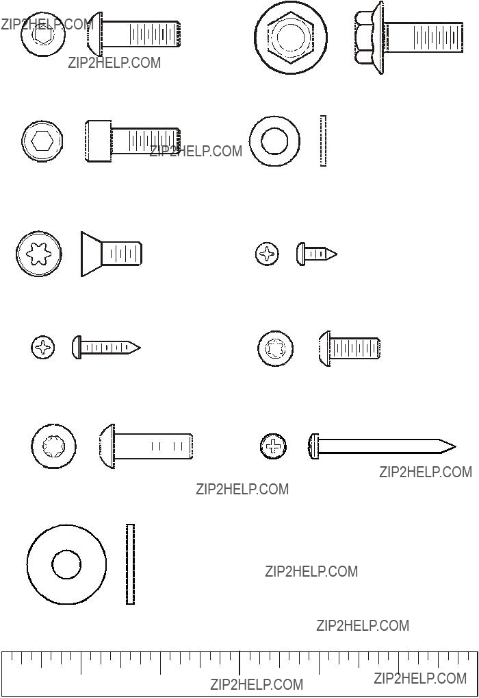
PARTS DESCRIPTION
This product is preconfigured to accept the addition of the Life Fitness Entertainment System. A POWER CABLE and COAXIAL CABLE have been
Route the POWER CABLE and COAXIAL CABLE alongside the MAIN WIRE HARNESS where applicable.
When installing the Life Fitness Entertainment System, refer to the 95Xer or 95Xez procedures stated in the Life Fitness Entertainment System installation instructions.
30)

IMPORTANT!
DO NOT DISCARD THE SHIP KIT LOCATED ON TOP OF THE PEDALS. ALL NECESSARY COMPONENTS NEEDED TO
COMPLETE THE INSTALLATION ARE LOCATED IN THE SHIP KIT.
IMPORTANT!
NE JETEZ PAS LE KIT PLAC?? SUR LE DESSUS DES P??DALE. IL CONTIENT TOUS LES ??L??MENTS
N??CESSAIRES POUR L'INSTALLATION.
1.Open the top of the shipping carton.
2.Remove the documentation packet.
3.Remove the shipping sleeve.
4.Remove excess packaging. Knock down the sides of the bottom tray and remove any corrugated shipping blocks.
5.Remove the HANDRAIL and set it aside.
6. Carefully cut the vertical bands securing the MONOCOLUMN (A) assembly to the base pads.
7. Remove the tape, foam packaging and support block located at the RECTANGULAR TUBE (B) and the FRAME (C).
8. With the help of another person, carefully raise the MONOCOLUMN (A) and insert the RECTANGULAR TUBE
(B) into the FRAME (C).
CAUTION: Do not pinch the WIRE HARNESSES or scratch the paint when inserting the MONOCOLUMN into the
FRAME.
Secure the MONOCOLUMN to the FRAME using one SCREW (5) and WASHER (6) from the front and two SCREWS (5) and WASHERS (6) from the side. Tighten the SCREWS to 20
9. Carefully cut the band securing the RIGHT CONTROL LINK HUB (R) to the base pad. Lift the RIGHT CONTROL LINK upward and align it onto RIGHT CONTROL LINK SHAFT (S).
NOTE: Be sure the bearing within the RIGHT CONTROL LINK HUB seats fully onto the stepped end of the RIGHT
CONTROL LINK SHAFT.
Secure the RIGHT CONTROL LINK HUB to the RIGHT CONTROL LINK SHAFT using one SCREW (5) and WASHER (30). Tighten the SCREWS to 20
Install one ENDCAP (31) onto the RIGHT CONTROL LINK HUB (E)
10.Repeat Step 9 to install the LEFT CONTROL LINK HUB.
11.Carefully tilt the unit upward from the rear and roll the unit
to the desired location for use.
12. Install the REAR STEP (2) using three BOLTS (1). Finger- tighten the BOLTS.
13. Install the HANDRAIL UPRIGHTS (3) using one BOLT (4)
on each HANDRAIL UPRIGHT. Position the mounting3 holes at the top of the HANDRAIL UPRIGHTS to face the  front of the unit. Tighten the BOLTS until snug.
S
R
30 5 31
2
1
4

14. Locate the CONSOLE BRACKET (7). Feed the
Feed the COAXIAL CABLE (K) and POWER CORD (L) leading from the top of the MONOCOLUMN (A) through the top of the CONSOLE BRACKET as shown. Secure the CONSOLE BRACKET to the MONOCOLUMN using six SCREWS (8). Tighten the SCREWS securely.
NOTE: If the entertainment option will not be used, carefully gather the COAXIAL CABLE (K) and POWER CORD (L) and insert them into the CONSOLE BRACKET.
15.Locate and insert the ACCESSORY TRAY (9) into the MONOCOLUMN (A) as shown. Secure the ACCESSORY TRAY to the CONSOLE BRACKET (7) using two SCREWS (10). Tighten the SCREWS securely. Do not over tighten the SCREWS.
16.Locate and position the DISPLAY CONSOLE (11) near the ACCESSORY TRAY (9). Connect all CONNECTORS (E & F) leading from the CONSOLE BRACKET (7) to the rear of the DISPLAY CONSOLE. Mount the DISPLAY CONSOLE using four SCREWS (12). Tighten the SCREWS securely. Do not over tighten the SCREWS.
17.Locate and attach the CONSOLE SUPPORT COVER (13) using two SCREWS (12). Tighten the SCREWS securely. Do not over tighten the SCREWS.
18.Locate and install the CONSOLE SUPPORT CAP (14) . Be sure the CONSOLE SUPPORT CAP snaps securely in place.
19.Locate and install one GROMMET (15) in each square hole between the yellow inserts in the BULLHORN MOUNTING BRACKETS (H).
20.Locate the HANDRAIL (16). Position the rear tubes of the HANDRAIL over the HANDRAIL UPRIGHTS (3) and lower the HANDRAIL onto the HANDRAIL UPRIGHTS. Carefully rest the front of the HANDRAIL against the MONOCOLUMN (A). Secure the HANDRAIL to the HANDRAIL UPRIGHTS using four SCREWS (17). Tighten the SCREWS securely.
21.Locate the LEFT and RIGHT BACK BULLHORN COVERS (18 & 19). Place the BACK BULLHORN COVERS between the HANDRAIL (16) and BULLHORN MOUNTING BRACKETS (H) as shown. Route the HEART RATE WIRES (M) from the HANDRAIL downward inside the BACK BULLHORN COVERS and to the front of the unit. Connect the HEART RATE WIRES to those leading from the front of the MONOCOLUMN. Be sure the CONNECTORS are fully seated.
22.Secure the front of the HANDRAIL (16) to the BULLHORN MOUNTING BRACKETS using four SCREWS (20). Tighten the SCREWS securely.
10
J
A
H
16
20
18
19
17
3
H
15 M

23.Tighten the three BOLTS of the REAR STEP (2) securely.
24.Tighten the two BOLTS of the HANDRAIL UPRIGHTS (3) securely.
25.Locate and install the USER ARMS (21 & 22) using three SCREWS (8) each. Tighten the SCREWS securely.
NOTE: Orient the USER ARMS so the bends at the HANDGRIPS face the front of the unit as shown.
26.Locate one FRONT ROCKER COVER (23). Position the RIGHT BACK BULLHORN COVER (18) over the user side of the ROCKER ARM SHAFT (N) making sure that it seats fully over the BULLHORN MOUNTING BRACKET (H). Place the FRONT ROCKER COVER over the opposite side of the ROCKER ARM SHAFT in the same manner. Secure the COVERS using two PHILLIPS PAN HEAD SCREWS (12). Tighten the SCREWS securely. Do not
SCREWS.
27.Locate and attach the RIGHT BULLHORN COVER (27) to the base of the BULLHORN using one SCREW (28). Tighten the SCREW securely. Do not
BULLHORN COVER.
21
22
8
23
 O
O


12 


 28
28 
 18
18
26 N

28.Locate one FRONT PIVOT ARM COVER (24) and one BACK PIVOT ARM COVER (25). Position the BACK PIVOT ARM COVER over the user side of the ROCKER ARM (P) making sure that it interlocks with the RIGHT BACK BULLHORN COVER (18). Place the FRONT PIVOT ARM COVER over the opposite side of the ROCKER ARM in the same manner. Secure the COVERS using two PHILLIPS PAN HEAD SCREWS (12). Tighten the SCREWS securely. Do not
29.Repeat steps 22 through 24 to install the LEFT ROCKER COVER (23), PIVOT ARM COVERS (24 & 25), and BULLHORN COVER (26).
NOTE: The left PIVOT ARM COVERS are reversed front and back. The SCREWS will be installed from the rear.
30.Locate the two FOOT COVERS (29). Align the COVERS with the ends of the STABILIZER BARS (Q). Insert the post on the underside of the FOOT COVERS into the mounting holes on the top of each STABILIZER. Press the FOOT COVERS firmly into position.
31.Position the unit into the desired location for use. Properly level the unit according to the instructions in the Operation Manual.
Physical Dimensions:


 18 24
18 24
25 P
12
Q
29

Ensure that all fasteners are tight.
Make sure the SUMMIT TRAINER is properly leveled and stable. (Refer to the Operation Manual)
Ensure that the Leveler Jam Nuts are tight. (Refer to the Operation Manual)
Read the entire Operation manual before using the Summit Trainer.
LISTE DES V??RIFICATIONS ?? EFFECTUER AVANT LA MISE EN MARCHE
V??rifiez si tous les dispositifs de fixation sont serr??s
V??rifiez si l'APPAREIL D'EXERCICE POLYVALENT est de niveau et stable.
V??rifiez si les
Lisez le manuel d'utilisation dans son int??gralit?? avant d'utiliser l'appareil d'exercice polyvalent.
Before attempting to operate your Total Body Trainer, it is imperative that you familiarize yourself with the contents of the Operation Manual. If your Total Body Trainer does not respond as described in the Operation Manual, contact the nearest Life Fitness service center as listed in the Operation Manual.
Life Fitness Customer Support Services
(800)
Prior to your call, please be sure you have located and noted the
MODEL NUMBER & SERIAL NUMBER.
The Model & Serial number information of your Life Fitness Total Body Trainer is listed on a label located on the rear stabilizer.
??2006 Life Fitness, a division of Brunswick Corporation. All rights reserved. Life Fitness is a trademark of Brunswick Corporation.