ThinkPad X200 Tablet and X201 Tablet
Hardware Maintenance Manual
ThinkPad X200 Tablet and X201 Tablet
Hardware Maintenance Manual

ThinkPad X200 Tablet and X201 Tablet
Hardware Maintenance Manual
Note
Before using this information and the product it supports, be sure to read the general information under ???Notices??? on page 193.
Fourth Edition (February 2010)
?? Copyright Lenovo 2008 , 2010 .
LENOVO products, data, computer software, and services have been developed exclusively at private expense and are sold to governmental entities as commercial items as defined by 48 C.F.R. 2.101 with limited and restricted rights to use, reproduction and disclosure.
LIMITED AND RESTRICTED RIGHTS NOTICE: If products, data, computer software, or services are delivered pursuant a General Services Administration ???GSA??? contract, use, reproduction, or disclosure is subject to restrictions set forth in Contract No.

Contents
About this manual. . . . . . . . . . . . v
Chapter 1. Safety information . . . . . 1
Handling devices that are sensitive to electrostatic discharge. . . . . . . . . . . . . . . . . . 3
iv ThinkPad X200 Tablet and X201 Tablet Hardware Maintenance Manual
About this manual
This manual contains service and reference information for the following ThinkPad?? products.
Use this manual along with the advanced diagnostic tests to troubleshoot problems.
Important:
This manual is intended only for trained service technicians who are familiar with ThinkPad products. Use this manual along with the advanced diagnostic tests to troubleshoot problems effectively.
Before servicing a ThinkPad product, be sure to read all the information under Chapter 1 ???Safety information??? on page 1 and Chapter 2 ???Important service information??? on page 21.
vi ThinkPad X200 Tablet and X201 Tablet Hardware Maintenance Manual

Chapter 1. Safety information
This chapter presents following safety information that you need to be familiar with before you service a ThinkPad Notebook.
??????General safety??? on page 1
??????Electrical safety??? on page 2
??????Safety inspection guide??? on page 3
??????Handling devices that are sensitive to electrostatic discharge??? on page 3
??????Grounding requirements??? on page 4
??????Safety notices (multilingual translations)??? on page 4
??????Laser compliance statement (multilingual translations)??? on page
General safety
Follow these rules to ensure general safety:
???Observe good housekeeping in the area of the machines during and after maintenance.
???When lifting any heavy object:
1.Make sure that you can stand safely without slipping.
2.Distribute the weight of the object equally between your feet.
3.Use a slow lifting force. Never move suddenly or twist when you attempt to lift.
4.Lift by standing or by pushing up with your leg muscles; this action removes the strain from the muscles in your back. Do not attempt to lift any object that weighs more than 16 kg (35 lb) or that you think is too heavy for you.
???Do not perform any action that causes hazards to the customer, or that makes the equipment unsafe.
???Before you start the machine, make sure that other service technicians and the customer's personnel are not in a hazardous position.
???Place removed covers and other parts in a safe place, away from all personnel, while you are servicing the machine.
???Keep your toolcase away from walk areas so that other people will not trip over it.
???Do not wear loose clothing that can be trapped in the moving parts of a machine. Make sure that your sleeves are fastened or rolled up above your elbows. If your hair is long, fasten it.
???Insert the ends of your necktie or scarf inside clothing or fasten it with a nonconductive clip, about 8 centimeters (3 inches) from the end.
???Do not wear jewelry, chains,
Attention: Metal objects are good electrical conductors.
???Wear safety glasses when you are hammering, drilling, soldering, cutting wire, attaching springs, using solvents, or working in any other conditions that might be hazardous to your eyes.
???After service, reinstall all safety shields, guards, labels, and ground wires. Replace any safety device that is worn or defective.
???Reinstall all covers correctly before returning the machine to the customer.
???Fan louvers on the machine help to prevent overheating of internal components. Do not obstruct fan louvers or cover them with labels or stickers.

Electrical safety
Observe the following rules when working on electrical equipment.
Important:
Use only approved tools and test equipment. Some hand tools have handles covered with a soft material that does not insulate you when working with live electrical currents.
Many customers have, near their equipment, rubber floor mats that contain small conductive fibers to decrease electrostatic discharges. Do not use this type of mat to protect yourself from electrical shock.
???Find the room emergency
???Do not work alone under hazardous conditions or near equipment that has hazardous voltages.
???Disconnect all power before:
???Performing a mechanical inspection
???Working near power supplies
???Removing or installing main units
???Before you start to work on the machine, unplug the power cord. If you cannot unplug it, ask the customer to
???If you need to work on a machine that has exposed electrical circuits, observe the following precautions:
???Ensure that another person, familiar with the
Attention: Another person must be there to switch off the power, if necessary.
???Use only one hand when working with
Attention: An electrical shock can occur only when there is a complete circuit. By observing the above rule, you may prevent a current from passing through your body.
???When using testers, set the controls correctly and use the approved probe leads and accessories for that tester.
???Stand on suitable rubber mats (obtained locally, if necessary) to insulate you from grounds such as metal floor strips and machine frames.
Observe the special safety precautions when you work with very high voltages; Instructions for these precautions are in the safety sections of maintenance information. Use extreme care when measuring high voltages.
???Regularly inspect and maintain your electrical hand tools for safe operational condition.
???Do not use worn or broken tools and testers.
???Never assume that power has been disconnected from a circuit. First, check that it has been powered off.
???Always look carefully for possible hazards in your work area. Examples of these hazards are moist floors, nongrounded power extension cables, power surges, and missing safety grounds.
???Do not touch live electrical circuits with the reflective surface of a plastic dental mirror. The surface is conductive; such touching can cause personal injury and machine damage.
???Do not service the following parts with the power on when they are removed from their normal operating places in a machine:
???Power supply units
???Pumps
???Blowers and fans
???Motor generators
???Similar units to listed above
This practice ensures correct grounding of the units.
??? If an electrical accident occurs:
2 ThinkPad X200 Tablet and X201 Tablet Hardware Maintenance Manual
???Use caution; do not become a victim yourself.
???Switch off power.
???Send another person to get medical aid.
Safety inspection guide
The purpose of this inspection guide is to assist you in identifying potentially unsafe conditions. As each machine was designed and built, required safety items were installed to protect users and service technicians from injury. This guide addresses only those items. You should use good judgment to identify potential safety hazards due to attachment of
If any unsafe conditions are present, you must determine how serious the apparent hazard could be and whether you can continue without first correcting the problem.
Consider these conditions and the safety hazards they present:
???Electrical hazards, especially primary power (primary voltage on the frame can cause serious or fatal electrical shock)
???Explosive hazards, such as a damaged CRT face or a bulging capacitor
???Mechanical hazards, such as loose or missing hardware
To determine whether there are any potentially unsafe conditions, use the following checklist at the beginning of every service task. Begin the checks with the power off, and the power cord disconnected.
Checklist:
1.Check exterior covers for damage (loose, broken, or sharp edges).
2.Power off the computer. Disconnect the power cord.
3.Check the power cord for:
a.A
b.The power cord should be the type specified in the parts list.
c.Insulation must not be frayed or worn.
4.Check for cracked or bulging batteries.
5.Remove the cover.
6.Check for any obvious
7.Check inside the unit for any obvious unsafe conditions, such as metal filings, contamination, water or other liquids, or signs of fire or smoke damage.
8.Check for worn, frayed, or pinched cables.
9.Check that the
Handling devices that are sensitive to electrostatic discharge
Any computer part containing transistors or integrated circuits (ICs) should be considered sensitive to electrostatic discharge (ESD.) ESD damage can occur when there is a difference in charge between objects. Protect against ESD damage by equalizing the charge so that the machine, the part, the work mat, and the person handling the part are all at the same charge.
Chapter 1. Safety information 3
Notes:
1.Use
2.Make sure that the ESD protective devices you use have been certified (ISO 9000) as fully effective.
When handling
???Keep the parts in protective packages until they are inserted into the product.
???Avoid contact with other people.
???Wear a grounded wrist strap against your skin to eliminate static on your body.
???Prevent the part from touching your clothing. Most clothing is insulative and retains a charge even when you are wearing a wrist strap.
???Use a grounded work mat to provide a
???Select a grounding system, such as those listed below, to provide protection that meets the specific service requirement.
Note:
The use of a grounding system to guard against ESD damage is desirable but not necessary.
???Attach the ESD ground clip to any frame ground, ground braid, or
???When working on a
???Use the round ground prong of the ac plug on
Grounding requirements
Electrical grounding of the computer is required for operator safety and correct system function. Proper grounding of the electrical outlet can be verified by a certified electrician.
Safety notices (multilingual translations)
The safety notices in this section are provided in the following languages:
???English
???Arabic
???French
???German
???Hebrew
???Japanese
???Korean
???Spanish
DANGER
4 ThinkPad X200 Tablet and X201 Tablet Hardware Maintenance Manual
Before the computer is powered on after FRU replacement, make sure all screws, springs, and other small parts are in place and are not left loose inside the computer. Verify this by shaking the computer and listening for rattling sounds. Metallic parts or metal flakes can cause electrical shorts.
DANGER
Some standby batteries contain a small amount of nickel and cadmium. Do not disassemble a standby battery, recharge it, throw it into fire or water, or
in ignition or explosion of the battery.
DANGER
The battery pack contains small amounts of nickel. Do not disassemble it, throw it into fire or water, or
DANGER
The lithium battery can cause a fire, an explosion, or a severe burn. Do not recharge it, remove its polarized connector, disassemble it, heat it above 100??C (212??F), incinerate it, or expose its cell contents to water. Dispose of the battery as required by local ordinances or regulations. Use only the battery in the appropriate parts listing. Use of an incorrect battery can result in ignition or explosion of the battery.
DANGER
If the LCD breaks and the fluid from inside the LCD gets into your eyes or on your hands, immediately wash the affected areas with water for at least 15 minutes. Seek medical care if any symptoms from the fluid are present after washing.
DANGER
To avoid shock, do not remove the plastic cover that protects the lower part of the inverter card.
Chapter 1. Safety information 5
DANGER
Though the main batteries have low voltage, a shorted or grounded battery can produce enough current to burn personnel or combustible materials.
DANGER
Unless hot swap is allowed for the FRU being replaced, do as follows before removing it: power off the computer, unplug all power cords from electrical outlets, remove the battery pack, and disconnect any interconnecting cables.
6 ThinkPad X200 Tablet and X201 Tablet Hardware Maintenance Manual

Chapter 1. Safety information 7
PERIGO
Antes de ligar o computador ap??s a substitui????o da FRU,
PERIGO
Algumas baterias reserva cont??m uma pequena quantidade de n??quel e c??dmio. N??o desmonte uma bateria reserva,
PERIGO
O pacote da bateria cont??m uma pequena quantidade de n??quel. N??o o desmonte,
PERIGO
8 ThinkPad X200 Tablet and X201 Tablet Hardware Maintenance Manual
A bateria de l??tio pode causar inc??ndio, explos??o ou graves queimaduras. N??o a recarregue, remova seu conector polarizado,
PERIGO
Se o LCD quebrar e o fluido de dentro dele entrar em contato com seus olhos ou com suas m??os, lave as ??reas afetadas imediatamente com ??gua durante pelo menos 15 minutos. Procure cuidados m??dicos se algum sintoma causado pelo fluido surgir ap??s a lavagem.
PERIGO
Para evitar choque el??trico, n??o remova a capa pl??stica que protege a parte inferior da placa inversora.
PERIGO
Embora as principais baterias possuam baixa voltagem, uma bateria em
PERIGO
A menos que uma hot swap seja permitida para a FRU que est?? sendo substitu??da, fa??a o seguinte antes de
DANGER
Avant de remettre l'ordinateur sous tension apr??s remplacement d'une unit?? en client??le, v??rifiez que tous les ressorts, vis et autres pi??ces sont bien en place et bien fix??es. Pour ce faire, secouez l'unit?? et
Chapter 1. Safety information 9

DANGER
Certaines batteries de secours contiennent du nickel et du cadmium. Ne les d??montez pas, ne les rechargez pas, ne les exposez ni au feu ni ?? l'eau. Ne les mettez pas en
DANGER
La batterie contient du nickel. Ne la d??montez pas, ne l'exposez ni au feu ni ?? l'eau. Ne la mettez pas en
DANGER
La pile de sauvegarde contient du lithium. Elle pr??sente des risques d'incendie, d'explosion ou de br??lures graves. Ne la rechargez pas, ne retirez pas son connecteur polaris?? et ne la d??montez pas. Ne l'exposez pas ?? une temperature sup??rieure ?? 100??C, ne la faites pas br??ler et n'en exposez pas le contenu ?? l'eau. Mettez la pile au rebut conform??ment ?? la r??glementation en vigueur. Une pile inappropri??e risque de prendre feu ou d'exploser.
DANGER
Si le panneau d'affichage ?? cristaux liquides se brise et que vous recevez dans les yeux ou sur les mains une partie du fluide,
DANGER
Afin d'??viter tout risque de choc ??lectrique, ne retirez pas le cache en plastique prot??geant la partie inf??rieure de la carte d'alimentation.
10 ThinkPad X200 Tablet and X201 Tablet Hardware Maintenance Manual
DANGER
Bien que le voltage des batteries principales soit peu ??lev??, le
DANGER
Si le remplacement ?? chaud n'est pas autoris?? pour l'unit?? rempla??able sur site que vous remplacez, proc??dez comme suit avant de retirer l'unit?? : mettez l'ordinateur hors tension, d??branchez tous les cordons d'alimentation des prises de courant, retirez le bloc de batterie et d??connectez tous les c??bles d'interconnexion.
VORSICHT
Bevor nach einem
VORSICHT
Die Bereitschaftsbatterie, die sich unter dem Diskettenlaufwerk befindet, kann geringe Mengen Nickel und Cadmium enthalten. Sie darf nur durch die Verkaufsstelle oder den IBM Kundendienst ausgetauscht werden. Sie darf nicht zerlegt, wiederaufgeladen, kurzgeschlossen, oder Feuer oder Wasser ausgesetzt werden. Die Batterie kann schwere Verbrennungen oder Ver??tzungen verursachen. Bei der Entsorgung die ??rtlichen Bestimmungen f??r Sonderm??ll beachten. Beim Ersetzen der
VORSICHT
Akkus enthalten geringe Mengen von Nickel. Sie d??rfen nicht zerlegt, wiederaufgeladen, kurzgeschlossen, oder Feuer oder Wasser ausgesetzt werden. Bei der Entsorgung die ??rtlichen Bestimmungen f??r Sonderm??ll beachten. Beim Ersetzen der Batterie nur Batterien des Typs verwenden, der in der Ersatzteilliste aufgef??hrt ist. Der Einsatz falscher Batterien kann zu Entz??ndung oder Explosion f??hren.
VORSICHT
Chapter 1. Safety information 11
Die Systembatterie ist eine Lithiumbatterie. Sie kann sich entz??nden, explodieren oder schwere Verbrennungen hervorrufen. Batterien dieses Typs d??rfen nicht aufgeladen, zerlegt, ??ber 100 C erhitzt oder verbrannt werden. Auch darf ihr Inhalt nicht mit Wasser in Verbindung gebracht oder der zur richtigen Polung angebrachte Verbindungsstecker entfernt werden. Bei der Entsorgung die ??rtlichen Bestimmungen f??r Sonderm??ll beachten. Beim Ersetzen der Batterie nur Batterien des Typs verwenden, der in der Ersatzteilliste aufgef??hrt ist. Der Einsatz falscher Batterien kann zu Entz??ndung oder Explosion f??hren.
VORSICHT
Die Leuchtstoffr??hre im
VORSICHT
Aus Sicherheitsgr??nden die Kunststoffabdeckung, die den unteren Teil der Spannungswandlerplatine umgibt, nicht entfernen.
VORSICHT
Obwohl Hauptbatterien eine niedrige Spannung haben, k??nnen sie doch bei Kurzschlu?? oder Erdung genug Strom abgeben, um brennbare Materialien zu entz??nden oder Verletzungen bei Personen hervorzurufen.
VORSICHT
Wenn ein Austausch der FRU bei laufendem Betrieb nicht erlaubt ist, gehen Sie beim Austausch der FRU wie folgt vor: Schalten Sie den Computer aus, ziehen Sie alle Netzkabel von den Netzsteckdosen ab, entfernen Sie den Akku und ziehen Sie alle miteinander verbundenen Kabel ab.
12 ThinkPad X200 Tablet and X201 Tablet Hardware Maintenance Manual
Chapter 1. Safety information 13

14 ThinkPad X200 Tablet and X201 Tablet Hardware Maintenance Manual

Chapter 1. Safety information 15
16 ThinkPad X200 Tablet and X201 Tablet Hardware Maintenance Manual
Antes de encender el sistema despues de sustituir una FRU, compruebe que todos los tornillos, muelles y dem??s piezas peque??as se encuentran en su sitio y no se encuentran sueltas dentro del sistema. Compru??belo agitando el sistema y escuchando los posibles ruidos que provocar??an. Las piezas met??licas pueden causar cortocircuitos el??ctricos.
Algunas bater??as de reserva contienen una peque??a cantidad de n??quel y cadmio. No las desmonte, ni recargue, ni las eche al fuego o al agua ni las cortocircuite. Des??chelas tal como dispone la normativa local. Utilice s??lo bater??as que se encuentren en la lista de piezas. La utilizaci??n de una bater??a no apropiada puede provocar la ignici??n o explosi??n de la misma.
Las bater??as contienen peque??as cantidades de n??quel. No las desmonte, ni recargue, ni las eche al fuego o al agua ni las cortocircuite. Des??chelas tal como dispone la normativa local. Utilice s??lo bater??as que se encuentren en la lista de piezas al sustituir la bater??a. La utilizaci??n de una bater??a no apropiada puede provocar la ignici??n o explosi??n de la misma.
Chapter 1. Safety information 17

La bater??a de repuesto es una bater??a de litio y puede provocar incendios, explosiones o quemaduras graves. No la recargue, ni quite el conector polarizado, ni la desmonte, ni caliente por encima de los 100??C (212??F), ni la incinere ni exponga el contenido de sus celdas al agua. Des??chela tal como dispone la normativa local.
Si la LCD se rompe y el fluido de su interior entra en contacto con sus ojos o sus manos, lave inmediatamente las ??reas afectadas con agua durante 15 minutos como m??nimo. Obtenga atenci??n medica si se presenta alg??n s??ntoma del fluido despues de lavarse.
Para evitar descargas, no quite la cubierta de pl??stico que rodea la parte baja de la tarjeta invertida.
Aunque las bater??as principales tienen un voltaje bajo, una bater??a cortocircuitada o con contacto a tierra puede producir la corriente suficiente como para quemar material combustible o provocar quemaduras en el personal.
Salvo que se permita el intercambio en caliente para la unidad sustituible localmente, realice lo siguiente antes de extraerla: apague el sistema, desconecte todos los cables de alimentaci??n de las tomas de alimentaci??n el??ctrica, extraiga la bater??a y desconecte los cables de interconexi??n.
18 ThinkPad X200 Tablet and X201 Tablet Hardware Maintenance Manual
Chapter 1. Safety information 19
20 ThinkPad X200 Tablet and X201 Tablet Hardware Maintenance Manual
Chapter 2. Important service information
This chapter presents following important service information that applies to all machine types supported by this manual:
??????Strategy for replacing FRUs??? on page 21
??????Strategy for replacing a hard disk drive??? on page 22
??????Important notice for replacing a system board??? on page 22
??????How to use error message??? on page 22
??????Strategy for replacing FRUs for CTO, CMV, and GAV??? on page 22
??????Product definition??? on page 22
??????FRU identification for CTO, CMV, and GAV products??? on page 23
Important:
BIOS and device driver fixes are
System Disassembly/Reassembly videos that show the FRU removals or replacements for the Lenovo?? authorized service technicians are available in the following support site: http://www.lenovoservicetraining.com.
Advise customers to contact the Customer Support Center at
Customers in Canada should call the Customer Support Center at
Strategy for replacing FRUs
Before replacing parts:
Make sure that all software fixes, drivers, and BIOS downloads are installed before replacing any FRUs listed in this manual.
After a system board is replaced, ensure that the latest BIOS is loaded to the system board before completing the service action.
To download software fixes, drivers, and BIOS, do as follows:
1.Go to http://www.lenovo.com/support.
2.Enter the product number of the computer or press
3.Select Downloads and drivers.
4.Follow the directions on the screen and install the necessary software.
Use the following strategy to prevent unnecessary expense for replacing and servicing FRUs:
???If you are instructed to replace a FRU but the replacement does not correct the problem, reinstall the original FRU before you continue.

???Some computers have both a processor board and a system board. If you are instructed to replace either the processor board or the system board, and replacing one of them does not correct the problem, reinstall that board, and then replace the other one.
???If an adapter or a device consists of more than one FRU, any of the FRUs may be the cause of the error. Before replacing the adapter or device, remove the FRUs, one by one, to see if the symptoms change. Replace only the FRU that changed the symptoms.
Attention: The setup configuration on the computer you are servicing may have been customized. Running Automatic Configuration may alter the settings. Note the current configuration settings (using the View Configuration option); then, when service has been completed, verify that those settings remain in effect.
Strategy for replacing a hard disk drive
Always try to run a
Attention: The drive startup sequence in the computer you are servicing may have been changed. Be extremely careful during write operations such as copying, saving, or formatting. If you select an incorrect drive, data or programs can be overwritten.
Important notice for replacing a system board
Some components mounted on a system board are very sensitive. Improper handling of a system board can cause damage to those components, and may cause a system malfunction.
Attention: When handling a system board:
???Do not drop a system board or apply any excessive force to it.
???Avoid rough handling of any kind.
???Avoid bending a system board and hard pushing to prevent cracking at each BGA (Ball Grid Array) chipset.
How to use error message
Use the error codes displayed on the screen to diagnose failures. If more than one error code is displayed, begin the diagnosis with the first error code. Whatever causes the first error code may also cause false error codes. If no error code is displayed, see whether the error symptom is listed in the
Strategy for replacing FRUs for CTO, CMV, and GAV
Product definition
Dynamic Configure To Order (CTO)
This provides the ability for a customer to configure an IBM?? or a Lenovo solution from an eSite, and have this configuration sent to fulfillment, where it is built and shipped directly to the customer. The machine label, Product Entitlement Warehouse (PEW), eSupport, and the HMM will load these products as the
Custom Model Variant (CMV)
This is a unique configuration that has been negotiated between IBM or Lenovo and the customer. A unique
is a special bid offering. Therefore, it is NOT generally announced.
22 ThinkPad X200 Tablet and X201 Tablet Hardware Maintenance Manual
???The MTM portion of the machine label is the
???The PEW record is the
???eSupport will show both the CTO and CMV machine type models (Example:
???The HMM will have the
General Announce Variant (GAV)
This is a standard model (fixed configuration). GAVs are announced and offered to all customers. The MTM portion of the machine label is a
FRU identification for CTO, CMV, and GAV products
There are three information resources to identify which FRUs are used to support CTO, CMV, and GAV products. These sources are PEW, eSupport, and the HMM.
Using PEW
???PEW is the primary source for identifying FRU part numbers and FRU descriptions for the key commodities for CTO, CMV and GAV products at a MT - serial number level. An example of key commodities are hard disk drives, system boards, microprocessors, Liquid Crystal Displays (LCDs), and memory.
???Remember, all CTO and CMV products are loaded in PEW under the
???PEW can be accessed at the following Web site:
Select Warranty lookup. Input the MT and the Serial number and the list of key commodities will be returned in the PEW record under COMPONENT INFORMATION.
???Business Partners using Eclaim will access PEW when performing Entitlement Lookup. Business Partners will enter Loc ID, MT and Serial, and the key commodities will be returned in the Eclaim record under SYSTEM DETAILS.
???Authorized IBM Business Partners can access Eclaim at the following Web site: https://wca.eclaim.com.
Using eSupport
For Key Commodities (Examples - hard disk drive, system board, microprocessor, LCD, and memory)
???eSupport can be used to view the list of key commodities built in a particular machine serial (this is the same record found in PEW).
???eSupport can be accessed at the following Web site: http://www.lenovo.com/support.
???To view the key commodities, click on PARTS INFORMATION, then PARTS LOOKUP. Type in the model type and serial number. The key commodities will be returned in the eSupport record under PARTS
SHIPPED WITH YOUR SYSTEM.
For the Remaining FRUs (the complete list of FRUs at the MT Model level)
???eSupport can be used to view the complete list of FRUs for a machine type and model.
???To view the complete list of FRUs, type in the machine type and model (Example:
Chapter 2. Important service information 23
select SERVICE PARTS. Under ???Parts Information by Date??? select SYSTEM SERVICE PARTS. The list of service parts by description, with applicable machine type model and FRU will be displayed.
Using the HMM
For Key Commodities (Examples - hard disk drive, system board, microprocessor, LCD, and memory)
Use the HMM as a
24 ThinkPad X200 Tablet and X201 Tablet Hardware Maintenance Manual

Chapter 3. General checkout
This chapter presents following information:
??????What to do first??? on page 25
??????Checkout guide??? on page 26
??????Diagnostics using
??????Lenovo ThinkVantage Toolbox (Lenovo System Toolbox)??? on page 29
???
???
??????Power system checkout??? on page 31
The descriptions in this chapter apply to any ThinkPad model that supports the
Before you go to the checkout guide, be sure to read the following important notes.
Important notes:
???Only certified trained personnel should service the computer.
???Before replacing any FRU, read the entire page on removing and replacing FRUs.
???When you replace FRUs, use new
???Be extremely careful during such write operations as copying, saving, or formatting. Drives in the computer that you are servicing sequence might have been altered. If you select an incorrect drive, data or programs might be overwritten.
???Replace a FRU only with another FRU of the correct model. When you replace a FRU, make sure that the model of the machine and the FRU part number are correct by referring to the FRU parts list.
???A FRU should not be replaced because of a single, unreproducible failure. Single failures can occur for a variety of reasons that have nothing to do with a hardware defect, such as cosmic radiation, electrostatic discharge, or software errors. Consider replacing a FRU only when a problem recurs. If you suspect that a FRU is defective, clear the error log and run the test again. If the error does not recur, do not replace the FRU.
???Be careful not to replace a nondefective FRU.
What to do first
When you do return a FRU, you must include the following information in the parts exchange form or parts return form that you attach to it:
1.Name and phone number of service technician
2.Date of service
3.Date on which the machine failed
4.Date of purchase
5.Failure symptoms, error codes appearing on the display, and beep symptoms
6.Procedure index and page number in which the failing FRU was detected
7.Failing FRU name and part number
8.Machine type, model number, and serial number
9.Customer's name and address
Note for warranty: During the warranty period, the customer may be responsible for repair costs if the computer damage was caused by misuse, accident, modification, unsuitable physical or operating environment, or improper maintenance by the customer.
Following is a list of some common items that are not covered under warranty and some symptoms that might indicate that the system was subjected to stress beyond normal use.
Before checking problems with the computer, determine whether the damage is covered under the warranty by referring to the following list:
The following are not covered under warranty:
???LCD panel cracked from the application of excessive force or from being dropped
???Scratched (cosmetic) parts
???Distortion, deformation, or discoloration of the cosmetic parts
???Plastic parts, latches, pins, or connectors that have been cracked or broken by excessive force
???Damage caused by liquid spilled into the system
???Damage caused by the improper insertion of a PC Card or the installation of an incompatible card
???Improper disc insertion or use of an optical drive
???Diskette drive damage caused by pressure on the diskette drive cover, foreign material in the drive, or the insertion of a diskette with multiple labels
???Damaged or bent diskette eject button
???Fuses blown by attachment of a nonsupported device
???Forgotten computer password (making the computer unusable)
???Sticky keys caused by spilling a liquid onto the keyboard
???Use of an incorrect ac adapter on laptop products
The following symptoms might indicate damage caused by nonwarranted activities:
???Missing parts might be a symptom of unauthorized service or modification.
???If the spindle of a hard disk drive becomes noisy, it may have been subjected to excessive force, or dropped.
Checkout guide
Use the following procedures as a guide in identifying and correcting problems with the ThinkPad Notebook.
Note: The diagnostic tests are intended to test only ThinkPad products. The use of
1.Identify the failing symptoms in as much detail as possible.
2.Verify the symptoms. Try to
Diagnostics using
The ThinkPad Notebook has a test program called
Note:
To create the
For some possible configurations of the computer,
To enter BIOS Setup Utility, do as follows:
1. Turn on the computer.
26 ThinkPad X200 Tablet and X201 Tablet Hardware Maintenance Manual

2. When the ThinkPad logo comes up, immediately press F1 to enter the BIOS Setup Utility.
Note: If a supervisor password has been set by the customer, BIOS Setup Utility menu appears after the password is entered. You can start the utility by pressing Enter instead of entering the supervisor password; however, you cannot change the parameters that are protected by the supervisor password.
On the BIOS Setup Utility screen, press F9, Enter, F10, and then Enter.
Note: When you initialize the computer configuration, some devices are disabled, such as the serial port. If you test one of these devices, you will need to enable it by using Configuration utility for DOS. The utility is available on the following Web site:
Testing the computer
Note: The
To run the test, do as follows:
1.Turn off the computer.
2.Make sure that the internal optical drive that is supported as a startup device is attached to the computer.
3.Turn on the computer. If the computer cannot be powered on, go to ???Power system checkout??? on page 31, and check the power sources.
If an error code appears, go to
4.When the ThinkPad logo comes up, immediately press F12 to enter the Boot Menu.
5.Insert the
6.Press cursor keys to select ATAPI CDx (x: 0, 1, ...) and then press Enter.
7.Follow the instructions on the screen.
8.The main panel of
9.Select Diagnostics with the arrow keys, and press Enter.
Note: You can select an item not only with the arrow keys, but also with the TrackPoint?? pointer. Instead of pressing Enter, click the left button.
A
Note:
The options on the test menu are as follows:
Chapter 3. General checkout 27

Notes:
??? In the Keyboard test in Interactive Tests, the Fn key should be held down for at least 2 seconds; otherwise, it cannot be sensed.
??? Video Adapter test supports only the LCD display on the ThinkPad Notebook. If you have an external monitor attached to your computer, detach it before running
??? To test Digital Signature Chip, the security chip must be set to Active.
??? To test Serial Ports or Parallel Ports, the ThinkPad Notebook must be attached to the docking station.
10.Run the applicable function test.
11.Follow the instructions on the screen. If there is a problem,
12.To exit the test, select Quit ??? Exit Diag. To cancel the test, press Esc.
Note: After running
Detecting system information with
28 ThinkPad X200 Tablet and X201 Tablet Hardware Maintenance Manual

Lenovo ThinkVantage Toolbox (Lenovo System Toolbox)
Lenovo ThinkVantage?? Toolbox (Lenovo System Toolbox in Windows Vista?? and Windows?? XP) is a diagnostic program that works through the Windows operating system. It enables you to view symptoms of computer problems and solutions for them, and includes automatic notification when action is required, computing assistance, advanced diagnostics, and diagnostic history.
Note:
The latest Lenovo ThinkVantage Toolbox (Lenovo System Toolbox) is available at the following Web site: http://www.lenovo.com/support.
To install the latest Lenovo ThinkVantage Toolbox (Lenovo System Toolbox) on the computer, follow the instructions on the Web site.
To run this program, do as follows:
Windows 7:
While the Windows operating system is running, press the ThinkVantage button.
You can also run this program as either of the following:
???Click Start > All Programs >Lenovo ThinkVantage Tools >System Health and Diagnostics.
???Click Start >Control Panel >System and Security >Lenovo's System Health and Diagnostics.
Windows Vista and Windows XP:
Click Start >All Programs >Lenovo Services >Lenovo System Toolbox.
Follow the instructions on the screen. Lenovo ThinkVantage Toolbox (Lenovo System Toolbox) also has problem determination aids that determine software and usage problems.
For additional information about this program, see the Help for the program.
In some models of ThinkPad Notebook,
Select one of the categories listed below to display symptoms and solutions:
???Check System Health
???System and Device Tests
???Lenovo Troubleshooting Center
???System Reports
???Updates and Support
In some models of ThinkPad Notebook, the Rescue and Recovery?? workspace enables you to run the
To run the test, click ???Run Diagnostics??? on the Rescue and Recovery main screen.
FRU tests
The following table shows the test for each FRU.
Chapter 3. General checkout 29

Table 1. FRU tests
30 ThinkPad X200 Tablet and X201 Tablet Hardware Maintenance Manual
Power system checkout
To verify a symptom, do the following:
1.Turn off the computer.
2.Remove the battery pack.
3.Connect the ac adapter.
4.Check that power is supplied when you turn on the computer.
5.Turn off the computer.
6.Disconnect the ac adapter and install the charged battery pack.
7.Check that the battery pack supplies power when you turn on the computer.
If you suspect a power problem, see the appropriate one of the following power supply checkouts:
??????Checking the ac adapter??? on page 31
??????Checking operational charging??? on page 31
??????Checking the battery pack??? on page 32
??????Checking the backup battery??? on page 32
Checking the ac adapter
You are here because the computer fails only when the ac adapter is used.
???If the power problem occurs only when the ThinkPad X200 UltraBase is used, replace the UltraBase.
???If the
???If the computer does not charge during operation, go to ???Checking operational charging??? on page 31.
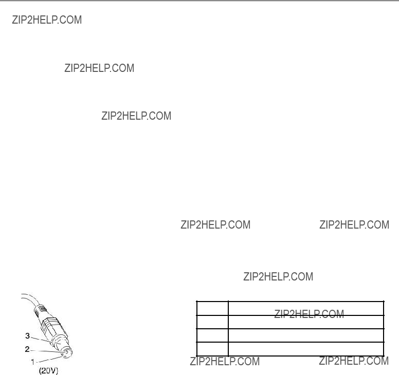
To check the ac adapter, do the following:
1.Unplug the ac adapter cable from the computer.
2.Measure the output voltage at the plug of the ac adapter cable. See the following figure:
1 +20
2 0
3 Ground
Note: Output voltage of pin no.2 of the ac adapter may different from the one you are servicing.
3.If the voltage is not correct, replace the ac adapter.
4.If the voltage is acceptable, do the following:
???Replace the system board.
???If the problem persists, go to ???FRU tests??? on page 29.
Note: Noise from the ac adapter does not always indicate a defect.
Checking operational charging
To check whether the battery charges properly during operation, use a discharged battery pack or a battery pack that has less than 50% of the total power remaining when installed in the computer.
Chapter 3. General checkout 31
Perform operational charging. If the battery status indicator or icon does not turn on, remove the battery pack and let it return to room temperature. Reinstall the battery pack. If the charge indicator or icon still does not turn on, replace the battery pack.
If the charge indicator still does not turn on, replace the system board. Then reinstall the battery pack. If it is still not charged, go to the next section.
Checking the battery pack
Battery charging does not start until the Power Manager Battery Gauge shows that less than 96% of the total power remains; under this condition the battery pack can charge to 100% of its capacity. This protects the battery pack from being overcharged or from having a shortened life.
To check your battery, move your cursor to the Power Manager Battery Gauge icon in the icon tray of the Windows taskbar and wait for a moment (but do not click), and the percentage of battery power remaining is displayed. To get detailed information about the battery,
Note: If the battery pack becomes hot, it may not be able to charge. Remove it from the computer and leave it at room temperature for a while. After it cools down, reinstall and recharge it.
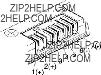
To check the battery pack, do the following:
1.Power off the computer.
2.Remove the battery pack and measure the voltage between battery terminals 1 (+) and 7
3.If the voltage is less than +11.0 V dc, the battery pack has been discharged.
Note: Recharging will take at least 3 hours, even if the indicator does not turn on. If the voltage is still less than +11.0 V dc after recharging, replace the battery.
4.If the voltage is more than +11.0 V dc, measure the resistance between battery terminals 5 and 7. The resistance must be 4 to 30 K ??. If the resistance is not correct, replace the battery pack. If the resistance is correct, replace the system board.
Checking the backup battery
Do the following:
1.Power off the computer, and unplug the ac adapter from it.
2.Turn the computer upside down.
3.Remove the battery pack (see ???1020 Battery pack??? on page 63).
4.Remove the backup battery (see ???1090 Backup battery??? on page 76).
5.Measure the voltage of the backup battery. See the following figure.
32 ThinkPad X200 Tablet and X201 Tablet Hardware Maintenance Manual
???If the voltage is correct, replace the system board.
???If the voltage is not correct, replace the backup battery.
???If the backup battery discharges quickly after replacement, replace the system board.
Chapter 3. General checkout 33
34 ThinkPad X200 Tablet and X201 Tablet Hardware Maintenance Manual
Chapter 4. Related service information
This chapter presents following information:
??????Restoring the factory contents by using Product Recovery discs??? on page 35
??????Restoring the factory contents by using Recovery Disc Set??? on page 36
??????Power management??? on page 39
???
Service Web site:
When the latest maintenance diskette and the system program service diskette become available, they will be posted on http://www.lenovo.com/spm.
Restoring the factory contents by using Product Recovery discs
When the hard disk drive (HDD) or solid state drive (SSD) is replaced because of a failure, no Product Recovery program is on the new drive. In this case, you must use the recovery discs for the computer. Order the recovery discs and the drive at the same time so that you can recover the new drive with the
To install the factory contents by using Product Recovery discs, do the following:
Note: Recovery takes several hours. The length of time depends on the method you use. If you use recovery discs, recovery takes at least five hours.
1.Insert the bootable Start Recovery Disc into the DVD drive.
2.Select your language and click Next.
3.Read the license. If you agree with the terms, select I accept these terms and conditions and then click Next.
4.Insert the Operating System Recovery Disc when prompted and click Yes to begin the operating system recovery process.
5.Insert the Product Recovery Disc when prompted and click OK.
6.If you have a Supplemental Recovery Disc, insert it when prompted and click Yes. If you do not have a Supplemental Recovery Disc, click No.
Note: Not all recovery disc sets come with a Supplemental Recovery Disc. If there is a Supplemental Recovery Disc, it will be clearly marked as such.
7.When all of the data has been copied from the last disc in the set, a message is displayed prompting you to restart the computer. Remove the disc and then click Yes.
Note: The remainder of the recovery process is fully automated and no action is required by you. The computer will restart into the Windows desktop several times and you might experience periods when no activity is apparent on the screen for several minutes at a time. This is normal.
8.When the recovery process is complete, the Welcome to Microsoft Windows screen is displayed. Follow the instructions on the screen to complete the Windows setup.
Restoring the factory contents by using Recovery Disc Set
When the hard disk drive (HDD) or solid state drive (SSD) is replaced because of a failure, no product recovery program is on the new drive. In this case, you must use the Recovery Disc Set for the computer. Order the Recovery Disc Set and the drive at the same time so that you can recover the new drive with the
The recovery disc set consists of the user instructions and the following set of DVDs to restore the computer to the original factory configuration.
Notes:
???You must have a DVD drive to use the recovery discs. If you do not have an internal DVD drive, you can use an external USB DVD drive.
???During the recovery process, all data on the drive will be deleted. If possible, copy any important data or personal files that you want to keep onto removable media or a network drive before you start the recovery process.
To restore the computer to the original factory configuration using the recovery disc set, do the following:
Note: Recovery takes several hours. The length of time depends on the method you use. If you use recovery discs, recovery takes at least five hours.
1.Make the CD/DVD drive the first startup device in the startup sequence using the following procedure:
a.Press and hold down the F1 key, and then turn on the computer. When the logo screen is displayed or if you hear repeating beeps, release the F1 key. The Setup Utility program opens.
b.Use the arrow keys to select Startup ??? Boot.
c.Select the CD/DVD drive as the 1st Boot Device.
2.Insert the Operating System Recovery Disc into the DVD drive.
3.Press F10 to save the Setup Utility configuration changes. Follow the instructions on the screen to begin the recovery process.
4.Select your language and click Next.
5.Read the license. If you agree with the terms and conditions, select I accept these terms and conditions and then click Next. If you do not agree with the terms and conditions, follow the instructions on the screen.
6.Click Yes in the displayed window to begin the operating system recovery process.
7.Insert the Applications and Drivers Recovery Disc when prompted and then click OK to begin the applications and drivers recovery process.
8.If you have a Supplemental Recovery Disc, insert it when prompted and click Yes. If you do not have a
Supplemental Recovery Disc, click No.
9.When all of the data has been copied from the last disc in the set and has been processed, remove the disc and restart the computer.
36 ThinkPad X200 Tablet and X201 Tablet Hardware Maintenance Manual

Note: The rest of the recovery process is fully automated and no action is required by you. The computer will restart into the Microsoft Windows desktop several times and you might experience periods when no activity is apparent on the screen for several minutes at a time. This is normal.
10.When the recovery process is complete, the Set Up Windows screen is displayed. Follow the instructions on the screen to complete the Windows setup.
11.After you have completed the Windows setup, you might want to restore the original startup sequence. Start the Setup Utility program and then press F9 to restore the default settings. Press F10 to save and exit the Setup Utility.
Note: After restoring a drive to the factory default settings, you might need to reinstall some device drivers.
Passwords
As many as three passwords may be needed for any ThinkPad Notebook: the
If any of these passwords has been set, a prompt for it appears on the screen whenever the computer is turned on. The computer does not start until the password is entered.
Exception: If only an SVP is installed, the password prompt does not appear when the operating system is booted.
A
There are two
???User
???Master
Note: There are two modes for the HDP: User only and Master + User. The Master + User mode requires two HDPs; the system administrator enters both in the same operation. The system administrator then provides the user HDP to the system user.
Attention: If the user HDP has been forgotten, check whether a master HDP has been set. If it has, it can be used for access to the hard disk drive. If no master HDP is available, neither Lenovo nor Lenovo authorized service technicians provide any services to reset either the user or the master HDP, or to recover data from the hard disk drive. The hard disk drive can be replaced for a scheduled fee.
For how to remove the POP, see ???How to remove the
Supervisor password
A supervisor password (SVP) protects the system information stored in the BIOS Setup Utility. The user must enter the SVP in order to get access to the BIOS Setup Utility and change the system configuration.
Attention: If the SVP has been forgotten and cannot be made available to the service technician, there is no service procedure to reset the password. The system board must be replaced for a scheduled fee.
Chapter 4. Related service information 37
How to remove the
To remove a POP that you have forgotten, do the following:
(A)If no SVP has been set:
1.Turn off the computer.
2.Remove the battery pack. For how to remove the battery pack, see ???1020 Battery pack??? on page 63.
3.Remove the backup battery. For how to remove the backup battery, see ???1090 Backup battery??? on page 76.
4.Turn on the computer and wait until the POST ends. After the POST ends, the password prompt does not appear. The POP has been removed.
5.Reinstall the backup battery and the battery pack.
(B)If an SVP has been set and is known by the service technician:
1.Turn on the computer.
2.When the ThinkPad logo comes up, immediately press F1 to enter BIOS Setup Utility.For models supporting the Passphrase function, press F1 while the POP icon is appearing on the screen; then enter the POP. For the other models, enter the POP.
Note: To check whether the ThinkPad Notebook you are servicing supports the Passphrase function, enter the BIOS Setup Utility and go to Security >Password. If the Using Passphrase item is displayed in the menu, this function is available on the ThinkPad Notebook.
3.Select Security, using the cursor directional keys to move down the menu.
4.Select Password.
5.Select
6.Type the current SVP in the Enter Current Password field. then leave the Enter New Password field blank, and press Enter twice.
7.In the Changes have been saved window, press Enter.
8.Press F10; then, in the Setup confirmation window, select Yes.
How to remove the
Attention: If User only mode is selected and the user HDP has been forgotten and cannot be made available to the service technician, neither Lenovo nor Lenovo authorized service technicians provide any services to reset the user HDPs or to recover data from the hard disk drive. The hard disk drive can be replaced for a scheduled fee.
To remove a user HDP that has been forgotten, when the SVP and the master HDP are known, do the following:
1.Turn on the computer.
2.When the ThinkPad logo comes up, immediately press F1 to enter BIOS Setup Utility.
For models supporting the Passphrase function, press F1 while HDP icon is appearing on the screen; then enter the master HDP. For the other models, enter the master HDP.
Note: To check whether the ThinkPad Notebook you are servicing supports the Passphrase function, enter the BIOS Setup Utility and go to Security>Password. If Using Passphrase item is displayed in the menu, this function is available on the ThinkPad Notebook.
3.Select Security, using the cursor directional keys to move down the menu.
4.Select Password.
5.Select
6.Select Master HDP.
38 ThinkPad X200 Tablet and X201 Tablet Hardware Maintenance Manual

7.Type the current master HDP in the Enter Current Password field. then leave the Enter New Password field blank, and press Enter twice.
8.Press F10.
9.Select Yes in the Setup Configuration window.
Both user HDP and master HDP will have been removed.
Power management
To reduce power consumption, the computer has three power management modes: screen blank, sleep (standby in Windows XP), and hibernation.
Screen blank mode
If the time set on the ???Turn off monitor??? timer in the operating system expires, the LCD backlight turns off.
To put the computer into screen blank mode, do as follows:
1.Press Fn+F3. A panel for selecting a power plan (in Windows XP, power scheme) appears.
2.Select Power off display (keep current power plan) (in Windows XP, keep current power scheme).
You can also put the computer into screen blank mode, press ThinkVantage button and use the ThinkVantage Productivity Center.
Note: If the computer is a Windows 7 model, it does not support ThinkVantage Productivity Center.
To end screen blank mode and resume normal operation, press any key.
Sleep (Standby) mode
When the computer enters sleep (standby) mode, the following events occur in addition to what occurs in screen blank mode:
???The LCD is powered off.
???The hard disk drive or the solid state drive is powered off.
???The CPU stops.
To enter sleep (standby) mode, press Fn+F4.
Note: You can change the action of the Fn+F4 key combination by changing the settings in Power Manager.
In certain circumstances, the computer goes into sleep (standby) mode automatically:
???If a ???suspend time??? has been set on the timer, and the user does not do any operation with the keyboard, the TrackPoint, the hard disk, the parallel connector, or the diskette drive within that time.
???If the battery indicator blinks orange, indicating that the battery power is low.
Note: Even if you do not set the
To cause the computer to return from sleep (standby) mode and resume operation, do one of the following:
???Press the Fn key.
???Open the LCD cover.
???Turn on the power switch.
Also, in either of the following events, the computer automatically returns from sleep (standby) mode and resumes operation:
Chapter 4. Related service information 39

???The ring indicator (RI) is signaled by a serial device or a PC Card device. ( does not support the ring indicator (RI) resume by PC Card device.)
???The time set on the resume timer elapses.
Note: The computer does not accept any input immediately after it enters sleep (standby) mode. Wait a few seconds before taking any action to reenter operation mode.
Hibernation mode
In hibernation mode, the following occurs:
???The system status, RAM, VRAM, and setup data are stored on the hard disk.
???The system is powered off.
To cause the computer to enter hibernation mode, do any of the following:
???Press the Fn+F12 keys.
???If you have defined one of the following actions as the event that causes the system to go into hibernation mode, perform that action.
???Closing the lid.
???Pressing the power button.
???Pressing Fn+F4 keys.
Also, the computer goes into hibernation mode automatically in either of the following conditions:
???If a ???hibernation time??? has been set on the timer, and if the user does not do any operation with the keyboard, the TrackPoint, the hard disk drive, the parallel connector, or the diskette drive within that time.
???If the timer conditions are satisfied in suspend mode.
When the power is turned on, the computer returns from hibernation mode and resumes operation. The hibernation file in the boot record on the hard disk drive is read, and system status is restored from the hard disk drive.
This section contains following information:
??????Numeric error codes??? on page 41
??????Error messages??? on page 45
??????Beep symptoms??? on page 46
???
???
??????Intermittent problems??? on page 48
??????Undetermined problems??? on page 48
The
Note: Do the FRU replacement or other actions in the sequence shown in the column headed ???FRU or action, in sequence.??? If replacing a FRU does not solve the problem, put the original part back in the computer. Do not replace a nondefective FRU.
This index can also help you determine, during regular servicing, what FRUs are likely to need to be replaced next.
40 ThinkPad X200 Tablet and X201 Tablet Hardware Maintenance Manual

A numeric error is displayed for each error detected in POST or system operation. In the displays, n can be any number.
If no numeric code is displayed, check the narrative descriptions of symptoms. If the symptom is not described there, go to ???Intermittent problems??? on page 48.
Note:
For a device not supported by diagnostic codes in the ThinkPad Notebooks, see the manual for that device.
Numeric error codes
Table 2. Numeric error codes
Chapter 4. Related service information 41
Table 2. Numeric error codes (continued)
42 ThinkPad X200 Tablet and X201 Tablet Hardware Maintenance Manual
Table 2. Numeric error codes (continued)
Chapter 4. Related service information 43
Table 2. Numeric error codes (continued)
44 ThinkPad X200 Tablet and X201 Tablet Hardware Maintenance Manual

Table 2. Numeric error codes (continued)
Error messages
Table 3. Error messages
Chapter 4. Related service information 45

Table 3. Error messages (continued)
Beep symptoms
Table 4. Beep symptoms
46 ThinkPad X200 Tablet and X201 Tablet Hardware Maintenance Manual

Table 4. Beep symptoms (continued)
Important: The TFT LCD for the notebook computer contains many
If the LCD you are servicing has two or less visible defective pixels, it should not be considered faulty. However, if the LCD has three or more visible defective pixels, it will be deemed as defective by Lenovo and it should be replaced.
Notes:
??? This policy applies to all ThinkPad Notebooks purchased on 1 January, 2008 or later.
Chapter 4. Related service information 47
???Lenovo will not provide replacement if the LCD is within specification as we cannot guarantee that any replacement LCD will have zero pixel defects.
???One pixel consists of R, G, B
Table 6.
Intermittent problems
Intermittent system hang problems can be due to a variety of causes that have nothing to do with a hardware defect, such as cosmic radiation, electrostatic discharge, or software errors. FRU replacement should be considered only when a problem recurs.
When analyzing an intermittent problem, do the following:
1.Run the diagnostic test for the system board in loop mode at least 10 times.
2.If no error is detected, do not replace any FRUs.
3.If any error is detected, replace the FRU shown by the FRU code. Rerun the test to verify that no more errors exist.
Undetermined problems
If the diagnostic tests did not identify the adapter or device that has failed, if wrong devices are installed, or if the system simply is not operating, follow these procedures to isolate the failing FRU (do not isolate FRUs that have no defects).
Verify that all attached devices are supported by the computer.
Verify that the power supply being used at the time of the failure is operating correctly. (See ???Power system checkout??? on page 31.)
1.Turn off the computer.
2.Visually check each FRU for damage. Replace any damaged FRU.
3.Remove or disconnect all of the following devices:
a.
b.Devices attached to the docking station or the port replicator
c.Printer, mouse, and other external devices
d.Battery pack
e.Hard disk drive
f.External diskette drive or optical drive
g.DIMM
h.Optical disk or diskette in the internal drive
i.PC Cards
48 ThinkPad X200 Tablet and X201 Tablet Hardware Maintenance Manual
4.Turn on the computer.
5.Determine whether the problem has been solved.
6.If the problem does not recur, reconnect the removed devices one at a time until you find the failing FRU.
7.If the problem remains, replace the following FRUs one at a time (do not replace a nondefective FRU):
a.System board
b.LCD assembly
Chapter 4. Related service information 49
50 ThinkPad X200 Tablet and X201 Tablet Hardware Maintenance Manual
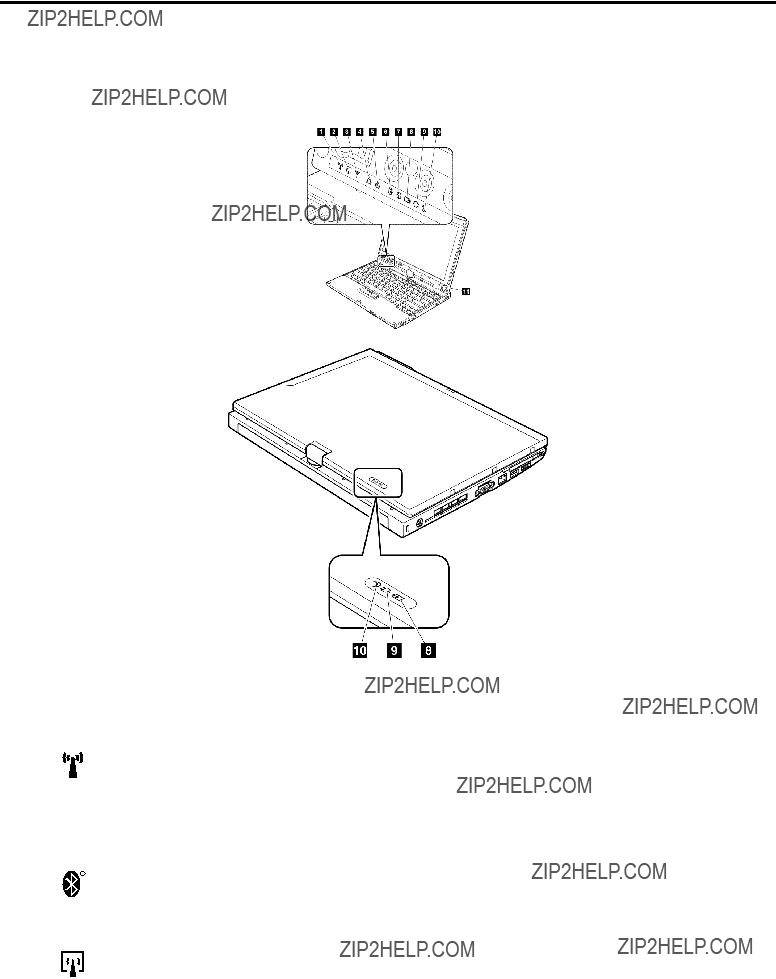
Chapter 5. Status indicators
This chapter presents the system status indicators that show the status of the computer.
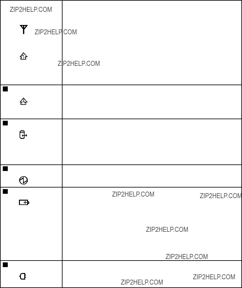
Table 7. Status indicators (continued)
5 Caps lock
Green: Caps Lock mode is enabled. To enable or disable Caps Lock mode, press the Caps Lock key.
6 Drive in use
Green: Data is being read from or written to the hard disk drive, the diskette drive, or the drive in the Serial Ultrabay Slim device. When this indicator is on, do not put the computer into sleep (standby) mode or turn off the computer.
Note: Do not move the system while the green
7 Power on
Green: The computer is on and ready to use. This indicator stays lit whenever the computer is on and is not in sleep (standby) mode.
8 Battery status
Green:The battery is charged between 80% to 100% of the capacity, and being discharged between 0% to 80% of the capacity.
Blinking green: The battery is charged between 20% to 80% of the capacity, and being charged.
Orange: The battery is charged between 5% and 20% of the capacity, and being discharged.
Blinking orange The battery is charged between 5% to 20% of the capacity, (slow):and being charged.
Blinking orange The battery is charged between 0% to 5% of the capacity.
(rapid):
9 AC power status
Green:The computer is connected to the ac power supply.
52 ThinkPad X200 Tablet and X201 Tablet Hardware Maintenance Manual
Table 7. Status indicators (continued)
10 Sleep (standby)
status
Green: The computer is in sleep (standby) mode.
Blinking The computer is entering sleep (standby) mode or hibernation mode, green: or is resuming normal operation.
Chapter 5. Status indicators 53
54 ThinkPad X200 Tablet and X201 Tablet Hardware Maintenance Manual
Chapter 6. Fn key combinations
The following table shows the function of each combination of Fn with a function key.
Table 8. Fn key combinations

Table 8. Fn key combinations (continued)
56 ThinkPad X200 Tablet and X201 Tablet Hardware Maintenance Manual
Chapter 7. FRU replacement notices
External CRU statement to customers:
Some problems with your product can be resolved with a replacement part you can install yourself, called a ???Customer Replaceable Unit??? or ???CRU.??? Some CRUs are designated as
Where you are installing the CRU, Lenovo will ship the CRU to you. CRU information and replacement instructions are shipped with your product and are available from Lenovo at any time upon request. You may find a list of CRUs in the publications that ship with your product or at http://www.lenovo.com/CRUs. You may be required to return the defective part that is replaced by the CRU. When return is required: (1) return instructions, a prepaid shipping label, and a container will be included with the replacement CRU; and (2) you may be charged for the replacement CRU if Lenovo does not receive the defective part within thirty (30) days of your receipt of the replacement CRU. See your Lenovo Limited Warranty documentation for full details.
This chapter presents notices related to removing and replacing parts. Read this chapter carefully before replacing any FRU.
Screw notices
Loose screws can cause a reliability problem. In the ThinkPad Notebook, this problem is addressed with special
???They maintain tight connections.
???They do not easily come loose, even with shock or vibration.
???They are harder to tighten.
???Each one should be used only once.
Do the following when you service this machine:
???Keep the screw kit (for the P/N, see ???Miscellaneous parts??? on page 178) in your tool bag.
???Always use new screws.
???Use a torque screwdriver if you have one.
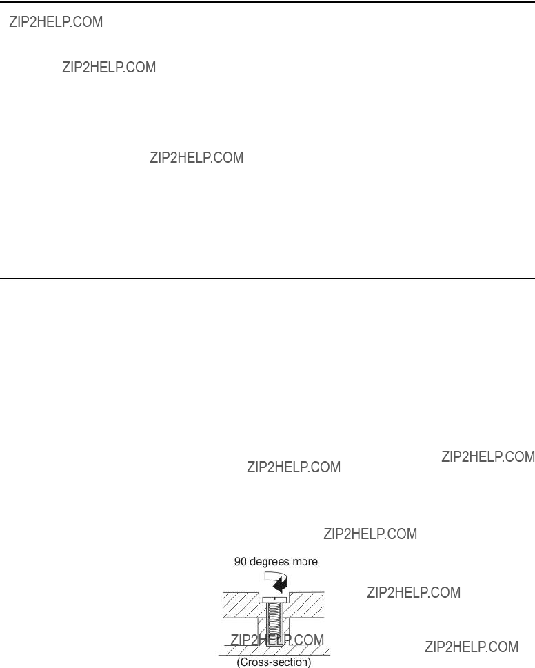
Tighten screws as follows:
???Plastic to plastic
Turn an additional 90 degrees after the screw head touches the surface of the plastic part:
???Logic card to plastic
Turn an additional 180 degrees after the screw head touches the surface of the logic card:

???Torque driver
If you have a torque driver, refer to the ???Torque??? column for each step.
???Make sure that you use the correct screw. If you have a torque screwdriver, tighten all screws firmly to the torque shown in the table. Never use a screw that you removed. Use a new one. Make sure that all of the screws are tightened firmly.
???Ensure torque screw drivers are calibrated correctly following country specifications.
Retaining serial numbers
This section includes the following descriptions:
??????Restoring the serial number of the system unit??? on page 58
??????Retaining the UUID??? on page 59
??????Reading or writing the ECA information??? on page 59
Restoring the serial number of the system unit
When the computer was manufactured, the EEPROM on the system board was loaded with the serial numbers of the system and all major components. These numbers need to remain the same throughout the life of the computer.
If you replace the system board, you must restore the serial number of the system unit to its original value.
Before replacing the system board, save the original serial number by doing the following:
1.Install the ThinkPad Hardware Maintenance Diskette Version 1.73 or later, and restart the computer.
2.From the main menu, select 1. Set System Identification.
3.Select 2. Read S/N data from EEPROM.
The serial number of each device in your computer is displayed; the serial number of the system unit is listed as follows:
??? 20: Serial number
Write down that number.
Note: The serial number of the system unit is also written on the label attached to the bottom of the computer.
After you have replaced the system board, restore the serial number by doing the following:
1.Install the ThinkPad Hardware Maintenance Diskette Version 1.73 or later and restart the computer.
2.From the main menu, select 1. Set System Identification.
3.Select 1. Add S/N data from EEPROM. Follow the instructions on the screen.
If the MTM and Product ID numbers differ from each other on the rear label, use what is shown for the Product ID field. See example below:
58 ThinkPad X200 Tablet and X201 Tablet Hardware Maintenance Manual
Product ID on rear label:
In the example, the Serial Number to be input is '1STTTTMMMSSSSSSS'.
Retaining the UUID
The Universally Unique Identifier (UUID) is a
When you replace the system board, you must set the UUID on the new system board as follows:
1.Install the ThinkPad Hardware Maintenance Diskette Version 1.73 or later, and restart the computer.
2.From the main menu, select 4. Assign UUID. A new UUID is created and written. If a valid UUID already exists, it is not overwritten.
Reading or writing the ECA information
Information on Engineering Change Announcements (ECA) are stored in the EEPROM of the system board. The electronic storage of this information simplifies the procedure to check if the ECA has been previously applied to a machine. The machine does not need to be disassembled to check for the ECA application.
To check what ECAs have been previously applied to the machine, use the ECA Information Read/Write function on the ThinkPad Hardware Maintenance Diskette Version 1.73 or later.
1.Insert the ThinkPad Hardware Maintenance Diskette Version 1.73 or later, and restart the computer.
2.From the main menu, select 6. Set ECA Information.
3.To read ECA information, select 2. Read ECA/rework number from EEPROM and follow the instruction.
4.To read box build date, select 5. Read box build date from EEPROM, and follow the instruction on the screen.
After an ECA has been applied to the machine, the EEPROM must be updated to reflect the ECA's application. Use the ThinkPad Hardware Maintenance Diskette Version 1.73 or later to update the EEPROM.
Note: Only the ECA number is stored in the EEPROM. The machine type of the ECA is assumed be the same as the machine type of the machine that had the ECA applied to it.
1.Insert the ThinkPad Hardware Maintenance Diskette Version 1.73 or later, and restart the computer.
2.From the main menu, select 6. Set ECA Information.
3.To write ECA information, select 1. Write ECA/rework number from EEPROM, and follow the instruction.
4.To write box build date, select 4. Write box build date from EEPROM, and follow the instruction on the screen.
If the system board is being replaced, try to read the ECA information from the old system board and transfer the information to the new system. If the system board is inoperable, this will not be possible.
Chapter 7. FRU replacement notices 59
60 ThinkPad X200 Tablet and X201 Tablet Hardware Maintenance Manual

Chapter 8. Removing and replacing a FRU
External CRU statement to customers:
Some problems with your product can be resolved with a replacement part you can install yourself, called a ???Customer Replaceable Unit??? or ???CRU.??? Some CRUs are designated as
Where you are installing the CRU, Lenovo will ship the CRU to you. CRU information and replacement instructions are shipped with your product and are available from Lenovo at any time upon request. You may find a list of CRUs in the publications that ship with your product or at http://www.lenovo.com/CRUs. You may be required to return the defective part that is replaced by the CRU. When return is required: (1) return instructions, a prepaid shipping label, and a container will be included with the replacement CRU; and (2) you may be charged for the replacement CRU if Lenovo does not receive the defective part within thirty (30) days of your receipt of the replacement CRU. See your Lenovo Limited Warranty documentation for full details.
This chapter presents directions and drawings for use in removing and replacing a FRU. Be sure to observe the following general rules:
1.Do not try to service any computer unless you have been trained and certified. An untrained person runs the risk of damaging parts.
2.Before replacing any FRU, review Chapter 7 ???FRU replacement notices??? on page 57.
3.Begin by removing any FRUs that have to be removed before the failing FRU. Any such FRUs are listed at the top of the page. Remove them in the order in which they are listed.
4.Follow the correct sequence in the steps for removing the FRU, as given in the drawings by the numbers in square callouts.
5.When turning a screw to replace a FRU, turn it in the direction as given by the arrow in the drawing.
6.When removing the FRU, move it in the direction as given by the arrow in the drawing.
7.To put the new FRU in place, reverse the removal procedure and follow any notes that pertain to replacement. For information about connecting and arranging internal cables, see Chapter 9 ???Locations??? on page 123.
8.When replacing a FRU, use the correct screw as shown in the procedures.
 DANGER
Before removing any FRU, turn off the computer, unplug all power cords from electrical outlets, remove the battery pack, and then disconnect any interconnecting cables.
Attention: After replacing a FRU, do not turn on the computer until you have made sure that all screws, springs, and other small parts are in place and none are loose inside the computer. Verify this by shaking the computer gently and listening for rattling sounds. Metallic parts or metal flakes can cause electrical short circuits.
Attention: The system board is sensitive to, and can be damaged by, electrostatic discharge. Before touching it, establish personal grounding by touching a ground point with one hand or by using an electrostatic discharge (ESD) strap (P/N 6405959).
Before servicing ThinkPad X200 Tablet and X201 Tablet
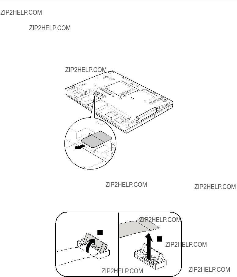
Removing the SIM card:
Some models of the ThinkPad X200 Tablet and X201 Tablet you are servicing might have the SIM card that the customer has been installed.
If the computer you are servicing has the SIM card, remove it before you start the servicing.
To remove the SIM card, you need to remove the battery pack first. (See ???1020 Battery pack??? on page 63.) After you finish the servicing, make sure that you insert the card back into the slot firmly.
Notice on disconnecting the cable from
Some cables used in the ThinkPad X200 Tablet and X201 Tablet are connected to the
1
2
62 ThinkPad X200 Tablet and X201 Tablet Hardware Maintenance Manual
1010 Digitizer pen
Table 9. Removal steps of digitizer pen
1020 Battery pack
Important notice for replacing a battery pack:
Lenovo ThinkVantage Toolbox (in Windows 7) and Lenovo System Toolbox (in Windows Vista and Windows XP) have an automatic battery diagnostic that determines if the battery pack is defective. A battery pack FRU should not be replaced unless this diagnostic shows that the battery is defective.
The only exception to this is if the battery pack is physically damaged or a customer is reporting a possible safety issue.
If ThinkVantage Toolbox or Lenovo System Toolbox is not installed in the computer, the customer should download this program before a
 DANGER
Use only the battery specified in the parts list for your computer. Any other battery could ignite or explode.
Chapter 8. Removing and replacing a FRU 63
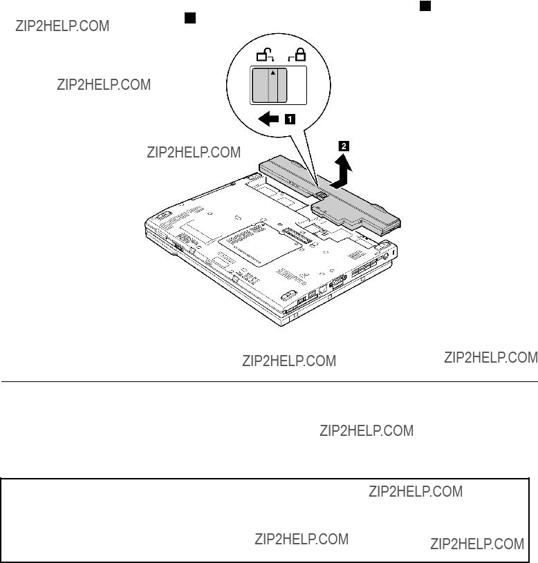
Table 10. Removal steps of battery pack
Unlock the battery release lever. Holding the battery release lever in the unlocked position 1 , remove the battery pack in the direction shown by arrow 2 .
When installing: Install the battery pack along the slide rails of the slot. Then make sure that the battery release lever is in the locked position.
1030 Hard disk drive (HDD) cover, HDD, and HDD rubber rails or solid state drive (SSD) and storage converter
For access, remove this FRU:
??????1020 Battery pack??? on page 63
Attention:
???Do not drop the hard disk drive or apply any physical shock to it. The hard disk drive is sensitive to physical shock. Improper handling can cause damage and permanent loss of data.
???Before removing the drive, have the user make a backup copy of all the information on it if possible.
???Never remove the drive while the system is operating or is in suspend mode.
64 ThinkPad X200 Tablet and X201 Tablet Hardware Maintenance Manual

Table 11. Removal steps of HDD cover, HDD, and HDD drive rubber rails or SSD and storage converter
Chapter 8. Removing and replacing a FRU 65
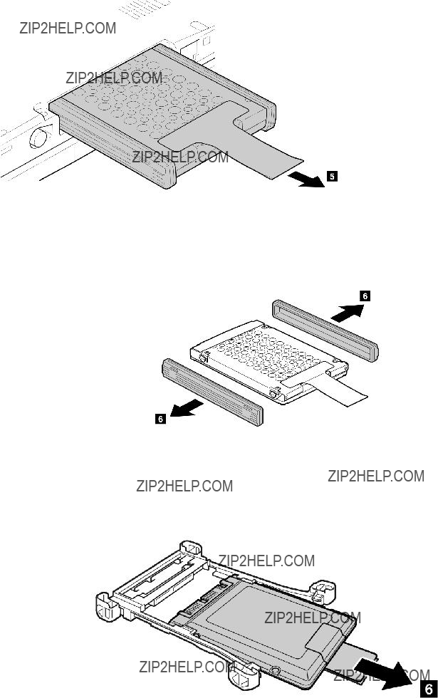
Table 11. Removal steps of HDD cover, HDD, and HDD drive rubber rails or SSD and storage converter (continued)
When installing: Make sure that the HDD connector or SSD connector is attached firmly.
HDD and HDD rubber rails:
When installing: The rubber rails on the hard disk drive must be attached to the replacement drive. Otherwise the drive cannot be installed properly.
SSD and storage converter:
66 ThinkPad X200 Tablet and X201 Tablet Hardware Maintenance Manual
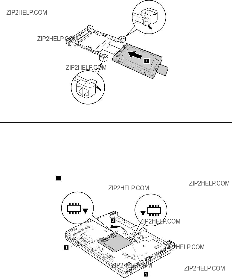
Table 11. Removal steps of HDD cover, HDD, and HDD drive rubber rails or SSD and storage converter (continued)
When installing: When you install the SSD in the storage converter, do as follows.
1040 DIMM
For access, remove this FRU in order:
??????1020 Battery pack??? on page 63
Table 12. Removal steps of dimm
Remove the DIMM slot cover as shown in this figure.
Note: Loosen the screws 1 , but do not remove them.
Chapter 8. Removing and replacing a FRU 67
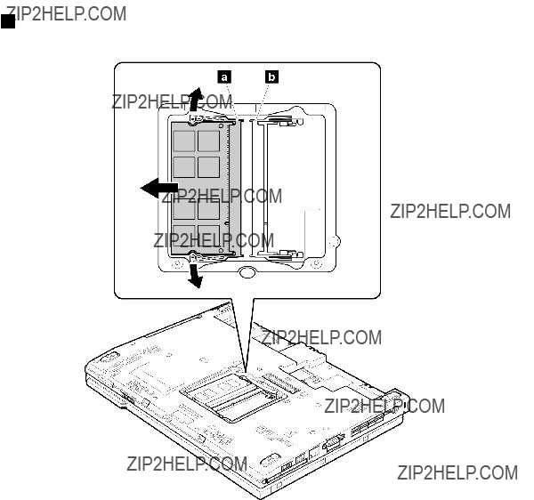
Table 12. Removal steps of dimm (continued)
For ThinkPad X200 Tablet:
Note: If only one DIMM is used on the computer you are servicing, the card must be installed in 
 ), but not in
For ThinkPad X201 Tablet:
68 ThinkPad X200 Tablet and X201 Tablet Hardware Maintenance Manual
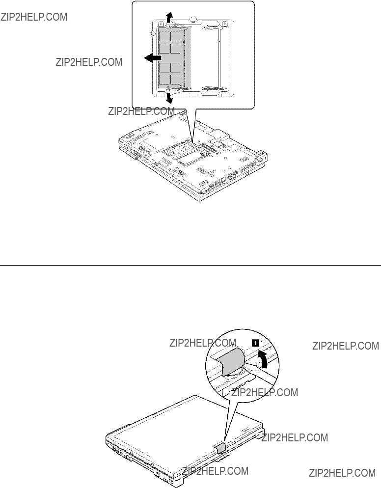
Table 12. Removal steps of dimm (continued)
When installing: Insert the notched end of the DIMM into the socket. Press the DIMM firmly, and pivot it until it snaps into the place. Make sure that it is firmly fixed in the slot and does not move easily.
1050 Hinge caps
For access, remove this FRU in order:
??????1020 Battery pack??? on page 63
Table 13. Removal steps of hinge caps
Chapter 8. Removing and replacing a FRU 69

Table 13. Removal steps of hinge caps (continued)
Open the LCD unit, and then remove the hinge cap (front).
Close the LCD unit, and then remove the hinge cap (rear).
1060 Keyboard
For access, remove this FRU in order:
70 ThinkPad X200 Tablet and X201 Tablet Hardware Maintenance Manual
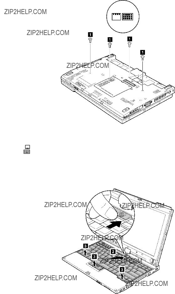
Table 14. Removal steps of keyboard
Chapter 8. Removing and replacing a FRU 71
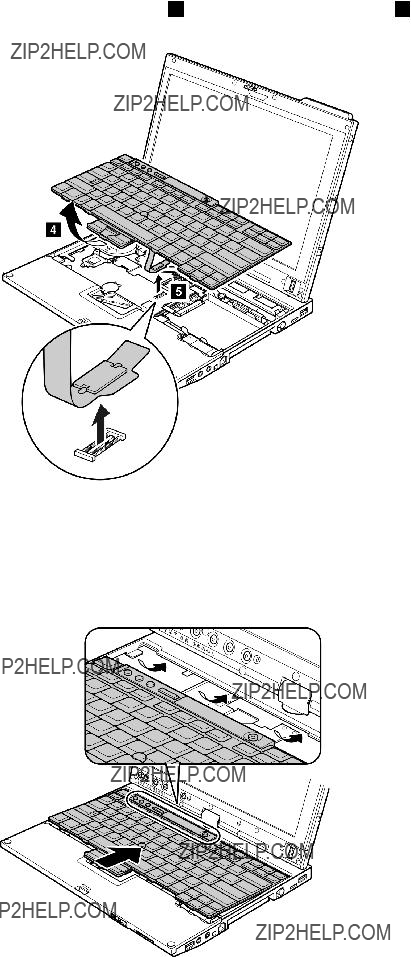
Table 14. Removal steps of keyboard (continued)
Lift the keyboard a little in the direction shown by arrow 4 , and then detach the connector 5 .
When installing:
1.Attach the keyboard connector firmly.
2.Make sure that the keyboard edges are under the frame as shown in this figure. Then press the keys to latch the keyboard firmly in place.
72 ThinkPad X200 Tablet and X201 Tablet Hardware Maintenance Manual
Table 14. Removal steps of keyboard (continued)
3. To make sure that the front side of the keyboard is housed firmly, gently press the keys with your thumbs and try to slide the keyboard toward you.
4. Secure the keyboard by tightening the screws from the bottom side of the computer.
1070 Extension cable card
For access, remove these FRUs in order:
Chapter 8. Removing and replacing a FRU 73
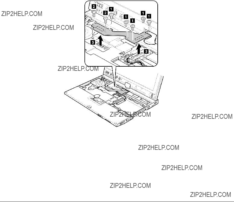
Table 15. Removal steps of Extension cable card
1080 Palm rest
For access, remove this FRU in order:
74 ThinkPad X200 Tablet and X201 Tablet Hardware Maintenance Manual

Table 16. Removal steps of palm rest
Chapter 8. Removing and replacing a FRU 75
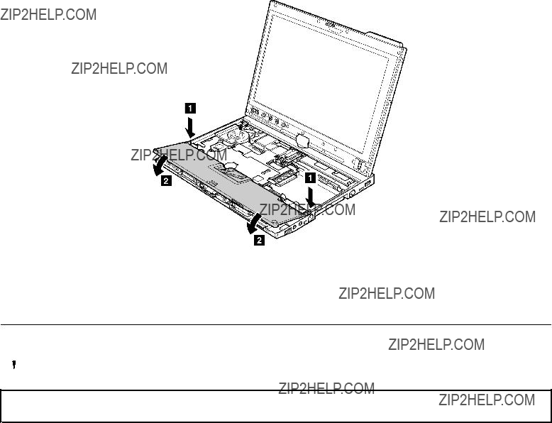
Table 16. Removal steps of palm rest (continued)
When installing: When you attach the palm rest, do as follows:
1.Attach the touch pad connector firmly to the system board.
2.Press the left and right top edges of the palm rest to fit it into place.
3.Push the front side of the palm rest until it clicks into place.
4. Close the LCD cover and turn the computer over. Then fasten the five screws to secure the palm rest.
1090 Backup battery
 DANGER
Use only the battery specified in the parts list for your computer. Any other battery could ignite or explode.
For access, remove these FRUs in order:
??????1020 Battery pack??? on page 63
76 ThinkPad X200 Tablet and X201 Tablet Hardware Maintenance Manual

Table 17. Removal steps of backup battery
When installing: Make sure that the battery connector is attached firmly.
1100 PCI Express Mini Card for wireless LAN/WiMAX
For access, remove these FRUs in order:
??????1020 Battery pack??? on page 63
Chapter 8. Removing and replacing a FRU 77
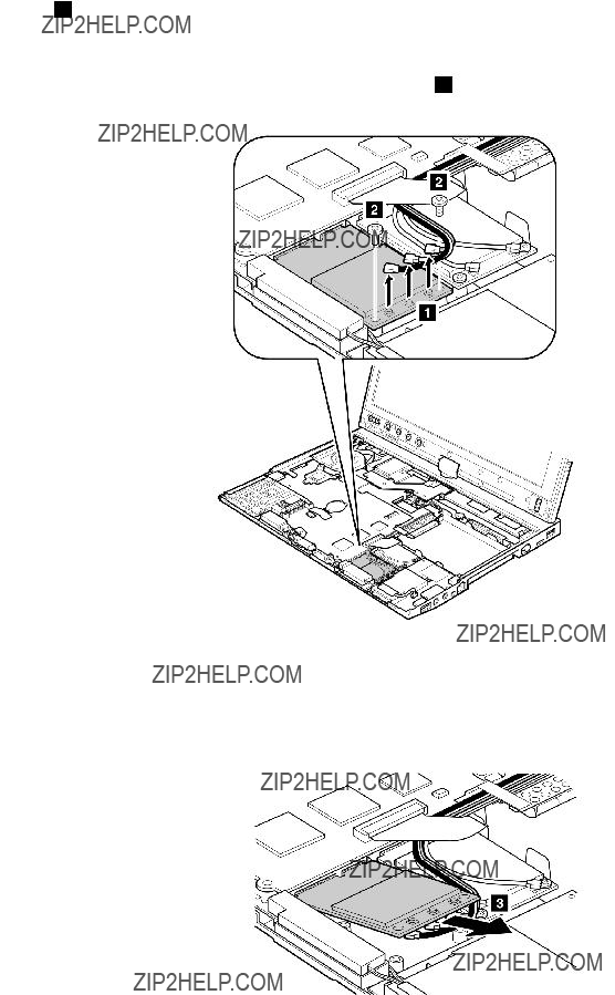
Table 18. Removal steps of PCI Express Mini Card for wireless LAN/WiMAX
Full size PCI express mini card:
In step 1 , unplug the jacks by using the removal tool antenna RF connector (P/N: 08K7159) or pick the connectors with your fingers and gently unplug them in direction of the arrow.
Note: Some models might have two antenna cables in step 1 .
78 ThinkPad X200 Tablet and X201 Tablet Hardware Maintenance Manual
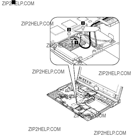
Table 18. Removal steps of PCI Express Mini Card for wireless LAN/WiMAX (continued)
When installing:
???In models with wireless LAN card that has two antenna connectors, plug the gray cable into the jack labeled MAIN or M on the card, and the black cable into the jack labeled AUX or A. If the computer you are servicing has three cables, put the white cable in the cable protection tube.
???In models with wireless LAN card that has three antenna connecotrs, plug the gray cable (MAIN) into the jack labeled TR1, the white cable (3rd) into jack labeled RO or TR3, and the black cable (AUX) into jack labeled TR2 on the card.
Harf size PCI express mini card:
In step 1 , unplug the jacks by using the removal tool antenna RF connector (P/N: 08K7159) or pick the connectors with your fingers and gently unplug them in direction of the arrow.
Chapter 8. Removing and replacing a FRU 79

Table 18. Removal steps of PCI Express Mini Card for wireless LAN/WiMAX (continued)
When installing: Plug the gray cable into the jack labeled MAIN on the card, and the black cable into the jack labeled AUX.
1110 PCI Express Mini Card for wireless WAN
For access, remove these FRUs in order:
??????1020 Battery pack??? on page 63
??????1060 Keyboard??? on page 70
??????1080 Palm rest??? on page 74
Table 19. Removal steps of PCI Express Mini Card for wireless WAN
In step 1 , unplug the jacks by using the removal tool antenna RF connector (P/N: 08K7159) or pick the connectors with your fingers and gently unplug them in direction of the arrow.
80 ThinkPad X200 Tablet and X201 Tablet Hardware Maintenance Manual
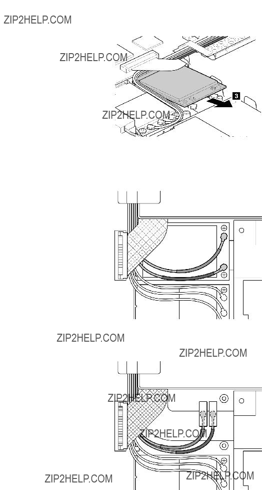
Table 19. Removal steps of PCI Express Mini Card for wireless WAN (continued)
When installing: When you install the card, plug the red cable into the jack labeled MAIN on the card, and the blue cable into the jack labeled AUX.
If the computer you are servicing is the wireless
Chapter 8. Removing and replacing a FRU 81

Table 19. Removal steps of PCI Express Mini Card for wireless WAN (continued)
1120 Intel Turbo Memory Minicard or Wireless USB PCI Express
For access, remove these FRUs in order:
??????1020 Battery pack??? on page 63
??????1060 Keyboard??? on page 70
??????1080 Palm rest??? on page 74
Table 20. Removal steps of Intel Turbo Memory Minicard or Wireless USB PCI Express
Note: Step 1 is only for models with the Wireless USB PCI Express
In step 1 , unplug the jacks by using the removal tool antenna RF connector (P/N: 08K7159) or pick the connectors with your fingers and gently unplug them in direction of the arrow.
82 ThinkPad X200 Tablet and X201 Tablet Hardware Maintenance Manual
Table 20. Removal steps of Intel Turbo Memory Minicard or Wireless USB PCI Express
When installing: In models with the Wireless USB PCI Express
1130 Bluetooth daughter card
For access, remove these FRUs in order:
??????1020 Battery pack??? on page 63
??????1060 Keyboard??? on page 70
??????1080 Palm rest??? on page 74
Table 21. Removal steps of Bluetooth daughter card
Chapter 8. Removing and replacing a FRU 83

Table 21. Removal steps of Bluetooth daughter card (continued)
When installing: Make sure that the connector 2 is attached firmly.
Turn the Bluetooth daughter card over, and then disconnect the cable from the connector.
When installing: Make sure that the connector 4 is attached firmly.
1140 Keyboard bezel
For access, remove these FRUs in order:
??????1010 Digitizer pen??? on page 63
??????1020 Battery pack??? on page 63
??????1060 Keyboard??? on page 70
??????1080 Palm rest??? on page 74
Table 22. Removal steps of keyboard bezel
84 ThinkPad X200 Tablet and X201 Tablet Hardware Maintenance Manual
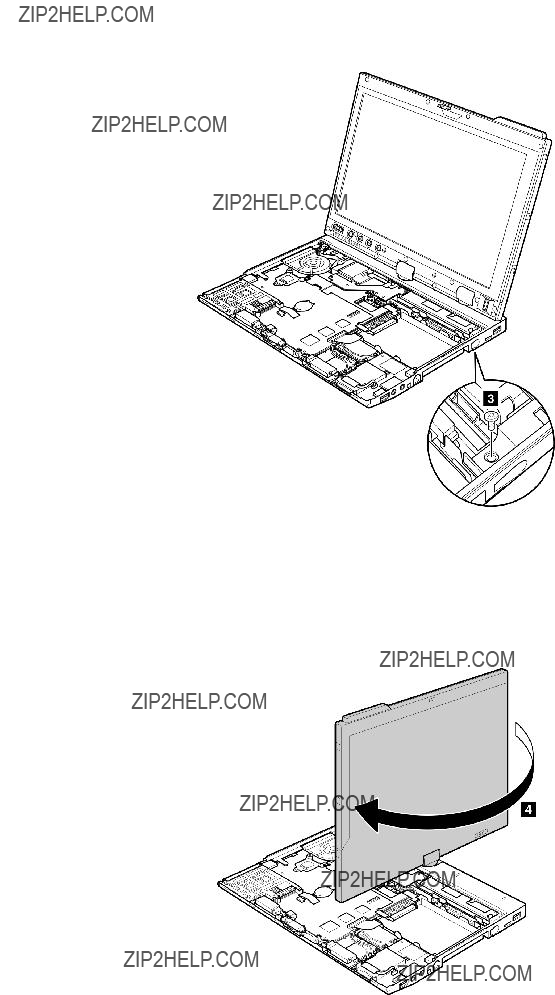
Table 22. Removal steps of keyboard bezel (continued)
Rotate the LCD unit as shown in this figure.
Chapter 8. Removing and replacing a FRU 85
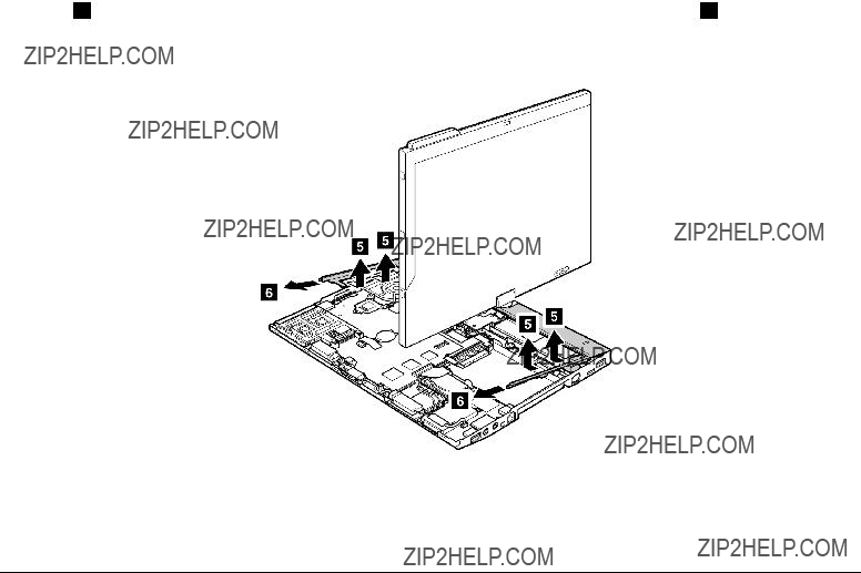
Table 22. Removal steps of keyboard bezel (continued)
In step 5 , detach the claws. Then remove the keyboard bezel in the direction shown by arrow 6 .
Attention: When you service the keyboard bezel, avoid any kind of rough handling.
When installing: Make sure that all the claws are attached firmly.
1150 I/O card assembly
For access, remove these FRUs in order:
??????1010 Digitizer pen??? on page 63
??????1020 Battery pack??? on page 63
??????1060 Keyboard??? on page 70
??????1080 Palm rest??? on page 74
??????1110 PCI Express Mini Card for wireless WAN??? on page 80
86 ThinkPad X200 Tablet and X201 Tablet Hardware Maintenance Manual
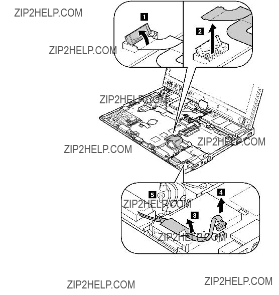
Table 23. Removal steps of I/O card assembly
Chapter 8. Removing and replacing a FRU 87

Table 23. Removal steps of I/O card assembly (continued)
Turn the I/O card over, and then disconnect the cable from the
1160 USB sub card
For access, remove these FRUs in order:
??????1010 Digitizer pen??? on page 63
??????1020 Battery pack??? on page 63
??????1060 Keyboard??? on page 70
88 ThinkPad X200 Tablet and X201 Tablet Hardware Maintenance Manual

Table 24. Removal steps of USB sub card
Turn the USB sub card over, an then disconnect the cable from the connector.
Chapter 8. Removing and replacing a FRU 89

Table 24. Removal steps of USB sub card (continued)
When installing: Route the cable as shown in this figure.
1170 LCD assembly
For access, remove these FRUs in order:
??????1010 Digitizer pen??? on page 63
??????1020 Battery pack??? on page 63
??????1050 Hinge caps??? on page 69
??????1060 Keyboard??? on page 70
??????1070 Extension cable card??? on page 73
??????1080 Palm rest??? on page 74
??????1100 PCI Express Mini Card for wireless LAN/WiMAX??? on page 77
??????1110 PCI Express Mini Card for wireless WAN??? on page 80
??????1120 Intel Turbo Memory Minicard or Wireless USB PCI Express
??????1140 Keyboard bezel??? on page 84
Table 25. Removal steps of LCD assembly
90 ThinkPad X200 Tablet and X201 Tablet Hardware Maintenance Manual

Table 25. Removal steps of LCD assembly (continued)
Before step 3 , strip off the tapes securing the antenna cables, and release the cables from the cable guides of the frame.
Chapter 8. Removing and replacing a FRU 91
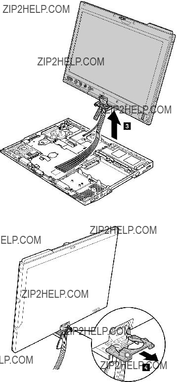
Table 25. Removal steps of LCD assembly (continued)
92 ThinkPad X200 Tablet and X201 Tablet Hardware Maintenance Manual
Table 25. Removal steps of LCD assembly (continued)
When installing: Route the antenna cables along the cable guides and secure them with the tapes. As you route the cables, make sure that they are not subjected to any tension. Tension could cause the cables to be damaged by the cable guides, or a wire to be broken.
1180
For access, remove these FRUs in order:
??????1010 Digitizer pen??? on page 63
??????1020 Battery pack??? on page 63
??????1050 Hinge caps??? on page 69
??????1060 Keyboard??? on page 70
??????1070 Extension cable card??? on page 73
??????1080 Palm rest??? on page 74
??????1100 PCI Express Mini Card for wireless LAN/WiMAX??? on page 77
??????1110 PCI Express Mini Card for wireless WAN??? on page 80
??????1120 Intel Turbo Memory Minicard or Wireless USB PCI Express
??????1130 Bluetooth daughter card
??????1140 Keyboard bezel??? on page 84
??????1150 I/O card assembly??? on page 86
??????1160 USB sub card??? on page 88
??????1170 LCD assembly??? on page 90
Table 26. Removal steps of
Remove the top shielding assembly at first.
Chapter 8. Removing and replacing a FRU 93

Table 26. Removal steps of
94 ThinkPad X200 Tablet and X201 Tablet Hardware Maintenance Manual

Table 26. Removal steps of
Chapter 8. Removing and replacing a FRU 95

Table 26. Removal steps of
When installing: Attach the wireless radio switch as shown in the figure 
 .
.
96 ThinkPad X200 Tablet and X201 Tablet Hardware Maintenance Manual

Table 26. Removal steps of
Turn the system board over, and then disconnect the
When installing: Make sure that the
Chapter 8. Removing and replacing a FRU 97
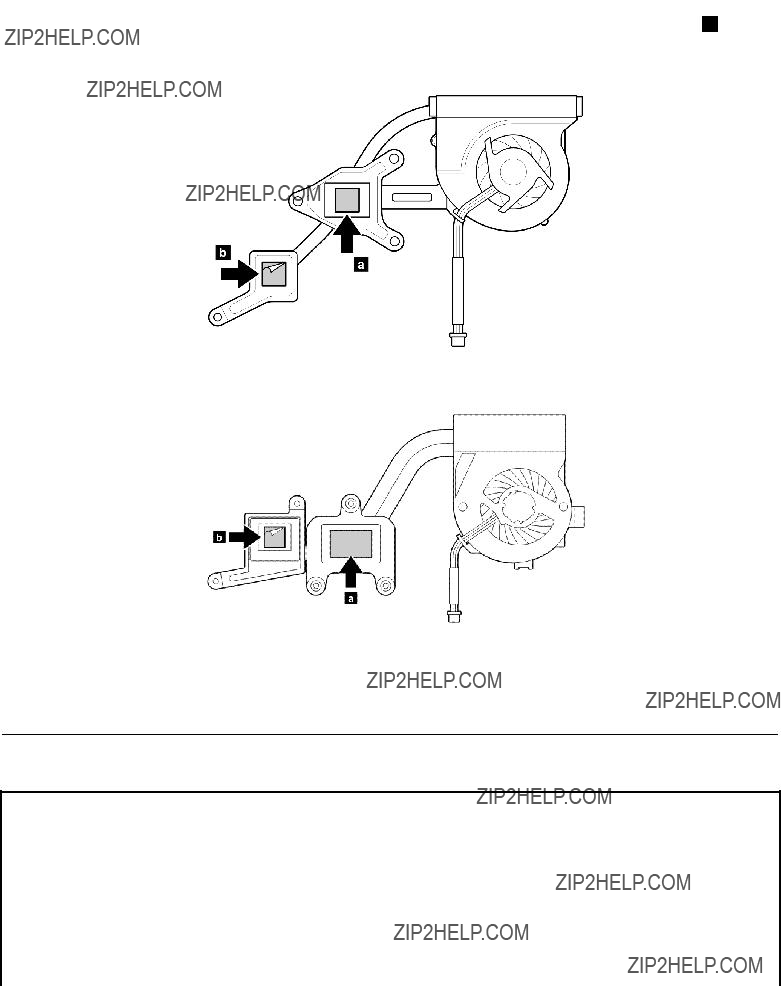
Table 26. Removal steps of
When installing:
???Before you attach the fan assembly to the computer, apply thermal grease, at an amount of 0.2 grams, on the
part marked 

 as in the following figure. Either too much or too less application of grease can cause a thermal problem due to imperfect contact with a component. You need to peel the thin film off from the rubber b .
For ThinkPad X200 Tablet:
For ThinkPad X201 Tablet:
??? Make sure that the fan connector is attached firmly.
1190 System board and ExpressCard slot assemblys
Important notices for handling the system board:
When handling the system board, bear the following in mind.
???The system board has an accelerometer, which can be broken by applying several thousands of
Note: Dropping a system board from a height of as little as 6 inches so that it falls flat on a hard bench can subject the accelerometer to as much as 6,000 G's of shock.
???Be careful not to drop the system board on a bench top that has a hard surface, such as metal, wood, or composite.
???If a system board is dropped, you must test it, using
98 ThinkPad X200 Tablet and X201 Tablet Hardware Maintenance Manual
Active Protection still functions (see below).
Note: If the test shows that HDD Active Protection is not functioning, be sure to document the drop in any reject report, and replace the system board.
???Avoid rough handling of any kind.
???At every point in the process, be sure not to drop or stack the system board.
???If you put a system board down, be sure to put it only on a padded surface such as an ESD mat or conductive corrugated material.
After replacing the system board, run
1.Place the computer on a horizontal surface.
2.Run Diagnostics>ThinkPad Devices>HDD Active Protection Test.
Attention: Do not apply physical shock to the computer while the test is running.
For access, remove these FRUs in order:
??????1010 Digitizer pen??? on page 63
??????1020 Battery pack??? on page 63
??????1050 Hinge caps??? on page 69
??????1060 Keyboard??? on page 70
??????1070 Extension cable card??? on page 73
??????1080 Palm rest??? on page 74
??????1100 PCI Express Mini Card for wireless LAN/WiMAX??? on page 77
??????1110 PCI Express Mini Card for wireless WAN??? on page 80
??????1120 Intel Turbo Memory Minicard or Wireless USB PCI Express
??????1130 Bluetooth daughter card
??????1140 Keyboard bezel??? on page 84
??????1150 I/O card assembly??? on page 86
??????1160 USB sub card??? on page 88
??????1170 LCD assembly??? on page 90
??????1180
Table 27. Removal steps of system board and ExpressCard slot assembly
Following components soldered on the system board are extremely sensitive. When you service the system board, avoid any kind of rough handling.
For ThinkPad X200 Tablet:
Top
Chapter 8. Removing and replacing a FRU 99

Table 27. Removal steps of system board and ExpressCard slot assembly (continued)
Bottom
For ThinkPad X201 Tablet:
CPU
bPCH (Platform Controller Hub)
Accelerometer chip for the HDD Active Protection System
Bottom
100 ThinkPad X200 Tablet and X201 Tablet Hardware Maintenance Manual
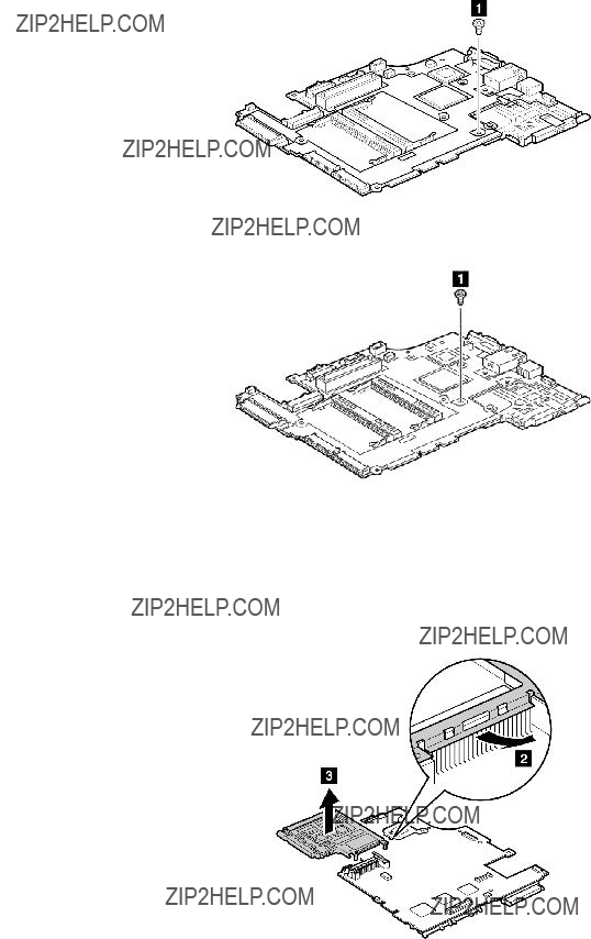
Table 27. Removal steps of system board and ExpressCard slot assembly (continued)
Note: The ExpressCard slot assembly is attached to the system board.
For ThinkPad X200 Tablet:
For ThinkPad X201 Tablet:
Turn the system board over, and then remove the ExpressCard slot assembly from the system board.
Chapter 8. Removing and replacing a FRU 101

1200 Base cover and speaker assembly
For access, remove these FRUs in order:
??????1010 Digitizer pen??? on page 63
??????1020 Battery pack??? on page 63
??????1050 Hinge caps??? on page 69
??????1060 Keyboard??? on page 70
??????1070 Extension cable card??? on page 73
??????1080 Palm rest??? on page 74
??????1100 PCI Express Mini Card for wireless LAN/WiMAX??? on page 77
??????1110 PCI Express Mini Card for wireless WAN??? on page 80
??????1120 Intel Turbo Memory Minicard or Wireless USB PCI Express
??????1130 Bluetooth daughter card
??????1140 Keyboard bezel??? on page 84
??????1150 I/O card assembly??? on page 86
??????1160 USB sub card??? on page 88
??????1170 LCD assembly??? on page 90
??????1180
Table 28. Removal steps of base cover and speaker assembly
Remove the speaker assembly from the base cover assembly.
When installing: Route the speaker cables along the cable guides as shown in this figure.
102 ThinkPad X200 Tablet and X201 Tablet Hardware Maintenance Manual
Applying labels to the base cover:
The new base cover FRU is shipped with a kit containing labels of several kinds. When you replace the base cover, you need to apply the following labels:
Following labels need to be peeled off from the old base cover, and need to be put on the new base cover.
For some models, you need to apply two or three FCC labels, 7 or 8 and 10 . Check the old base cover; if it has two or three FCC labels, find duplicates of them in the label kit and apply them to the new base cover.
For the location of each label, refer the following figure:
Chapter 8. Removing and replacing a FRU 103

For some models, you need to apply one or two FCC labels, 7a and 10 . Check the old base cover; if it has one or two FCC labels, find duplicates of them in the label kit and apply them to the new base cover.
For the location of each label, refer the following figure:
2010 LCD front bezel
For access, remove this FRU:
???For access, remove this FRU:
??? ???1020 Battery pack??? on page 63
Table 29. Removal steps of LCD front bezel for protection plate LCD model
Protection plate LCD model:
104 ThinkPad X200 Tablet and X201 Tablet Hardware Maintenance Manual
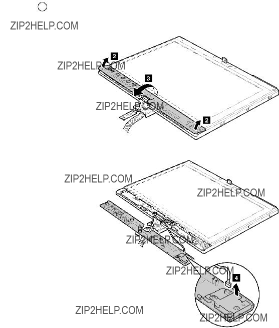
Table 29. Removal steps of LCD front bezel for protection plate LCD model (continued)
When installing: Attach the fingerprint reader connector firmly.
Table 30. Removal steps of LCD front bezel for touch panel LCD model or
Touch panel LCD model or direct bonding glass LCD model:
Chapter 8. Removing and replacing a FRU 105
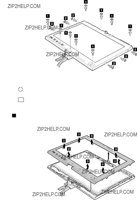
Table 30. Removal steps of LCD front bezel for touch panel LCD model or
When installing: Make sure that all the claws are attached firmly.
106 ThinkPad X200 Tablet and X201 Tablet Hardware Maintenance Manual
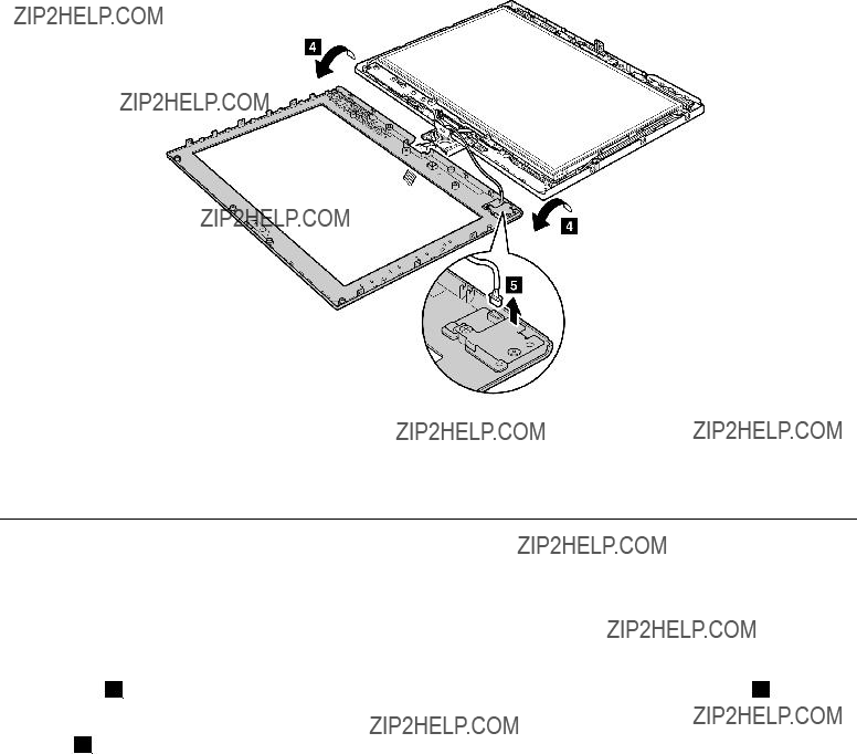
Table 30. Removal steps of LCD front bezel for touch panel LCD model or
When installing: Make sure that attach the fingerprint reader connector firmly.
2020
For access, remove these FRUs in order:
??????1020 Battery pack??? on page 63
??????2010 LCD front bezel??? on page 104
Table 31. Removal steps of
Note: Step 1 is only for models with the inverter card. For models without the inverter card, skip step 1 .
In step 1 , detach the connector from the inverter card.
Chapter 8. Removing and replacing a FRU 107
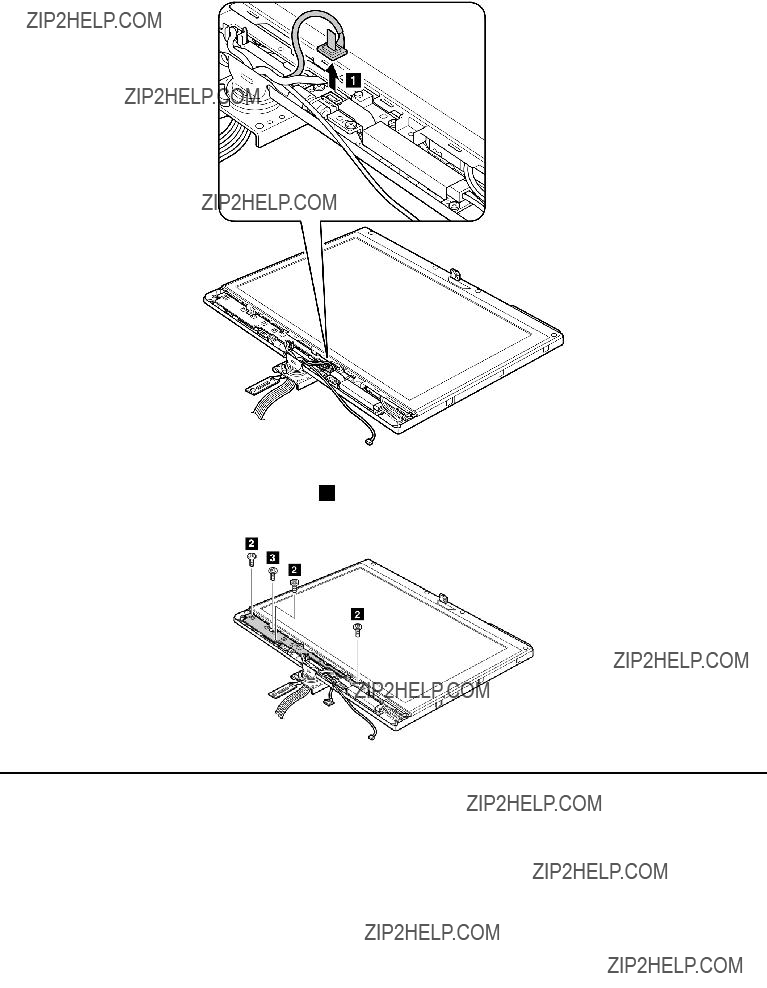
Table 31. Removal steps of
When installing: Make sure that the connector 1 is attached firmly.
Protection plate LCD model
108 ThinkPad X200 Tablet and X201 Tablet Hardware Maintenance Manual

Table 31. Removal steps of
When installing: Make sure that the connector 5 is attached firmly.
2030 Inverter card
For access, remove these FRUs in order:
??????1020 Battery pack??? on page 63
??????2010 LCD front bezel??? on page 104
??????2020
Table 32. Removal steps of inverter card
Note: Some models do no have the inverter card.
Chapter 8. Removing and replacing a FRU 109
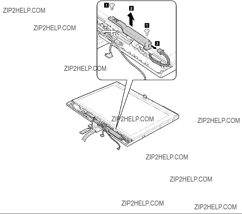
Table 32. Removal steps of inverter card (continued)
2040 Hinges
For access, remove these FRUs in order:
??????1010 Digitizer pen??? on page 63
??????1020 Battery pack??? on page 63
??????1050 Hinge caps??? on page 69
??????1060 Keyboard??? on page 70
??????1070 Extension cable card??? on page 73
??????1080 Palm rest??? on page 74
??????1100 PCI Express Mini Card for wireless LAN/WiMAX??? on page 77
??????1110 PCI Express Mini Card for wireless WAN??? on page 80
??????1120 Intel Turbo Memory Minicard or Wireless USB PCI Express
??????1140 Keyboard bezel??? on page 84
??????1170 LCD assembly??? on page 90
??????2010 LCD front bezel??? on page 104
110 ThinkPad X200 Tablet and X201 Tablet Hardware Maintenance Manual
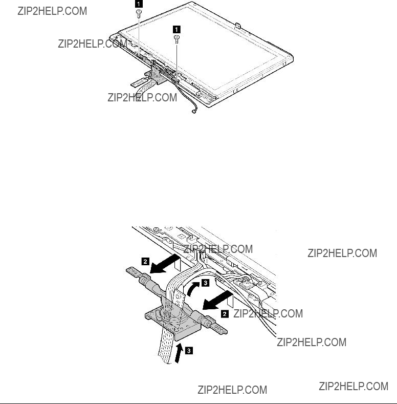
Table 33. Removal steps of hinge
Detach the hinge from the LCD rear cover, and gently pull the cables out through the guide hole in the hinge. Pull them all at once. As you pull them, be sure not to subject them to any tension, which could cause them to be damaged by the cable guides, or could break a wire.
2050 LCD panel, LCD bracket L and R, and LCD cable
For access, remove these FRUs in order:
??????1010 Digitizer pen??? on page 63
??????1020 Battery pack??? on page 63
??????1050 Hinge caps??? on page 69
??????1060 Keyboard??? on page 70
??????1070 Extension cable card??? on page 73
??????1080 Palm rest??? on page 74
??????1100 PCI Express Mini Card for wireless LAN/WiMAX??? on page 77
??????1110 PCI Express Mini Card for wireless WAN??? on page 80
??????1120 Intel Turbo Memory Minicard or Wireless USB PCI Express
Chapter 8. Removing and replacing a FRU 111

??????1140 Keyboard bezel??? on page 84
??????1170 LCD assembly??? on page 90
??????2010 LCD front bezel??? on page 104
??????2020
??????2030 Inverter card??? on page 109
??????2040 Hinges??? on page 110
Table 34. Removal steps of LCD panel and LCD cable for protection plate LCD model
Protection plate LCD model:
112 ThinkPad X200 Tablet and X201 Tablet Hardware Maintenance Manual
Table 34. Removal steps of LCD panel and LCD cable for protection plate LCD model (continued)
When installing: Make sure that all the claws are attached firmly.
Note: Step 5 is only for models with the integrated camera. For models without the integrated camera, skip step 5 .
Chapter 8. Removing and replacing a FRU 113
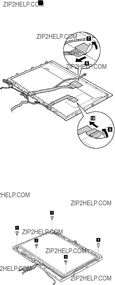
Table 34. Removal steps of LCD panel and LCD cable for protection plate LCD model (continued)
When installing: Make sure that the connector 5 is attached firmly.
Turn the LCD panel over, and then remove the LCD cable from the LCD panel.
When installing: Make sure that the LCD cable connector are attached firmly.
Table 35. Removal steps of LCD panel, LCD bracket L and R, and LCD cable for touch panel LCD model or
Touch panel LCD model or direct bonding glass LCD model:
114 ThinkPad X200 Tablet and X201 Tablet Hardware Maintenance Manual

Table 35. Removal steps of LCD panel, LCD bracket L and R, and LCD cable for touch panel LCD model or
When installing: Make sure that the connector 2 is attached firmly.
Chapter 8. Removing and replacing a FRU 115
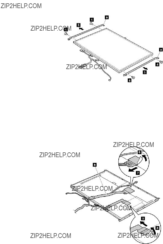
Table 35. Removal steps of LCD panel, LCD bracket L and R, and LCD cable for touch panel LCD model or
Remove the LCD bracket L and R 
 .
.
Single touch panel LCD model or direct bonding glass LCD model:
When installing: Make sure that the LCD cable connector are attached firmly.
116 ThinkPad X200 Tablet and X201 Tablet Hardware Maintenance Manual

Table 35. Removal steps of LCD panel, LCD bracket L and R, and LCD cable for touch panel LCD model or
Multitouch panel LCD model:
When installing: Make sure that the LCD cable connector are attached firmly.
2060 Integrated camera
For access, remove these FRUs in order:
??????1010 Digitizer pen??? on page 63
??????1020 Battery pack??? on page 63
??????1050 Hinge caps??? on page 69
??????1060 Keyboard??? on page 70
??????1070 Extension cable card??? on page 73
??????1080 Palm rest??? on page 74
??????1100 PCI Express Mini Card for wireless LAN/WiMAX??? on page 77
??????1110 PCI Express Mini Card for wireless WAN??? on page 80
??????1120 Intel Turbo Memory Minicard or Wireless USB PCI Express
??????1140 Keyboard bezel??? on page 84
??????1170 LCD assembly??? on page 90
??????2010 LCD front bezel??? on page 104
??????2020
??????2030 Inverter card??? on page 109
??????2040 Hinges??? on page 110
??????2050 LCD panel, LCD bracket L and R, and LCD cable??? on page 111
Chapter 8. Removing and replacing a FRU 117

Table 36. Removal steps of Integrated camera
2070 LCD rear cover and wireless antenna cables
For access, remove these FRUs in order:
??????1010 Digitizer pen??? on page 63
??????1020 Battery pack??? on page 63
??????1050 Hinge caps??? on page 69
??????1060 Keyboard??? on page 70
??????1070 Extension cable card??? on page 73
??????1080 Palm rest??? on page 74
??????1100 PCI Express Mini Card for wireless LAN/WiMAX??? on page 77
??????1110 PCI Express Mini Card for wireless WAN??? on page 80
??????1120 Intel Turbo Memory Minicard or Wireless USB PCI Express
??????1140 Keyboard bezel??? on page 84
??????1170 LCD assembly??? on page 90
??????2010 LCD front bezel??? on page 104
??????2020
??????2030 Inverter card??? on page 109
??????2040 Hinges??? on page 110
??????2050 LCD panel, LCD bracket L and R, and LCD cable??? on page 111
118 ThinkPad X200 Tablet and X201 Tablet Hardware Maintenance Manual
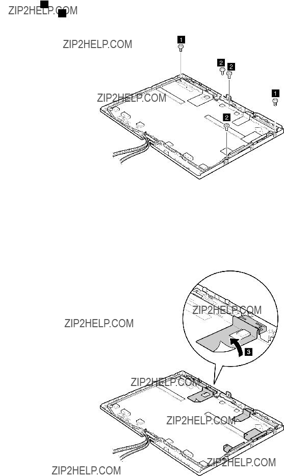
Table 37. Removal steps of LCD rear cover and wireless antenna cables
Note: Step 1 is only for protection plate LCD model. For touch panel LCD model or
Chapter 8. Removing and replacing a FRU 119
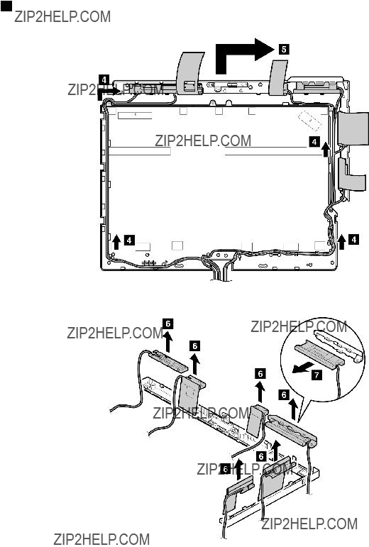
Table 37. Removal steps of LCD rear cover and wireless antenna cables (continued)
In step 4 , release the antenna cables from the cable guides of the rear cover.
Remove the center latch from the LCD rear cover.
120 ThinkPad X200 Tablet and X201 Tablet Hardware Maintenance Manual

Table 37. Removal steps of LCD rear cover and wireless antenna cables (continued)
b
d
f
Wireless WAN antenna, AUX (blue) Wireless LAN antenna, AUX (black) Wireless USB antenna (yellow)
Wireless WAN antenna, MAIN (red) Wireless LAN antenna, MAIN (gray) MIMO antenna (white)
Chapter 8. Removing and replacing a FRU 121
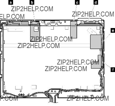
Table 37. Removal steps of LCD rear cover and wireless antenna cables (continued)
Attention: As you route the antenna cables, make sure that they are not subjected to any tension. Tension could cause the cables to be damaged by the cable guides, or a wire to be broken.
122 ThinkPad X200 Tablet and X201 Tablet Hardware Maintenance Manual
Chapter 9. Locations
This chapter presents the location of ThinkPad X200 Tablet and X201 Tablet features and hardware.
Front view
1Center latch
2Integrated camera (for some models)
3Universal serial bus (USB) connector
4Tablet digitizer pen
5Hard disk drive (HDD) or solid state drive (SSD)
6
7Microphone jack
8Stereo headphone jack
9Universal serial bus (USB) connector
10TrackPoint pointing stick
11TrackPoint buttons
12Touch pad buttons
13Touch pad
14UltraNav??
15Volume control buttons
16ThinkVantage button
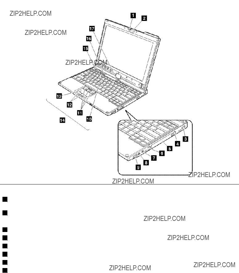
Rear view
1Status indicators
Note: For the description of each indicator, see Chapter 5 ???Status indicators??? on page 51.
2ExpressCard slot
3Wireless radio switch
4Universal Serial Bus (USB) connector
5
6External monitor connector
7AC power connector
8Security key hole
124 ThinkPad X200 Tablet and X201 Tablet Hardware Maintenance Manual

Rear view (tablet mode)
1Tablet buttons
2Fingerprint reader
3Status indicators
Note: For the description of each indicator, see Chapter 5 ???Status indicators??? on page 51.
Chapter 9. Locations 125
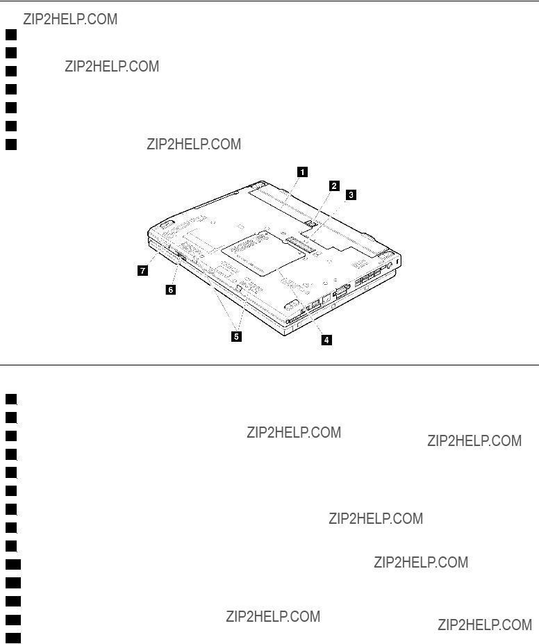
Bottom view
1Battery pack
2Battery pack latch
3Docking connector
4DIMM slots
5LCD cover latch
6
7
Rear view (ThinkPad X200 UltraBase)
1AC power connector
2Universal serial bus (USB) connectors
3External monitor connector
4DisplayPort connector
5Headphone jack
6Microphone jack
7
8Security keyhole
9Security lock key
10Universal serial bus (USB) connector
11Serial Ultrabay Slim device release latch
12Serial Ultrabay Slim device eject lever
13Serial Ultrabay Slim device
14Docking connector
126 ThinkPad X200 Tablet and X201 Tablet Hardware Maintenance Manual

Bottom view (ThinkPad X200 UltraBase)
1Battery charger (behind the
2UltraBase eject request button
3UltraBase eject lever
4Power button security latch
5Power button
6
Chapter 9. Locations 127
128 ThinkPad X200 Tablet and X201 Tablet Hardware Maintenance Manual

Chapter 10. Parts list
This section contains following lists of the service parts.
??????LCD FRUs for touch panel LCD or
??????LCD FRUs for protection plate LCD??? on page 169
??????Miscellaneous parts??? on page 178
??????AC adapters??? on page 180
??????Power cords??? on page 180
??????Recovery discs??? on page 181
??????Common service tools??? on page 193
Notes:
???Each FRU is available for all types or models, unless specific types or models are specified.
???FRU with specific models listed and described as xxU (where U is an example of a country designator) should be used for all models ending in U.
???FRU with specific models listed and described as 3Dx (where 3D is an example of a unique configuration) should be used for all of these models, unless specific country or region designator is specified.
???A CRU (customer replaceable unit) is identified by a single asterisk (*) or two asterisks (**) in the CRU ID column. An N in the CRU ID column means that the part is not a CRU. A single asterisk (*) means that the part is a
External CRU statement to customers:
Some problems with your product can be resolved with a replacement part you can install yourself, called a ???Customer Replaceable Unit??? or ???CRU.??? Some CRUs are designated as
Where you are installing the CRU, Lenovo will ship the CRU to you. CRU information and replacement instructions are shipped with your product and are available from Lenovo at any time upon request. You may find a list of CRUs in the publications that ship with your product or at http://www.lenovo.com/CRUs. You may be required to return the defective part that is replaced by the CRU. When return is required:
(1) return instructions, a prepaid shipping label, and a container will be included with the replacement CRU; and (2) you may be charged for the replacement CRU if Lenovo does not receive the defective part within thirty (30) days of your receipt of the replacement CRU. See your Lenovo Limited Warranty documentation for full details.
ThinkPad computers contain the following types of CRUs:
???
???
???FRUs marked with OP are available as options.
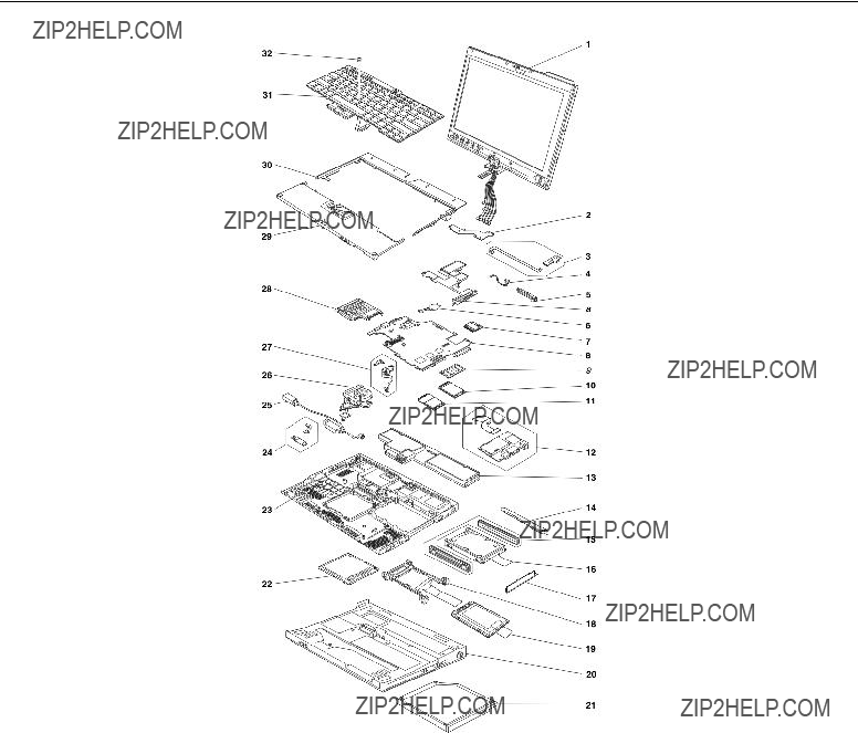
Overall
Table 38. Parts list - Overall
130 ThinkPad X200 Tablet and X201 Tablet Hardware Maintenance Manual
Table 38. Parts list - Overall (continued)
Chapter 10. Parts list 131
Table 38. Parts list - Overall (continued)
132 ThinkPad X200 Tablet and X201 Tablet Hardware Maintenance Manual
Table 38. Parts list - Overall (continued)
Chapter 10. Parts list 133
Table 38. Parts list - Overall (continued)
134 ThinkPad X200 Tablet and X201 Tablet Hardware Maintenance Manual
Table 38. Parts list - Overall (continued)
Chapter 10. Parts list 135
Table 38. Parts list - Overall (continued)
136 ThinkPad X200 Tablet and X201 Tablet Hardware Maintenance Manual
Table 38. Parts list - Overall (continued)
Chapter 10. Parts list 137
Table 38. Parts list - Overall (continued)
138 ThinkPad X200 Tablet and X201 Tablet Hardware Maintenance Manual
Table 38. Parts list - Overall (continued)
Chapter 10. Parts list 139
Table 38. Parts list - Overall (continued)
140 ThinkPad X200 Tablet and X201 Tablet Hardware Maintenance Manual
Table 38. Parts list - Overall (continued)
Chapter 10. Parts list 141

Table 38. Parts list - Overall (continued)
142 ThinkPad X200 Tablet and X201 Tablet Hardware Maintenance Manual
Table 38. Parts list - Overall (continued)
Chapter 10. Parts list 143
Table 38. Parts list - Overall (continued)
144 ThinkPad X200 Tablet and X201 Tablet Hardware Maintenance Manual

Table 38. Parts list - Overall (continued)
Chapter 10. Parts list 145
Table 38. Parts list - Overall (continued)
146 ThinkPad X200 Tablet and X201 Tablet Hardware Maintenance Manual

Table 38. Parts list - Overall (continued)
Chapter 10. Parts list 147

Table 38. Parts list - Overall (continued)
148 ThinkPad X200 Tablet and X201 Tablet Hardware Maintenance Manual

Table 38. Parts list - Overall (continued)
Chapter 10. Parts list 149
Table 38. Parts list - Overall (continued)
150 ThinkPad X200 Tablet and X201 Tablet Hardware Maintenance Manual
Table 38. Parts list - Overall (continued)
Chapter 10. Parts list 151

Table 38. Parts list - Overall (continued)
152 ThinkPad X200 Tablet and X201 Tablet Hardware Maintenance Manual
Table 38. Parts list - Overall (continued)
Chapter 10. Parts list 153
Table 38. Parts list - Overall (continued)
154 ThinkPad X200 Tablet and X201 Tablet Hardware Maintenance Manual
Table 38. Parts list - Overall (continued)
Chapter 10. Parts list 155
Table 38. Parts list - Overall (continued)
156 ThinkPad X200 Tablet and X201 Tablet Hardware Maintenance Manual
Table 38. Parts list - Overall (continued)
Chapter 10. Parts list 157
Table 38. Parts list - Overall (continued)
158 ThinkPad X200 Tablet and X201 Tablet Hardware Maintenance Manual
Table 38. Parts list - Overall (continued)
Chapter 10. Parts list 159

Table 38. Parts list - Overall (continued)
LCD FRUs for touch panel LCD or
???
160 ThinkPad X200 Tablet and X201 Tablet Hardware Maintenance Manual
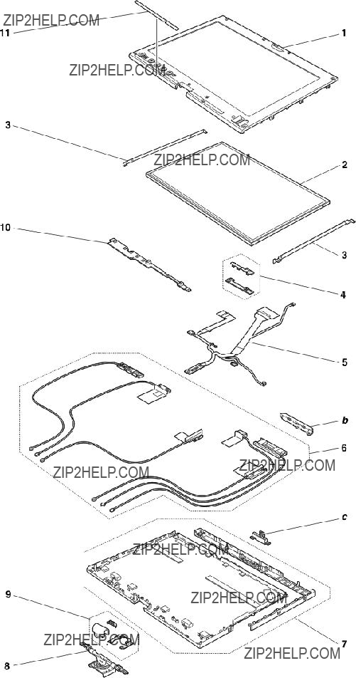
Chapter 10. Parts list 161
Table 39. Parts list -
162 ThinkPad X200 Tablet and X201 Tablet Hardware Maintenance Manual
Table 39. Parts list -
Chapter 10. Parts list 163
Table 39. Parts list -
164 ThinkPad X200 Tablet and X201 Tablet Hardware Maintenance Manual
Table 39. Parts list -
Chapter 10. Parts list 165
Table 39. Parts list -
166 ThinkPad X200 Tablet and X201 Tablet Hardware Maintenance Manual
Table 39. Parts list -
Chapter 10. Parts list 167
Table 39. Parts list -
168 ThinkPad X200 Tablet and X201 Tablet Hardware Maintenance Manual

Table 39. Parts list -
LCD FRUs for protection plate LCD
???
Chapter 10. Parts list 169
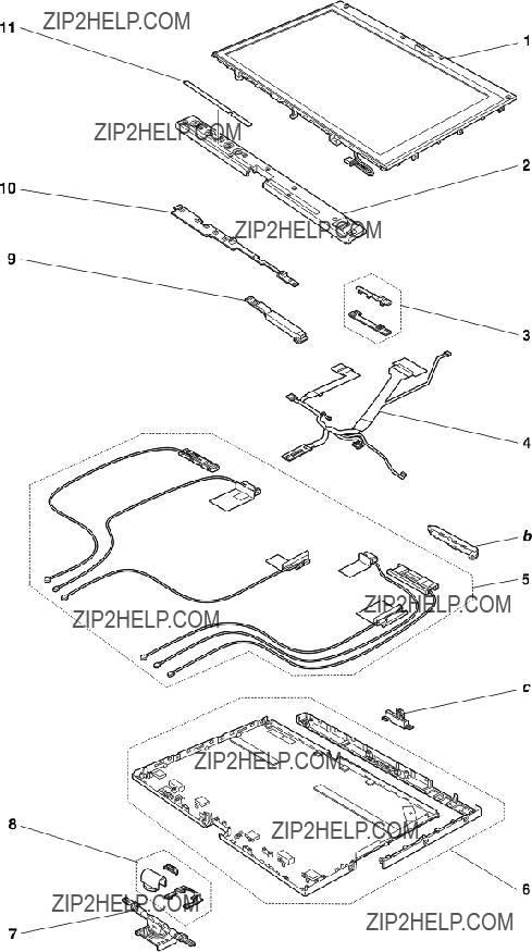
170 ThinkPad X200 Tablet and X201 Tablet Hardware Maintenance Manual
Table 40. Parts list -
Chapter 10. Parts list 171
Table 40. Parts list -
172 ThinkPad X200 Tablet and X201 Tablet Hardware Maintenance Manual
Table 40. Parts list -
Chapter 10. Parts list 173
Table 40. Parts list -
174 ThinkPad X200 Tablet and X201 Tablet Hardware Maintenance Manual
Table 40. Parts list -
Chapter 10. Parts list 175
Table 40. Parts list -
176 ThinkPad X200 Tablet and X201 Tablet Hardware Maintenance Manual

Table 40. Parts list -
Keyboard
Table 41. Parts list - Keyboard
Chapter 10. Parts list 177

Table 41. Parts list - Keyboard (continued)
Miscellaneous parts
Table 42. Parts list - Miscellaneous parts
???M1.6 ?? 6 mm (sliver), wafer head (1)
???M2 ?? 2.5 mm (black), wafer head (1)
???M2 ?? 3 mm (black), flat head (11)
???M2 ?? 3.5 mm (silver), wafer head (18)
???M2 ?? 3.5 mm (black), wafer head (1)
???M2 ?? 6 mm (silver), wafer head (3)
???M2 ?? 6 mm (black), wafer head (13)
???M2 ?? 3 mm, height 4.2 mm, stud (black) (1)
???M2 ?? 3 mm, height 5.5 mm, stud (black) (1)
???M2.5 ?? 6 mm (black), wafer head (6)
???M2.5 ?? 8 mm (black), wafer head (9)
???HDD screw M3 ?? 3 mm (black), wafer head (1)
???Screw cap, circle (9)
???Screw cap, square (6)
178 ThinkPad X200 Tablet and X201 Tablet Hardware Maintenance Manual
Table 42. Parts list - Miscellaneous parts (continued)
Chapter 10. Parts list 179
Table 42. Parts list - Miscellaneous parts (continued)
AC adapters
Table 43. Parts list - AC adapters
Power cords
A ThinkPad power cord for a specific country or region is usually available only in that country or region:
180 ThinkPad X200 Tablet and X201 Tablet Hardware Maintenance Manual

Table 44. Parts list -
Recovery discs
Windows XP Tablet DVDs (32 bit)
Windows XP Tablet (32 bit) is preinstalled as the operating system in the following models:
???
Chapter 10. Parts list 181

???
???
???
???
???
???
Table 46. Parts list - Windows XP Tablet (32 bit) recovery DVDs
???
???
???
???
???
???
???
182 ThinkPad X200 Tablet and X201 Tablet Hardware Maintenance Manual
Table 47. Parts list - Windows XP Tablet (32 bit) recovery DVDs
Windows Vista Home Premium (32 bit) DVDs
Windows Vista Home Premium (32 bit) is preinstalled as the operating system in the following models:
???
???
???
???
???
???
???
Table 48. Parts list - Windows Vista Home Premium (32 bit) DVDs
Chapter 10. Parts list 183

Table 48. Parts list - Windows Vista Home Premium (32 bit) DVDs (continued)
Windows Vista Business (32 bit) DVDs
Windows Vista Business (32 bit) is preinstalled as the operating system in the following models:
???
???
???
???
???
???
???
Table 49. Parts list - Windows Vista Business (32 bit) DVDs
184 ThinkPad X200 Tablet and X201 Tablet Hardware Maintenance Manual

Table 49. Parts list - Windows Vista Business (32 bit) DVDs (continued)
???
???
???
???
???
???
???
Table 50. Parts list - Windows Vista Business (32 bit) DVDs
Windows Vista Business (64 bit) DVDs
Windows Vista Business (64 bit) is preinstalled as the operating system in the following models:
???
???
???
???
???
???
???
Chapter 10. Parts list 185

Table 51. Parts list - Windows Vista Business (32 bit) DVDs
Windows Vista Ultimate (32 bit) DVDs
Windows Vista Ultimate (32 bit) is preinstalled as the operating system in the following models:
???
???
???
???
???
???
???
Table 52. Parts list - Windows Vista Ultimate (32 bit) DVDs
186 ThinkPad X200 Tablet and X201 Tablet Hardware Maintenance Manual

Table 52. Parts list - Windows Vista Ultimate (32 bit) DVDs (continued)
Windows 7 Home Basic (32 bit) DVDs
Windows 7 Home Basic (32 bit) is preinstalled as the operating system in the following models:
???
???
???
???
???
???
???
Table 53. Parts list - Windows 7 Home Basic (32 bit) DVDs
Windows 7 Home Premium (32 bit) DVDs
Windows 7 Home Premium (32 bit) is preinstalled as the operating system in the following models:
???
???
???
???
???
???
???
Chapter 10. Parts list 187

Table 54. Parts list - Windows 7 Home Premium (32 bit) DVDs
???
???
???
???
???
???
???
Table 55. Parts list - Windows 7 Home Premium (32 bit) DVDs
Windows 7 Home Premium (64 bit) DVDs
Windows 7 Home Premium (64 bit) is preinstalled as the operating system in the following models:
???
???
???
188 ThinkPad X200 Tablet and X201 Tablet Hardware Maintenance Manual

???
???
???
???
Table 56. Parts list - Windows 7 Home Premium (64 bit) DVDs
???
???
???
???
???
???
???
Table 57. Parts list - Windows 7 Home Premium (64 bit) DVDs
Windows 7 Professional (32 bit) DVDs
Windows 7 Professional (32 bit) is preinstalled as the operating system in the following models:
???
???
???
???
???
Chapter 10. Parts list 189

???
???
???
190 ThinkPad X200 Tablet and X201 Tablet Hardware Maintenance Manual

???
???
???
???
Table 59. Parts list - Windows 7 Professional (32 bit) DVDs
Chapter 10. Parts list 191

Windows 7 Professional (64 bit) DVDs
Windows 7 Professional (64 bit) is preinstalled as the operating system in the following models:
???
???
???
???
???
???
???
Table 60. Parts list - Windows 7 Professional (64 bit) DVDs
???
???
???
???
???
???
???
Table 61. Parts list - Windows 7 Professional (64 bit) DVDs
192 ThinkPad X200 Tablet and X201 Tablet Hardware Maintenance Manual
Table 61. Parts list - Windows 7 Professional (64 bit) DVDs (continued)
Common service tools
Table 62. Parts
Notices
Lenovo may not offer the products, services, or features discussed in this document in all countries. Consult your local Lenovo representative for information on the products and services currently available in your area. Any reference to a Lenovo product, program, or service is not intended to state or imply that only that Lenovo product, program, or service may be used. Any functionally equivalent product, program, or service that does not infringe any Lenovo intellectual property right may be used instead. However, it is the user's responsibility to evaluate and verify the operation of any other product, program, or service.
Lenovo may have patents or pending patent applications covering subject matter described in this document. The furnishing of this document does not give you any license to these patents. You can send license inquiries, in writing, to:
Lenovo (United States), Inc.
1009 Think Place - Building One
Morrisville, NC 27560
U.S.A.
Attention: Lenovo Director of Licensing
LENOVO PROVIDES THIS PUBLICATION ???AS IS??? WITHOUT WARRANTY OF ANY KIND, EITHER EXPRESS
OR IMPLIED, INCLUDING, BUT NOT LIMITED TO, THE IMPLIED WARRANTIES OF
Chapter 10. Parts list 193

disclaimer of express or implied warranties in certain transactions, therefore, this statement may not apply to you.
This information could include technical inaccuracies or typographical errors. Changes are periodically made to the information herein; these changes will be incorporated in new editions of the publication. Lenovo may make improvements and/or changes in the product(s) and/or the program(s) described in this publication at any time without notice.
The products described in this document are not intended for use in implantation or other life support applications where malfunction may result in injury or death to persons. The information contained in this document does not affect or change Lenovo product specifications or warranties. Nothing in this document shall operate as an express or implied license or indemnity under the intellectual property rights of Lenovo or third parties. All information contained in this document was obtained in specific environments and is presented as an illustration. The result obtained in other operating environments may vary.
Lenovo may use or distribute any of the information you supply in any way it believes appropriate without incurring any obligation to you.
Any references in this publication to
Any performance data contained herein was determined in a controlled environment. Therefore, the result obtained in other operating environments may vary significantly. Some measurements may have been made on
Trademarks
The following terms are trademarks of Lenovo in the United States, other countries or both:
Active Protection System
Lenovo
Rescue and Recovery
ThinkPad
ThinkVantage
TrackPoint
UltraBase
Ultrabay
UltraNav
IBM?? (used under license) is trademark of the International Business Machines Corporation in the United States, other countries, or both:
Windows and Windows Vista are trademarks of Microsoft Corporation in the United States, other countries, or both.
The following are trademarks of Intel Corporation or its subsidiaries in the United States, other countries, or both:
Intel
Intel Celeron
Intel Core 2 Duo
194 ThinkPad X200 Tablet and X201 Tablet Hardware Maintenance Manual
Intel Core 2 Solo
Other company, product, or service names may be the trademarks or service marks of others.
Chapter 10. Parts list 195
196 ThinkPad X200 Tablet and X201 Tablet Hardware Maintenance Manual
Part Number: 45N3683_03
Printed in China
(1P) P/N: 45N3683_03
*45N3683_03*