ThinkStation
Hardware Maintenance Manual
Machine Types: 4223, 4228 and 4229
ThinkStation
Hardware Maintenance Manual
Machine Types: 4223, 4228 and 4229

ThinkStation
Hardware Maintenance Manual
Machine Types: 4223, 4228 and 4229
Note: Before using this information and the product it supports, be sure to read and understand the Chapter 2 ???Safety information??? on page 3 and Appendix A ???Notices??? on page 109.
First Edition (April 2012)
?? Copyright Lenovo 2012.
LIMITED AND RESTRICTED RIGHTS NOTICE: If data or software is delivered pursuant a General Services Administration ???GSA??? contract, use, reproduction, or disclosure is subject to restrictions set forth in Contract No.

Contents
iv ThinkStation Hardware Maintenance Manual

Chapter 1. About this manual
This manual provides service and reference information for ThinkStation?? computers listed on the front cover. This manual is intended only for trained service personnel who are familiar with Lenovo?? computer products.
Before servicing a Lenovo computer product, be sure to read Chapter 2 ???Safety information??? on page 3.
Chapter 8
For major Field Replaceable Unit (FRU) locations and Customer Replaceable Unit (CRU) identification, see Chapter 9 ???Locations??? on page 55.
For FRU replacement instructions, see Chapter 10 ???Replacing FRUs??? on page 63.
For FRU part numbers, go to:
Important Safety Information
Be sure to read all caution and danger statements in this book before performing any of the instructions.
Veuillez lire toutes les consignes de type DANGER et ATTENTION du pr??sent document avant d'ex??cuter les instructions.
Lesen Sie unbedingt alle Hinweise vom Typ "ACHTUNG" oder "VORSICHT" in dieser Dokumentation, bevor Sie irgendwelche Vorg??nge durchf??hren
Leggere le istruzioni introdotte da ATTENZIONE e PERICOLO presenti nel manuale prima di eseguire una qualsiasi delle istruzioni
Es importante que lea todas las declaraciones de precauci??n y de peligro de este manual antes de seguir las instrucciones.
2 ThinkStation Hardware Maintenance Manual
Chapter 2. Safety information
This chapter contains the safety information that you need to be familiar with before servicing a computer.
General safety
Follow these rules to ensure general safety:
???Observe good housekeeping in the area of the machines during and after maintenance.
???When lifting any heavy object:
1.Ensure you can stand safely without slipping.
2.Distribute the weight of the object equally between your feet.
3.Use a slow lifting force. Never move suddenly or twist when you attempt to lift.
4.Lift by standing or by pushing up with your leg muscles; this action removes the strain from the muscles in your back. Do not attempt to lift any objects that weigh more than 16 kg (35 lb) or objects that you think are too heavy for you.
???Do not perform any action that causes hazards to the customer, or that makes the equipment unsafe.
???Before you start the machine, ensure that other service representatives and the customer's personnel are not in a hazardous position.
???Place removed covers and other parts in a safe place, away from all personnel, while you are servicing the machine.
???Keep your tool case away from walk areas so that other people will not trip over it.
???Do not wear loose clothing that can be trapped in the moving parts of a machine. Ensure that your sleeves are fastened or rolled up above your elbows. If your hair is long, fasten it.
???Insert the ends of your necktie or scarf inside clothing or fasten it with a nonconductive clip, approximately 8 centimeters (3 inches) from the end.
???Do not wear jewelry, chains,
???Wear safety glasses when you are: hammering, drilling, soldering, cutting wire, attaching springs, using solvents, or working in any other conditions that might be hazardous to your eyes.
???After service, reinstall all safety shields, guards, labels, and ground wires. Replace any safety device that is worn or defective.
???Reinstall all covers correctly before returning the machine to the customer.
Electrical safety
CAUTION:
Electrical current from power, telephone, and communication cables can be hazardous. To avoid personal injury or equipment damage, disconnect the attached power cords, telecommunication systems, networks, and modems before you open the server/workstation covers, unless instructed otherwise in the installation and configuration procedures.
Observe the following rules when working on electrical equipment.
Important: Use only approved tools and test equipment. Some hand tools have handles covered with a soft material that does not insulate you when working with live electrical currents. Many customers have, near their equipment, rubber floor mats that contain small conductive fibers to decrease electrostatic discharges. Do not use this type of mat to protect yourself from an electric shock.
???Find the room emergency
???Do not work alone under hazardous conditions or near equipment that has hazardous voltages.
???Disconnect all power before:
???Performing a mechanical inspection
???Working near power supplies
???Removing or installing FRU
???Before you start to work on the machine, unplug the power cord. If you cannot unplug it, ask the customer to
???If you need to work on a machine that has exposed electrical circuits, observe the following precautions:
???Ensure that another person, familiar with the
???Use only one hand when working with
Remember: There must be a complete circuit to cause an electric shock. By observing the above rule, you may prevent a current from passing through your body.
???When using a tester, set the controls correctly and use the approved probe leads and accessories for that tester.
???Stand on suitable rubber mats (obtained locally, if necessary) to insulate you from grounds such as metal floor strips and machine frames.
Observe the special safety precautions when you work with very high voltages; these instructions are in the safety sections of maintenance information. Use extreme care when measuring high voltages.
???Regularly inspect and maintain your electrical hand tools for safe operational condition.
???Do not use worn or broken tools and testers.
???Never assume that power has been disconnected from a circuit. First, check that it has been
???Always look carefully for possible hazards in your work area. Examples of these hazards are moist floors, nongrounded power extension cables, power surges, and missing safety grounds.
???Do not touch live electrical circuits with the reflective surface of a plastic dental mirror. The surface is conductive; such touching can cause personal injury and machine damage.
???Do not service the following parts with the power on when they are removed from their normal operating places in a machine:
???Power supply units
???Pumps
???Blowers and fans
???Motor generators
and similar units. (This practice ensures correct grounding of the units.)
???If an electrical accident occurs:
???Use caution; do not become a victim yourself.
???Switch off power.
???Send another person to get medical aid.
4 ThinkStation Hardware Maintenance Manual
Some computers are equipped with a
CAUTION:
You must know the voltage of the electrical connection (outlet) where your computer will be connected. If you do not know the voltage, contact your local electric company or refer to official Web sites or other literature for travelers to the country or region where you are located.
If your computer has a
outlet until you have verified that the
If your computer does not have a
???If the
???If the
Safety inspection guide
The intent of this inspection guide is to assist you in identifying potentially unsafe conditions on these products. Each machine, as it was designed and built, had required safety items installed to protect users and service personnel from injury. This guide addresses only those items. However, good judgment should be used to identify potential safety hazards due to attachment of features or options not covered by this inspection guide.
If any unsafe conditions are present, you must determine how serious the apparent hazard could be and whether you can continue without first correcting the problem.
Consider these conditions and the safety hazards they present:
???Electrical hazards, especially primary power (primary voltage on the frame can cause serious or fatal electrical shock).
???Explosive hazards, such as a damaged CRT face or bulging capacitor
???Mechanical hazards, such as loose or missing hardware
The guide consists of a series of steps presented in a checklist. Begin the checks with the power off, and the power cord disconnected.
Checklist:
1.Check exterior covers for damage (loose, broken, or sharp edges).
2.
Chapter 2. Safety information 5

3.Check the power cord for:
a.A
b.The power cord should be the appropriate type as specified in the parts listings.
c.Insulation must not be frayed or worn.
4.Remove the cover.
5.Check for any obvious alterations. Use good judgment as to the safety of any alterations.
6.Check inside the unit for any obvious unsafe conditions, such as metal filings, contamination, water or other liquids, or signs of fire or smoke damage.
7.Check for worn, frayed, or pinched cables.
8.Check that the
Handling electrostatic
Any computer part containing transistors or integrated circuits (ICs) should be considered sensitive to electrostatic discharge (ESD). ESD damage can occur when there is a difference in charge between objects. Protect against ESD damage by equalizing the charge so that the machine, the part, the work mat, and the person handling the part are all at the same charge.
Notes:
1.Use
2.Make sure that the ESD protective devices you use have been certified (ISO 9000) as fully effective.
When handling
???Keep the parts in protective packages until they are inserted into the product.
???Avoid contact with other people while handling the part.
???Wear a grounded wrist strap against your skin to eliminate static on your body.
???Prevent the part from touching your clothing. Most clothing is insulative and retains a charge even when you are wearing a wrist strap.
???Use the black side of a grounded work mat to provide a
???Select a grounding system, such as those listed below, to provide protection that meets the specific service requirement.
Note: The use of a grounding system is desirable but not required to protect against ESD damage.
???Attach the ESD ground clip to any frame ground, ground braid, or
???Use an ESD common ground or reference point when working on a
???Use the round
Grounding requirements
Electrical grounding of the computer is required for operator safety and correct system function. Proper grounding of the electrical outlet can be verified by a certified electrician.
Safety notices
The caution and danger safety notices in this section are provided in the following languages:
6 ThinkStation Hardware Maintenance Manual

???English
???Arabic
???Brazilian/Portuguese
???Chinese (simplified)
???Chinese (traditional)
???French
???German
???Hebrew
???Italian
???Korean
???Spanish
DANGER
Electrical current from power, telephone and communication cables is hazardous.
To avoid a shock hazard:
???Do not connect or disconnect any cables or perform installation, maintenance, or reconfiguration of this product during an electrical storm.
???Connect all power cords to a properly wired and grounded electrical outlet.
???Connect to properly wired outlets any equipment that will be attached to this product.
???When possible, use one hand only to connect or disconnect signal cables.
???Never turn on any equipment when there is evidence of fire, water, or structural damage.
???Disconnect the attached power cords, telecommunications systems, networks, and modems before you open the device covers, unless instructed otherwise in the installation and configuration procedures.
???Connect and disconnect cables as described in the following tables when installing, moving, or opening covers on this product or attached devices.
CAUTION:
When replacing the lithium battery, use only Part Number 45C1566 or an equivalent type battery recommended by the manufacturer. If your system has a module containing a lithium battery, replace
Chapter 2. Safety information 7

it only with the same module type made by the same manufacturer. The battery contains lithium and can explode if not properly used, handled, or disposed of. Do not:
???Throw or immerse into water
???Heat to more than 100??C (212??F)
???Repair or disassemble
Dispose of the battery as required by local ordinances or regulations.
CAUTION:
When laser products (such as
???Do not remove the covers. Removing the covers of the laser product could result in exposure to hazardous laser radiation. There are no serviceable parts inside the device.
???Use of controls or adjustments or performance of procedures other than those specified herein might result in hazardous radiation exposure.
 DANGER
Some laser products contain an embedded Class 3A or Class 3B laser diode. Note the following:
Laser radiation when open. Do not stare into the beam, do not view directly with optical instruments, and avoid direct exposure to the beam.
CAUTION:
Use safe practices when lifting.
CAUTION:
The power control button on the device and the power switch on the power supply do not turn off the electrical current supplied to the device. The device also might have more than one power cord. To remove all electrical current from the device, ensure that all power cords are disconnected from the power source.
8 ThinkStation Hardware Maintenance Manual
2 


 1
1 


Chapter 2. Safety information 9

10 ThinkStation Hardware Maintenance Manual

2 


 1
1 


PERIGO
A corrente el??trica proveniente de cabos de alimenta????o, de telefone e de comunica????es ?? perigosa.
Para evitar risco de choque el??trico:
???N??o conecte nem desconecte nenhum cabo ou execute instala????o, manuten????o ou reconfigura????o deste produto durante uma tempestade com raios.
???Conecte todos os cabos de alimenta????o a tomadas el??tricas corretamente instaladas e aterradas.
???Todo equipamento que for conectado a este produto deve ser conectado a tomadas corretamente instaladas.
???Quando poss??vel, utilize apenas uma das m??os para conectar ou desconectar cabos de sinal.
???Nunca ligue nenhum equipamento quando houver evid??ncia de fogo, ??gua ou danos estruturais.
???Antes de abrir tampas de dispositivos, desconecte cabos de alimenta????o, sistemas de telecomunica????o, redes e modems conectados, a menos que especificado de maneira diferente nos procedimentos de instala????o e configura????o.
???Conecte e desconecte os cabos conforme descrito na tabela apresentada a seguir ao instalar, mover ou abrir tampas deste produto ou de dispositivos conectados.
CUIDADO:
Ao substituir a bateria de l??tio, utilize apenas uma bateria com N??mero de Pe??a 45C1566 ou um tipo de bateria equivalente recomendado pelo Se o seu sistema possui um m??dulo com uma bateria de l??tio,
Chapter 2. Safety information 11

N??o:
???Jogue ou coloque na ??gua
???Aque??a a mais de 100??C (212??F)
???Conserte nem desmonte
Descarte a bateria conforme requerido pelas leis ou regulamentos locais.
PRECAUCI??N:
Quando produtos a laser (como unidades de
???N??o remova as tampas. A remo????o das tampas de um produto a laser pode resultar em exposi????o prejudicial ?? radia????o de laser. N??o existem pe??as que podem ser consertadas no interior do dispositivo.
???A utiliza????o de controles ou ajustes ou a execu????o de procedimentos diferentes dos especificados aqui pode resultar em exposi????o prejudicial ?? radia????o.
PERIGO
Alguns produtos a laser cont??m diodo de laser integrado da Classe 3A ou da Classe 3B. Observe o seguinte:
Radia????o a laser quando aberto. N??o olhe diretamente para o feixe a olho nu ou com instrumentos ??pticos e evite exposi????o direta ao feixe.
CUIDADO:
Utilize procedimentos de seguran??a para levantar equipamentos.
CUIDADO:
O bot??o de controle de alimenta????o do dispositivo e o bot??o para ligar/desligar da fonte de alimenta????o n??o desligam a corrente el??trica fornecida ao dispositivo. O dispositivo tamb??m pode ter mais de um cabo de alimenta????o. Para remover toda a corrente el??trica do dispositivo, assegure que todos os cabos de alimenta????o estejam desconectados da fonte de alimenta????o.
12 ThinkStation Hardware Maintenance Manual
2 


 1
1 


Chapter 2. Safety information 13

2 


 1
1 


14 ThinkStation Hardware Maintenance Manual
Chapter 2. Safety information 15
2 


 1
1 


DANGER
Le courant ??lectrique provenant de l'alimentation, du t??l??phone et des c??bles de transmission peut pr??senter un danger.
Pour ??viter tout risque de choc ??lectrique :
???Ne manipulez aucun c??ble et n'effectuez aucune op??ration d'installation, d'entretien ou de reconfiguration de ce produit au cours d'un orage.
???Branchez tous les cordons d'alimentation sur un socle de prise de courant correctement c??bl?? et mis ?? la terre.
???Branchez sur des socles de prise de courant correctement c??bl??s tout ??quipement connect?? ?? ce produit.
???Lorsque cela est possible, n'utilisez qu'une seule main pour connecter ou d??connecter les c??bles d'interface.
???Ne mettez jamais un ??quipement sous tension en cas d'incendie ou d'inondation, ou en pr??sence de dommages mat??riels.
???Avant de retirer les carters de l'unit??, mettez
???Lorsque vous installez, que vous d??placez, ou que vous manipulez le pr??sent produit ou des p??riph??riques qui lui sont raccord??s,
16 ThinkStation Hardware Maintenance Manual

ATTENTION:
Remplacer la pile au lithium usag??e par une pile de r??f??rence identique exclusivement, (r??f??rence 45C1566), ou suivre les instructions du fabricant qui en d??finit les ??quivalences. Si votre syst??me est dot?? d'un module contenant une pile au lithium, vous devez le remplacer uniquement par un module identique, produit par le m??me fabricant. La pile contient du lithium et peut exploser en cas de mauvaise utilisation, de mauvaise manipulation ou de mise au rebut inappropri??e.
Ne pas :
???la jeter ?? l'eau,
???l'exposer ?? des temp??ratures sup??rieures ?? 100??C,
???chercher ?? la r??parer ou ?? la d??monter.
Ne pas mettre la pile ?? la poubelle. Pour la mise au rebut, se reporter ?? la r??glementation en vigueur.
ATTENTION:
Si des produits ?? laser (tels que des unit??s de
???Ne retirez pas le carter. En ouvrant l'unit?? de
???Pour ??viter tout risque d'exposition au rayon laser, respectez les consignes de r??glage et d'utilisation des commandes, ainsi que les proc??dures d??crites dans le pr??sent manuel.
DANGER
Certains produits ?? laser contiennent une diode ?? laser int??gr??e de classe 3A ou 3B. Prenez connaissance des informations suivantes:
Rayonnement laser lorsque le carter est ouvert. Evitez toute expositiondirecte au rayon laser. Evitez de regarder fixement le faisceau ou del'observer ?? l'aide d'instruments optiques.
Chapter 2. Safety information 17
ATTENTION:
Soulevez la machine avec pr??caution.
ATTENTION:
L'interrupteur de contr??le d'alimentation de l'unit?? et l'interrupteur dubloc d'alimentation ne coupent pas le courant ??lectrique alimentantl'unit??. En outre, le syst??me peut ??tre ??quip?? de plusieurs cordonsd'alimentation. Pour mettre l'unit?? hors tension, vous devez d??connectertous les cordons de la source d'alimentation.
2 


 1
1 


VORSICHT
An
Aus Sicherheitsgr??nden:
???Bei Gewitter an diesem Ger??t keine Kabel anschlie??en oder l??sen. Ferner keine
???Ger??t nur an eine Schutzkontaktsteckdose mit ordnungsgem???? geerdetem Schutzkontakt anschlie??en.
???Alle angeschlossenen Ger??te ebenfalls an Schutzkontaktsteckdosen mit ordnungsgem???? geerdetem Schutzkontakt anschlie??en.
???Die Signalkabel nach M??glichkeit einh??ndig anschlie??en oder l??sen, um einen Stromschlag durch Ber??hren von Oberfl??chen mit unterschiedlichem elektrischem Potenzial zu vermeiden.
???Ger??te niemals einschalten, wenn Hinweise auf Feuer, Wasser oder Geb??udesch??den vorliegen.
18 ThinkStation Hardware Maintenance Manual

???Die Verbindung zu den angeschlossenen Netzkabeln, Telekommunikationssystemen, Netzwerken und Modems ist vor dem ??ffnen des Geh??uses zu unterbrechen, sofern in den Installations- und Konfigurationsprozeduren keine anders lautenden Anweisungen enthalten sind.
???Zum Installieren, Transportieren und ??ffnen der Abdeckungen des Computers oder der angeschlossenen Einheiten die Kabel gem???? der folgenden Tabelle anschlie??en und abziehen.
CAUTION:
Eine verbrauchte Lithiumbatterie nur durch eine Batterie mit der Teilenummer 45C1566 oder eine gleichwertige, vom Hersteller empfohlene Batterie ersetzen. Enth??lt das System ein Modul mit einer Lithiumbatterie, dieses nur durch ein Modul desselben Typs und von demselben Hersteller ersetzen. Die Batterie enth??lt Lithium und kann bei unsachgem????er Verwendung, Handhabung oder Entsorgung explodieren.
Die Batterie nicht:
???mit Wasser in Ber??hrung bringen.
?????ber 100 C erhitzen.
???reparieren oder zerlegen.
Die ??rtlichen Bestimmungen f??r die Entsorgung von Sonderm??ll beachten.
ACHTUNG:
Bei der Installation von Laserger??ten (wie
???Die Abdeckungen nicht entfernen. Durch Entfernen der Abdeckungen des Laserger??ts k??nnen gef??hrliche Laserstrahlungen freigesetzt werden. Das Ger??t enth??lt keine zu wartenden Teile.
???Werden Steuerelemente, Einstellungen oder Durchf??hrungen von Prozeduren anders als hier angegeben verwendet, kann gef??hrliche Laserstrahlung auftreten.
VORSICHT
Einige Laserger??te enthalten eine Laserdiode der Klasse 3A oder 3B. Beachten Sie Folgendes:
Chapter 2. Safety information 19

Laserstrahlung bei ge??ffneter Verkleidung. Nicht in den Strahl blicken. Keine Lupen oder Spiegel verwenden. Strahlungsbereich meiden.
ACHTUNG:
Arbeitsschutzrichtlinien beim Anheben der Maschine beachten.
ACHTUNG:
Mit dem Netzschalter an der Einheit und am Netzteil wird die Stromversorgung f??r die Einheit nicht unterbrochen. Die Einheit kann auch mit mehreren Netzkabeln ausgestattet sein. Um die Stromversorgung f??r die Einheit vollst??ndig zu unterbrechen, m??ssen alle zum Ger??t f??hrenden Netzkabel vom Netz getrennt werden.
2 


 1
1 


20 ThinkStation Hardware Maintenance Manual

Chapter 2. Safety information 21

2 


 1
1 


PERICOLO
La corrente elettrica proveniente dai cavi di alimentazione, del telefono e di comunicazione pu?? essere pericolosa.
Per evitare il rischio di scosse elettriche:
???Non collegare o scollegare qualsiasi cavo oppure effettuare l'installazione, la manutenzione o la riconfigurazione del prodotto durante un temporale.
???Collegare tutti i fili elettrici a una presa di alimentazione correttamente cablata e dotata di messa a terra.
???Collegare alle prese elettriche appropriate tutte le apparecchiature che verranno utilizzate per questo prodotto.
22 ThinkStation Hardware Maintenance Manual

???Se possibile, utilizzare solo una mano per collegare o scollegare i cavi di segnale.
???Non accendere assolutamente apparecchiature in presenza di incendi, perdite d'acqua o danno strutturale.
???Scollegare i cavi di alimentazione, i sistemi di telecomunicazione, le reti e il modem prima di aprire i coperchi del dispositivo, salvo istruzioni contrarie relative alle procedure di installazione e configurazione.
???Collegare e scollegare i cavi come descritto nella seguente tabella quando vengono effettuate operazioni di installazione, spostamento o apertura dei coperchi di questo prodotto o delle unit?? collegate.
ATTENZIONE:
Quando si sostituisce la batteria al litio, utilizzare solo il Numero parte 45C1566 o un tipo di batteria equivalente consigliato dal produttore. Se sul sistema ?? presente un modulo che contiene una batteria al litio, sostituirlo solo con un tipo di modulo dello stesso tipo della stessa casa di produzione. La batteria contiene litio e pu?? esplodere se usata, maneggiata o smaltita in modo non corretto.
Non:
???Gettare o immergere la batteria nell'acqua
???Riscaldarla ad una temperatura superiore ai 100 gradi C (212 gradi F)
???Smontarla, ricaricarla o tentare di ripararla
Le batterie usate vanno smaltite in accordo alla normativa in vigore (DPR 915/82 e successive disposizioni e disposizioni locali).
ATTENZIONE:
Quando vengono installati prodotti laser (quali
???Non rimuovere gli sportelli. L'apertura di un'unit?? laser pu?? determinare l'esposizione a radiazioni laser pericolose. All'interno dell'unit?? non vi sono parti su cui effettuare l'assistenza tecnica.
???L'utilizzo di controlli, regolazioni o l'esecuzione di procedure non descritti nel presente manuale possono provocare l'esposizione a radiazioni pericolose.
Chapter 2. Safety information 23

PERICOLO
Alcune unit?? laser contengono un diodo laser di Classe 3A o Classe 3B. Tener presente quanto segue:
Aprendo l'unit?? vengono emesse radiazioni laser. Non fissare il fascio, non guardarlo direttamente con strumenti ottici ed evitare l'esposizione al fascio.
ATTENZIONE:
Prestare attenzione nel sollevare l'apparecchiatura.
ATTENZIONE:
Il pulsante di controllo dell'alimentazione presente sull'unit?? e l'interruttore dell'alimentatore non disattivano l'alimentazione corrente fornita all'unit??. E' possibile che l'unit?? disponga di pi?? cavi di alimentazione. Per disattivare l'alimentazione dall'unit??, accertarsi che tutti i cavi di alimentazione siano scollegati dalla fonte di alimentazione.
2 


 1
1 


24 ThinkStation Hardware Maintenance Manual
Chapter 2. Safety information 25

2 


 1
1 


PELIGRO
La corriente el??ctrica procedente de cables de alimentaci??n, tel??fonos y cables de comunicaci??n puede ser peligrosa.
Para evitar el riesgo de descarga el??ctrica:
???No conecte ni desconecte los cables ni realice ninguna tarea de instalaci??n, mantenimiento o reconfiguraci??n de este producto durante una tormenta el??ctrica.
???Conecte todos los cables de alimentaci??n a tomas de corriente debidamente cableadas y conectadas a tierra.
???Cualquier equipo que se conecte a este producto tambi??n debe conectarse a tomas de corriente debidamente cableadas.
???Siempre que sea posible, utilice una sola mano para conectar o desconectar los cables de se??al.
???No encienda nunca un equipo cuando hay se??ales de fuego, agua o da??os estructurales.
26 ThinkStation Hardware Maintenance Manual

???Desconecte los cables de alimentaci??n, los sistemas de telecomunicaciones, las redes y los m??dems conectados antes de abrir las cubiertas de los dispositivos, a menos que se indique lo contrario en los procedimientos de instalaci??n y configuraci??n.
???Conecte y desconecte los cables, como se describe en la tabla siguiente, cuando instale, mueva o abra las cubiertas de este producto o de los dispositivos conectados.
PRECAUCI??N:
Cuando sustituya una bater??a de litio, utilice solamente una bater??a n??mero de pieza 45C1566 u otra de tipo equivalente recomendada por el fabricante. Si su sistema dispone de un m??dulo que contiene una bater??a de litio, reempl??celo s??lo con el mismo tipo de m??dulo, del mismo fabricante. La bater??a contiene litio y puede explotar si no se utiliza, manipula o desecha correctamente.
No debe:
???Arrojarla al agua o sumergirla en ella
???Exponerla a temperaturas superiores a 100??C (212??F)
???Repararla o desmontarla
Desh??gase de la bater??a seg??n especifiquen las leyes o normas locales.
PRECAUCI??N:
Cuando haya productos l??ser (como unidades de
???No quite las cubiertas. Si quita las cubiertas del producto l??ser, podr??a quedar expuesto a radiaci??n l??ser peligrosa. Dentro del dispositivo no existe ninguna pieza que requiera servicio t??cnico.
???Si usa controles o ajustes o realiza procedimientos que no sean los especificados aqu??, podr??a exponerse a radiaciones peligrosas.
PELIGRO
Chapter 2. Safety information 27
Algunos productos l??ser tienen incorporado un diodo l??ser de clase 3A o clase 3B. Tenga en cuenta lo siguiente:
Cuando se abre, queda expuesto a radiaci??n l??ser. No mire directamente al rayo l??ser, ni siquiera con instrumentos ??pticos, y evite exponerse directamente al rayo l??ser.
PRECAUCI??N:
Adopte procedimientos seguros al levantar el equipo.
PRECAUCI??N:
El bot??n de control de alimentaci??n del dispositivo y el interruptor de alimentaci??n de la fuente de alimentaci??n no desconectan la corriente el??ctrica suministrada al dispositivo. Adem??s, el dispositivo podr??a tener m??s de un cable de alimentaci??n. Para suprimir toda la corriente el??ctrica del dispositivo, aseg??rese de que todos los cables de alimentaci??n est??n desconectados de la toma de corriente.
2 


 1
1 


28 ThinkStation Hardware Maintenance Manual
Chapter 3. General information
This chapter provides general information that applies to all machine types supported by this publication.
Specifications
This section lists the physical specifications for your computer.
Dimensions
Width: 210 mm (8.3 inches)
Height: 485 mm (19.1 inches) (floor to top of handle)
Depth: 602 mm (23.7 inches)
Weight
Maximum configuration as shipped: 27.5 kg (60.5 lbs)
Environment
??? Air temperature:
Operating: 10??C to 35??C (50??F to 95??F)
Storage:
Storage:
Note: The allowable upper temperature limit decreases by 1??C (1.8??F) for every 300 m (1000 ft) above sea level.
??? Humidity:
Operating: 10% to 80%
Storage: 10% to 90%
??? Altitude:
Supported altitude: (unpressurized):
Electrical input
???Input voltage:
??? Low range:
Minimum: 100 V ac
Maximum: 127 V ac
Input frequency range: 50 to 60 Hz
??? High range:
Minimum: 200 V ac
Maximum: 240 V ac
Input frequency range: 50 to 60 Hz
Lenovo ThinkVantage Tools
The Lenovo ThinkVantage?? Tools program guides you to a host of information sources and provides easy access to various tools to help you work more easily and securely.
To access the Lenovo ThinkVantage Tools program, click Start ??? All Programs ??? Lenovo ThinkVantage Tools.
The following table lists the programs that you can access from the Lenovo ThinkVantage Tools program. To access a program,
Table 1. Program icon names in Lenovo ThinkVantage Tools
Lenovo Solution Center
The Lenovo Solution Center program enables you to troubleshoot and resolve computer problems. It combines diagnostic tests, system information collection, security status, and support information, along with hints and tips for maximum system performance. See ???Lenovo Solution Center??? on page 35 for detailed information.
Lenovo Welcome
The Lenovo Welcome program introduces some innovative
Note: The Lenovo Welcome program is only available on computers preinstalled with the Windows 7 operating system from Lenovo.
Product Recovery
The Product Recovery program enables you to restore the contents of the hard disk drive to the factory default settings.
SimpleTap
The SimpleTap program provides you with a quick way to customize some basic computer settings such as muting the speakers, adjusting the volume, locking the computer operating system, launching a program, opening a Web page, opening a file, and so on. You also can use the SimpleTap program to access the Lenovo App Shop, from which you can download various applications and computer software.
To start the SimpleTap program in a quick way, do any of the following:
???Click the red SimpleTap launch point on the desktop. The red launch point is available on the desktop after you have launched the SimpleTap program for the first time.
???Press the blue ThinkVantage button if your keyboard has one.
Note: The SimpleTap program is only available on certain models preinstalled with the Windows 7 operating system. If your Windows 7 model is not preinstalled with the SimpleTap program, you can download it from http://www.lenovo.com/support.
ThinkVantage Rescue and Recovery
The ThinkVantage Rescue and Recovery program is a one button recovery and restore solution that includes a set of
30 ThinkStation Hardware Maintenance Manual

Note: If the Enhanced Backup and Restore icon in the Lenovo ThinkVantage Tools program is dimmed, it indicates that you need to install the ThinkVantage Rescue and Recovery program manually before enabling its features. To install the ThinkVantage Rescue and Recovery program, do the following:
1.Click Start ??? All Programs ??? Lenovo ThinkVantage Tools, and
2.Follow the instructions on the screen.
3.When the installation process completes, the Enhanced Backup and Restore icon is activated.
Additional information resources
If you have Internet access, the most
You can find the following information:
???Customer Replaceable Unit (CRU) installation or replacement instructions
???Downloads and drivers
???Parts information
???Publications
???Troubleshooting information
???Links to other useful sources of information
Chapter 3. General information 31
32 ThinkStation Hardware Maintenance Manual

Chapter 4. General Checkout
Attention
The drives in the computer you are servicing might have been rearranged or the drive startup sequence might have been changed. Be extremely careful during write operations such as copying, saving, or formatting. Data or programs can be overwritten if you select an incorrect drive.
General error messages appear if a problem or conflict is found by an application program, the operating system, or both. For an explanation of these messages, refer to the information supplied with that software package.
Before replacing a FRU, ensure that the latest level of BIOS is installed on the system. A
Use the following procedure to help determine the cause of a problem:
1.Turn off the computer and all external devices.
2.Check all cables and power cords.
3.Set all display controls to the middle position.
4.Turn on all external devices.
5.Turn on the computer.
???Look for displayed error codes
???Listen for beep codes
???Look for readable instructions or a main menu on the display.
If you did not receive the correct response, proceed to step 6 on page 33.
If you do receive the correct response, proceed to step 7 on page 33.
6.Look at the following conditions and follow the instructions:
???If you hear beep codes during POST, go to ???Beep symptoms??? on page 49.
???If the computer displays a POST error, go to ???POST error codes??? on page 50.
???If the computer hangs and no error is displayed, continue at step 7 on page 33.
7.Run the Diagnostic programs. See Chapter 5 ???Diagnostics??? on page 35.
???If the test stops and you cannot continue, replace the last device tested.
Problem determination tips
Due to the variety of hardware and software combinations that can be encountered, use the following information to assist you in problem determination. If possible, have this information available when requesting assistance from Service Support and Engineering functions.
???Machine type and model
???Processor or hard disk drive upgrades
???Failure symptom
???Do diagnostics indicate a failure?
???What, when, where, single, or multiple systems?
???Is the failure repeatable?
???Has this configuration ever worked?
???If it has been working, what changes were made prior to it failing?
???Is this the original reported failure?
???Diagnostics version
???Type and version level
???Hardware configuration
???Print (print screen) configuration currently in use
???BIOS level
???Operating system software
???Type and version level
Notes: To eliminate confusion, identical systems are considered identical only if they:
1.Are the exact machine type and models
2.Have the same BIOS level
3.Have the same adapters/attachments in the same locations
4.Have the same address jumpers/terminators/cabling
5.Have the same software versions and levels
6.Have the same diagnostic diskettes (version)
7.Have the same configuration options set in the system
8.Have the same setup for
Comparing the configuration and software
34 ThinkStation Hardware Maintenance Manual
Chapter 5. Diagnostics
The diagnostic program is used to test hardware components of your computer. The diagnostic program can also report
Notes:
1.Your computer is preinstalled with the Lenovo Solution Center program for diagnostic purposes. For more information about the Lenovo Solution Center program, see ???Lenovo Solution Center??? on page 35.
2.If you are unable to isolate and repair the problem yourself after running the diagnostic program, save and print the log files created by the diagnostic program. You will need the log files when you speak to a Lenovo technical support representative.
Lenovo Solution Center
The Lenovo Solution Center program enables you to troubleshoot and resolve computer problems. It combines diagnostic tests, system information collection, security status, and support information, along with hints and tips for maximum system performance.
Notes:
???The Lenovo Solution Center program is available only on models preinstalled with the Windows 7 operating system. It also can be downloaded from http://www.lenovo.com/diagnose.
???If you are using the Windows Vista?? or Windows XP operating system, go to http://www.lenovo.com/diagnose for the latest information on diagnostics for your computer.
To run the Lenovo Solution Center program on the Windows 7 operating system, click Start ??? All Programs
??? Lenovo ThinkVantage Tools ??? System Health and Diagnostics. Follow the instructions on the screen.
For additional information, refer to the Lenovo Solution Center help system.
Note: If you are unable to isolate and repair the problem yourself after running the program, save and print the log files created by the program. You will need the log files when you speak to a Lenovo technical support representative.
36 ThinkStation Hardware Maintenance Manual

Chapter 6. Using the Setup Utility program
The Setup Utility program is used to view and change the configuration settings of your computer, regardless of which operating system you are using. However, the operating system settings might override any similar settings in the Setup Utility program.
Starting the Setup Utility program
To start the Setup Utility program, do the following:
1.Make sure your computer is turned off.
2.Repeatedly press and release the F1 key when turning on the computer. When you hear multiple beeps or see a logo screen, release the F1 key.
Note: If a
When the POST detects that the hard disk drive has been removed from your computer or the memory module size has decreased, an error message will be displayed when you start the computer and you will be prompted to do one of the following:
???Press F1 to enter the Setup Utility program.
Note: After you enter the Setup Utility program, select Save Changes and Exit at the bottom of the screen. The error message will not be displayed again.
???Press F2 to bypass the error message and log in to the operating system.
Viewing and changing settings
The Setup Utility program menu lists various items about the system configuration. To view or change settings, start the Setup Utility program. See ???Starting the Setup Utility program??? on page 37. Then, follow the instructions on the screen.
You can use either the keyboard or the mouse to navigate through BIOS menu choices. The keys used to perform various tasks are displayed at the bottom of each screen.
Using passwords
By using the Setup Utility program, you can set passwords to prevent unauthorized access to your computer and data. The following types of passwords are available:
???
???Administrator Password
???Hard Disk Password
You do not have to set any passwords to use your computer. However, using passwords improves computing security. If you decide to set any passwords, read the following sections.
Password considerations
A password can be any combination of up to 64 alphabetic and numeric characters. For security reasons, it is recommended to use a strong password that cannot be easily compromised. To set a strong password, use the following guidelines:
???Have at least eight characters in length
???Contain at least one alphabetic character and one numeric character
???Setup Utility program and hard disk drive passwords are not case sensitive
???Not be your name or your user name
???Not be a common word or a common name
???Be significantly different from your previous passwords
When a
Administrator Password
Setting an Administrator Password deters unauthorized users from changing configuration settings. If you are responsible for maintaining the configuration settings of several computers, you might want to set an Administrator Password.
When an Administrator Password is set, you are prompted to type a valid password each time you try to access the Setup Utility program. The Setup Utility program cannot be accessed until a valid password is typed in.
If both the
Hard Disk Password
Setting a Hard Disk Password prevents unauthorized access to the data on the hard disk drive. When a Hard Disk Password is set, you are prompted to type a valid password each time you try to access the hard disk drive.
Notes:
???After you set a Hard Disk Password, your data on the hard disk drive is protected even if the hard disk drive is removed from one computer and installed in another.
???If the Hard Disk Password is forgotten, there is no way to reset the password or recover data from the hard disk drive.
Setting, changing, and deleting a password
To set, change, or delete a password, do the following:
1.Start the Setup Utility program. See ???Starting the Setup Utility program??? on page 37.
2.From the Setup Utility program main menu, select Security.
3.Depending on the password type, select Set
4.Follow the instructions on the right side of the screen to set, change, or delete a password.
38 ThinkStation Hardware Maintenance Manual

Note: A password can be any combination of up to 64 alphabetic and numeric characters. For more information, see ???Password considerations??? on page 38.
Erasing lost or forgotten passwords (clearing CMOS)
This section provides instructions on how to erase lost or forgotten passwords, such as a user password.
To erase a lost or forgotten password, do the following:
1.Remove all media from the drives and turn off all attached devices and the computer. Then, disconnect all power cords from electrical outlets and disconnect all cables that are connected to the computer.
2.Remove the computer cover. See ???Removing the computer cover??? on page 64.
3.Locate the Clear CMOS /Recovery jumper on the system board. See ???Locating parts on the system board??? on page 58.
4.Move the jumper from the standard position (pin 1 and pin 2) to the maintenance position (pin 2 and pin 3).
5.Reinstall the computer cover and connect the power cord. See ???Completing the parts replacement??? on page 104.
6.Turn on the computer and leave it on for approximately 10 seconds. Then, turn off the computer by holding the power switch for approximately five seconds.
7.Repeat step 1 through step 2.
8.Move the Clear CMOS /Recovery jumper back to the standard position (pin 1 and pin 2).
9.Reinstall the computer cover and connect the power cord. See ???Completing the parts replacement??? on page 104.
Enabling or disabling a device
This section provides information on how to enable or disable user access to the following devices:
To enable or disable a device, do the following:
1.Start the Setup Utility program. See ???Starting the Setup Utility program??? on page 37.
2.Depending on the device you want to enable or disable, do one of the following:
???From the Setup Utility program main menu, select Devices ??? South Bridge ??? USB Configuration to enable or disable a USB device.
???From the Setup Utility program main menu, select Advanced ??? SATA Configuration to enable or disable an internal or external SATA device.
3.Select the desired settings and press Enter.
4.Press F10 to save changes and exit the Setup Utility program. See ???Exiting the Setup Utility program??? on page 41.
Selecting a startup device
If your computer does not start up from a device such as the disc or hard disk drive as expected, do one of the following to select the startup device you want.
Chapter 6. Using the Setup Utility program 39

Selecting a temporary startup device
Use this procedure to select a temporary startup device.
Note: Not all discs and hard disk drives are bootable.
1.Turn off your computer.
2.Repeatedly press and release the F12 key when turning on the computer. When the Startup Device Menu window displays, release the F12 key.
3.Select the desired startup device and press Enter. The computer will start up from the device you selected.
Note: Selecting a startup device from the Please select boot device window does not permanently change the startup sequence.
Selecting or changing the startup device sequence
To view or permanently change the configured startup device sequence, do the following:
1.Start the Setup Utility program. See ???Starting the Setup Utility program??? on page 37.
2.From the Setup Utility program main menu, select Startup.
3.Select the devices for the Primary Startup Sequence, the Automatic Startup Sequence, the Error Startup Sequence and Manufacturing Boot Sequence. Read the information displayed on the right side of
the screen.
4.Press F10 to save changes and exit the Setup Utility program. See ???Exiting the Setup Utility program??? on page 41.
Enabling ErP compliance mode and Deep Sx
You can enable the ErP compliance mode and Deep Sx through the Devices menu in the Setup Utility program to reduce the consumption of electricity when your computer is in standby or off mode.
To enable ErP compliance mode and Deep Sx in the Setup Utility program, do the following:
1.Start the Setup Utility program. See ???Starting the Setup Utility program??? on page 37.
2.From the Setup Utility program main menu, select Devices ??? South Bridge.
3.Select Deep Sx and press Enter.
4.Select Enabled in S4 and S5 and press Enter.
5.Press F10 to save changes and exit the Setup Utility program. Press Enter when prompted to confirm the exit.
Note: When ErP compliance mode and Deep Sx are enabled, you can wake up your computer by doing one of the following:
???Pressing the power switch
???Enabling the wake up on alarm feature
The wake up on alarm feature enables your computer to wake up at a set time. To enable the wake up on alarm feature, do the following:
1.Start the Setup Utility program.
2.From the Setup Utility program main menu, select Power ??? Automatic Power On, and press Enter.
3.Select Wake Up on Alarm and press Enter. Then follow the instructions on the screen.
4.Press F10 to save changes and exit the Setup Utility program. Press Enter when prompted to confirm the exit.
???Enabling the after power loss feature
40 ThinkStation Hardware Maintenance Manual

The after power loss feature enables your computer to wake up when the power supply resumes after a sudden loss of electricity. To enable the after power loss feature, do the following:
1.Start the Setup Utility program.
2.From the Setup Utility program main menu, select Power ??? After Power Loss, and press Enter.
3.Select Power On and press Enter.
4.Press F10 to save changes and exit the Setup Utility program. Press Enter when prompted to confirm the exit.
Exiting the Setup Utility program
After you finish viewing or changing settings, press Esc to return to the Setup Utility program main menu. You might have to press Esc several times. Do one of the following:
???If you want to save the new settings, press F10 to save changes and exit the Setup Utility program.
???If you do not want to save the settings, select Exit ??? Discard Changes and Exit, and then press Enter. When the Reset Without Saving window shows, select Yes, and then press Enter to exit the Setup Utility program.
???If you want to return to the default settings, press F9 to load the default settings, and then press F10 to save and exit the Setup Utility program.
Chapter 6. Using the Setup Utility program 41
42 ThinkStation Hardware Maintenance Manual

Chapter 7. Configuring RAID
This chapter provides instructions on how to install hard disk drives and configure Redundant Array of Independent Disks (RAID) for your computer. Depending on your computer model, RAID can be enabled by Intel Rapid Storage Technology enterprise (RSTe) or the LSI MegaRAID BIOS.
Note: The RAID configuration information described in this chapter is only applicable in the Windows environment. For information about configuring RAID in the Linux environment, contact your Linux software provider.
This chapter provides information about the following topics:
??????Configuring RAID with Intel RSTe??? on page 43
??????Quick RAID setup using the LSI MegaRAID BIOS configuration utility ??? on page 45
Configuring RAID with Intel RSTe
If your computer comes with Intel RSTe, you can follow the sections below to configure RAID with Intel RSTe.
This section provides information about the following topics:
??????Installing SATA or SAS hard disk drives??? on page 43
Installing SATA or SAS hard disk drives
Ensure that your computer has the minimum number of SATA or SAS hard disk drives installed for the following supported levels of RAID:
???RAID Level 0 - Striped disk array
???A RAID Level 0 hard disk drive group consisting of at least two hard disk drives
???Supported strip size: 4 KB, 8 KB, 16 KB, 32 KB, 64 KB, or 128 KB
???Better performance without fault tolerance
???RAID Level 1 - Mirrored disk array
???A RAID Level 1 hard disk drive group consisting of two hard disk drives
???Improved reading performance and 100% redundancy
???RAID Level 10 - Striped and mirrored disk array (a combination of RAID Level 0 and RAID Level 1)
???A RAID Level 10 hard disk drive group consisting of four hard disk drives
???Supported strip size: 4 KB, 8 KB, 16 KB, 32 KB, or 64 KB
???RAID Level 5 -
???A RAID Level 5 hard disk drive group consisting of at least three hard disk drives
???Supported strip size: 4 KB, 8 KB, 16 KB, 32 KB, or 64 KB
???Better performance and fault tolerance
Ensure that one of the following hard disk drive enablement modules is installed in your computer:
???If zero to four SATA hard disk drives or solid state drives are installed, no hard disk drive enablement module is needed.
???If five SATA hard disk drives or solid state drives are installed, the SATA hard disk drive enablement module (one to five hard disk drives) is required.
???If any SAS hard disk drives are installed, the SAS hard disk drive enablement module (one to five hard disk drives) is required.
For more information about the hard disk drive enablement module, refer to ???Installing or replacing a hard disk drive enablement module??? on page 87.
Configuring SATA or SAS RAID functionality with the Intel RSTe configuration utility
This section describes the information about configuring SATA or SAS RAID functionality with the Intel RSTe configuration utility.
Note: The Intel RSTe configuration utility assumes that your computer is installed with more than one hard disk drive. Therefore, if only one hard disk drive is installed in your computer, the following information does not apply.
This section provides information about the following topics:
??????Entering the Intel RSTe configuration utility??? on page 44
??????Creating RAID volumes using the Intel RSTe configuration utility??? on page 44
??????Deleting RAID volumes using the Intel RSTe configuration utility??? on page 45
??????Resetting hard disk drives to
Entering the Intel RSTe configuration utility
This section provides instructions on how to enter the Intel RSTe configuration utility.
During the computer startup, follow the instructions on the screen. Press Ctrl+I to enter the Intel RSTe configuration utility.
The following four options are displayed after you enter the Intel RSTe configuration utility:
1.Create RAID Volume
2.Delete RAID Volume
3.Reset Disks to Non ??? RAID
4.Exit
Press the up and down arrow keys to select an option. Press Enter to enter the menu for the selected option. Press Esc to exit the Intel RSTe configuration utility, or select Exit, and then press Enter to exit the Intel RSTe configuration utility.
Creating RAID volumes using the Intel RSTe configuration utility
This section provides instructions on how to use the Intel RSTe configuration utility to create RAID volumes.
To create a RAID volume, do the following:
1.Enter the Intel RSTe configuration utility. See ???Entering the Intel RSTe configuration utility??? on page 44.
2.Press the up and down arrow keys to select Create RAID Volume, and then press Enter to view the CREATE VOLUME MENU window.
3.The following five options are displayed. Press the up and down arrow keys to select an option. After you configure an option, press Tab or Enter to go to the next option.
a.Name: Volume name. You can use the default name or type a preferred name.
b.RAID Level: You can change the RAID Level to one of the following:
44 ThinkStation Hardware Maintenance Manual
???RAID Level 0
???RAID Level 1
???RAID Level 10
???RAID Level 5
c.Disks: Press Enter to enter the SELECT DISKS MENU window. Follow the instructions at the bottom of the menu to select hard disk drives, and then press Enter to complete the configuration.
d.Strip Size: Press the up and down arrow keys to select a strip size.
e.Capacity: Customize the capacity of the RAID volume. The default RAID volume is the largest value.
4.Press Enter to finish configuring all the five options. When prompted, press Y to confirm the creation of the new RAID volume.
5.After the new RAID volume is created, the information about the RAID volume will be displayed under DISK/VOLUME INFORMATION, such as ID number, name, RAID level, strip size, volume size, status, and whether it is a bootable volume.
Deleting RAID volumes using the Intel RSTe configuration utility
This section provides instructions on how to use the Intel RSTe configuration utility to delete RAID volumes.
To delete a RAID volume, do the following:
1.Enter the Intel RSTe configuration utility. See ???Entering the Intel RSTe configuration utility??? on page 44.
2.Press the up and down arrow keys to select Delete RAID Volume. Press Enter to enter the DELETE VOLUME MENU window.
3.Press the up and down arrow keys to select the RAID volume that is not needed. Press Del to delete it from the RAID Volumes list.
4.When prompted, press Y to confirm the deletion of the selected RAID volume.
Resetting hard disk drives to
This section provides instructions on how to reset hard disk drives to
To reset hard disk drives to
1.Enter the Intel RSTe configuration utility. See ???Entering the Intel RSTe configuration utility??? on page 44.
2.Press the up and down arrow keys to select Reset Disks to
3.Use the up and down arrow keys and the space key to mark individual hard disk drive to be reset, and then press Enter to complete the selection.
4.When prompted, press Y to confirm the reset action.
5.If the hard disk drive you reset is part of a RAID volume, the computer might detect that the RAID volume is degraded. In this case, you are prompted to select a hard disk drive to initiate a rebuild process.
6.Select an available hard disk drive, and then press Enter to initiate the rebuild process.
Note: Press Esc to cancel a rebuild process and keep the RAID volume in the degraded status. In the Main Menu window under DISK/VOLUME INFORMATION, you will see the status of the RAID volume is changed to Degraded.
Quick RAID setup using the LSI MegaRAID BIOS configuration utility
Notes:
???The LSI MegaRAID SAS adapter and the LSI MegaRAID BIOS configuration utility are only available on some models.
???The following steps in this section are intended to guide you through a quick setup of basic RAID functions with the LSI MegaRAID SAS adapter. For advanced setup and configuration
Chapter 7. Configuring RAID 45
using this adapter, refer to the complete MegaRAID SAS Software User Guide that is available at
This section provides information about the following topics:
??????Installing SATA or SAS hard disk drives??? on page 46
??????Entering the LSI MegaRAID BIOS configuration utility??? on page 47
??????Creating RAID volumes using the LSI MegaRAID BIOS configuration utility??? on page 47
??????Deleting RAID volumes using the LSI MegaRAID BIOS configuration utility??? on page 48
??????Setting the hot spare hard disk drive??? on page 48
Installing SATA or SAS hard disk drives
Ensure that your computer has the minimum number of SATA or SAS hard disk drives installed for the following supported levels of RAID:
???RAID Level 0 - Striped disk array
???A RAID Level 0 hard disk drive group consisting of at least one hard disk drive
???Supported strip size: 8 KB to 1 MB
???Better performance without fault tolerance
???RAID Level 00 - Spanned hard disk drive group with a series of RAID 0 hard disk drive groups
???A RAID Level 00 hard disk drive group consisting of two or four hard disk drives
???Supported strip size: 8 KB to 1 MB
???Better performance without fault tolerance
???RAID Level 1 - Mirrored disk array
???A RAID Level 1 hard disk drive group consisting of two or four hard disk drives
???Improved read performance and 100% redundancy
???RAID Level 10 - A combination of RAID Level 0 and RAID Level 1
???A RAID Level 10 hard disk drive group consisting of four hard disk drives
???Data being striped across hard disk drive groups
???Provides both high data transfer rates and complete data redundancy
???RAID Level 5 -
???A RAID Level 5 hard disk drive group consisting of at least three hard disk drives
???Supported strip size: 8 KB to 1 MB
???Better performance and fault tolerance
???RAID Level 5 might not be available on all models of LSI MegaRAID adapter
???RAID Level 6 -
???A RAID Level 6 hard disk drive group consisting of at least four hard disk drives
???Supported strip size: 8 KB to 1 MB
???Better performance and fault tolerance that can stand up to loss of two hard disk drives
???RAID Level 6 might not be available on all models of LSI MegaRAID adapter
Ensure that the LSI MegaRAID SAS adapter card is installed in your computer, and that the hard disk drives are connected to this adapter card and not to the connectors on the system board.
46 ThinkStation Hardware Maintenance Manual
Entering the LSI MegaRAID BIOS configuration utility
This section provides instructions on how to enter the LSI MegeRAID BIOS configuration utility.
To enter the LSI MegaRAID BIOS configuration utility, do the following:
1.During the computer startup, follow the instructions on the screen.
2.Press Ctrl+H to enter the CONTROLLER SELECTION window.
3.Select the controller you want to configure, and then click Start to enter the LSI MegaRAID BIOS configuration utility.
Creating RAID volumes using the LSI MegaRAID BIOS configuration utility
This section provides instructions on how to create RAID volumes using the LSI MegaRAID BIOS configuration utility.
To create RAID volumes using the LSI MegaRAID BIOS configuration utility, do the following:
1.Click Configuration Wizard on the WebBIOS main screen to enter the Choosing the Configuration Type window.
2.Press the up and down arrow keys to select one of the three configuration types:
???Clear Configuration: Clear the existing configuration.
???New Configuration: Clear the existing configuration and create new configuration.
???Add Configuration: Retain the existing storage configuration and add new hard disk drives. The new configuration will not cause any data loss.
3.Select Add Configuration, and then click Next. The following two options are displayed in the Configuration Method window.
???Manual Configuration: Manually create hard disk drive groups and virtual hard disk drives, and set parameters.
???Automatic Configuration: Automatically create an optimal RAID configuration.
4.Select Manual Configuration, and then click Next. The Drive Group Definition window is displayed. To create hard disk drive groups, do the following:
a. Select one or more hard disk drives for the group (keep pressing Ctrl while selecting more than one hard disk drive).
b. Click Add To Array to move the selected hard disk drives to Drive Groups. c. Click Accept DG to create the hard disk drive group.
d. Repeat the above steps if you want to create more than one hard disk drive group.
5.Click Next. The Span Definition window is displayed. Select the hard disk drive group that you want to add to a span, and then click Add to SPAN. Repeat this step until you have selected all the hard disk drive groups you want.
6.Click Next. The Virtual Drive Definition window is displayed. Change the virtual hard disk drive options from the default settings listed on the screen to the settings you want. Click Accept , and then follow the instructions on the screen to customize your settings.
7.Click Next, and the Preview window is displayed.
8.Verify your settings, and then click Accept.
9.Click Yes to save the configuration.
Chapter 7. Configuring RAID 47
Deleting RAID volumes using the LSI MegaRAID BIOS configuration utility
This section provides instructions on how to delete RAID volumes using the LSI MegaRAID BIOS configuration utility.
To delete RAID volumes using the LSI MegaRAID BIOS configuration utility, do the following:
1.Enter the LSI MegaRAID BIOS configuration utility. See ???Entering the LSI MegaRAID BIOS configuration utility??? on page 47.
2.Click the virtual hard disk drives you want to delete, and then the Virtual Drive window is displayed.
3.Click Delete, and then click Go.
4.Click Yes to save your changes.
Setting the hot spare hard disk drive
This section provides instructions on how to set the hot spare hard disk drive.
To set the hot space hard disk drive, do the following:
1.Enter the LSI MegaRAID BIOS configuration utility. See ???Entering the LSI MegaRAID BIOS configuration utility??? on page 47.
2.Click the hard disk drive you want to set as the hot spare hard disk drive. The Drive window is displayed.
3.Select Make Global HSP or Make Dedicated HSP, and then click Go.
4.The main screen of the LSI MegaRAID BIOS configuration utility is displayed, and the hard disk drive you selected is listed as a hot spare hard disk drive in the right pane.
48 ThinkStation Hardware Maintenance Manual

Chapter 8.
The
Notes:
???If you have both an error message and an incorrect audio response, diagnose the error message first.
???If you cannot run the diagnostic tests or you get a diagnostic error message when running a test, but did receive a POST error message, diagnose the POST error message first.
???If you did not receive any error message, look for a description of your error symptoms in the first part of this index.
Hard disk drive boot error
A hard disk drive boot error can have the following causes.
Power Supply Problems
If you suspect a power problem, use the following procedures.
Beep symptoms
Beep symptoms are tones or a series of tones separated by pauses (intervals without sound) during POST.

The following tables describes beep symptoms.
POST error codes
Each time you Turn on the system, it performs a series of tests that check the operation of the system and some options. This series of tests is called the
???Checks some basic
???Checks the memory operation
???Starts the video operation
???Verifies that the boot drive is working
If the POST detects a problem, an error message appears on the screen. A single problem can cause several error messages to appear. When you correct the cause of the first error message, the other error messages probably will not appear on the screen the next time you turn on the system.
50 ThinkStation Hardware Maintenance Manual

Miscellaneous error messages
Chapter 8.
52 ThinkStation Hardware Maintenance Manual

Undetermined problems
This section provides instructions on how to find out the failing devices or adapters.
1.Turn off the computer.
2.Remove or disconnect the following components (if installed) one at a time.
a.External devices (modem, printer, or mouse)
b.Any adapters
c.Memory modules
d.Extended video memory
e.External Cache
f.External Cache RAM
g.Hard disk drive
h.Diskette drive
3.Turn on the computer to
4.Repeat steps 1 through 3 until you find the failing device or adapter.
Chapter 8.
If all devices and adapters have been removed, and the problem continues, replace the system board.
54 ThinkStation Hardware Maintenance Manual
Chapter 9. Locations
This chapter introduces the locations of the computer hardware components.
Locating connectors, controls, and indicators on the front of your computer
Figure 1 ???Front connector, control, and indicator locations??? on page 55 shows the locations of the connectors, controls, and indicators on the front of your computer.

Locating connectors on the rear of your computer
Figure 2 ???Rear connector locations??? on page 56 shows the locations of the connectors on the rear of your computer. Some connectors on the rear of your computer are
Locating major FRUs and CRUs
Figure 3 ???Locating major FRUs and CRUs??? on page 57 shows the locations of the major FRUs and CRUs in the computer. To remove the computer cover, see ???Removing the computer cover??? on page 64.
56 ThinkStation Hardware Maintenance Manual

Figure 3. Locating major FRUs and CRUs
Chapter 9. Locations 57

The following table lists the major FRUs shown in Figure 3 ???Locating major FRUs and CRUs??? on page 57 and identifies which FRUs also are
Notes:
???
???
Looking up FRU information
For detailed FRU information, such as the FRU part numbers and supported computer models, go to:
Locating parts on the system board
Figure 4 ???System board part locations??? on page 59 shows the locations of the parts on the system board.
58 ThinkStation Hardware Maintenance Manual
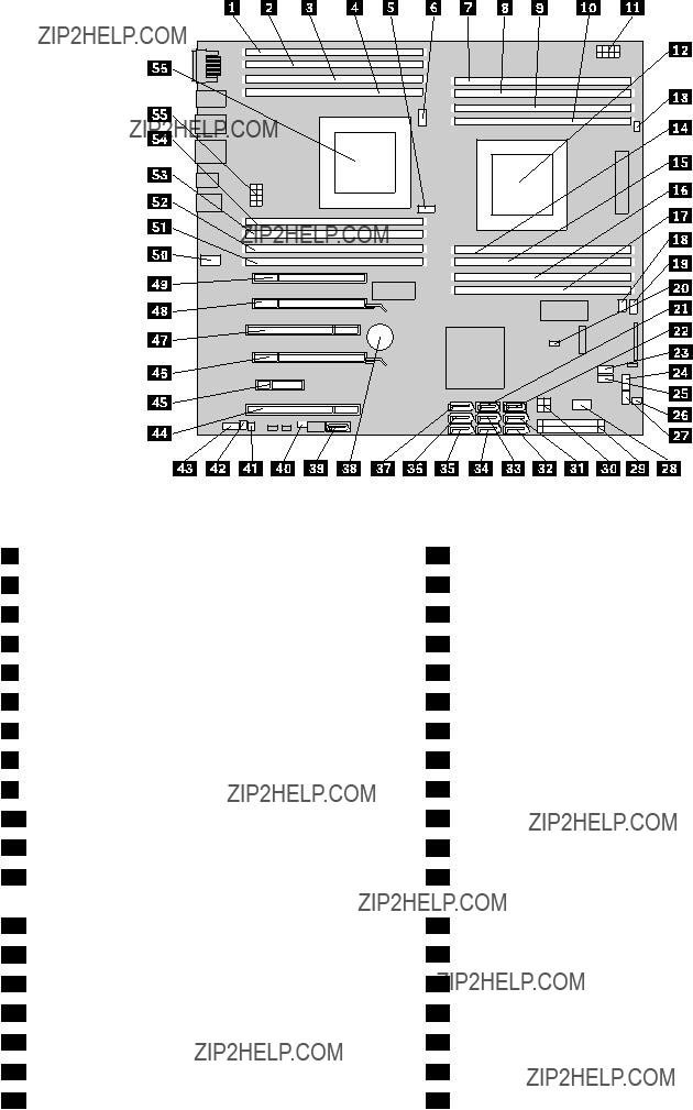
Figure 4. System board part locations
1Microprocessor 2 memory slot 3 (DIMM3)
2Microprocessor 2 memory slot 7 (DIMM7)
3Microprocessor 2 memory slot 4 (DIMM4)
4Microprocessor 2 memory slot 8 (DIMM8)
5Microprocessor 2 memory cooler connector
6Microprocessor 2 fan connector
7Microprocessor 1 memory slot 1 (DIMM1)
8Microprocessor 1 memory slot 5 (DIMM5)
9Microprocessor 1 memory slot 2 (DIMM2)
10Microprocessor 1 memory slot 6 (DIMM6)
11Microprocessor 1 12 volt power connector
12Microprocessor 1
13Microprocessor 1 fan connector
14Microprocessor 1 memory slot 8 (DIMM8)
15Microprocessor 1 memory slot 4 (DIMM4)
16Microprocessor 1 memory slot 7 (DIMM7)
17Microprocessor 1 memory slot 3 (DIMM3)
18Front fan connector
19Microprocessor 1 memory cooler connector
29ATX power connector
3012 volt power connector
31SATA port 2
32SATA port 1
33Hard disk drive connector 5
34Hard disk drive connector 4
35Hard disk drive connector 1
36Hard disk drive connector 2
37Hard disk drive connector 3
38Battery
39eSATA connector
40Cover presence switch connector (Intrusion switch connector)
41Thermal sensor
42Internal speaker connector
43Front audio connector
44PCI card slot
45PCI Express x4 card slot
46PCI Express x16 card slot
47PCI card slot
Chapter 9. Locations 59

20Clear CMOS (Complementary Metal Oxide Semiconductor) / Recovery jumper
21SATA port 4
22SATA port 3
23Media card reader connector
24Front panel connector
25Front USB connector
26Hard disk drive enablement module connector
27Auxiliary LED connector
28Internal USB 2.0 port
48PCI Express x16 card slot
49PCI Express x4 card slot (x16 mechanical)
50Rear fan connector
51Microprocessor 2 memory slot 1 (DIMM1)
52Microprocessor 2 memory slot 5 (DIMM5)
53Microprocessor 2 memory slot 2 (DIMM2)
54Microprocessor 2 memory slot 6 (DIMM6)
55Microprocessor 2 12 volt power connector
56Microprocessor 2
60 ThinkStation Hardware Maintenance Manual

Locating internal drives
Internal drives are devices that your computer uses to read and store data. You can add drives to your computer to increase storage capacity and enable your computer to read other types of media. Internal drives are installed in bays. In this manual, the bays are referred to as bay 1, bay 2, and so on.
When installing or replacing an internal drive, it is important to note the type and size of the drive that you can install or replace in each bay and correctly connect the cables to the drive installed. Refer to the appropriate section in ???Installing or replacing hardware??? on page 63 for instructions on how to install or replace internal drives for your computer.
Figure 5 ???Drive bay locations??? on page 61 shows the locations of the drive bays.
Figure 5. Drive bay locations
1
2
3
Optical drive bay 1 to 3 (with optical drives installed on some models) Card reader drive bay
Hard disk drive bay 1 to 5 (with hard disk drives installed)
Chapter 9. Locations 61
62 ThinkStation Hardware Maintenance Manual

Chapter 10. Replacing FRUs
This chapter provides information about the FRU replacement instructions.
Important
Be sure to read and understand Chapter 2 ???Safety information??? on page 3 before replacing any FRU. These precautions and guidelines will help you work safely.
Note: FRU replacements are to be done only by trained service technicians.
Installing or replacing hardware
This section provides instructions on how to install or replace hardware for your computer. You can expand the capabilities of your computer and maintain your computer by installing or replacing hardware.
Attention: Do not open your computer or attempt any repair before reading and understanding the ???Important Safety Information??? on page 1.
Notes:
1.Use only computer parts provided by Lenovo.
2.When installing or replacing an option, use the appropriate instructions in this section along with the instructions that come with the option.
Handling
Do not open the
When you handle parts and other computer components, take these precautions to avoid
???Limit your movement. Movement can cause static electricity to build up around you.
???Always handle parts and other computer components carefully. Handle PCI cards, memory modules, system boards, and microprocessors by the edges. Never touch any exposed circuitry.
???Prevent others from touching the parts and other computer components.
???Before you replace a new part, touch the
???When possible, remove the new part from the
???Do not place the part on the computer cover or other metal surface.
Installing external options
You can connect external options to your computer, such as external speakers, a printer, or a scanner. For some external options, you must install additional software in addition to making the physical connection. When installing an external option, see ???Locating connectors, controls, and indicators on the front of your computer??? on page 55 and ???Locating connectors on the rear of your computer??? on page 56 to identify the

required connector. Then, use the instructions that come with the option to help you make the connection and install any software or device drivers that are required for the option.
Removing the computer cover
Attention: Do not open your computer or attempt any repair before reading and understanding the ???Important Safety Information??? on page 1.
This section provides instructions on how to remove the computer cover.
CAUTION:
Turn off the computer and wait three to five minutes to let the computer cool before removing the computer cover.
To remove the computer cover, do the following:
1.Remove any media from the drives and turn off all attached devices and the computer.
2.Disconnect all power cords from electrical outlets.
3.Disconnect the power cords, Input/Output cables, and any other cables that are connected to the computer. See ???Locating connectors, controls, and indicators on the front of your computer??? on page 55 and ???Locating connectors on the rear of your computer??? on page 56.
4.Remove any locking device that secures the computer cover, such as a padlock or an integrated cable lock.
64 ThinkStation Hardware Maintenance Manual
5. Disengage the cover latch 1 and remove the cover. Place the cover on a flat surface.
Figure 6. Removing the computer cover
Removing and reinstalling the front bezel
Attention: Do not open your computer or attempt any repair before reading and understanding the ???Important Safety Information??? on page 1.
This section provides instructions on how to remove and reinstall the front bezel.
To remove and reinstall the front bezel, do the following:
1.Turn off the computer and disconnect all power cords from electrical outlets.
2.Remove the computer cover. See ???Removing the computer cover??? on page 64.
Chapter 10. Replacing FRUs 65

3.Remove the front bezel by releasing the two plastic tabs on the left side and pivoting the front bezel outward.
Figure 7. Removing the front bezel
4.To reinstall the front bezel, align the three plastic tabs on the right side of the front bezel with the corresponding holes in the chassis, and then pivot the front bezel inwards until the two plastic tabs snaps into position on the left side.
What to do next:
???To work with another piece of hardware, go to the appropriate section.
???To complete the installation or replacement, go to ???Completing the parts replacement??? on page 104.
Installing or replacing a PCI card
Attention: Do not open your computer or attempt any repair before reading and understanding the ???Important Safety Information??? on page 1.
This section provides instructions on how to install or replace a PCI card. Your computer has two standard PCI card slots, two PCI Express x4 card slots, and two PCI Express x16 graphics card slots.
To install or replace a PCI card, do the following:
1.Turn off the computer and disconnect all power cords from electrical outlets.
2.Remove the computer cover. See ???Removing the computer cover??? on page 64.
3.Open the PCI card retainer by lifting the retainer and then pivoting it out.
66 ThinkStation Hardware Maintenance Manual
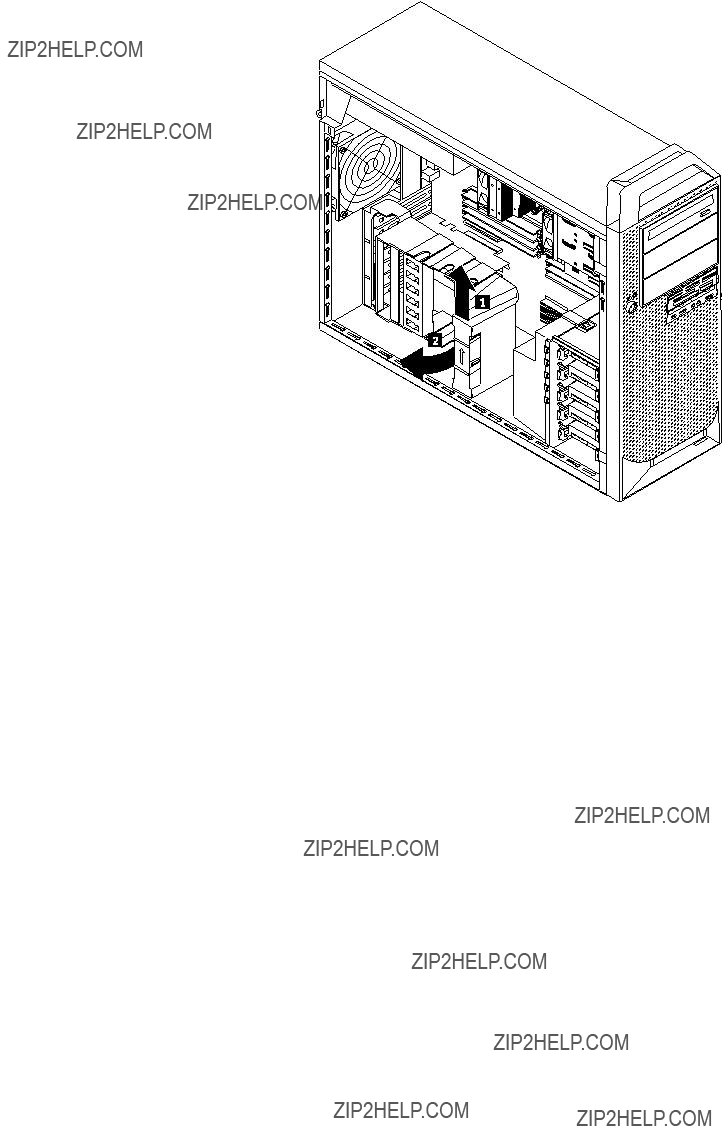
Figure 8. Opening the PCI card retainer
4.Depending on whether you are installing or replacing a PCI card, do one of the following:
???If you are installing a PCI card, remove the appropriate metal card slot cover.
???If you are replacing an old PCI card, grasp the old card that is currently installed and gently pull it out of the card slot.
Chapter 10. Replacing FRUs 67
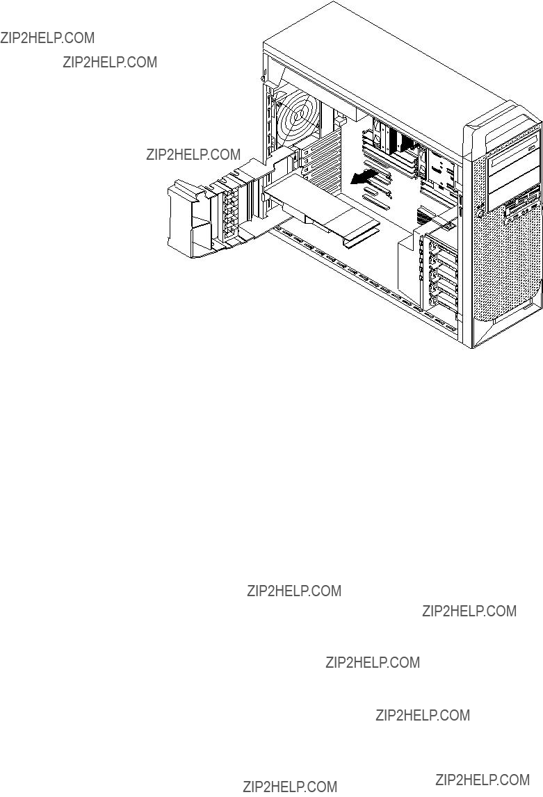
Figure 9. Removing a PCI card
Notes:
a.The card fits tightly into the card slot. If necessary, alternate moving each side of the card a small amount until it is removed from the card slot.
68 ThinkStation Hardware Maintenance Manual
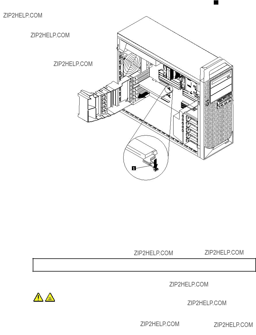
b.If the card is held in place by a retaining latch, press the card retaining latch 1 as shown to disengage the latch. Grasp the card and gently pull it out of the card slot.
5.Remove the new PCI card from its
6.Install the new card into the appropriate card slot on the system board. See ???Locating parts on the system board??? on page 58.
7.Pivot the PCI card latch to the closed position to secure the PCI card.
What to do next:
???To work with another piece of hardware, go to the appropriate section.
???To complete the installation or replacement, go to ???Completing the parts replacement??? on page 104.
Installing or replacing a memory module
Attention: Do not open your computer or attempt any repair before reading and understanding the ???Important Safety Information??? on page 1.
This section provides instructions on how to install or replace a memory module.
CAUTION:
Chapter 10. Replacing FRUs 69

Turn off the computer and wait three to five minutes to let the computer cool before installing or replacing a memory module.
Your computer has 16 slots for installing or replacing DDR3 ECC UDIMMs or DDR3 ECC RDIMMs. When installing or replacing a memory module, use the following guidelines:
???Use either DDR3 ECC UDIMMs or DDR3 ECC RDIMMs for your computer. Do not install both the UDIMMs and RDIMMs into the same computer.
???Use 2 GB, 4 GB, or 8 GB UDIMMs in any combination up to a maximum of 128 GB.
???Use 2 GB, 4 GB, 8 GB, 16 GB, or 32 GB DDR3 RDIMMs in any combination up to a maximum of 512 GB.
???Always install DIMMs in the numerical order printed on the system board (DIMM1, DIMM2, DIMM3, and so on). Install memory modules into the blue color memory slots first. See ???Locating parts on the system board??? on page 58.
???If your computer has only one microprocessor installed, be sure to install memory modules only in the memory slots adjacent to that microprocessor.
???If your computer has two microprocessors installed, install equal numbers of memory modules in both sets of microprocessor DIMM slots for maximum performance.
To install or replace a memory module, do the following:
1.Turn off the computer and disconnect all power cords from electrical outlets.
2.Remove the computer cover. See ???Removing the computer cover??? on page 64.
3.Lay the computer on its side for easier access to the system board.
4.Locate the memory slots. See ???Locating parts on the system board??? on page 58.
5.Remove any parts that might prevent your access to the memory slots. Depending on your computer model, you might need to remove the PCI Express x16 graphics card for easier access to the memory slots. See ???Installing or replacing a PCI card??? on page 66.
6.For some computer models, you might need to remove the memory fan duct to get access to the memory slots. To remove the memory fan duct, disconnect the memory fan cable from the system board. See ???Locating parts on the system board??? on page 58.
7.Pull the fan duct tab outward and pivot the fan duct, and then disengage the rear of the fan duct.
Note: Not all computer models have the memory fan duct.
Figure 10. Removing the memory fan duct
8. Depending on whether you are installing or replacing a memory module, do one of the following:
70 ThinkStation Hardware Maintenance Manual
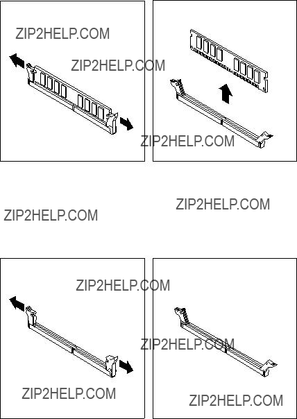
???If you are replacing an old memory module, open the retaining clips and gently pull the memory module out of the memory slot.
Figure 11. Removing a memory module
???If you are installing a memory module, open the retaining clips of the memory slot into which you want to install the memory module.
Figure 12. Opening the retaining clips
Chapter 10. Replacing FRUs 71
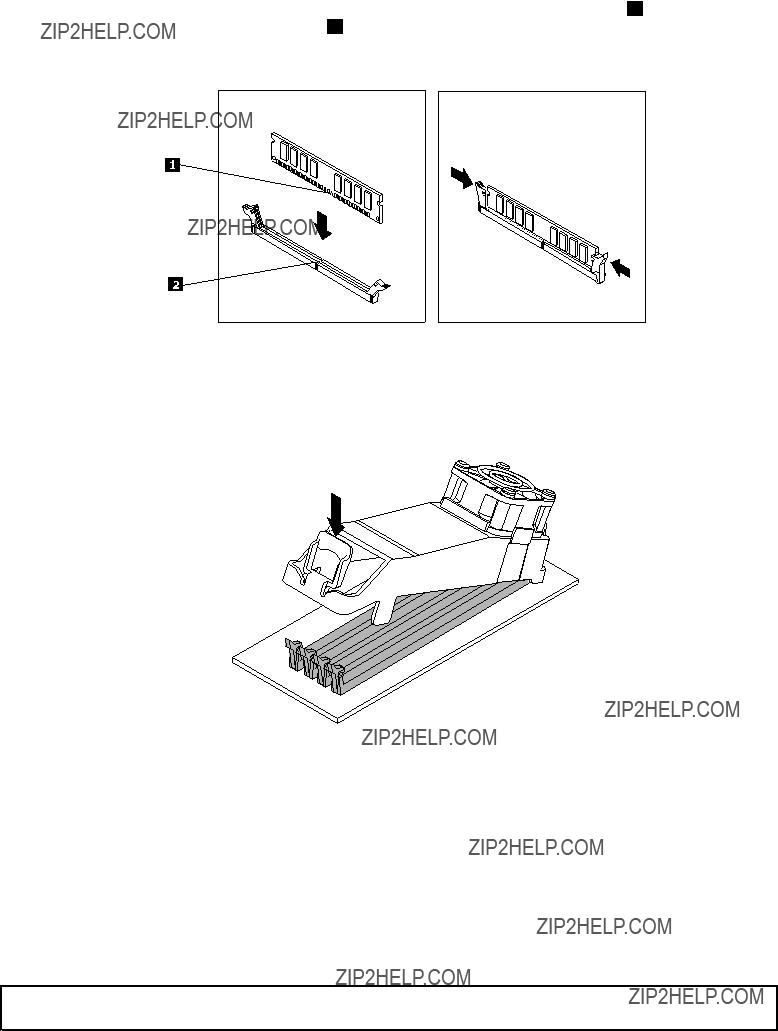
9.Position the new memory module over the memory slot. Make sure that the notch 1 on the memory module aligns correctly with the slot key 2 on the system board. Push the memory module straight down into the slot until the retaining clips close.
Figure 13. Installing a memory module
10.To install the memory fan duct, secure the rear of the fan duct with the retaining clips of the memory slots, and then pivot the fan duct downward until the fan duct snaps into position.
Figure 14. Installing the memory fan duct
11.Reconnect the memory fan cable to the system board. See ???Locating parts on the system board??? on page 58.
12.Reinstall the PCI Express x16 graphics card if you have removed it.
What to do next:
???To work with another piece of hardware, go to the appropriate section.
???To complete the installation or replacement, go to ???Completing the parts replacement??? on page 104.
Installing or replacing the optical drive
Attention: Do not open your computer or attempt any repair before reading and understanding the ???Important Safety Information??? on page 1.
72 ThinkStation Hardware Maintenance Manual

This section provides instructions on how to install or replace the optical drive.
To install or replace an optical drive, do the following:
1.Turn off the computer and disconnect all power cords from electrical outlets.
2.Remove the computer cover. See ???Removing the computer cover??? on page 64.
3.Remove the front bezel. See ???Removing and reinstalling the front bezel??? on page 65.
4.Locate the optical drive. See ???Locating major FRUs and CRUs??? on page 56.
5.Depending on whether you are installing or replacing an optical drive, do one of the following:
???If you are installing a secondary optical drive, remove the plastic panel in the front bezel for the drive bay you want to use. If there is a metal static shield installed in the drive bay, remove the metal static shield.
???If you are replacing an optical drive, disconnect the signal cable and the power cable from the rear of the optical drive, press the drive latch 1 , and then slide the optical drive out of the front of the computer.
Figure 15. Removing the optical drive
Chapter 10. Replacing FRUs 73

6. Install the optical drive retainer on the side of the new optical drive.
Figure 16. Installing the optical drive retainer
7.Slide the new optical drive into the drive bay from the front of the computer until the optical drive snaps into position.
Figure 17. Installing the optical drive
74 ThinkStation Hardware Maintenance Manual
8. Connect the signal cable and the power cable to the new optical drive.
Figure 18. Connecting the optical drive
9. Reinstall the front bezel. See ???Removing and reinstalling the front bezel??? on page 65.
What to do next:
???To work with another piece of hardware, go to the appropriate section.
???To complete the installation or replacement, go to ???Completing the parts replacement??? on page 104.
Replacing the card reader
Attention: Do not open your computer or attempt any repair before reading and understanding the ???Important Safety Information??? on page 1.
This section provides instructions on how to install or replace the card reader.
To replace the card reader, do the following:
1.Remove all media from the drives and turn off all attached devices and the computer. Then, disconnect all power cords from electrical outlets and disconnect all cables that are connected to the computer.
2.Remove the computer cover. See ???Removing the computer cover??? on page 64.
3.Remove the front bezel. See ???Removing and reinstalling the front bezel??? on page 65.
4.Locate the card reader. See ???Locating major FRUs and CRUs??? on page 56.
5.Disconnect the card reader cable from the system board. See ???Locating parts on the system board??? on page 58.
Chapter 10. Replacing FRUs 75

6. Press the blue retaining clip 1 to remove the card reader out of the chassis.
Figure 19. Removing the card reader
7. Install the card reader retainer on the side of the new card reader.
Figure 20. Installing the card reader retainer
76 ThinkStation Hardware Maintenance Manual

8. Slide the card reader with retainer into the card reader drive bay until it snaps into position.
Figure 21. Installing the card reader
9.Reconnect the card reader cable to the system board. See ???Locating parts on the system board??? on page 58.
10.Reinstall the front bezel. See ???Removing and reinstalling the front bezel??? on page 65.
What to do next:
???To work with another piece of hardware, go to the appropriate section.
???To complete the installation or replacement, go to ???Completing the parts replacement??? on page 104.
Replacing the battery
Attention: Do not open your computer or attempt any repair before reading and understanding the ???Important Safety Information??? on page 1.
Your computer has a special type of memory that maintains the date, time, and settings for
The battery normally requires no charging or maintenance throughout its life; however, no battery lasts forever. If the battery fails, the date, time, and configuration information (including passwords) are lost. An error message is displayed when you turn on the computer.
Chapter 10. Replacing FRUs 77

Refer to the ???Lithium battery notice??? in the ThinkStation Safety and Warranty Guide for information about replacing and disposing of the battery.
To replace the battery, do the following:
1.Turn off the computer and disconnect all power cords from electrical outlets.
2.Remove the computer cover. See ???Removing the computer cover??? on page 64.
3.Locate the battery. See ???Locating parts on the system board??? on page 58.
4.Remove the old battery.
Figure 22. Removing the old battery
5. Install a new battery.
Figure 23. Installing a new battery
6.Reinstall the computer cover and connect the cables. See ???Completing the parts replacement??? on page 104.
Note: When the computer is turned on for the first time after replacing the battery, an error message might be displayed. This is normal after replacing the battery.
7.Turn on the computer and all attached devices.
8.Use the Setup Utility program to set the date, time, and any passwords. See Chapter 6 ???Using the Setup Utility program??? on page 37.
What to do next:
???To work with another piece of hardware, go to the appropriate section.
???To complete the installation or replacement, go to ???Completing the parts replacement??? on page 104.
Replacing the heat sink and fan assembly
Attention: Do not open your computer or attempt any repair before reading and understanding the ???Important Safety Information??? on page 1.
This section provides instructions on how to replace the heat sink and fan assembly.
78 ThinkStation Hardware Maintenance Manual

CAUTION:
The heat sink and fan assembly might be very hot. Turn off the computer and wait three to five minutes to let the computer cool before removing the computer cover.
To replace the heat sink and fan assembly, do the following:
1.Turn off the computer and disconnect all power cords from electrical outlets.
2.Remove the computer cover. See ???Removing the computer cover??? on page 64.
3.Lay the computer on its side for easier access to the system board.
4.Locate the heat sink and fan assembly you want to replace. Your computer have two heat sink and fan assemblies. See ???Locating parts on the system board??? on page 58.
5.Disconnect the heat sink and fan assembly cable from the microprocessor fan connector on the system board. See ???Locating parts on the system board??? on page 58.
6.Follow this sequence to remove the four screws that secure each heat sink and fan assembly to the system board:
a.Partially remove screw 1 , then fully remove screw 2 , and then fully remove screw 1 .
b.Partially remove screw 3 , then fully remove screw 4 , and then fully remove screw 3 .
Note: Carefully remove the four screws from the system board to avoid any possible damage to the system board. The four screws cannot be removed from the heat sink and fan assembly.
Figure 24. Removing the heat sink and fan assembly
7.Lift the failing heat sink and fan assembly off the system board.
Notes:
a.You might have to gently twist the heat sink and fan assembly to free it from the microprocessor.
b.Do not touch the thermal grease while handling the heat sink and fan assembly.
8.Position the two new heat sink and fan assemblies in a way that the fans are toward the rear of the computer. Align the four screws on each heat sink and fan assembly with the holes on the system board.
Chapter 10. Replacing FRUs 79
9.Follow the following sequence to install the four screws to secure each new heat sink and fan assembly. Do not
a.Partially tighten screw 1 , then fully tighten screw 2 , and then fully tighten screw 1 .
b.Partially tighten screw 3 , then fully tighten screw 4 , and then fully tighten screw 3 .
10.Connect the heat sink and fan assembly cables to the microprocessor fan connectors on the system board. See ???Locating parts on the system board??? on page 58.
What to do next:
???To work with another piece of hardware, go to the appropriate section.
???To complete the installation or replacement, go to ???Completing the parts replacement??? on page 104.
Replacing the hard disk drive fan assembly
Attention: Do not open your computer or attempt any repair before reading and understanding the ???Important Safety Information??? on page 1.
This section provides instructions on how to replace the hard disk drive fan assembly.
To replace the hard disk drive fan assembly, do the following:
1.Turn off the computer and disconnect all power cords from electrical outlets.
2.Remove the computer cover. See ???Removing the computer cover??? on page 64.
3.Disconnect the hard disk drive fan assembly cable from the system board. See ???Locating parts on the system board??? on page 58.
4.Remove any parts that might prevent your access to the hard disk drive fan assembly. Depending on your computer model, you might need to remove the PCI Express x16 graphics card for easier access to the hard disk drive fan assembly. See ???Installing or replacing a PCI card??? on page 66.
80 ThinkStation Hardware Maintenance Manual

5. Press the tab, and then pivot the hard disk drive fan outward to remove it from the chassis.
Figure 25. Removing the hard disk drive fan assembly
6.Position the hard disk drive fan, and then pivot the fan to insert the tab into the chassis.
7.Reconnect the hard disk drive fan cable to the system board.
What to do next:
???To work with another piece of hardware, go to the appropriate section.
???To complete the installation or replacement, go to ???Completing the parts replacement??? on page 104.
Replacing the rear fan assembly
Attention: Do not open your computer or attempt any repair before reading and understanding the ???Important Safety Information??? on page 1.
This section provides instructions on how to replace the rear fan assembly.
To replace the rear fan assembly, do the following:
1.Turn off the computer and disconnect all power cords from electrical outlets.
2.Remove the computer cover. See ???Removing the computer cover??? on page 64.
3.Locate the rear fan assembly. See ???Locating major FRUs and CRUs??? on page 56.
4.Disconnect the rear fan assembly cable from the system fan connector on the system board. See ???Locating parts on the system board??? on page 58.
Chapter 10. Replacing FRUs 81

5.The rear fan assembly is attached to the chassis by four rubber mounts. Remove the rear fan assembly by breaking or cutting the rubber mounts and gently pulling the rear fan assembly out of the chassis.
Note: The new rear fan assembly will have four new rubber mounts attached.
Figure 26. Removing the rear fan assembly
6.Install the new rear fan assembly by aligning the new rubber mounts with the corresponding holes in the chassis and push the rubber mounts through the holes. Pull on the tips of the rubber mounts until the rear fan assembly is secured in place.
82 ThinkStation Hardware Maintenance Manual
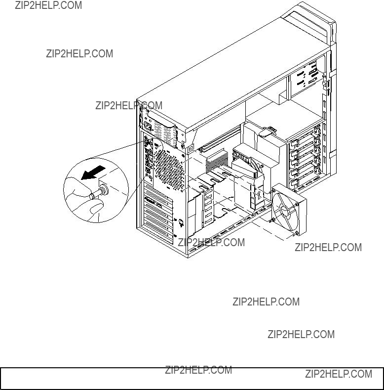
Figure 27. Installing the rear fan assembly
7. Connect the rear fan assembly cable to the system fan connector on the system board.
What to do next:
???To work with another piece of hardware, go to the appropriate section.
???To complete the installation or replacement, go to ???Completing the parts replacement??? on page 104.
Installing or replacing a hard disk drive
Attention: Do not open your computer or attempt any repair before reading and understanding the ???Important Safety Information??? on page 1.
This section provides instructions on how to install or replace a hard disk drive.
Notes: If you are installing additional hard disk drives, ensure that your computer is properly configured to support them.
???If installing five SATA hard disk drives, ensure that the SATA hard disk drive enablement module (one to five hard disk drives) is installed.
???If installing SAS hard disk drives, ensure that the SAS hard disk drive enablement module or the LSI MegaRAID SAS adapter is installed.
To install or replace a hard disk drive, do the following:
1. Turn off the computer and disconnect all power cords from electrical outlets.
Chapter 10. Replacing FRUs 83
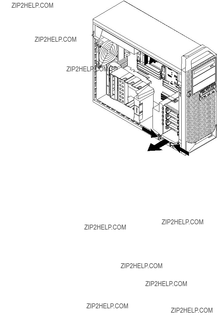
2.Remove the computer cover. See ???Removing the computer cover??? on page 64.
3.Locate the hard disk drive. See ???Locating internal drives??? on page 61.
4.Disconnect the signal cable and the power cable from the hard disk drive.
5.Pull the bracket handle out to remove the hard disk drive from the chassis.
Figure 28. Removing the hard disk drive
6. Flex the sides of the bracket to remove the hard disk drive from the bracket.
84 ThinkStation Hardware Maintenance Manual
7.To install a new hard disk drive into the bracket, flex the bracket and align pin 1 , pin 2 , pin 3 , and pin 4 on the bracket with the corresponding holes in the hard disk drive. Do not touch the circuit board 5 on the bottom of the hard disk drive.
Figure 29. Installing the hard disk drive into the bracket
Note: If you are replacing or installing a
Figure 30. Installing
8. Slide the new hard disk drive into the drive cage until it snaps into position.
Chapter 10. Replacing FRUs 85
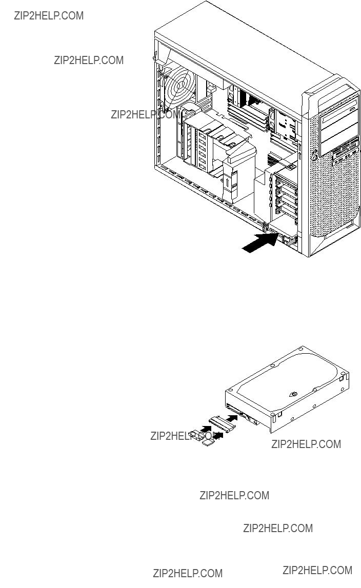
Figure 31. Installing the hard disk drive
9.Connect the signal cable and the power cable to the new hard disk drive.
Note: If you are installing SAS hard disk drives, you must connect the signal cables and power cables to the
Figure 32. Connecting SAS cables to
86 ThinkStation Hardware Maintenance Manual

What to do next:
???To work with another piece of hardware, go to the appropriate section.
???To complete the installation or replacement, go to ???Completing the parts replacement??? on page 104.
Installing or replacing a hard disk drive enablement module
Attention: Do not open your computer or attempt any repair before reading and understanding the ???Important Safety Information??? on page 1.
This section provides instructions on how to install or replace a hard disk drive enablement module.
To install or replace a hard disk drive enablement module, do the following:
1.Turn off the computer and disconnect all power cords from electrical outlets.
2.Remove the computer cover. See ???Removing the computer cover??? on page 64.
3.Lift to open the PCI card retainer. See Figure 8 ???Opening the PCI card retainer??? on page 67.
4.Remove the hard disk drive fan assembly. See ???Replacing the hard disk drive fan assembly??? on page 80.
5.Locate the hard disk drive enablement module. See ???Locating parts on the system board??? on page 58.
6.If you are replacing the hard disk drive enablement module, press the plastic tabs together and then lift the hard disk drive enablement module upward to remove it from the system board.
Figure 33. Removing the hard disk drive enablement module
Chapter 10. Replacing FRUs 87

7.To install a new hard disk drive enablement module, align the hole in the hard disk drive enablement module with the plastic standoff on the system board, and then position the hard disk drive module over the corresponding connector on the system board.
Figure 34. Installing a new hard disk drive enablement module
8.Reinstall the hard disk drive fan assembly and close the PCI card retainer. See ???Replacing the hard disk drive fan assembly??? on page 80.
What to do next:
???To work with another piece of hardware, go to the appropriate section.
???To complete the installation or replacement, go to ???Completing the parts replacement??? on page 104.
Replacing the front audio and USB assembly
Attention: Do not open your computer or attempt any repair before reading and understanding the ???Important Safety Information??? on page 1.
This section provides instructions on how to replace the front audio and USB assembly.
To replace the front audio and USB assembly, do the following:
1.Turn off the computer and disconnect all power cords from electrical outlets.
2.Remove the computer cover. See ???Removing the computer cover??? on page 64.
3.Remove the front bezel. See ???Removing and reinstalling the front bezel??? on page 65.
4.Locate the front audio and USB assembly. See ???Locating major FRUs and CRUs??? on page 56.
88 ThinkStation Hardware Maintenance Manual

5.Disconnect the front audio and USB assembly cables from the system board. See ???Locating parts on the system board??? on page 58.
Note: Make sure you note the locations of the cables when you disconnect the cables from the system board.
6.Remove the two screws that secure the front audio and USB assembly bracket, and then remove the bracket from the chassis.
Figure 35. Removing the two screws that secure the front audio and USB assembly to the chassis
7.Position the front audio and USB assembly bracket into the chassis, and then align the two screw holes in the bracket with the corresponding holes in the chassis. Install the two screws to secure the front audio and USB bracket to the chassis.
8.Reconnect the front audio and USB assembly cables to the front audio connector and the front USB connector on the system board. See ???Locating parts on the system board??? on page 58.
What to do next:
???To work with another piece of hardware, go to the appropriate section.
???To complete the installation or replacement, go to ???Completing the parts replacement??? on page 104.
Replacing the internal speaker
Attention: Do not open your computer or attempt any repair before reading and understanding the ???Important Safety Information??? on page 1.
This section provides instructions on how to replace the internal speaker.
Chapter 10. Replacing FRUs 89

Note: The internal speaker is only available on some models.
To replace the internal speaker, do the following:
1.Turn off the computer and disconnect all power cords from electrical outlets.
2.Remove the computer cover. See ???Removing the computer cover??? on page 64.
3.Locate the internal speaker connector and disconnect the internal speaker cable form the system board. See ???Locating parts on the system board??? on page 58.
4.Press the tab 3 inward and slide the internal speaker 1 upward to completely remove it from the chassis.
Figure 36. Removing the internal speaker
5.Position the new internal speaker to insert the two tabs 2 into the corresponding holes in the chassis, and then push downward the internal speaker until it is secured in place.
6.Connect the internal speaker cable to the system board. See ???Locating parts on the system board??? on page 58.
What to do next:
???To work with another piece of hardware, go to the appropriate section.
???To complete the installation or replacement, go to ???Completing the parts replacement??? on page 104.
Installing or replacing the microprocessor
This topic provides instructions on how to install or replace the microprocessor.
90 ThinkStation Hardware Maintenance Manual

Installing the second microprocessor
Attention: Do not open your computer or attempt any repair before reading and understanding the ???Important Safety Information??? on page 1.
This topic provides instructions on how to install the second microprocessor.
Depending on the model, your computer might come with one or two microprocessors. For computer models with one microprocessor, the microprocessor is installed in the microprocessor socket 1 and the microprocessor socket 2 is protected by a plastic socket cover. You can purchase a microprocessor option kit from Lenovo and install the second microprocessor to expand system capabilities.
CAUTION:
 The heat sink and microprocessor might be very hot. Turn off the computer and wait three to five minutes to let the computer cool before removing the computer cover.
Notes:
???Ensure that you install the correct type of microprocessor option your computer supports. When two microprocessors are installed, both must be identical.
???A second heat sink and fan assembly is also required. Ensure that you have this assembly available before starting the installation.
???Use any documentation that comes with the microprocessor option kit and follow those instructions in addition to the instructions in this topic.
???Your microprocessor, socket, and socket cover might look slightly different from the illustrations in this topic.
To install the second microprocessor, do the following:
1.Remove all media from the drives and turn off all attached devices and the computer. Then, disconnect all power cords from electrical outlets and disconnect all cables that are connected to the computer.
2.Remove the computer cover. See ???Removing the computer cover??? on page 64.
3.Place the computer on its side to gain easier access to the system board.
4.Locate the microprocessor socket 2 on the system board. See ???Locating parts on the system board??? on page 58.
Chapter 10. Replacing FRUs 91
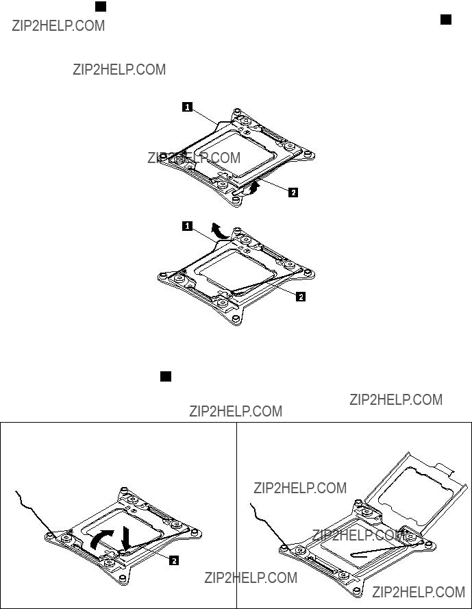
5.Open the small handle 2 by gently pressing down the small handle, and then pulling the small handle a little bit outward to release it from the secured position. Then, open the other small handle 1 by following the same instructions. Ensure that the small handles are in the fully open position.
Note: There are two marks on the microprocessor retainer. You need to open the small handle marked with 

 first, and then you can open the other small handle marked with

 .
.
Figure 37. Opening the handles
6.Gently press down the small handle 2 to open the microprocessor retainer. Pivot the retainer upward until it is in the fully open position.
Figure 38. Opening the microprocessor retainer
7.Touch only the edges of the microprocessor and carefully lift it straight up and out of the microprocessor socket. Place the old microprocessor on a
Notes:
??? Do not touch the gold contacts on the bottom of the microprocessor.
92 ThinkStation Hardware Maintenance Manual

???Do not drop anything onto the microprocessor socket while it is exposed. The socket pins must be kept as clean as possible.
Figure 39. Removing the microprocessor
8.Touch the
9.Remove the new microprocessor from the protective cover that protects the gold contacts on the bottom of the new microprocessor. Do not touch the pins on the microprocessor socket or the gold contacts on the bottom of the new microprocessor.
Figure 40. Do not touch the pins
Chapter 10. Replacing FRUs 93

10.Note the orientation of the new microprocessor. Hold the new microprocessor by its edges and align the notches 1 on it with the tabs 2 in the microprocessor socket. Then, carefully lower the new microprocessor straight down into the microprocessor socket.
Note: The small triangle 3 on one corner of the new microprocessor is the microprocessor orientation indicator. The new microprocessor is in the correct orientation when this indicator faces the beveled corner 4 of the microprocessor socket.
Figure 41. Installing the microprocessor
11. Pivot the microprocessor retainer downward to close the retainer.
Figure 42. Closing the microprocessor retainer
94 ThinkStation Hardware Maintenance Manual
12.Gently press down the small handle 1 , and then push the handle inward to secure it. Then gently press down the small handle 2 and push the handle inward to lock the microprocessor retainer into position and secure the new microprocessor in the socket.
Note: There are two marks on the microprocessor retainer. Ensure that you close the small handle marked with 

 first, and then close the small handle marked with

 . Always follow the correct sequence when you close the small handles.
Figure 43. Securing the microprocessor in the socket
13. Install the heat sink and fan assembly. See ???Replacing the heat sink and fan assembly??? on page 78.
What to do next:
???To work with another piece of hardware, go to the appropriate section.
???To complete the replacement, go to ???Completing the parts replacement??? on page 104.
Replacing a microprocessor
Attention: Do not open your computer or attempt any repair before reading and understanding the ???Important Safety Information??? on page 1.
This section provides instructions on how to replace a microprocessor.
Depending on the model, your computer might come with one or two microprocessors. For computer models with one microprocessor, the microprocessor is installed in the microprocessor socket 1 and the microprocessor socket 2 is protected by a plastic socket cover. You can purchase a microprocessor option kit from Lenovo and install the second microprocessor to expand computer capabilities.
CAUTION:
 The heat sink and microprocessor might be very hot. Turn off the computer and wait three to five minutes to let the computer cool before removing the computer cover.
Notes:
???Ensure that you install the correct type of microprocessor option your computer supports. When two microprocessors are installed, both must be identical.
Chapter 10. Replacing FRUs 95
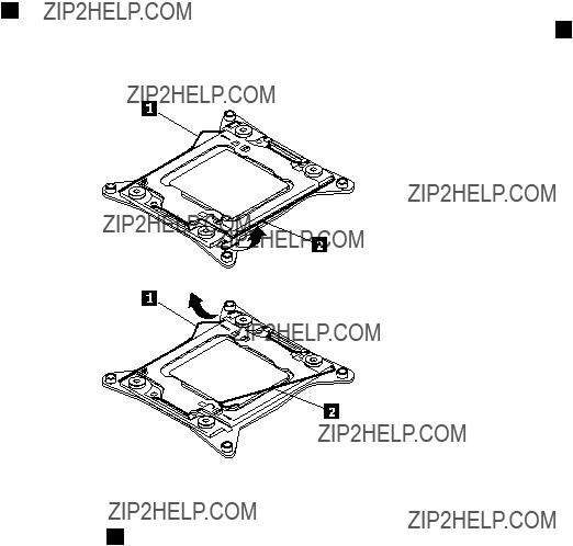
???Use any documentation that comes with the microprocessor option kit and follow those instructions in addition to the instructions in this topic.
???Your microprocessor, socket, and socket cover might look slightly different from the illustrations in this topic.
To replace a microprocessor, do the following:
1.Remove all media from the drives and turn off all attached devices and the computer. Then, disconnect all power cords from electrical outlets and disconnect all cables that are connected to the computer.
2.Remove the computer cover. See ???Removing the computer cover??? on page 64.
3.Place the computer on its side to gain easier access to the system board.
4.Remove the heat sink and fan assembly. See ???Replacing the heat sink and fan assembly??? on page 78.
5.Locate the correct microprocessor socket on the system board . See ???Replacing the system board??? on page 99.
6.Open the small handle 2 by gently pressing down the small handle, and then pulling the small handle a little bit outward to release it from the secured position. Then, open the other small handle 1 by following the same instructions. Ensure that the small handles are in the fully open position.
Figure 44. Opening the handles
7.Gently press down the small handle 2 to open the microprocessor retainer. Pivot the retainer upward until it is in the fully open position.
96 ThinkStation Hardware Maintenance Manual

Figure 45. Opening the microprocessor retainer
8.Touch only the edges of the microprocessor and carefully lift it straight up and out of the microprocessor socket. Place the old microprocessor on a
Notes:
???Do not touch the gold contacts on the bottom of the microprocessor.
???Do not drop anything onto the microprocessor socket while it is exposed. The socket pins must be kept as clean as possible.
Figure 46. Removing the microprocessor
9.Touch the
Chapter 10. Replacing FRUs 97

10.Remove the new microprocessor from the protective cover that protects the gold contacts on the bottom of the new microprocessor. Do not touch the pins on the microprocessor socket or the gold contacts on the bottom of the new microprocessor.
Figure 47. Do not touch the pins
11.Note the orientation of the new microprocessor. Hold the new microprocessor by its edges and align the notches 1 on it with the tabs 2 in the microprocessor socket. Then, carefully lower the new microprocessor straight down into the microprocessor socket.
Note: The small triangle 3 on one corner of the new microprocessor is the microprocessor orientation indicator. The new microprocessor is in the correct orientation when this indicator faces the beveled corner 4 of the microprocessor socket.
Figure 48. Installing the microprocessor
98 ThinkStation Hardware Maintenance Manual

12. Pivot the microprocessor retainer downward to close the retainer.
Figure 49. Closing the microprocessor retainer
13.Gently press down the small handle 1 , and then push the handle inward to secure it. Then gently press down the small handle 2 and push the handle inward to lock the microprocessor retainer into position and secure the new microprocessor in the socket.
Note: There are two marks on the microprocessor retainer. Ensure that you close the small handle marked with 

 first, and then close the small handle marked with

 . Always follow the correct sequence when you close the small handles.
Figure 50. Securing the microprocessor in the socket
14.Reinstall the heat sink and fan assembly. See ???Replacing the heat sink and fan assembly??? on page 78.
15.If you are instructed to return the old microprocessor, follow all packaging instructions and use any packaging materials that are supplied to you for shipping.
16.To complete the replacement, go to ???Completing the parts replacement??? on page 104.
Replacing the system board
Attention: Do not open your computer or attempt any repair before reading and understanding the ???Important Safety Information??? on page 1.
This section provides instructions on how to replace the system board.
Chapter 10. Replacing FRUs 99

CAUTION:
 The heat sink and microprocessor might be very hot. Turn off the computer and wait three to five minutes to let the computer cool before removing the computer cover.
Note: Before replacing the system board, make sure you have a retention module for the new system board.
To replace the system board, do the following:
1.Remove all media from the drives and turn off all attached devices and the computer. Then, disconnect all power cords from electrical outlets and disconnect all cables that are connected to the computer.
2.Remove the computer cover. See ???Removing the computer cover??? on page 64.
3.Place the computer on its side to gain easier access to the system board.
4.Remove all memory modules and PCI cards that are currently installed. See ???Installing or replacing a memory module??? on page 69 and ???Installing or replacing a PCI card??? on page 66.
5.Remove the hard disk drive fan assembly. See ???Replacing the hard disk drive fan assembly??? on page 80.
6.Remove the hard disk drive enablement module if it is installed. See ???Installing or replacing a hard disk drive enablement module??? on page 87.
7.Remove the heat sink and fan assembly from the failing system board. See ???Replacing the heat sink and fan assembly??? on page 78.
8.Remove the microprocessor(s) from the failing system board. See ???Replacing a microprocessor??? on page 95.
9.Remove the battery from the failing system board. See ???Replacing the battery??? on page 77.
10.Note the location of all cable connections on the system board and disconnect all cables. See ???Locating parts on the system board??? on page 58.
11.Remove the ten screws that secure the system board to the chassis by following the sequence from 1 to 10 .
Figure 51. Removing the ten screws that secure the system board to the chassis
100 ThinkStation Hardware Maintenance Manual

12.Carefully lift the failing system board out of the chassis.
13.Position the new system board into the chassis so that the screw holes in the new system board are aligned with those in the chassis. Install the ten screws that secure the system board to the chassis by following the sequence from 10 to 1 .
14.Remove the microprocessor socket cover(s) from the new system board.
15.Install the memory modules, PCI cards, battery, microprocessor, heat sink and fan assembly, hard disk drive enablement module (if applicable), and the hard disk drive fan assembly that you removed from the failing system board to the new system board.
16.Connect all cables to the system board. See ???Locating parts on the system board??? on page 58.
17.Go to ???Completing the parts replacement??? on page 104.
The failing system board must be returned with microprocessor socket covers to protect the pins during shipping and handling. Install the microprocessor socket covers removed from the new system board on the failing system board.
Note: The microprocessor socket cover installation procedure should be performed on both microprocessor sockets on the failing system board.
To install the microprocessor socket cover on the failing system board:
1. Pivot the microprocessor retainer downward to close the retainer.
Figure 52. Closing the microprocessor retainer
2.Gently press down the small handle 1 , and then push the handle inward to secure it. Then gently press down the small handle 2 and push the handle inward to lock the microprocessor retainer into position.
Chapter 10. Replacing FRUs 101

Figure 53. Securing the microprocessor in the socket
3.Align the notch 1 of the microprocessor socket cover with the alignment key 2 of the microprocessor socket. Lower the socket cover straight down into the microprocessor socket on the system board.
Figure 54. Installing the microprocessor socket cover
Note: Your microprocessor socket and cover might look slightly different from the illustration.
Replacing the power supply assembly
Attention: Do not open your computer or attempt any repair before reading and understanding the ???Important Safety Information??? on page 1.
This document provides instructions on how to replace the power supply assembly.
CAUTION:
Never remove the cover on a power supply or any part that has the following label attached.
102 ThinkStation Hardware Maintenance Manual

Hazardous voltage, current, and energy levels are present inside any component that has this label attached. There are no serviceable parts inside these components.
CAUTION:
 The heat sink and microprocessor might be very hot. Turn off the computer and wait three to five minutes to let the computer cool before removing the computer cover.
To replace the power supply assembly, do the following:
1.Remove all media from the drives and turn off all attached devices and the computer. Then, disconnect all power cords from electrical outlets and disconnect all cables that are connected to the computer.
2.Remove any locking device that secures the computer cover, such as a padlock or an integrated cable lock.
3.Remove the computer cover. See ???Removing the computer cover??? on page 64.
4.Place the computer on its side to gain easier access to the power supply.
5.Disconnect the power supply assembly cables from the system board and the drives. In some models, you might need to disconnect the power supply assembly cables from the Peripheral Component Interconnect (PCI) cards.
6.Remove the six screws that secure the power supply as shown in the following illustration.
Figure 55. Removing six screws that secure the power supply assembly
7.Slide the power supply assembly toward the front of the computer and then lift it out of the chassis.
8.Install the new power supply assembly into the chassis, and make sure the screw holes in the new power supply assembly align with those in the chassis.
9.Install the six screws that secure the new power supply assembly in place.
10.Connect the power supply assembly cables to the system board and all drives. In some models, you might need to connect the power supply assembly cables to the PCI cards.
11.Return the computer to its original position.
Chapter 10. Replacing FRUs 103
12. To complete the installation or replacement, go to ???Completing the parts replacement??? on page 104.
Completing the parts replacement
After completing the installation or replacement for all parts, you need to reinstall the computer cover and reconnect cables. Depending on the parts you installed or replaced, you might need to confirm the updated information in the Setup Utility program. Refer to Chapter 6 ???Using the Setup Utility program??? on page 37.
To reinstall the computer cover and reconnect cables to your computer, do the following:
1.Ensure that all components have been reassembled correctly and that no tools or loose screws are left inside your computer. See ???Locating major FRUs and CRUs??? on page 56 for the locations of various components in your computer.
2.If you have removed the front bezel, reinstall it.
3.Ensure that the cables are routed correctly before reinstalling the computer cover. Keep cables clear of the hinges and sides of the computer chassis to avoid interference with reinstalling the computer cover.
4.Align the cover with the chassis, and then close the cover to engage the cover latch. Use the keys attached at the rear of your computer to lock the keylock that is built into the computer cover.
5.If there is a padlock available, lock the computer cover.
6.If there is an integrated cable lock available, lock the computer..
7.Reconnect the external cables and power cords to the computer. See ???Locating connectors on the rear of your computer??? on page 56.
8.To update your configuration, refer to Chapter 6 ???Using the Setup Utility program??? on page 37.
Note: In most areas of the world, Lenovo requires the return of the defective Customer Replaceable Unit (CRU). Information about this will come with the CRU or will come a few days after the CRU arrives.
Obtaining device drivers
You can obtain device drivers for operating systems that are not preinstalled at http://www.lenovo.com/support. Installation instructions are provided in readme files with the
104 ThinkStation Hardware Maintenance Manual
Chapter 11. Additional service information
This chapter provides additional information that the service representative might find helpful.
Security features
Security features in this section include the following:
???Passwords
???Vital Product Data
???Management Information Format (MIF)
Operating system password
An operating system password is very similar to a
Vital product data
Each computer has a unique Vital Product Data (VPD) code stored in the nonvolatile memory on the system board. After you replace the system board, the VPD must be updated. To update the VPD, see ???Updating (flashing) the BIOS??? on page 105.
BIOS levels
An incorrect level of BIOS can cause false errors and unnecessary FRU replacement. Use the following information to determine the current level of BIOS installed in the computer, the latest BIOS available for the computer, and where to obtain the latest level of BIOS.
???To determine the current Level of BIOS:
???Start the Setup Utility program.
???Sources for obtaining the latest level BIOS available
1.Lenovo support web site: http://www.lenovo.com/support
2.Lenovo Customer Support Center
3.Levels 1 and 2 Support
To update (flash) the BIOS, see ???Updating (flashing) the BIOS??? on page 105.
Updating (flashing) the BIOS
This section provides instructions on how to update the BIOS for your computer.
Updating (flashing) the BIOS from a disc
This section provides instructions on how to update (flash) the BIOS from a disc.

Note: You can download a
http://www.lenovo.com/support.
To update (flash) the BIOS from a disc, do the following:
1.Turn off your computer.
2.Repeatedly press and release the F12 key when turning on the computer. When the Startup Device Menu window opens, release the F12 key.
3.From the Startup Device Menu window, select the desired optical drive as the startup device. Then, insert the disc into this optical drive and press Enter. The update begins.
4.When prompted to change the serial number, it is suggested that you do not make this change by pressing N. However, if you do want to change the serial number, press Y, then type in the serial number and press Enter.
5.When prompted to change the machine type and model, it is suggested that you do not make this change by pressing N. However, if you do want to change the machine type and model, press Y, then type in the machine type and model and press Enter.
6.Follow the instructions on the screen to complete the update. After the update is completed, remove the disc from the optical drive.
Updating (flashing) the BIOS from your operating system
Note: Because Lenovo makes constant improvements to its Web sites, the Web page contents are subject to change without notice, including the contents referenced in the following procedure.
To update (flash) the BIOS from your operating system, do the following:
1.Go to http://www.lenovo.com/support.
2.Do the following to locate the downloadable files for your machine type:
a.In the Enter a product number field, type your machine type and click Go.
b.Click Downloads and drivers.
c.Select BIOS from the Refine results
d.Click the BIOS update link.
3.Click the TXT file that contains the instructions for updating (flashing) the BIOS from your operating system.
4.Print these instructions. This is very important because these instructions will not be displayed on the screen after the download begins.
5.Follow the printed instructions to download, extract, and install the update.
Recovering from a POST/BIOS update failure
If the power to your computer is interrupted while the POST and BIOS is being updated, your computer might not restart correctly. If this happens, perform the following procedure to recover from the POST and BIOS update failure. This procedure is commonly called
1.Remove all media from the drives and turn off all attached devices and the computer. Then, disconnect all power cords from electrical outlets and disconnect all cables that are connected to the computer.
2.Remove the computer cover. See ???Removing the computer cover??? on page 64.
3.Locate the Clear CMOS /Recovery jumper on the system board. See ???Locating parts on the system board??? on page 58.
4.Remove any cables that impede access to the Clear CMOS /Recovery jumper.
106 ThinkStation Hardware Maintenance Manual

5.Move the jumper from the standard position (pin 1 and pin 2) to the maintenance position (pin 2 and pin 3).
6.Reconnect any cables that were disconnected and reinstall the PCI card if removed.
7.Reinstall the computer cover and reconnect the power cords for the computer and monitor to electrical outlets. See ???Completing the parts replacement??? on page 104.
8.Turn on the computer and then insert the POST and BIOS update (flash update) disc into the optical drive. Wait a few minutes. Then, the recovery session begins. The recovery session will take two to three minutes. During this time, a warning message will be displayed and no action is needed from you.
9.After the recovery session is completed, there will be no video, and your computer will automatically turn off.
10.Repeat step 1 through step 4.
11.Move the Clear CMOS /Recovery jumper back to the standard position (pin 1 and pin 2).
12.Reconnect any cables that were disconnected and reinstall the PCI card if removed.
13.Reinstall the computer cover and reconnect any cables that were disconnected.
14.Turn on the computer to restart the operating system.
Power management
Power management reduces the power consumption of certain components of the computer such as the system power supply, processor, hard disk drives, and some monitors.
Automatic configuration and power interface (ACPI) BIOS
Being an ACPI BIOS system, the operating system is allowed to control the power management features of the computer and the setting for Advanced Power Management (APM) BIOS mode is ignored. Not all operating systems support ACPI BIOS mode.
Automatic
The Automatic
???Serial Port A Ring Detect: With this feature set to Enabled and an external modem connected to serial port (COM1), the computer will turn on automatically when a ring is detected on the modem.
???PCI Modem Ring Detect: With this feature set to Enabled, the computer will turn on automatically when a ring is detected on the internal modem.
???PCI Wake Up: This feature allows PCI cards that support this capability to wake the system.
???Wake Up on Alarm: You can specify a date and time at which the computer will be turned on automatically. This can be either a single event or a daily event.
???Wake on LAN: If the computer has a properly configured
System memory speed
The Intel Xeon microprocessor families compatible with this ThinkStation computer feature an integrated memory controller, which provides the microprocessor with direct access to the system memory. Because of this design, the system memory speed will be determined by a number of factors, including the microprocessor model and the type, speed, size (capacity), and number of DIMMs installed. Refer to the following table for the information on the supported system memory speed for your own computer model.
Chapter 11. Additional service information 107

Table 2. DIMM type and speed:
108 ThinkStation Hardware Maintenance Manual

Appendix A. Notices
Lenovo may not offer the products, services, or features discussed in this document in all countries. Consult your local Lenovo representative for information on the products and services currently available in your area. Any reference to a Lenovo product, program, or service is not intended to state or imply that only that Lenovo product, program, or service may be used. Any functionally equivalent product, program, or service that does not infringe any Lenovo intellectual property right may be used instead. However, it is the user's responsibility to evaluate and verify the operation of any other product, program, or service.
Lenovo may have patents or pending patent applications covering subject matter described in this document. The furnishing of this document does not give you any license to these patents. You can send license inquiries, in writing, to:
Lenovo (United States), Inc.
1009 Think Place - Building One
Morrisville, NC 27560
U.S.A.
Attention: Lenovo Director of Licensing
LENOVO PROVIDES THIS PUBLICATION ???AS IS??? WITHOUT WARRANTY OF ANY KIND, EITHER EXPRESS
OR IMPLIED, INCLUDING, BUT NOT LIMITED TO, THE IMPLIED WARRANTIES OF
This information could include technical inaccuracies or typographical errors. Changes are periodically made to the information herein; these changes will be incorporated in new editions of the publication. Lenovo may make improvements and/or changes in the product(s) and/or the program(s) described in this publication at any time without notice.
The products described in this document are not intended for use in implantation or other life support applications where malfunction may result in injury or death to persons. The information contained in this document does not affect or change Lenovo product specifications or warranties. Nothing in this document shall operate as an express or implied license or indemnity under the intellectual property rights of Lenovo or third parties. All information contained in this document was obtained in specific environments and is presented as an illustration. The result obtained in other operating environments may vary.
Lenovo may use or distribute any of the information you supply in any way it believes appropriate without incurring any obligation to you.
Any references in this publication to
Any performance data contained herein was determined in a controlled environment. Therefore, the result obtained in other operating environments may vary significantly. Some measurements may have been made on

Television output notice
The following notice applies to models that have the
This product incorporates copyright protection technology that is protected by method claims of certain U.S. patents and other intellectual property rights owned by Macrovision Corporation and other rights owners. Use of this copyright protection technology must be authorized by Macrovision Corporation, and is intended for home and other limited viewing uses only unless otherwise authorized by Macrovision Corporation. Reverse engineering or disassembly is prohibited.
European conformance CE mark
The emission notices information is available in the ThinkStation Safety and Warranty Guide that came with your computer.
Trademarks
The following terms are trademarks of Lenovo in the United States, other countries, or both:
Lenovo
The Lenovo logo
Rescue and Recovery
ThinkStation
ThinkVantage
Microsoft and Windows are trademarks of the Microsoft group of companies.
Intel and Intel Xeon are trademarks of Intel Corporation in the United States, other countries, or both.
Linux is a trademark of Linus Torvalds in the United States, other countries, or both.
Other company, product, or service names may be trademarks or service marks of others.
110 ThinkStation Hardware Maintenance Manual

112 ThinkStation Hardware Maintenance Manual
