Table of Contents

Snow Blowers

SBD3596 & SBD35108

35707

370-347M Operator???s Manual

!see this symbol, the subsequent instructions and warnings are serious - follow without exception. Your life and the lives of others depend on it!Read the Operator???s Manual entirely. When you

Cover photo may show optional equipment not supplied with standard unit.

?? Copyright 2015 Printed 12/15/15

Table of Contents

Important Safety Information . . . . . . . . . . . . . 1

Safety at All Times . . . . . . . . . . . . . . . . . . . . . . . . . 1

Look For The Safety Alert Symbol . . . . . . . . . . . . . . 1

Safety Labels . . . . . . . . . . . . . . . . . . . . . . . . . . . . . 4

Introduction . . . . . . . . . . . . . . . . . . . . . . . . . . . 8

Application . . . . . . . . . . . . . . . . . . . . . . . . . . . . . . . 8

Using This Manual . . . . . . . . . . . . . . . . . . . . . . . . . . 8

Owner Assistance . . . . . . . . . . . . . . . . . . . . . . . . . . 8

Serial Number . . . . . . . . . . . . . . . . . . . . . . . . . . . 8

Section 1: Assembly & Set-up . . . . . . . . . . . . 9

Tractor Requirements . . . . . . . . . . . . . . . . . . . . . . . 9 Torque Requirements . . . . . . . . . . . . . . . . . . . . . . . 9 Uncrating the Snow Blower . . . . . . . . . . . . . . . . . . . 9 Chute Assembly . . . . . . . . . . . . . . . . . . . . . . . . . . 10 Deflector, Manual Adjustment (Standard) . . . . . . . 10 Deflector, Hydraulic Adjustment (Optional) . . . . . . 11 Chute Rotation, Hydraulic Motor . . . . . . . . . . . . . . 11 Convert 540 RPM to 1000 RPM Drive . . . . . . . . . . 12

Remove 540 RPM Components . . . . . . . . . . . . . 12 Install 1000 RPM Components . . . . . . . . . . . . . . 12 Install 1000 RPM Horizontal Guard . . . . . . . . . . 13

Section 2: Tractor Hook-up & Unhook . . . . . 14

Hitch Pin Set-up . . . . . . . . . . . . . . . . . . . . . . . . . . 14

Standard 3-Point Hook-up . . . . . . . . . . . . . . . . . 14

Special 3-Point Hook-up . . . . . . . . . . . . . . . . . . . 14

Standard Quick Hitch Hook-up . . . . . . . . . . . . . . 14

Tractor Hook-up . . . . . . . . . . . . . . . . . . . . . . . . . . 15

Leveling The Snow Blower . . . . . . . . . . . . . . . . . . 16

Driveline Installation . . . . . . . . . . . . . . . . . . . . . . . 16

Check Driveline Maximum Length . . . . . . . . . . . 17

Check Driveline Interference . . . . . . . . . . . . . . . 17

Hydraulic Hook-up . . . . . . . . . . . . . . . . . . . . . . . . . 18

Hydraulic Motor (Chute Rotate) . . . . . . . . . . . . . 18

Hydraulic Cylinder

(Deflector Adjustment Option) . . . . . . . . . . . . . . 18

Unhooking Snow Blower . . . . . . . . . . . . . . . . . . . . 19

Deflector Adjustment . . . . . . . . . . . . . . . . . . . . . . . 20

Manual Adjustment (Standard) . . . . . . . . . . . . . . 20

Hydraulic Cylinder Adjustment (Optional) . . . . . . 20

Chute Rotation Gear Alignment . . . . . . . . . . . . . . . 21

Chute Rotation . . . . . . . . . . . . . . . . . . . . . . . . . . . . 21

Outer Skid Shoe (Optional) . . . . . . . . . . . . . . . . . . 22

Inner Skid Shoe (Optional) . . . . . . . . . . . . . . . . . . 22

Hitch Adjustment . . . . . . . . . . . . . . . . . . . . . . . . . . 22

Roller Chain . . . . . . . . . . . . . . . . . . . . . . . . . . . . . . 23

Section 4: Operating Instructions . . . . . . . . . 24

Operating Checklist . . . . . . . . . . . . . . . . . . . . . . . . 24

Inspection Procedures . . . . . . . . . . . . . . . . . . . . . . 24

Transporting . . . . . . . . . . . . . . . . . . . . . . . . . . . . . 24

Safety Information . . . . . . . . . . . . . . . . . . . . . . . . . 25

General Operator Instructions . . . . . . . . . . . . . . . . 27

Section 5: Maintenance & Lubrication . . . . . 29

General Maintenance Information . . . . . . . . . . . . . 29

Tractor Maintenance . . . . . . . . . . . . . . . . . . . . . . . 29

Auger & Impeller Inspection . . . . . . . . . . . . . . . . . . 29

Shearbolt Protection . . . . . . . . . . . . . . . . . . . . . . . 30

Replace Driveline Shearbolt . . . . . . . . . . . . . . . . 30

Replace Drive Shaft Shearbolt . . . . . . . . . . . . . . 30

Drive Chain . . . . . . . . . . . . . . . . . . . . . . . . . . . . . . 31

Outer Skid Shoes (Optional) . . . . . . . . . . . . . . . . . 31

Inner Skid Shoes (Optional) . . . . . . . . . . . . . . . . . . 32

Grader Blade . . . . . . . . . . . . . . . . . . . . . . . . . . . . . 32

Long Term Storage . . . . . . . . . . . . . . . . . . . . . . . . 33

Order Replacement Parts . . . . . . . . . . . . . . . . . . . 33

Lubrication . . . . . . . . . . . . . . . . . . . . . . . . . . . . . . . 34

Shearbolt Sprocket Hub . . . . . . . . . . . . . . . . . . . 34

Auger Flange Bearings . . . . . . . . . . . . . . . . . . . . 34

Drive Chain . . . . . . . . . . . . . . . . . . . . . . . . . . . . . 34

Gearbox . . . . . . . . . . . . . . . . . . . . . . . . . . . . . . . 35

Driveline U-joints . . . . . . . . . . . . . . . . . . . . . . . . 35

Driveline Shear Bolt . . . . . . . . . . . . . . . . . . . . . . 35

Driveline Shaft . . . . . . . . . . . . . . . . . . . . . . . . . . 35

?? Copyright 2015 All rights Reserved

Land Pride provides this publication ???as is??? without warranty of any kind, either expressed or implied. While every precaution has been taken in the preparation of this manual, Land Pride assumes no responsibility for errors or omissions. Neither is any liability assumed for damages resulting from the use of the information contained herein. Land Pride reserves the right to revise and improve its products as it sees fit. This publication describes the state of this product at the time of its publication, and may not reflect the product in the future.

Land Pride is a registered trademark.

All other brands and product names are trademarks or registered trademarks of their respective holders.

Printed in the United States of America.

Table of Contents

Important Safety Information

These are common practices that may or may not be applicable to the products described in this manual.

Safety at All Times

Thoroughly read and understand the instructions given in this manual before operation. Refer to the ???Safety Label??? section, read all instructions noted on them.

Do not allow anyone to operate this equipment who has not fully read and comprehended this manual and who has not been properly trained in the safe operation of the equipment.

Look For The Safety Alert Symbol

The SAFETY ALERT SYMBOL indicates there is a potential hazard to personal safety involved and extra

!symbol, be alert, and carefully read the message that follows it. In addition to design and configuration of equipment, hazard control, and accident prevention are dependent upon the awareness, concern, prudence, and

proper training of personnel involved in the operation, transport, maintenance, and storage of equipment.safety precaution must be taken. When you see this

Be Aware of

Signal Words

A Signal word designates a degree or level of hazard seriousness. The signal words are:

! DANGER

Indicates an imminently hazardous situation which, if not avoided, will result in death or serious injury. This signal word is limited to the most extreme situations, typically for machine components that, for functional purposes, cannot be guarded.

! WARNING

Indicates a potentially hazardous situation which, if not avoided, could result in death or serious injury, and includes hazards that are exposed when guards are removed. It may also be used to alert against unsafe practices.

! CAUTION

Indicates a potentially hazardous situation which, if not avoided, may result in minor or moderate injury. It may also be used to alert against unsafe practices.

For Your Protection

???Thoroughly read and understand the ???Safety Label??? section, read all instructions noted on them.

Tractor Shutdown & Storage

???If engaged, disengage PTO.

???Lower attached implement to ground, put tractor in park or set park brake, turn off engine, and remove switch key to prevent unauthorized starting.

???Wait for all components to come to a complete stop before leaving the operator???s seat.

???Detach and store implement in an area where children normally do not play. Secure implement using

blocks and supports.

OFF

Parts Manual QR Locator

The QR (Quick Reference) code on the cover and to the left will take you to the Parts Manual for this equipment.

Download the appropriate App on your smart phone, open the App, point your phone on the QR code and take a picture.

Dealer QR Locator

The QR code on the left will link you to available dealers for Land Pride products.

Refer to Parts Manual QR Locator on this page for detailed instructions.

Table of Contents

Important Safety Information

These are common practices that may or may not be applicable to the products described in this manual.

Use Safety

Lights and Devices

???Slow moving tractors, self-propelled equipment, and towed implements can create a hazard when driven on public roads. They are difficult to see, especially at night.

???Flashing warning lights and turn signals are recommended whenever driving on public roads.

Transport

Machinery Safely

???Comply with state and local laws.

???Use towing vehicle and trailer of adequate size and capacity.

???Secure equipment towed on a trailer with tie downs and chains.

???Sudden braking can cause a trailer to swerve and upset. Reduce speed if trailer is not equipped with brakes.

???Avoid contact with any over head utility lines or electrically charged conductors.

???Engage parking brake when stopped on an incline.

???Maximum transport speed for an attached implement is 20 mph. DO NOT EXCEED. Never travel at a speed which does not allow adequate control of steering and stopping. Some rough terrains require a slower speed.

???As a guideline, use the following maximum speed weight ratios for an attached implement:

20 mph when weight of attached implement is less than or equal to the weight of machine towing the implement.

10 mph when weight of attached implement exceeds weight of machine towing implement but not more than double the weight.

???IMPORTANT: Do not tow a load that is more than double the weight of the machine towing the load.

Use A Safety Chain

???A safety chain will help control drawn machinery should it separate from the tractor drawbar.

???Use a chain with the strength rating equal to or greater than the gross weight of the towed machinery.

???Attach the chain to the tractor drawbar support or other specified anchor location. Allow only enough slack in the chain to permit turning.

???Do not use safety chain for towing.

Practice Safe Maintenance

???Understand procedure before doing work. Use proper tools and equipment, refer to Operator???s Manual for additional information.

???Work in a clean dry area.

???Lower attached implement to the ground, put tractor in park, turn off engine, and remove key before performing maintenance.

???Allow implement to cool before working on it.

???Disconnect battery ground cable (-) before servicing or adjusting electrical systems or before welding on implement.

???Do not grease or oil implement while it is in operation.

???Inspect all parts. Make certain parts are in good condition & installed properly.

???Replace parts only with genuine Land Pride Parts. Do not alter Land Pride equipment or replace parts with other brands.

???Remove buildup of grease, oil, or debris.

???Remove all tools and unused parts from implement before operation.

Table of Contents

Important Safety Information

These are common practices that may or may not be applicable to the products described in this manual.

Prepare for Emergencies

???Be prepared if a fire starts.

???Keep a first aid kit and fire extinguisher handy.

???Keep emergency numbers for doctor, ambulance, hospital, and fire department near phone.

911

Wear

Protective Equipment

???Wear protective clothing and equipment appropriate for the job such as safety shoes, safety glasses, hard hat, and ear plugs.

???Clothing should fit snug without fringes and pull strings to avoid entanglement with moving parts.

???Prolonged exposure to loud noise can cause hearing impairment or hearing loss. Wear suitable hearing protection such as earmuffs or earplugs.

???Operating equipment safely requires the operator???s full attention. Avoid wearing radio headphones while operating machinery.

Avoid High

Pressure Fluids Hazard

???Escaping fluid under pressure can penetrate the skin causing serious injury.

???Avoid the hazard by relieving pressure before disconnecting hydraulic lines or performing work on the system.

???Make sure all hydraulic fluid connections are tight and all hydraulic hoses and lines are in good condition before applying pressure to the system.

???Use a piece of paper or cardboard, NOT BODY PARTS, to check for suspected leaks.

???Wear protective gloves and safety glasses or goggles when working with hydraulic systems.

???DO NOT DELAY. If an accident occurs, see a doctor familiar with this type of injury immediately. Any fluid injected into the skin or eyes

must be treated within a few hours or gangrene may

result.

Tire Safety

???Tire changing can be dangerous and should be preformed by trained personnel using the correct tools and equipment.

???When inflating tires, use a clip-on chuck and extension hose long enough to allow you to stand to one side and NOT in front of or over the tire assembly. Use a safety cage if available.

???When removing and installing wheels, use wheel handling equipment adequate for the weight involved.

Use Seat Belt and ROPS

???Operate only tractors and skid steers equipped with a Roll-Over Protective Structure (ROPS) and seat belt.

???Keep folding ROPS in the ???locked up??? position at all times.

???Fasten seat belt snugly and securely to help protect against serious injury or death from falling and machine overturn.

???Wear protective equipment such as a hard hat, safety shoes, safety glasses, and ear plugs.

Keep Riders Off

Machinery

???Never carry riders or use machinery as a person lift.

???Riders obstruct operator???s view.

???Riders could be struck by foreign objects or thrown from the machine.

???Never allow children to operate equipment.

Table of Contents

Important Safety Information

Safety Labels

Your Snow Blower comes equipped with all safety labels in place. They were designed to help you safely operate your implement. Read and follow their directions.

1.Keep all safety labels clean and legible.

2.Refer to this section for proper label placement. Replace all damaged or missing labels. Order new labels from your nearest Land Pride dealer. To find your nearest dealer, visit our dealer locator at www.landpride.com.

3.Some new equipment installed during repair requires safety labels to be affixed to the replaced component as

specified by Land Pride. When ordering new components make sure the correct safety labels are included in the request.

4.Refer to this section for proper label placement. To install new labels:

a.Clean surface area where label is to be placed.

b.Spray soapy water onto the cleaned area.

c.Peel backing from label and press label firmly onto the surface.

d.Squeeze out air bubbles with edge of a credit card or with a similar type of straight edge.

Table of Contents

Important Safety Information

Warning: To Prevent Serious Injury or Death

Table of Contents

Important Safety Information

848-840C

Danger: Hands in Chute

2-Places: On both sides of chute

818-132C

Danger: Thrown Object Hazard

2-Places: On both sides of chute

818-130C

Caution: Use with 540 rpm PTO only

818-240C

Caution: Use with 1000 rpm PTO only

Table of Contents

Important Safety Information

848-747C

Warning: High Pressure Fluid Hazard

Used only with hydraulic motor and hydraulic cylinder.

818-229C

Amber Reflector 1-Place: Back right side

35711

Table of Contents

Introduction

Land Pride welcomes you to the growing family of new product owners.

This Snow Blower has been designed with care and built by skilled workers using quality materials. Proper assembly, maintenance, and safe operating practices will help you get years of satisfactory use from this machine.

Application

The SBD3596 and SBD35108 Snow Blowers are designed and built by Land Pride for commercial use. They feature two stacked augers capable of removing snow 40" high from parking lots, feed lots, or any other place with large drifts that need to be accessed by vehicles, other equipment, and animals.

The SBD3596 with its 8 ft. width attaches to tractors ranging from 85 to 135 hp with 540 PTO speed. The SBD35108 / SBDM35108 with their 9 ft. width attaches to tractors ranging from 120 to 180 hp with 540 or 1000 PTO speed. This SBD35 Series features a Cat. 5 driveline with Cat ll or Cat. lll hitches and are Quick Hitch adaptable.

Owner Assistance

The Online Warranty Registration should be completed by the dealer at the time of purchase. This information is necessary to provide you with quality customer service.

The parts on your Snow Blower have been specially designed by Land Pride and should only be replaced with genuine Land Pride parts. Contact a Land Pride dealer if customer service or repair parts are required. Your Land Pride dealer has trained personnel, repair parts, and equipment needed to service the implement.

Serial Number

Model No. _____________Serial No. ______________

For quick reference and prompt service, record model number and serial number in the spaces provided above and again on Warranty page 41. Always provide model and serial number when ordering parts and in all correspondences with your Land Pride dealer. Refer to Figure 1 for location of your serial number plate.

The grader blade and adjustable skid shoes increase the life of the unit. The hydraulic rotational discharge chute allows the operator to blow snow in any direction up to 220o with a deflector on the end of the chute to control the distance snow is blown from the unit.

See ???Specifications & Capacities??? on page 36 and

???Features & Benefits??? on page 38 for additional information and performance enhancing options.

Using This Manual

???This Operator???s Manual is designed to help familiarize the operator with safety, assembly, operation, adjustments, troubleshooting, and maintenance. Read this manual and follow the recommendations to help ensure safe and efficient operation.

???The information contained within this manual was current at the time of printing. Some parts may change slightly to assure you of the best performance.

???To order a new Operator???s or Parts Manual, contact your authorized dealer. Manuals can also be downloaded, free-of-charge, from our website at www.landpride.com.

Terminology

See Figure 1: ???Right??? or ???Left??? as used in this manual is determined by facing in the direction the machine will operate while in use unless otherwise stated.

Definitions

IMPORTANT: A special point of information related to the following topic. Land Pride???s intention is this information must be read & noted before continuing.

NOTE: A special point of information that the operator should be aware of before continuing.

Right Side

Further Assistance

Your dealer wants you to be satisfied with your new Snow Blower. If for any reason you do not understand any part of this manual or are not satisfied with the service received, the following actions are suggested:

1.Discuss the matter with your dealership service manager making sure that person is aware of any problems you may have and has had the opportunity to assist you.

2.If you are still not satisfied, seek out the owner or general manager of the dealership, explain the problem, and request assistance.

3.For further assistance write to:

Land Pride Service Department

1525 East North Street

P.O. Box 5060

Salina, Ks. 67402-5060

E-mail address lpservicedept@landpride.com

Table of Contents

Section 1: Assembly & Set-up

Lift Points

Figure 1-1

Tractor Requirements

Tractor horsepower and hitch category should be within the range noted below. Tractors outside the horsepower range must not be used.

Tractor Horsepower Rating

SBD3596 . . . . . . . . . . . . . . . . . . . . . . . . 85-135 hp SBD35108 . . . . . . . . . . . . . . . . . . . . . . 120-180 hp

Hitch Type . . . . . . . . . . . . . . . . . . . 3-Point Cat. Il or lll

PTO Speed

SBD3596 . . . . . . . . . . . . . . . . . . . . . . . . . . 540 rpm SBD35108 . . . . . . . . . . . . . . . . . . . . . . . . . 540 rpm SBDM35108 . . . . . . . . . . . . . . . . . . . . . . . 1000 rpm

Hydraulic Quick Disconnect Outlets

Chute Rotation . . . . . . . . . . . . . . . . . . Duplex outlet Deflector Adjustment (Optional) . . . . . Duplex outlet

Tractor Weight . . . . . . . . . . . . . . . See warning below

! WARNING

Ballast weights may be required to maintain steering control. Refer to your tractor Operator???s Manual to determine proper ballast requirements.

Torque Requirements

Refer to ???Torque Values Chart??? on page 40 to determine correct torque values for common bolts. See

???Additional Torque Values??? at bottom of chart for exceptions to standard torque values.

Uncrating the Snow Blower

Refer to Figure 1-1:

1.Remove discharge chute from shipping crate floor before lifting Snow Blower from the crate.

2.Lift Snow Blower from shipping crate using lifting holes at both ends of unit.

3.Adjust park stand to support Snow Blower level with the floor. See ???Park Stand??? on page 20 for detailed adjustment instructions.

4.Lower Snow Blower onto its skid shoes and park stand.

5.Discard shipping crate.

Table of Contents

Section 1: Assembly & Set-up

Chute Assembly

Figure 1-2

Chute Assembly

Refer to Figure 1-2:

1.Remove bearing strap (#4A) from Snow Blower housing. Keep all removed components and hardware for attachment of discharge chute (#1).

2.Remove rotational stop (#5) from Snow Blower housing. Keep stop and hardware for reattachment.

3.Loosen bolts (#8) securing the remaining 2 bearing straps (#4B & #4C). Do not remove bolts.

4.Position discharge chute (#1) so that it is facing straight forward as shown and stop rotation bolts (#7) are on the back side as shown.

5.Keep chute facing forward. Slide base of discharge chute (#1) over UHMW chute bearing ring (#15) until base of chute is fully under the remaining two bearing straps (#4B & #4C) and sprocket (#2) is engaged with hydraulic drive sprocket (#3).

6.Reattach bearing strap (#4A) with flat washer (#12), bearings (#16), and machine washer (#14) to Snow Blower housing with 3/8"-16 x 1 1/2" GR5

bolts (#8A), lock washers (#13), and hex nuts (#10) as shown. Tighten hex nuts to the correct torque.

7.Reattach rotational stop (#5) with 1/4"-20 x 3/4" GR5 bolts (#6), lock washers (#11), and hex nuts (#9). Draw nuts (#9) up snug, do not tighten at this time.

8.Adjust rotational stop (#5) to a position that will not interfere with the discharge chute. Tighten hex nuts (#9) to the correct torque.

Deflector Adjustment, Manual Option

Figure 1-3

Deflector, Manual Adjustment (Standard)

Refer to Figure 1-3:

1.Attach lower single hole in manual adjustment arm (#1) to lower chute lug (#2A) with pin (#3). Secure pin with hairpin cotter (#4).

2.Attach one of the multiple upper holes in adjustment arm (#1) to the upper deflector lug (#2B) with pin (#3). Secure pin with hairpin cotter (#4).

Table of Contents

Section 1: Assembly & Set-up

Deflector Adjustment, Hydraulic Option

Figure 1-4

Deflector, Hydraulic Adjustment (Optional)

Refer to Figure 1-4:

1.Screw quick disconnect couplings (#8A) to hydraulic hoses (#9 & #10) until tight (quick disconnect couplings are furnished by customer).

2.Attach 9/16" MORB end with nut of orifice elbows (#7A & #7B) to ports in hydraulic cylinder (#6). Do not tighten at this time.

3.Attach the shorter hydraulic hose (#9) to orifice elbow (#7A) and tighten.

4.Attach the longer hydraulic hose (#10) to orifice elbow (#7B) and tighten.

5.Attach base end of hydraulic cylinder (#6) to lower chute lug (#2A) with 1" x 2 3/4" clevis pin (#4). Secure clevis pin with hairpin cotter (#5).

6.Attach rod end of hydraulic cylinder (#6) to deflector lug (#2B) with 1" x 2 3/4" clevis pin (#4). Secure clevis pin with hairpin cotter (#5).

7.Route hydraulic hoses (#9 & #10) through hose loop (#1).

8.Orient orifice elbows (#7A & #7B) as shown in Figure 1-4 and tighten to ports in hydraulic cylinder (#6).

9.Coil Hydraulic hoses (#9 & #10) around Snow Blower mainframe for safe keeping.

10.Attach High Pressure Fluid Decal 848-747C (#12) on the back side of the discharge chute and just right of hydraulic cylinder (#6) as shown. See ???Safety Labels??? on page 4 for installation instructions.

Chute Rotation, Hydraulic Motor

Refer to Figure 1-4:

IMPORTANT: Adjustment screws on hydraulic motor (#3) are preset at the factory. Do not change factory settings. Changing factory settings can cause structural damage to the Snow Blower.

1.Screw quick disconnect couplings (#8B) to opposite end of hydraulic hoses (#11) until tight (quick disconnect couplings are furnished by customer).

2.Route hydraulic hoses (#11) through hose loop (#1).

3.Coil hydraulic hoses (#11) around Snow Blower mainframe for safe keeping.

Table of Contents

Section 1: Assembly & Set-up

Removal of 540 RPM Components (SBD35108 Only)

Figure 1-5

Convert 540 RPM to 1000 RPM Drive

The SBD35108 model Snow Blower can be ordered from the factory with 540 rpm drive components or 1000 rpm drive components. The customer can also purchase a kit for converting the SBD35108 model from 540 rpm to 1000 rpm. The following are instructions for converting the SBD35108 Snow Blower to 1000 rpm.

Remove 540 RPM Components

Refer to Figure 1-5:

1.Make sure the Snow Blower is unhooked from the tractor before disassembling 540 rpm components. Refer to ???Unhooking Snow Blower??? on

page 19 for detailed instructions.

2.Unhook driveline safety chain (#1) from Snow Blower frame.

3.Remove knob (#15). Keep Knob for 1000 rpm installation.

4.Turn bell ring (#6) counterclockwise and remove from bell base (#4). Keep bell ring for 1000 rpm installation.

5.Remove nuts (#2), bolts (#7), and driveline (#17) from gearbox input shaft. Reinstall hardware in driveline and store driveline for converting back to 540 rpm.

6.Remove bolts (#9), lock washers (#13), flat washers (#14), and bell base (#4) from gearbox input shaft. Keep bell base (#4) for 1000 rpm installation. Store mounting hardware (#9, #13, & #14) for coverting back to 540 rpm

7.Remove knob (#16), nuts (#10), lock washers (#11), flat washers (#12), and bolts (#8). Keep removed hardware for 1000 rpm installation.

8.Remove rear shaft guard (#5).

Install 1000 RPM Components

Refer to Figure 1-6 on page 13:

1.Attach L-brackets (#8) to Snow Blower frame with 1/2"-13 x 1 1/2" GR5 bolts (#17) and hex flange lock nuts (#1). Draw lock nuts up snug, do not tighten nuts at this time.

NOTE: Chain reducer (#5) and reducer mount plate can be picked up using the large oval slots ???A??? located on both sides of reducer mount.

2.Slide hollow splined shaft of chain reducer (#5) over gearbox input shaft until reducer mount (#7) is against the Snow Blower frame.

3.The four holes along the bottom of reducer mount (#7) should align with the four holes in the Snow Blower frame. If they do not, loosen the four

bolts (#15) on the back of reducer mount (#7). Adjust reducer mount up or down to align holes.

4.Insert four bolts (#17) through the Snow Blower frame and bottom holes in reducer mount (#7) as shown. Secure bolts (#17) with flat washers (#2A) and hex flange lock nuts (#1A).

5.Tighten eight hex flange nuts (#1 & #1A) to the correct torque.

Table of Contents

Section 1: Assembly & Set-up

Installation of 1000 rpm Drive Components (SBD35108 Only)

Figure 1-6

6.Insert 1/2"- 13 x 1 3/4" GR5 bolts (#16) through L-brackets (#8) and reducer mount (#7) as shown. Secure bolts (#16) with flat washers (#2B) and hex flange lock nuts (#1B). Tighten lock nuts (#1B) to the correct torque.

7.If loose, tighten bolts (#15) located behind reducer mount (#7) to the correct torque.

8.Attach bell spacer (#10) and bell base (#6) to gearbox (#5) with 1/2"-20 x 1" GR5 bolts (#14), flat washers (#18), and lock washers (#19). Tighten bolts (#14) to the correct torque.

9.Slide 1000 rpm driveline yoke (#12) onto the gearbox input shaft until holes in yoke align with groove on gearbox input shaft.

10.Insert, from opposite sides, driveline bolts (#13) and secure with hex lock nuts (#3). Tighten lock nuts to the correct torque.

11.Push/pull on driveline yoke to be sure it is securely fastened to the gearbox shaft.

12.Align slots in bell ring (#9) with bolts in bell base (#6) and push bell ring onto the bolts. Turn bell ring clockwise until slots come against bolts (#9).

13.Secure bell ring (#9) with knob (#20). Hand tighten knob.

14.Adjust hitch forward 4". Refer to ???Hitch Adjustment??? on page 22 for detailed instructions.

15.Driveline installation instructions must be rechecked for field conversion units to verify proper fit-up. Refer to ???Driveline Installation??? on page 16.

Installation of Horizontal Guard For 1000 RPM

Figure 1-7

Install 1000 RPM Horizontal Guard

Refer to Figure 1-7:

1.Attach horizontal guard (#1) to gearbox mount with 5/16-18 x 3/4" GR5 bolts (#2), flat washers (#5), lock washers (#4), and hex nuts (#3) as shown.

2.Tighten hex nuts (#3) to the correct torque.

3.Secure opposite end of horizontal guard with hand knob (#6). Hand tighten knob.

Table of Contents

Section 2: Tractor Hook-up & Unhook

Hitch Pin Set-up

The lower 3-point hitch pins, upper center hitch pin, and center bolt-on bushing can be arranged in the A-frame hitch three different ways depending on user preference.

Standard 3-Point Hook-up

Refer to Figure 2-1:

This is the most commonly used arrangement.

NOTE: Upper bushing (#2) with mounting hardware can be omitted with standard 3-point hook-up.

1.If desired for storage, bushing (#2) can be attached to top holes in center clevis with 1"-8 GR5 bolt (#1), lock washer (#3), and nut (#4). Tighten nut to the correct torque.

2.Upper hitch pin (#6) is inserted in lower holes of center clevis and secured with a hairpin cotter (#7). (Hitch pin and hairpin cotter are customer supplied.)

3.The lower 3-point hitch pins (#5) are inserted in the bottom holes of the lower clevises.

Special 3-Point Hook-up

Refer to Figure 2-2:

This arrangement is used when the tractor???s lower 3-point arms will not go low enough.

1.Attach existing bushing (#2) to bottom holes in center clevis with 1"-8 GR5 bolt (#1), lock washer (#3) and nut (#4). Tighten nut to the correct torque.

2.Upper hitch pin (#6) is inserted in top holes of center clevis and secured with a hairpin cotter (#7). (Hitch pin and hairpin cotter are customer supplied.)

3.The lower 3-point hitch pins (#5) are inserted in the top holes of the lower clevises.

Standard 3-Point Hitch Hook-up

Figure 2-1

Standard Quick Hitch Hook-up

Refer to Figure 2-3:

This arrangement is used when hooking-up with a Quick Hitch.

IMPORTANT: The driveline maximum length may not be long enough for larger tractors to be quick hitch compatible. Refer to ???Check Driveline Maximum Length??? on page 17.

1.Attach existing bushing (#2) to bottom holes in center clevis with 1"-8 GR5 bolt (#1), lock washer (#3) and nut (#4). Tighten nut to the correct torque.

2.The lower 3-point hitch pins (#5) are inserted in the upper holes of the lower 3-point clevises. Customer supplied bushings (not shown) can be added to lower 3-point hitch pins (#5) when needed.

3.The upper hitch pin (not shown) is not required.

NOTE: The lower 3-point hitch pin holes are not Quick Hitch adaptable.

Special 3-Point Hitch Hook-up (Unit Carries Lower)

Figure 2-2

Standard Quick Hitch Hook-up

Figure 2-3

Table of Contents

Section 2: Tractor Hook-up & Unhook

! DANGER

Tractor hook-up to equipment is dangerous and can result in serious injury or death. Do not allow anyone to stand between tractor and Snow Blower while backing up to implement. Do not operate hydraulic 3-point lift controls while someone is directly behind tractor or near the Snow Blower.

NOTE: Land Pride???s Quick Hitch can be attached to the tractor to provide quick and easy 3-point hook- up and detachment. See your nearest Land Pride dealer to purchase a Cat. ll Quick Hitch.

NOTE: Review ???Hitch Pin Set-up??? on page 14 before hooking-up tractor to Snow Blower.

The SB35 Series Snow Blowers will receive a Cat. ll or lll 3-point hitch.The lower 3-point arms must be stabilized to prevent side-to-side movement. Most tractors have sway blocks or adjustable chains for this purpose.

1.Adjust Snow Blower hitch for your particular 3-point hook-up. Refer to ???Hitch Adjustment??? on page 22.

2.Review ???Hitch Pin Set-up??? on page 14. Make sure the Snow Blower hitch pin set-up is correct for your tractor before backing tractor up to the unit.

3.Slowly back tractor to the Snow Blower while using tractor???s 3-point hydraulic control lever to align lower 3-point hitch holes with clevis hitch pin holes.

4.Engage tractor park brake, shut tractor engine off, and remove key before dismounting from tractor.

5.Attach lower 3-point arms to clevises with hitch pins (#2). Secure hitch pins with linchpins (#8).

Park Stand Adjustments

Figure 2-6

Refer to Figure 2-6:

7.Return to tractor and slowly raise Snow Blower until park stand (#1) is off the floor 1 or 2 inches.

8.Place gear selector in park, set park brake, shut tractor off, and remove switch key.

9.Pull wire retaining pin (#2) and raise park stand to hole ???E???. Reinsert wire retaining pin and hook wire retainer over end of pin.

10.Slowly and carefully raise and lower Snow Blower to ensure drawbar, tractor tires, and other equipment on the tractor do not contact the Snow Blower. If needed, move or remove tractor drawbar or adjust 3-point hitch on the Snow Blower.

Driveline Installation (Standard 3-Point Hitch Hook-up Shown)

Figure 2-5

Table of Contents

Section 2: Tractor Hook-up & Unhook

Leveling The Snow Blower

Refer to Figure 2-5 on page 15:

1.Manually adjust one of the lower lift arms up or down to level the Snow Blower from left to right.

2.Manually adjust length of top-center-link to level the Snow Blower from front to back.

Driveline Installation

! DANGER

Do not engage tractor PTO while hooking-up and unhooking driveline or while someone is standing near the driveline. A person???s body and/or clothing can become entangled in the driveline resulting in serious injury or death.

! DANGER

All guards must be installed and in good condition at all times during operation.

! WARNING

Do not use a PTO adapter. A PTO adapter will increase strain on the tractor???s PTO shaft resulting in possible damage to shaft and driveline. It will also defeat the purpose of the tractor???s master shield and could cause bodily injury or death.

! WARNING

Always disengage PTO, engage parking brake, shut tractor engine off, remove switch key, and wait for PTO to come to a complete stop before dismounting from tractor.

! CAUTION

Some tractors are equipped with multispeed PTO ranges. Be certain your tractor???s PTO is set for the correct speed:

???SBD Series are designed for 540 rpm rear PTO.

???SBDM Series are designed for 1000 rpm rear PTO.

IMPORTANT: Do not use a PTO adapter. A PTO adapter will increase strain on the tractor???s PTO shaft resulting in possible damage to shaft and driveline.

IMPORTANT: An additional driveline may be required if Snow Blower is to be used on more than one tractor, especially if a Quick Hitch is used.

IMPORTANT: The driveline must be lubricated before putting it into service. Refer to ???Lubrication??? on page 35.

IMPORTANT: The tractor???s PTO shaft and Snow Blower gearbox shaft must be aligned and level with each other during installation of driveline.

Driveline Installation

(Standard 3-Point Hitch Hook-up Shown)

Figure 2-7

Refer to Figure 2-7:

1.Park tractor on a level surface. Slowly engage tractor 3-point lift lever to raise Snow Blower until gearbox input shaft is in line and level with tractor PTO shaft.

2.Place gear selector in park, set park brake, shut tractor off, and remove switch key.

3.Support Snow Blower at this height with support jacks or blocks to keep unit from drifting down.

4.Unscrew knob (#10) on PTO bell ring (#3).

5.Turn bell ring (#3) counterclockwise and remove from bell base (#4).

6.Remove driveline bolts (#15) at the splined end of the shear bolt clutch.

7.Slide driveline yoke onto the gearbox input shaft until holes in yoke align with groove in gearbox shaft.

8.Insert, from opposite sides, driveline bolts (#15) and secure with hex lock nuts (#5). Tighten lock nuts to the correct torque.

9.Push/pull on driveline yoke to ensure it is securely fastened to the gearbox shaft.

10.Align slots in bell ring (#3) with bolts in bell base (#4) and push bell ring onto the bolts. Turn bell ring clockwise until slots come against bolts on the bell base (#4).

11.Secure bell ring (#3) with knob (#10). Hand tighten knob.

IMPORTANT: Do not shorten driveline. Extend Snow Blower 3-point hitch or add a quick hitch to your tractor if driveline is too long to attach to your tractor with gearbox shaft and PTO shaft in alignment and level with each other. Refer to ???Hitch Adjustment??? on page 22 for instructions on how to extend the Snow Blower 3-point hitch.

Driveline does not exceed maximum allowable length recorded in step 2 under ???Check Driveline Maximum Length??? on this page.

Table of Contents

Section 2: Tractor Hook-up & Unhook

12.Pull back on driveline yoke collar and push driveline yoke onto tractor PTO shaft. Release pull collar and continue to push driveline yoke forward until pull collar locks in place. Move driveline yoke back and forth several times to make sure it is locked in place.

IMPORTANT: Safety chain(s) are supplied with the driveline. One must be attached to the driveline inner shield and Snow Blower frame. If a second chain is included, it must be attached to the driveline outer shield and tractor frame. This will keep driveline shields from rotating.

13.Attach safety chain (#1A) to Snow Blower frame or upper 3-point hose loop. Re-latch safety chain to inner driveline shield.

14.Attach safety chain (#1B) to the tractor frame. Re-latch safety chain to the outer driveline shield.

15.Continue with ???Check Driveline Maximum Length??? below.

24804

Outer Shielding has been removed for clarity.

Driveline Maximum Extended Length

Figure 2-8

Check Driveline Maximum Length

Refer to Figure 2-8:

The driveline maximum allowable length must, when fully extended, have a minimum overlap of profile tubes by not less than 1/2 the free length with both inner and outer profile tubes being of equal length.

1.Apply multi-purpose grease to the inside of the outer shaft and reassemble the driveline.

2.Assemble the two driveline profiles together with just 1/2 overlapping of the profile tubes as shown. Once assembled, measure and record maximum allowable length here. ________

3.Continue with ???Check Driveline Interference??? on this page.

24872

Maximum PTO Driveline Movement During Operation

Figure 2-9

Check Driveline Interference

1.Make certain driveline yokes and safety chains are properly attached. See steps 12 -14 on page 17.

2.Start tractor and raise Snow Blower just enough to remove support blocks from under the unit.

3.Slowly engage tractor hydraulic 3-point control lever to lower Snow Blower while checking for sufficient drawbar clearance. Move drawbar ahead, aside, or remove if required.

Refer to Figure 2-9:

IMPORTANT: A driveline, while operating, must not exceed an angle of 25 degrees up or down to avoid premature driveline breakdown.

4.With PTO disengaged, raise implement fully up. If driveline exceeds any of the limits listed below, set tractor 3-point lift limiter at a height that will keep driveline within its lift limits.

??? Driveline does not exceed 25o up.

???

Table of Contents

Section 2: Tractor Hook-up & Unhook

Hydraulic Hook-up

! DANGER

Hydraulic fluid under high pressure can penetrate skin. Wear protective gloves and safety glasses or goggles when working with hydraulic systems. Use a piece of cardboard or wood rather than hands when searching for hydraulic leaks. If hydraulic fluid is injected into the skin or eyes, it must be treated by a doctor familiar with this type of injury within a few hours or gangrene may result. DO NOT DELAY.

There can be two dual hydraulic hose hook-ups. They are hydraulic motor for chute rotation and optional hydraulic cylinder for deflector adjustment. Be sure tractor reservoir is filled properly before operating hydraulic motor and/or hydraulic cylinder. If tractor reservoir is low on hydraulic fluid, there is a chance of drawing air into the system causing jerky or uneven movements.

Hydraulic Motor (Chute Rotate)

Refer to Figure 2-10 on page 19:

1.Locate hydraulic motor hoses (#9) and connect quick disconnect couplings to a single duplex outlet on the tractor. This is best if connected to the control lever closest to the operator.

2.Set tractor control lever in the non-float position.

3.Cycle hydraulic system by rotating chute until it points to the left at 90o to the direction of travel and then rotating chute 180o in the opposite direction. Do this several times to purge hydraulic motor of air.

4.It is best if chute rotates to discharge to the right when pushing control lever on the tractor forward. If chute does not rotate in the direction desired, switch quick disconnect couplings at the duplex outlet.

Hydraulic Cylinder

(Deflector Adjustment Option)

Refer to Figure 2-10 on page 19:

1.Locate hydraulic cylinder hoses (#8 & #10) and connect quick disconnect couplings to a single duplex outlet on the tractor. This is best if connected to the control lever next to the hydraulic motor control lever.

2.Set tractor control lever in the non-float position.

3.It is best if deflector adjusts up when pushing control lever on the tractor forward. If deflector does not adjust in the direction desired, switch quick disconnect couplings at the duplex outlet.

4.Cycle hydraulic system by extending and retracting the cylinder several times to purge hydraulic cylinder of air.

5.Purge hydraulic system if hydraulic cylinder operates unevenly after cycling it several times:

a.Loosen elbow fitting at the rod end of the hydraulic cylinder.

b.Slowly retract and extend hydraulic cylinder until all trapped air is purged from the cylinder and hose.

c.Retighten elbow fitting.

d.Loosen elbow fitting from the base end of the hydraulic cylinder.

e.Slowly retract and extend hydraulic cylinder until all trapped air is purged from the cylinder and hose.

Table of Contents

Section 2: Tractor Hook-up & Unhook

Unhooking Snow Blower

Refer to Figure 2-10:

1.See ???Long Term Storage??? on page 33 before parking Snow Blower for a long period.

2.Park on a level solid surface and lower Snow Blower to ground level or onto support blocks.

3.Engage tractor park brake, shut tractor engine off, and remove switch key. Stay on tractor until PTO has come to a complete stop.

4.Adjust park stand (#4) to the correct height. See ???Park Stand??? on page 20 for detailed instructions.

5.Unhook hydraulics as follows:

a.With tractor shut off, move hydraulic control levers back and forth several times to relieve all hydraulic pressure in hydraulic hoses.

b.Disconnect hydraulic motor hoses (#9) from the tractor duplex outlet.

c.If included, disconnect optional hydraulic cylinder hoses (#8 & #10) from the tractor duplex outlet.

d.Wrap hydraulic hoses around Snow Blower hitch frame for storage and to keep dirt away from quick disconnect couplings.

6.Disconnect safety chain (#2) from tractor.

7.Pull back on yoke collar (#1) and hold while pulling driveline yoke from tractor PTO shaft.

8.Collapse driveline by pushing tractor end of driveline towards Snow Blower gearbox.

9.Support collapsed driveline (#1) off the ground to keep dirt away from yoke end.

10.Remove keeper (#5) and hitch pin (#6).

11.Position center 3-point link into the tractor???s storage holder. Refer to tractor Operator???s Manual for detailed instructions.

12.Remove linchpins (#7) and hitch pins (#3).

13.Drive tractor forward several feet.

14.Reinstall hitch pins, linchpins, and hairpin cotters in Snow Blower hitch for safe keeping.

Unhooking Snow Blower (Standard 3-Point Hitch Hook-up Shown)

Figure 2-10

Table of Contents

Section 3: Adjustments

Park Stand Adjustment

Figure 3-1

Park Stand

Refer to Figure 3-1:

Adjust Stand to Unhook

1.Park on a level solid surface and lower Snow Blower to ground level or onto support blocks.

2.Raise Snow Blower off the ground or support blocks approximately 1 1/2".

3.Engage tractor park brake, shut tractor engine off, and remove switch key. Stay on tractor until PTO has come to a complete stop.

4.Remove wire retaining pin (#2) and lower park stand (#1) down.

5.Reinsert wire retaining pin in hole ???A???, ???B???, or ???C??? that sets the stand at the correct height for unhooking.

6.Secure wire retaining pin (#2) in place by making sure wire retainer is caught over end of pin.

Deflector, Manual Adjustment

Figure 3-2

Deflector Adjustment

The end of the deflector can be angled up or down to deflect blown snow up close or far away. This is accomplished in one of two ways depending upon which option was purchased.

Manual Adjustment (Standard)

Refer to Figure 3-2:

1.Stop tractor, place gearshift in park, lower Snow Blower to ground, shut tractor engine off and remove switch key. Stay on tractor until PTO has come to a complete stop.

Adjust Stand After Hook-up

IMPORTANT: Snow Blower must be properly hooked to a tractor before raising park stand up.

1.Raise Snow Blower off the ground or support blocks approximately 1 1/2".

2.Engage tractor park brake, shut tractor engine off, and remove switch key.

3.Remove wire retaining pin (#2) and raise park stand (#1) up to hole ???E???.

4.Reinsert wire retaining pin (#2) in hole ???E??? by making sure wire retainer is caught over end of pin.

2.Pull hair pin cotter (#4) and pin (#3).

3.Readjust angle of deflector (#2) to suit by realigning one of 4 holes ???A??? in bar (#1) with hole in

deflector (#2).

4.Reinsert pin (#3) & secure with hairpin cotter (#4).

5.Resume snow blowing once new deflector angle is set.

Hydraulic Cylinder Adjustment (Optional)

1.Stop tractor and place gearshift in park before adjusting deflector.

2.Push on hydraulic control lever to adjust deflector up and pull on hydraulic control lever to adjust deflector down.

3.Resume snow blowing once new deflector angle is set.

Table of Contents

Section 3: Adjustments

Chute Rotation Gear Adjustment

Figure 3-3

Chute Rotation Gear Alignment

Do Not Change Settings on Adjustment Screws for Hydraulic Motor.

35711

Chute Rotation Adjustment

Figure 3-4

Chute Rotation

Refer to Figure 3-4:

! WARNING

Never rotate chute to throw snow at the tractor. The Snow Blower is capable of picking up large solid objects and discharging them out the chute causing serious bodily injury or death.

Refer to Figure 3-3:

IMPORTANT: Gear guard (#4) is shown removed for clarity only. This adjustment can be made without removing the gear guard. Should the guard be removed, make certain it is replaced before putting the Snow Blower back into service.

1.Stop tractor, place gearshift in park, lower Snow Blower to ground, shut tractor engine off and remove switch key. Stay on tractor until PTO has come to a complete stop.

2.Loosen all three hex head bolts (#6). Do not remove.

! WARNING

Never operate Snow Blower with chute blowing snow toward animals or people. The Snow Blower is capable of picking up large solid objects and discharging them out the chute at high speeds causing serious bodily injury or death.

IMPORTANT: Never operate a Snow Blower with discharge chute throwing snow towards property such as vehicles, buildings, trailers etc. that can be scratched, dented or otherwise damaged by thrown projectiles.

3.Move hydraulic motor mount (#3) as needed until drive gear (#2) has full tooth engagement with driven gear (#1).

4.Hold hydraulic motor mount (#3) in this position and tighten all three 3/8"-16 GR5 hex head bolts (#6) to the correct torque.

5.If removed, be sure to replace gear guard (#4) with existing 10-24 x 3/8" Type F pan head screws (#5), internal star washers (#7), and flat washers (#8).

Tighten pan head screws.

IMPORTANT: Do not operate a Snow Blower throwing snow towards the tractor or operator. Repair chute rotation stop if discharge chute throws snow towards the tractor and/or operator. before putting the Snow Blower back into service.

IMPORTANT: Adjustment screws on hydraulic motor are preset at the factory. Do not change factory settings. Changing factory settings can cause structural damage to the Snow Blower.

1.Stop tractor and place gearshift in park before adjusting chute rotation angle.

2.Push on hydraulic control lever to rotate chute to the left and pull lever to rotate chute to the right.

3.Resume snow blowing once new chute angle is set.

Table of Contents

Section 3: Adjustments

Outer Skid Shoe Adjustment

Figure 3-5

Outer Skid Shoe (Optional)

Refer to Figure 3-5:

IMPORTANT: Surfaces with gravel or crushed rock will require adjusting the skid shoes to carry the Snow Blower higher than when on hard flat surfaces such as asphalt and concrete. Never set Snow Blower so low as to pickup gravel and rock.

1.Park on a level solid surface, place tractor in park, and lower both ends of grader blade (#4) onto support blocks (#5) that are capable of holding skid shoes (#1) off the ground several inches.

2.Shut tractor engine off and remove switch key.

3.On the right-hand side, remove hex flange lock nuts (#3) and carriage bolts (#2).

4.Adjust skid shoe (#1) up to set grader blade closer to the ground and down to set grader blade farther away from the ground.

5.Reinsert existing 1/2"-13 GR5 carriage bolts (#2) into the square holes ???A??? that line up with mounting holes in Snow Blower side panel. Secure carriage bolts (#2) with hex flange lock nuts (#3).

6.Tighten hex flange lock nuts (#3) to the correct torque.

7.Repeat steps 3 thru 6 for the left-hand side.

Inner Skid shoe Adjustment

Figure 3-6

Inner Skid Shoe (Optional)

Refer to Figure 3-6:

IMPORTANT: Surfaces with gravel or crushed rock will require adjusting the skid shoes to carry the Snow Blower higher than when on hard flat surfaces such as asphalt and concrete. Never set Snow Blower so low as to pickup gravel and/or rock.

1.Park on a level solid surface, place tractor in park, and lower both ends of grader blade onto support blocks (#5) or jack stands that are capable of holding inner skid shoes (#1) off the ground 3 or 4 inches.

2.Shut tractor engine off and remove switch key.

3.On one side, remove hairpin cotter (#3) and bent pin (#4).

4.Adjust skid shoe (#1) up to set grader blade closer to the ground and down to set grader blade farther away from the ground.

5.Reinsert existing bent pin (#4) in holes ???A??? or ???B??? and secure with hairpin cotter (#3).

6.Repeat steps 3 thru 5 for the other side.

Hitch Adjustment

Refer to Figure 3-7 on page 23:

The 3-point hitch can be adjusted back 4" or extended out 4" for the following conditions:

???Standard 540 rpm w/o Quick Hitch: Extend hitch out.

???Standard 540 rpm with Quick Hitch: Adjust hitch back.

???Optional 1000 rpm w/o Quick Hitch: Extend hitch out.

???Optional 1000 rpm with Quick Hitch: Adjust hitch back.

Table of Contents

Section 3: Adjustments

Support Rear Cross

Beam with Support

Blocks or Jack Stands.

Hitch Adjustment

Figure 3-7

Instructions below are for extending the hitch out 4". Reverse procedure to adjust hitch in.

IMPORTANT: The rear of the Snow Blower must be supported with support blocks or jack stands to make this adjustment. Park stand must be raised.

1.Support rear cross beam with support blocks or jack stands at a height that will support the unit approximately level when unhooked from the tractor.

2.Raise park stand (#1) so that it will not be supporting the unit when unhooked from the tractor.

3.Unhook Snow Blower from the tractor. Refer to

???Unhooking Snow Blower??? on page 19 for detailed instructions.

4.Remove bolt (#5) from upper hitch (#4) and bolts (#5) from lower left and right arms (#2 & #3).

5.Slide 3-point hitch away from the Snow Blower 4" to align hole ???A??? at the top with hole in upper hitch (#4) and holes ???B??? at the bottom with holes in lower arms (#2 & #3).

6.Reinsert the five 3/4"-10 x 4 1/2" GR5 bolts (#5) with four flat washers (#7) as shown. Secure bolts with hex flange lock nuts (#6). Tighten lock nuts to the correct torque.

Roller Chain

Refer to Figure 3-8:

IMPORTANT: Make sure roller chain (#8) is beneath take-up idler (#7) and not above.

IMPORTANT: Tighten roller chain until bottom chain has 3/8" to 1/2" slack. Do not tension roller chain too tight. An over-tensioned roller chain will accelerate chain wear and sprocket wear.

1.Remove cap screws (#3) and idler guard (#1). Keep guard and guard hardware for reattachment.

2.Loosen 5/8" cap screw (#2) and push down on idler sprocket (#7) until vertical movement in the middle of bottom chain has 3/8" to 1/2" slack.

3.Hold sprocket in this position and tighten 5/8"-11 cap screw (#3) to the correct torque.

4.Attach idler guard (#1) with existing 5/16"-18 GR5 hex head cap screws (#3),4 flat washers (#6), spring lock washers (#5), and hex nuts (#4). Tighten hex nuts to the correct torque.

Table of Contents

Section 4: Operating Instructions

Operating Checklist

Hazard control and accident prevention are dependent upon the awareness, concern, prudence, and proper training involved in the operation, transport, storage, and maintenance of the Snow Blower. Therefore, it is absolutely essential that no one operates the Snow Blower without first having read, fully understood, and become totally familiar with the Operator???s Manual. Make sure the operator has paid particular attention to:

???Important Safety Information, pages 1 to 7

???Section 1: Assembly & Set-up, page 9

???Section 2: Tractor Hook-up & Unhook, page 14

???Section 3: Adjustments, page 20

???Section 4: Operating Instructions, page 24

???Section 5: Maintenance & Lubrication, page 29

The following inspection should be performed before using the Snow Blower.

Operating Checklist

6.Verify skid shoes are set at the correct height. Refer to ???Outer Skid Shoe (Optional)??? or ???Inner Skid Shoe (Optional)??? on page 22 for detailed instructions.

7.Start tractor and carefully raise and lower implement to ensure drawbar, tires, and other equipment on the tractor do not contact Snow Blower frame or driveline.

8.If tractor and Snow Blower have an interference, lower Snow Blower to ground, shut tractor engine off, remove switch key, and make necessary corrections to the tractor and/or Snow Blower.

The remaining inspections are made by engaging PTO to check for auger and impeller interferences.

! WARNING

Stop PTO immediately if auger or impeller makes contact with Snow Blower housing. Wait for PTO to come to a complete stop before dismounting from tractor to check for probable causes. Make necessary repairs before continuing on.

IMPORTANT: Do not exceed rated PTO speed. Excessive engine speed will cause damage to power train components.

9.Start tractor, set throttle to idle or slightly above idle, and slowly engage PTO.

10.Once Snow Blower is running smoothly, increase tractor PTO speed to the Snow Blower???s rated PTO speed. Stop PTO immediately if an unusual sound is heard.

11.Investigate cause of noise and make repairs before putting Snow Blower back into service.

Transporting

Inspection Procedures

Make the following inspections with Snow Blower attached to a tractor, PTO disengaged, gearshift set in park or park brake set, engine shut off, and switch key removed. Wait for all components to stop rotating before dismounting tractor.

1.Inspect tractor safety equipment to make sure it is in good working condition.

2.Check driveline guards to make certain they are in good working condition and in place.

3.Check driveline to be sure it is securely connected to tractor PTO shaft and Snow Blower gearbox shaft.

4.Check for and remove foreign objects wrapped around auger and impeller.

5.Check for bent, broken, and extreme wear on auger flighting and impeller. Repair or replace auger and impeller as required.

! WARNING

When traveling on public roads, use accessory lights, SMV sign, clean reflectors, and other adequate devices to warn operators in other vehicles of your presence. Always comply with all federal, state, and local laws.

IMPORTANT: Always disengage tractor PTO before raising Snow Blower to transport position.

1.Make sure driveline does not contact tractor or Snow Blower when raising unit to transport position.

2.Reduce tractor ground speed when turning and leave enough clearance so Snow Blower does not contact obstacles such as buildings, trees, or fences.

3.Limit transport speed to 20 mph. Transport only with a tractor of sufficient size and horsepower.

4.When traveling on roadways, transport in such a way that faster moving vehicles may pass you safely.

5.Shift tractor to a lower gear when traveling over rough or hilly terrain.

Table of Contents

Section 4: Operating Instructions

Safety Information

! DANGER

The operator should be a person who is responsible, physically capable, and properly trained to operate this Snow Blower. They should read and understand all instructions in this Operator???s Manual. Anyone not properly trained and all children under the age of 16 should not operate this machine.

! DANGER

Always secure Snow Blower in the up position with solid supports before servicing underside of Snow Blower. Never work under equipment supported by hydraulics. Hydraulics can drop equipment if controls are actuated or if hydraulic lines burst. Either situation can drop the Snow Blower instantly even when power to hydraulics is shut off.

! DANGER

Do not engage tractor PTO while hooking-up and unhooking driveline or while someone is standing near the driveline. A person???s body and/or clothing can become entangled in the driveline resulting in serious injury or death.

! DANGER

Always operate Snow Blower with tractor flashing lights turned on. Be extremely careful blowing snow at night with rear bright lights on. Approaching traffic from either direction can mistake which traffic lane you are traveling in and your direction of travel.

! DANGER

Keep people and animals away from tractor and Snow Blower while unit is operating. They can become entangled in the auger or ran over by the tractor and/or Snow Blower causing serious injury or death.

! DANGER

Always disengage PTO and wait for PTO to come to a complete stop before cleaning out a plugged discharge chute. The impeller blades are located just below the chute and will nip off body extremities and cause serious injuries or death even when using a stick or other object to unplug the chute.

! DANGER

Never attempt to unclog built-up snow from the auger or impeller, make adjustments, perform maintenance, or clean the Snow Blower with PTO engaged. Rotating impeller, auger, and chain drive can cause serious bodily injury or death.

! DANGER

Do not operate a broken or bent driveline. Such drivelines can break apart while rotating at high speeds causing serious injury or death. Always remove Snow Blower from service until damaged drivelines are repaired or replaced.

! DANGER

All guards and shields must be installed and in good condition at all times during operation.

! DANGER

Tractor PTO shield, gearbox shaft shield, and driveline shields must be secured in place when operating Snow Blower to avoid injury or death from entanglement in driveline.

! DANGER

Make certain Snow Blower is resting on the ground and all hydraulic pressure is relieved before disconnecting hydraulic fittings for the Snow Blower.

! DANGER

Do not lift 3-point Snow Blower fully up with driveline engaged. A Snow Blower raised too high can cause rotating u-joints to break apart and throw components at high speeds causing serious injury or death.

! DANGER

Do not operate and/or travel across steep inclines where a tractor can slip or roll-over causing serious injury or death. Consult your tractor???s manual for acceptable inclines the tractor is capable of traveling across.

! DANGER

Always disconnect driveline from tractor PTO before servicing drive train components or underside of unit. Snow Blower can be engaged if tractor is started causing bodily injury or death.

! DANGER

Never run gravel, crushed rock, or other solid objects through the Snow Blower. Doing so will result in an expensive break- down. The Snow Blower is also capable of throwing solid objects at high speeds causing property damage and injury or death to animals and people.

! DANGER

Hydraulic fluid under high pressure can penetrate skin. Wear protective gloves and safety glasses or goggles when working with hydraulic systems. Use a piece of cardboard or wood rather than hands when searching for hydraulic leaks. If hydraulic fluid is injected into the skin or eyes, it must be treated by a doctor familiar with this type of injury within a few hours or gangrene may result. DO NOT DELAY.

Table of Contents

Section 4: Operating Instructions

! WARNING

Never operate Snow Blower without good visibility and light. Use a tractor equipped with a cab to keep snow from being blown by the wind into the operator???s face.

! WARNING

Do not use a PTO adapter. A PTO adapter will increase strain on the tractor???s PTO shaft resulting in possible damage to shaft and driveline. It will also defeat the purpose of the tractor???s master shield and could cause bodily injury or death.

! WARNING

Always disengage PTO, place gear selector in park or in neutral with park brake set, shut tractor engine off, remove switch key, and wait for PTO to come to a complete stop before dismounting from tractor.

! WARNING

Always make certain driveline yokes are securely fastened to the tractor PTO shaft and gearbox drive shaft before engaging PTO. A loose driveline can slip off the end of a connected shaft while rotating and cause serious bodily injury or death.

! WARNING

Keep body extremities and loose clothing away from hydraulically driven chute rotation. Especially keep away from sprocket teeth that can pinch and crush fingers and hands.

! WARNING

Always dress to stay warm in cold weather. Use a tractor equipped with a cab to help stay warm and to protect against cold blowing snow. Never allow your body or extremities to become too cold. Go inside to warm-up if you are getting too cold.

! WARNING

Dress properly for the job. Do not wear loose fitting clothing that could get caught in moving parts and be careful with long hair around moving parts. Wear footwear that will improve footing on slippery surfaces. Always be sure of your footing and keep a firm hold on handles. Walk, never run.

! WARNING

Always travel removing snow at a speed that allows the operator to be in control at all times and always be ready to make emergency stops. Snow removal speed will vary depending on depth of snow, snow moisture, and how tight the snow is compacted.

! WARNING

Do not remove snow from an icy surface unless tractor is properly equipped for working on such a surface. Always proceed with caution when traveling on ice. An icy surface covered with snow will result in loss of traction and steering control.

! WARNING

Clear area to be worked of debris and other unforeseen removable objects before blowing snow. Mark any potential hazards that cannot be removed such as tree stumps, posts, rocks, holes, and drop-offs with a visible flag.

! WARNING

If required, use back-up alarm to warn others you are backing up. Always comply with all federal, state, and local laws.

! WARNING

Do not operate Snow Blower with loose pins, bolts, and nuts. Loose hardware can result in a serious breakdown causing bodily injury or death.

! WARNING

Do not operate Snow Blower with auger flighting or impeller blades that are broken or bent making contact with the housing. Broken or bent flighting and blades can break loose at high speeds causing serious injury or death.

! WARNING

Never allow riders including children on the tractor or Snow Blower. They can fall and be ran over causing serious injury or death.

! WARNING

Never pile snow where it obstructs visibility of traffic. Never pile snow near fire hydrants, mailboxes, water drains, shut-off valves, electrical boxes, and handicap parking areas.

! WARNING

Never remove snow that has been plowed. Blow only fresh snow that has not been disturbed. Plowed snow contains foreign particles such as dirt and rocks that can cause serious bodily injury or death.

! WARNING

Never rotate chute to throw snow at the tractor. The Snow Blower is capable of picking up solid objects and discharging them at high speeds causing serious bodily injury or death.

Table of Contents

Section 4: Operating Instructions

! WARNING

Always be aware of pedestrians and vehicle traffic. Move snow during low-traffic hours. Adjust chute angle to correct trajectory due to wind. Always exercise safety, courtesy, and common sense.

! WARNING

Keep people and animals away while removing snow. Never operate Snow Blower with chute throwing snow toward people or animals. The Snow Blower is capable of picking up large solid objects and discharging them at high speeds causing serious bodily injury or death.

! WARNING

Beware of obstacles near the tractor while making turns or backing up removing snow. Never swing front of tractor or tractor mounted front loader into fire hydrants, mail boxes, buildings, vehicles, fences, trees, or other standing obstacles.

! WARNING

Do not use Snow Blower as a working platform. The Snow Blower is not properly designed or guarded for this use and could cause a serious injury or death.

! WARNING

Do not use Snow Blower to lift or carry objects; to pull fence posts, stumps or other objects; or to tow other equipment. Doing so can damage the Snow Blower, cause serious bodily injury or death.

IMPORTANT: Check driveline coupling bolt at the gearbox input shaft daily to verify it is tight and yoke is secured to gearbox input shaft. Check driveline yoke at tractor PTO shaft to verify pull collar is properly locked to PTO shaft.

IMPORTANT: Never operate Snow Blower with chute throwing snow toward property such as vehicles and buildings that can be scratched, dented, or otherwise damaged by solid objects hitting them.

IMPORTANT: Do not use Snow Blower as a box scraper or to blow other materials. Doing so can break the auger, impeller, gearbox, driveline, and cause structural damage to the unit.

NOTE: Always check with local regulations to know where snow can be legally piled. Never pile snow on someone else???s property, streets, or sidewalks.

General Operator Instructions

It is important that you familiarize yourself with the Operator???s Manual, complete the Operator???s Checklist, properly attach the Snow Blower to your tractor, and make leveling adjustments before running an operational safety check. If you detect a malfunction in either the Snow Blower or tractor during the operational safety check, immediately shut tractor off, remove switch key, and make all necessary repairs/adjustments before continuing.

Make sure the tractor park brake is engaged, PTO is disengaged, and Snow Blower is resting on the ground before starting tractor for the operational safety check. Start tractor and set engine throttle speed at a low idle. Raise Snow Blower with tractor???s hydraulic lift control lever to transport position making sure that the driveline does not bind and does not contact the Snow Blower frame. Lower Snow Blower to the ground and at a low engine speed engage PTO. If everything is running smoothly at a low idle, slowly increase tractor engine rpm until it reaches the Snow Blower???s full PTO operating speed of 540 rpm or 1000 rpm. If everything is still running smoothly, return engine to low idle, and disengage PTO.

You should now be ready to transport to your site at a safe ground speed. On roadways transport in such a manner that faster moving vehicles can easily see you and pass you safely. Reduce your speed when travelling over rough and hilly terrain. Avoid quick or sharp steering corrections. Take extra care to ensure that the Snow Blower doesn???t come into contact with obstacles such as trees, buildings, or fences. Use accessory lights and appropriate reflective devices to provide adequate warning to pedestrians and other vehicle operators when traveling on public roads and in the dark of night. Comply with all local, state, and federal laws.

It is important that you know the area where snow is to be removed and what lies beneath the snow. If possible, survey the area ahead of the snow. Remove all possible obstructions and mark any obstructions that cannot be removed with flags that project above the snow. If you are unfamiliar with the area, ask someone who can identify hidden obstructions so that you can mark them with a flag. Flag manholes, water meters, gas meters, culvert edges, fire hydrants, stumps, and other obstructions that are not easily seen. It really pays to inspect a new area and to develop a safe plan before moving snow.

Determine how close to the ground the Snow Blower can be operated. Set skid shoes to hold the Snow Blower off the ground at a predetermined height. Surfaces with gravel or crushed rock will require a higher setting than hard flat surfaces such as asphalt and concrete. Never set Snow Blower so low as to pick-up gravel and rock.

Table of Contents

Section 4: Operating Instructions

Determine wind direction and devise a removal plan that will allow wind to carry blown snow away from the operator and not toward the operator. Snow discharged out the Snow Blower and blown back at you will obstruct your view and can totally block your vision of work.

Determine direction to blow snow and rotate chute to blow snow in that direction. To minimize work, do not blow snow over an area that has already been cleared of snow and never rotate chute to blow snow toward the tractor. Hard objects can be thrown at the tractor and operator.

Determine deflector angle and set deflector to this angle. This angle will vary depending on how far snow is to be blown, how light and fluffy the snow is, or how wet and heavy it is.

Some adjustments to the chute rotation and deflector angle may be necessary after traveling a few feet. If operator needs to get off the tractor to make any adjustments, they must stop the tractor, disengage PTO, place gear selector in park or in neutral with park brake set, shut engine off, remove switch key, and wait for PTO to stop running before dismounting tractor.

It is now time to move the Snow Blower up to your starting point. Once at your starting point, stop moving and lower Snow Blower down onto its skid shoes. Make sure all pressure is off the 3-point lift arms.

The heavier and deeper the snow, the slower you will need to travel. Make certain you maintain your Snow Blower???s rated PTO speed while traveling at a speed between 1 and 5 mph that will allow you to be in control at all times. Make a tractor gear and range selection that will enable you to maintain these PTO and travel speed combinations.

Set throttle at an idle speed, and engage PTO. Listen for unusual clicking or knocking sounds as the auger and impeller start rotating. If everything sounds fine increase throttle to the correct PTO speed for your unit (540 rpm or 1000 rpm). If an unusual sound is heard, shut tractor down immediately, investigate cause, and make necessary repairs before continuing.

Start moving slowly with engine running at your unit???s rated PTO speed. If travel speed is too fast, shift gears to a slower speed. Only shift to a higher speed if you are certain it will be a safe traveling speed. The heavier and deeper the snow the slower you will need to travel. Make certain you maintain a travel speed that will allow you to be in control at all times with your unit operating at its rated PTO speed. Make a tractor gear and range selection that will enable you to maintain these speed combinations.

Turn your head to look where you are traveling while backing up. Do not use rear view mirrors to view direction of travel while backing up. It is very important that you get a full field of view to prevent an accident.

Beware of obstacles near the tractor while making turns or backing up removing snow. Never swing front of tractor or tractor mounted front loader into fire hydrants, mail boxes, buildings, vehicles, fences, trees, or other standing obstacles. Shift to a lower gear and travel very slow when in a tight situation to allow time to react and stop the tractor before hitting an obstacle.

Once you have reached end of travel, stop tractor, raise Snow Blower up, and travel forward to the front of your work to make another run at blowing snow. It is not necessary to disengage PTO while traveling forward if Snow Blower is raised to a height that does not exceed driveline limits. For explanation of driveline limits, see

???Check Driveline Interference??? on page 17.

Once at the front, back Snow Blower up to your next starting point, lower unit down onto its skid shoes or wear bars until all pressure is off the 3-point arms, engage PTO, and begin traveling blowing snow.

With a little practice you will be pleased with what you and your Land Pride Snow Blower can do. Whether you are done blowing snow, need to take a break, or just need to make a few adjustments to the Snow Blower, remember to always do the following:

???Reduce tractor???s engine rpm

???Disengage PTO

???Stop on level ground and set tractor park brake

???Turn off the engine and remove the key

???Stay on the tractor until the Snow Blower augers have come to a complete stop.

Table of Contents

Section 5: Maintenance & Lubrication

General Maintenance Information

Proper servicing and adjustments are key to the long life of any implement. With careful inspection and routine maintenance, you can avoid costly downtime and repair.

Check all bolts after using unit for several hours to be sure they are tight. Replace any worn, damaged, or illegible safety labels by obtaining new labels from your Land Pride dealer.

! CAUTION

Do not alter Land Pride equipment or replace parts with other brands. Doing so can cause equipment to perform improperly and may lead to breakage that can cause bodily injury.

Replace parts only with genuine Land Pride parts.

Auger & Impeller Inspection

Refer to Figure 5-1:

1.Check 1/2"-13 GR5 impeller bolt (#4) for tightness, Make certain it is tightened to the proper torque.

2.Check impeller (#1) for wear, structural cracks, and breakage. Repair or replace impeller before it causes structural damage to Snow Blower housing.

3.Check for bent impeller blades (#1) that are making contact or are about to make contact with Snow Blower housing. Repair or replace impeller before it causes structural damage to Snow Blower housing.

4.Check auger flighting (#2) and auger paddles (#3) for wear, structural cracks, bending, and breakage. Repair or replace auger before components break- off and are sent into the impeller or through the air.

Tractor Maintenance

One of the most important things you can do to prevent hydraulic system problems is ensure that your tractor's reservoir remains free of dirt and contamination.

Use a clean cloth to wipe hose ends before attaching them to your tractor. Replace your tractor???s hydraulic filter element at the prescribed intervals. These simple maintenances will go a long way to prevent occurrence of control valve and hydraulic cylinder problems.

5.Check the four end bearings (#8) for wear. Replace bearings that are worn excessively.

6.Lubricate bearings (#8) as required. See lubrication schedule for ???Auger Flange Bearings??? on page 34.

7.Check bearing mounting bolts (#5) for tightness. Make certain they are tightened to the correct torque.

8.Check roller chain (#7) and sprockets (#6) for wear and chain tightness. Replace chain and/or sprocket if they are worn excessively. See ???Roller Chain??? instructions on page 23.

Auger & Impeller Inspection

Figure 5-1

Table of Contents

Section 5: Maintenance & Lubrication

Shearbolt Protection

The Snow Blower is protected from damage caused by large objects entering the Snow Blower housing with a shearbolt at the driveline and another at the drive shaft. The drive shaft shearbolt is located near the drive sprocket and the driveline shearbolt is located in the driveline yoke attached to the gearbox. They must be kept tight to prevent wear to the bolts and bolt holes.

Driveline Shearbolt Storage Location

Figure 5-2

Replace Driveline Shearbolt

Refer to Figure 5-2:

Provided on the Snow Blower housing are two holes (#1) near the gearbox for storing extra driveline shearbolts with lock nuts. A good practice would be to keep several shearbolts on hand at all times. Shearbolts can be purchased from your nearest Land Pride dealer.

1.Unscrew knob (#5).

2.Turn bell ring (#4) counterclockwise and remove from bell base (#3) to access shearbolt (#2) in driveline.

Refer to Figure 5-3:

3.Realign holes in end of driveline tabs (#1 & #2) and insert new shearbolt (#3) through holes. Secure bolt with lock nut (#4). Tighten to the correct torque.

Refer to Figure 5-2:

4.Align slots in bell ring (#4) with bolts in bell base (#3) and push bell ring onto bolts and turn bell ring clockwise until slots come against bolts.

5.Secure bell ring (#4) with knob (#5).

Driveline Shearbolt

Figure 5-3

Replace Drive Shaft Shearbolt

Refer to Figure 5-4:

Provided on the Snow Blower housing are two holes (#3) above the roller chain for storing extra drive shaft shearbolts (#4) with lock nuts (#5). A good practice would be to keep several shearbolts on hand at all times. Shearbolts can be purchased from your nearest Land Pride dealer.

1.Realign hole in drive shaft tabs (#1 & #2) and insert new shearbolt (#4) through holes. Secure bolt with hex nylock nut (#5). Tighten to the correct torque.

Two Holes (#3) Are For Storing

Drive Shaft Shearbolts

35748

4802-159C 5/16"-18 x 1" GR5 Hex head cap screw

(Torque nut to 17 ft-lbs.)

5803-255C 5/16"-18 Hex lock nut

Drive Shaft Shearbolt & Storage Location

Figure 5-4

Table of Contents

Section 5: Maintenance & Lubrication

Drive Chain

Refer to Figure 5-5:

Drive Chain Part Number

SBD3596

8809-238C #60 RC x 118 PITCHES WITH CONNECTOR

SBD35108

8809-237C #80 RC x 102 PITCHES WITH CONNECTOR

IMPORTANT: Do not over-tension drive chain. A tight drive chain will overload drive shaft, auger shaft and bearings. Damage to components due to an over-tensioned drive chain will void its warranty.

IMPORTANT: Make sure roller chain (#8) is beneath take-up sprocket (#7) and not above.

1.Remove cap screws (#3) and idler guard (#1). Keep guard and guard hardware for reattachment.

2.Loosen cap screw (#2) and pull up on take-up sprocket (#7). Remove drive chain (#8).

3.Inspect drive chain for wear or have your nearest Land Pride service center inspect the drive chain.

4.A worn drive chain will accelerate sprocket wear. Replace worn drive chain when needed.

5.Install existing or new drive chain as needed. Pull up on take-up sprocket (#7) and place top chain strand of drive chain (#8) beneath the take-up sprocket.

6.Push down on take-up sprocket (#7) until vertical movement in the middle of the bottom chain strand has 3/8" to 1/2" slack.

7.Hold sprocket in this position and tighten 5/8"-11 cap screw (#2) to the correct torque.

8.Replace idler guard (#1) with existing 5/16"-18 GR5 bolts (#3), 4 flat washers (#6), spring lock

washers (#5), and hex nuts (#4) as shown. Tighten hex nuts to the correct torque.

Outer Skid Shoe Replacement (Left-hand shown) Figure 5-6

Outer Skid Shoes (Optional)

Refer to Figure 5-6:

Outer Skid Shoe Part Numbers

1370-436 OUTER RIGHT-HAND SKID SHOE

1370-437 OUTER LEFT-HAND SKID SHOE (Shown)

Inspect outer skid shoes for wear and replace as needed.

1.Place support blocks under Snow Blower grader blade to hold unit off the ground high enough to remove skid shoes (#1).

2.Lower Snow Blower onto the support blocks, place gear selector in park or in neutral with park brake set, shut engine off, remove switch key, and wait for PTO to stop running before dismounting tractor.

3.Remove carriage bolts (#2) and left-hand skid shoe (#1). Save hardware for reattachment of new skid shoe. Discard old skid shoe.

4.Attach leading end of left-hand skid shoe (#1) to front hole ???A??? with 1/2"-13 x 1 1/4" GR5 carriage bolt (#2) and hex flange lock nut (#3).

5.Attach trailing end of skid shoe (#1) to hole ???B??? with 1/2"-13 x 1 1/4" GR5 carriage bolt (#2) and hex flange lock nut (#3).

6.Tighten lock nuts (#3) to the correct torque.

7.Repeat steps 3 to 6 above to attach right-hand skid shoe.

8.See ???Outer Skid Shoe (Optional)??? on page 22 for detailed adjustment instructions.

Table of Contents

Section 5: Maintenance & Lubrication

5.Secure skid shoe (#1) with bent pin (#4) and hairpin cotter (#3).

6.Repeat steps 1 to 5 for the left-hand side of the Snow Blower.

7.See ???Inner Skid Shoe (Optional)??? on page 22 for detailed adjustment instructions.

Grader Blade

Refer to Figure 5-8:

Inner Skid shoes

Figure 5-7

Inner Skid Shoes (Optional)

Refer to Figure 5-7:

Inner Skid Shoe Part Number

1370-439H INNER SKID SHOE

Inspect Inner skid shoes for wear and replace as needed.

1.Place support blocks under Snow Blower grader blade to hold unit off the ground high enough to remove skid shoes (#1).

2.Lower Snow Blower onto the support blocks, place gear selector in park or in neutral with park brake set, shut engine off, remove switch key, and wait for PTO to stop running before dismounting tractor.

3.On the right-hand side, remove hairpin cotter (#3), bent pin (#4), and inner skid shoe (#1) from skid shoe mount (#2).

4.Insert new skid shoe (#1) in skid shoe mount (#2) until at the same height of the removed skid shoe.

Lower Wear Bar Part Numbers

1802-206C 5/8"-11 x 1 3/4" GR5 PLOW BOLT

2803-263C 5/8-11 HEX FLANGE LOCK NUT

3820-035C SBD3596: GRADER BLADE 1/2x6x95 1/2

3820-072C SBD35108: GRADER BLADE 1/2x6x107 1/2

NOTE: When front edge of grader blade (#3) is worn excessively, it can be rotated 180o and reused to extend its wear life.

Inspect grader blade and plow bolts for wear. Rotate blade 180o or replace when required. Make sure wear bar is replaced before auger housing becomes exposed to wear.

1.Remove hex flange lock nuts (#2), plow bolts (#1), and lower wear bar (#3).

2.Attach new wear bar (#3) to bottom of Snow Blower frame with existing/new plow bolts (#1) and hex flange lock nuts (#2).

3.Tighten lock nuts to the correct torque.

Lower Wear Bar (Lower Flighting Removed for Clarity)

Figure 5-8

Table of Contents

Section 5: Maintenance & Lubrication

Long Term Storage

Clean, inspect, service, and make necessary repairs to the Snow Blower when parking it for long periods and when parking it at the end of a working season. This will help ensure the Snow Blower is ready for field use the next time you hook-up to it.

! DANGER

Always disconnect driveline from tractor PTO before servicing drive train components or underside of unit. Snow Blower can be engaged if tractor is started causing bodily injury or death.

! DANGER

Always secure Snow Blower in the up position with solid supports before servicing underside of Snow Blower. Never work under equipment supported by hydraulics. Hydraulics can drop equipment if controls are actuated or if hydraulic lines burst. Either situation can drop the Snow Blower instantly even when power to hydraulics is shut off.

1.Clean off any dirt, salt, or grease that may have accumulated on the Snow Blower and moving parts. Then wash surface thoroughly with soap and water.

2.Check impeller, auger, wear bars, and skid shoes for wear and cracks. Repair or replace if necessary. See

???Auger & Impeller Inspection??? on page 29.

3.Inspect for loose, damaged, or worn parts. Make adjustments, repairs, and/or replace as needed.

4.Repaint parts where paint is worn or scratched to prevent rust. Ask your Land Pride dealer for aerosol touch-up paint. Paint is also available in touch-up bottles with brush, quarts, and gallon sizes by adding TU, QT, or GL to the end of the aerosol part number.

Land Pride Aerosol Touch-up Paint

Part No.Part Description

821-011C PAINT LP BEIGE AEROSOL SPRAY CAN

821-002C PAINT LP BLACK AEROSOL SPRAY CAN

821-054C PAINT MEDIUM RED AEROSOL SPRAY CAN

821-058C PAINT GREEN AEROSOL SPRAY CAN

821-066C PAINT ORANGE AEROSOL SPRAY CAN

5.Replace all damaged or missing decals.

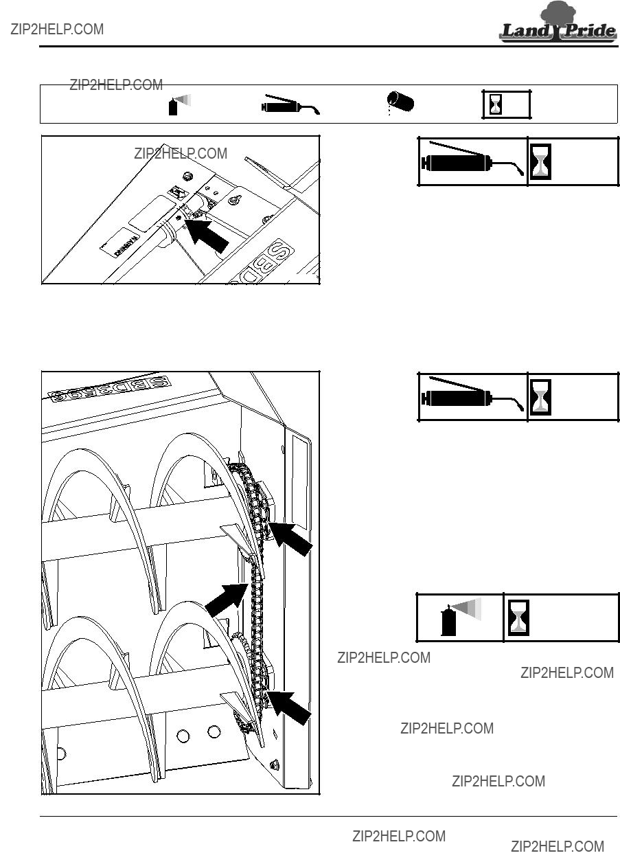
6.Lubricate as noted in ???Lubrication??? starting on page 34.

7.Apply a coating of oil to the areas without paint due to high wear to minimize oxidation.

8.Store Snow Blower on a level surface in a clean, dry place. Inside storage will reduce maintenance and make for a longer Snow Blower life.

9.Follow all ???Unhooking Snow Blower??? instructions on page 19 when disconnecting Snow Blower from tractor.

Order Replacement Parts

Land Pride offers equipment in factory standard beige with black highlights. Equipment may also be purchased in orange. Special attention must be given to the part number to prevent ordering the wrong color. A suffix number corresponding to one of the colors below must be added at the end of the part number. Parts ordered without the suffix number will be supplied in factory standard colors.

For example, if you are ordering a replacement part with part number 555-555C and the existing part is orange, then add the suffix 82 to the end of the number to make the part number read 555-555C82.

Table of Contents

Section 5: Maintenance & Lubrication

Table of Contents

Section 5: Maintenance & Lubrication

33293

Fill Plug

Level Plug

Do Not Overfill

SB3596 Gearbox

Level Plug

Do Not Overfill

SB35108 Gearbox

33294

NOTE: Use a suction or siphon pump to drain gearbox of oil when an oil drain plug does not exist.

As

Required

Gearbox

NOTE: Do not overfill! Snow Blower should be level when checking oil. Oil expands when hot, therefore, always check oil level when cold.

NOTE: Use a suction or siphon pump to drain gearbox of oil when an oil drain plug does not exist.

Remove oil level plug shown with arrow. If oil is below bottom of plug hole, add recommended gear lube through fill plug hole until oil flows out of the hole. Reinstall and tighten oil level plug.

Type of Lubrication: 80-90W EP Gear Lube

Quantity = Fill until oil begins to flow out of oil level plug hole in gearbox.

10

Hours

Driveline U-joints

Grease every 10 hours of operation

2 - Zerks

Type of grease = Multi-Purpose Quantity = Coat Generously

Driveline Shear Bolt

Grease every 10 hours of operation

1 - Zerk

Type of grease = Multi-Purpose Quantity = Coat Generously

Table of Contents

Section 6: Specifications & Capacities

SBD35 Series

Specifications & Capacities

Table of Contents

Section 6: Specifications & Capacities

SBD3596 = 87-3/4"

SBD35108 = 90"

SBD3596 = 96"

SBD35108 = 108"

SBD3596 = 99-1/2" W/O SKID SHOES SBD35108 = 111 1/2" W/0 SKID SHOES

SBD3596 = 104-1/2" WITH SKID SHOES SBD35108 = 116 1/2" WITH SKID SHOES

SBD3596 = 68"

SBD35108 = 79 1/4"

35751

Table of Contents

Section 7: Features & Benefits

Table of Contents

Section 8: Troubleshooting

Troubleshooting Chart

Table of Contents

Section 9: Torque Values Chart

Torque Values Chart for Common Bolt Sizes

Torque tolerance + 0%, -15% of torquing values. Unless otherwise specified use torque values listed above.

Additional Torque Values

Table of Contents

Section 10: Warranty

Warranty

Land Pride warrants to the original purchaser that this Land Pride product will be free from defects in material and workmanship beginning on the date of purchase by the end user according to the following schedule when used as intended and under normal service and conditions for personal use.

Overall Unit: One year Parts and Labor

Auger, Impeller, Wear Bars & Skid Shoes: Considered wear items

This Warranty is limited to the repair or replacement of any defective part by Land Pride and the installation by the dealer of any such replacement part, and does not cover common wear items such as blades, belts, tines, etc. Land Pride reserves the right to inspect any equipment or parts which are claimed to have been defective in material or workmanship.

This Warranty does not apply to any part or product which in Land Pride???s judgment shall have been misused or damaged by accident or lack of normal maintenance or care, or which has been repaired or altered in a way which adversely affects its performance or reliability, or which has been used for a purpose for which the product is not designed. Misuse also specifically includes failure to properly maintain oil levels, grease points, and driveline shafts.Claims under this Warranty must be made to the dealer which originally sold the product and all warranty adjustments must be made through such dealer. Land Pride reserves the right to make changes in materials or design of the product at any time without notice.

This Warranty shall not be interpreted to render Land Pride liable for damages of any kind, direct, consequential, or contingent to property. Furthermore, Land Pride shall not be liable for damages resulting from any cause beyond its reasonable control. This Warranty does not extend to loss of crops, any expense or loss for labor, supplies, rental machinery or for any other reason.

No other warranty of any kind whatsoever, express or implied, is made with respect to this sale; and all implied warranties of merchantability and fitness for a particular purpose which exceed the obligations set forth in this written warranty are hereby disclaimed and excluded from this sale.

This Warranty is not valid unless registered with Land Pride within 30 days from the date of purchase by the end user.

IMPORTANT: The Online Warranty Registration should be completed by the dealer at the time of purchase. This information is necessary to provide you with quality customer service.

Corporate Office: P.O. Box 5060

Salina, Kansas 67402-5060 USA

www.landpride.com