Cover photo may show optional equipment not supplied with standard unit.
Cover photo may show optional equipment not supplied with standard unit.

Land Pride.
Table of Contents
Important Safety Information . . . . . . . . . . .1
Be Aware of Signal Words . . . . . . . . . . . . . . . . . . . 1
Safety Labels . . . . . . . . . . . . . . . . . . . . . . . . . . . . . 4
Introduction . . . . . . . . . . . . . . . . . . . . . . . .7
Application . . . . . . . . . . . . . . . . . . . . . . . . . . . . . . . 7
Using This Manual . . . . . . . . . . . . . . . . . . . . . . . . . 7
Terminology . . . . . . . . . . . . . . . . . . . . . . . . . . . 7
Definitions . . . . . . . . . . . . . . . . . . . . . . . . . . . . . 7
Owner Assistance . . . . . . . . . . . . . . . . . . . . . . . . . 7
Serial Number Plate . . . . . . . . . . . . . . . . . . . . . . . . 7
Further Assistance . . . . . . . . . . . . . . . . . . . . . . . . . 7
Section 1 Assembly and
Tools Required . . . . . . . . . . . . . . . . . . . . . . . . . . . 8
Assembly Preparation . . . . . . . . . . . . . . . . . . . . . . 8
Cutter Bar and Gearbox Lubrication . . . . . . . . . . . 8
Cutting Unit . . . . . . . . . . . . . . . . . . . . . . . . . . . . . 10
Support Stand . . . . . . . . . . . . . . . . . . . . . . . . . . . 10
Section 2 Operating . . . . . . . . . . . . . . . . .11
Attaching the Tractor . . . . . . . . . . . . . . . . . . . . . . 11
Transporting . . . . . . . . . . . . . . . . . . . . . . . . . . . . 12
Operating Check List . . . . . . . . . . . . . . . . . . . . . . 12
Working Position . . . . . . . . . . . . . . . . . . . . . . . . . 12
Mowing Instructions . . . . . . . . . . . . . . . . . . . . . . . 13
Adverse Field Conditions . . . . . . . . . . . . . . . . 13
Operating Instructions . . . . . . . . . . . . . . . . . . . . . 14
Section 4 Maintenance and Lubrication .17
General Maintenance . . . . . . . . . . . . . . . . . . . . . . 17
At the beginning of each season: . . . . . . . . . . 17
Servicing Blades . . . . . . . . . . . . . . . . . . . . . . . . . 17
Blade Replacement . . . . . . . . . . . . . . . . . . . . . 17
Fastener Replacement . . . . . . . . . . . . . . . . . . 17
Cutter Bar Timing Adjustment . . . . . . . . . . . . . . . 18
Removal of one or more disc shaft assemblies 18
Assembly of entire cutting bar. . . . . . . . . . . . . 19
Storage . . . . . . . . . . . . . . . . . . . . . . . . . . . . . . . . 19
Lubrication . . . . . . . . . . . . . . . . . . . . . . . . . . . . . . 20
Driveline . . . . . . . . . . . . . . . . . . . . . . . . . . . . . 20
Driveline
Gearbox . . . . . . . . . . . . . . . . . . . . . . . . . . . . . 20
Cutter Bar . . . . . . . . . . . . . . . . . . . . . . . . . . . . 21
Frame Pivot Point . . . . . . . . . . . . . . . . . . . . . . 21
Hitch Pivot Point . . . . . . . . . . . . . . . . . . . . . . . 21
Section 5 Specifications and Capacities 22
Section 7 Troubleshooting . . . . . . . . . . .23
Section 8 Appendix . . . . . . . . . . . . . . . . .24
Torque Values Chart For Common Bolt Size . 24
Warranty . . . . . . . . . . . . . . . . . . . . . . . . . . . . . 25
?? Copyright 2008 All rights Reserved
Land Pride provides this publication ???as is??? without warranty of any kind, either expressed or implied. While every precaution has been taken in the preparation of this manual, Land Pride assumes no responsibility for errors or omissions. Neither is any liability assumed for damages resulting from the use of the information contained herein. Land Pride reserves the right to revise and improve its products as it sees fit. This publication describes the state of this product at the time of its publication, and may not reflect the product in the future.
Land Pride is a registered trademark.
All other brands and product names are trademarks or registered trademarks of their respective holders.
Printed in the United States of America.

Important Safety Information
These are common practices that may or may not be applicable to the products described in this manual.
Be Aware of Signal
Words
A signal word designates a degree or level of hazard seriousness. The signal words are:
! DANGER!
Indicates an imminently hazardous situation which, if not avoided, will result in death or serious injury. This signal word is limited to the most extreme situations, typically for machine components that, for functional purposes, cannot be guarded.
! WARNING!
Indicates a potentially hazardous situation which, if not avoided, could result in death or serious injury, and includes hazards that are exposed when guards are removed. It may also be used to alert against unsafe practices.
! CAUTION!
Indicates a potentially hazardous situation which, if not avoided, may result in minor or moderate injury. It may also be used to alert against unsafe practices.
Keep Riders
Off Machinery
???Riders obstruct the operator???s view, they could be struck by foreign objects or thrown from the machine.
???Never allow children to operate equipment.
!
??? Detach and store implements in a area where children normally do not play. Secure implement by using blocks and supports.

Important Safety Information
Land Pride
These are common practices that may or may not be applicable to the products described in this manual.
Use Safety
Lights and Devices
???Slow moving tractors, self- propelled equipment, and towed implements can create a hazard when driven on public roads. They are dif???cult to see, especially at night.
???Flashing warning lights and turn signals are recommended whenever driving on public roads.
Transport
Machinery Safely
???Comply with state and local laws.
???Maximum transport speed for implement is 20 mph. DO NOT EXCEED. Never travel at a speed which does not allow adequate control of steering and stopping. Some rough terrains require a slower speed.
???Sudden breaking can cause a towed load to swerve and upset. Reduce speed if towed load is not equipped with breaks.
???Use the following maximum speed - tow load weight ratios as a guideline:
???20 mph when weight is less than or equal to the weight of tractor.
???10 mph when weight is double the weight of tractor.
???IMPORTANT: Do not tow a load that is more than double the weight of tractor.
Practice Safe Maintenance
???Understand procedure before doing work. Use proper tools and equipment, refer to Operator???s Manual for additional information.
???Work in a clean dry area.
???Lower the implement to the ground, put tractor in park, turn off engine, and remove key before performing maintenance.
???Allow implement to cool completely.
???Do not grease or oil implement while it is in operation.
???Inspect all parts. Make sure parts are in good condition & installed properly.
???Remove buildup of grease, oil or debris.
???Remove all tools and unused parts from implement before operation.
Tractors With Cabs
Tractors Equipped With
ROPS
???There should be suf???cient clearance for the operator when mounted to a tractor with a cab or that is equipped with ROPS.
???The ROPS may need to be extended or ???ipped around to obtain suf???cient clearance.

Important Safety Information
These are common practices that may or may not be applicable to the products described in this manual.
Prepare for Emergencies
???Be prepared if a ???re starts.
???Keep a ???rst aid kit and ???re extinguisher handy.
???Keep emergency numbers for doctor, ambulance, hospital and ???re department near phone.
Wear
Protective Equipment
???Protective clothing and equipment should be worn.
???Wear clothing and equipment appropriate for the job. Avoid loose ???tting clothing.
???Prolonged exposure to loud noise can cause hearing impairment or hearing loss. Wear suitable hearing protection such as earmuffs or earplugs.
???Operating equipment safely requires the full attention of the operator. Avoid wearing radio headphones while operating machinery.
Tire Safety
???Tire changing can be dangerous and should be performed by trained personnel using the correct tools and equipment.
???When in???ating tires, use a
???When removing and installing wheels, use wheel handling equipment adequate for the weight involved.
911
Safety at All Times
Thoroughly read and understand the instructions given in this manual before operation. Refer to the ???Safety Label??? section, read all instructions noted on them.
???Operator should be familiar with all functions of the unit.
???Operate implement from the driver???s seat only.
???Do not leave tractor or implement unattended with engine running.
???Dismounting from a moving tractor could cause serious injury or death.
???Do not stand between the tractor and implement during hitching.
???Keep hands, feet, and clothing away from
???Wear snug ???tting clothing to avoid entanglement with moving parts.
???Turning tractor too tight may cause implement to ride up on wheels. This could result in injury or equipment damage.
Important Safety Information
Land Pride
Safety Labels
Your Mower comes equipped with all safety labels in place. They were designed to help you safely operate your implement.
1.Read and follow label directions.
2.Keep all safety labels clean and legible.
3.Replace all damaged or missing labels.
4.Some new equipment installed during repair require safety labels to be affixed to the replaced component as specified by Land Pride. When ordering new components make sure
the correct safety labels are included in the request. To order new labels go to your Land Pride dealer.
5.Refer to this section for proper label placement. To install new labels:
a.Clean the area the label is to be placed.
b.Spray soapy water on the surface where the label is to be placed.
c.Peel backing from label. Press firmly onto the surface.
d.Squeeze out air bubbles with the edge of a credit card.
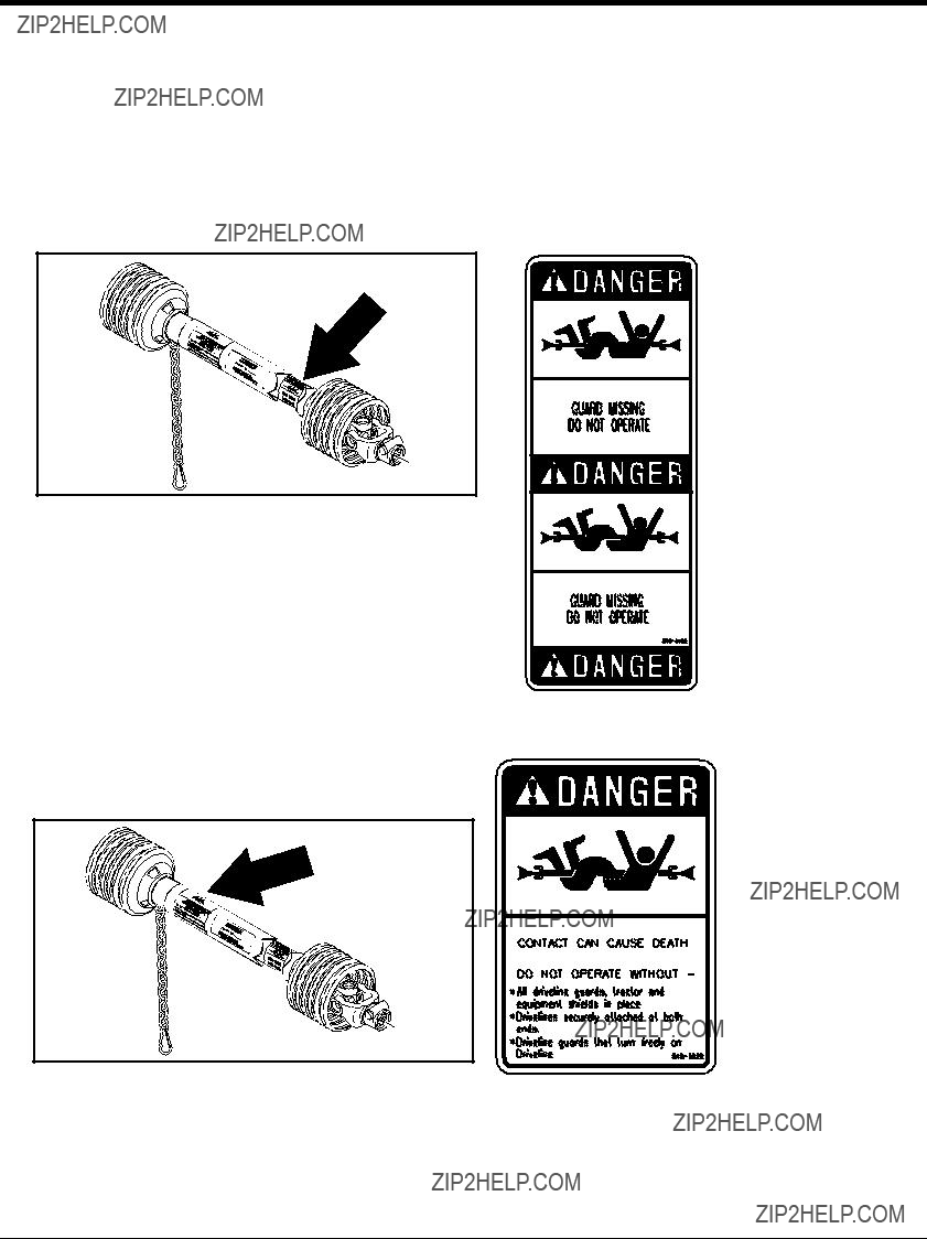
Danger Guard Missing
ROTATING DRIVELINE
KEEP AWAY!
Danger PTO Driveline

Important Safety Information
Danger Crushing Hazard

Important Safety Information
Land Pride
Warning General Mower Safety
Warning Rotating Disc
Land Pride
Introduction
Land Pride welcomes you to the growing family of new product owners.
This Disc Mower has been designed with care and built by skilled workers using quality materials. Proper assembly, maintenance, and safe operating practices will help you get years of satisfactory use from the machine.
Application
The Land Pride Disc Mowers are designed and built to cut hay, grass, and other cultivated forage crops on farms, ranches,
Land Pride Disc Mowers will typically cut faster than traditional sickle bar mowers and are designed to deliver good cutting performance even in thick, tangled, and wet grass conditions. Fire Ant hills and Gopher mounds, that may tend to clog traditional
Land Pride Disc Mowers are well suited for use in agricultural regions where humidity and moisture conditions are typically higher and the potential for crop entanglement and tough ground conditions are present. See ???Features and Bene???ts???, ???Section 5??? for additional information.
Using This Manual
???This Operator???s Manual is designed to help familiarize you with safety, assembly, operation, adjustments, troubleshooting, and maintenance. Read this manual and follow the recommendations to help ensure safe and efficient operation.
???The information contained within this manual was current at the time of printing. Some parts may change slightly to assure you of the best performance.
???To order a new Operator???s or Parts Manual contact your authorized dealer. Manuals can also be downloaded,
Terminology
"Right" or "Left" as used in this manual is determined by facing the direction the machine will operate while in use unless otherwise stated.
De???nitions
NOTE: A special point of information that the operator must be aware of before continuing.
IMPORTANT: A special point of information related to its preceding topic. Land Pride???s intention is that this information should be read and noted before continuing.
Owner Assistance
The Warranty Registration card should be ???lled out by the dealer at the time of purchase. This information is necessary to provide you with quality customer service.
If customer service or repair parts are required contact a Land Pride dealer. A dealer has trained personnel, repair parts and equipment needed to service the disc mower.
The parts on your disc mower have been specially designed and should only be replaced with genuine Land Pride parts. Therefore, should your disc mower require replacement parts go to your Land Pride Dealer.
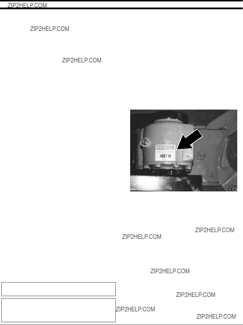
Serial Number Plate
For prompt service always use the serial number and mod- el number when ordering parts from your Land Pride deal- er. Be sure to include your serial and model numbers in correspondence also. Refer to Figure 1 for the location of your serial number plate.
Further Assistance
Your dealer wants you to be satis???ed with your new disc mower. If for any reason you do not understand any part of this manual or are not satis???ed with the service received, the following actions are suggested:
1.Discuss the matter with your dealership service manager making sure he is aware of any problems you may have and that he has had the opportunity to assist you.
2.If you are still not satis???ed, seek out the owner or general manager of the dealership, explain the problem and request assistance.
3.For further assistance write to:
Land Pride
Service Department
P.O. Box 5060
Salina, KS

Section 1 Assembly and
Land Pride
Tools Required
???Fork lift, crane hoist or
???Impact wrench or socket and ratchet set (metric)
???Rubber mallet
???
???Drift pins
???Screwdriver
???Safety shoes, safety glasses and gloves. A hard hat should be worn by anyone working under the crane.
Cutter Bar and Gearbox Lubrication
The cutter bar should arrive with oil already added. After assembly you may want to check to make sure. For instructions on how to do this see Lubrication in ???Section 4 Maintenance and Lubrication??? on page 17 and ???Section 5 Speci???cations and Capacities??? on page 22.
Before operating this unit add SAE 80 GL4 (EP) oil to gearbox. For further instructions see Lubrication in
???Section 4 Maintenance and Lubrication??? on page 17 and ???Section 5 Speci???cations and Capacities??? on page 22.
Assembly Preparation
Having all the parts and equipment readily at hand will speed up your assembly task and make the job as safe as possible.
Prepare the area where the unit is to be assembled mak- ing sure the area is swept clean of all dust and contami- nants.
NOTE: Remove heavy components from crate with a hoist or
Raise the mainframe with a forklift, hoist or
Your cutter bar will already be assembled. It is necessary to check the direction of rotation of each cutter plate. Figure
15144
Cutter Bar Plate Rotation
Figure
It is also necessary to check whether the plate turning right has right cutter blades and the plate turning left has left cutter blades.
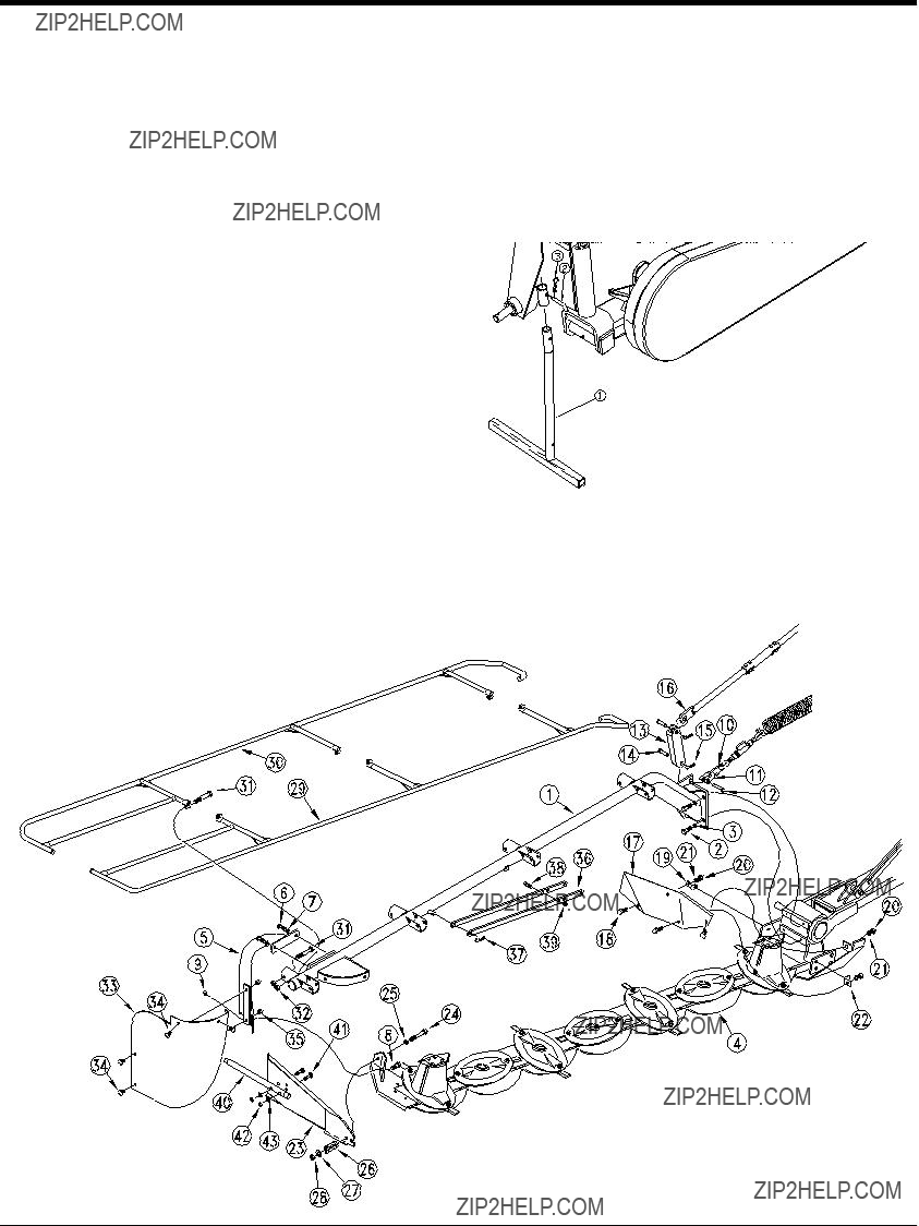
Refer to Figure
1.Insert bushing (#1) into mainframe (#7) and slide over gearbox as shown.
2.Insert the pivot plate (#43) that is already assembled to the cutter unit (#2) onto the mainframe studs and secure with bolts (#3) and washers (#4).
3.Insert the release arm (#8) between the lugs on the mainframe and secure with pin (#12), washers (#13) and cotter pins (#14). Install the bushing (#10) and the chain(#9) on the hitch pin. Insert the other end of the release arm (#8) on to the hitch pin as shown.
4.Assemble the tie rod (#41) to the mainframe lugs as shown using the pin (#5) and roll pin (#6). The other end is already assembled.
5.Place the pulley mount (#15) on the mainframe as shown. Install belt (#23) on both pulleys. Insert the belt tightening rod (#18) into the pulley mount (#15). Slide the pulley mount on the mainframe until the belt tightening rod (#18) can be inserted into the hole of the mainframe lug and retain with nut (#19). Install
6.Install the bottom and top belt guards (#24) and (#25) to the mainframe using the bolt (#26), washer (#27), nut (#33) stud bolts (#28) and external tooth washers (#29).
7.Assemble the outer belt shield (#32) to the stud bolts (#28) and retain with wing nuts (#30) and washers (#31).
8.Assemble the hydraulic cylinder (#39) on to the pin (#42) that is in the top spring support bracket. Retain with pin (#40).
Section 1 Assembly and
Main Frame Dealer Assembly
17877
Figure
Section 1 Assembly and
Land Pride
Cutting Unit
Refer to Figure
1.Install the support frame (#1) to the gearbox using the bolts (#2) and washers (#3).
2.Assemble the support leg (#5) to the support frame (#1) using the bolts (#6) and washers (#7). Assemble the support leg (#5) to the cutting unit (#4) and secure with bolt (#8) and lock nut (#9).
3.Assemble the clevis (#11) on the support frame lug and retain with pin (#12) as shown.Loosen nut on D- ring (#10) that is at the end of the spring stretcher and install on the clevis (#11).
4.Install the cylinder bracket (#13) on to the support frame (#1) using the pin (#14) and hair pin cotter (#15) to secure. Assemble the other end of the cylinder (#16) to the cylinder bracket (#13) and secure with pin (#14) and hair pin cotter (#15).
5.Attach the shield (#17) as shown using the brackets (#19) and (#22). Secure with bolts (#18), washers (#21) and nuts (#20).
6.Assemble the guide (#23) to the cutting unit (#4) with the bolt (#24), washer (#25), ???at washer (#27) and lock nut (#28). Place the spring (#26) between the guide (#23) and ???at washer (#27).Attach the guide rod (#40) to the guide (#23) with the carriage bolts (#41), washers (#43) and lock nuts (#42).
7.Assemble the front tarp frame (#29) and rear tarp frame (#30) to the support frame (#1) using bolts (#31) and nuts (#32) to secure.
8.Assemble the shield (#33) to the support frame (#1) and support leg (#5) using the carriage bolts (#34) and nuts (#35) to secure.
Support Stand
Refer to Figure
Insert stand (#1) into tube on the hitch as shown and secure with pin (#2) and hair pin cotter (#3).
17895
Support Stand
Figure
Land Pride
Section 2 Operating
Attaching the Tractor
1.Back the tractor up to the disc mower so that the lower draft arms are aligned with the lower lift pins of the disc mower. Connect
2.Raise the mower cutter bar off the ground slightly by actuating the hydraulic cylinder.
3.Adjust the length of the tractor???s two sway link arms to prevent swaying from side to side.
4.Attach the chain to the top link of tractor making sure the PTO driveline is level.
5.If necessary use the adjustment on the lower
6.Raise the support leg and position it in the high position.
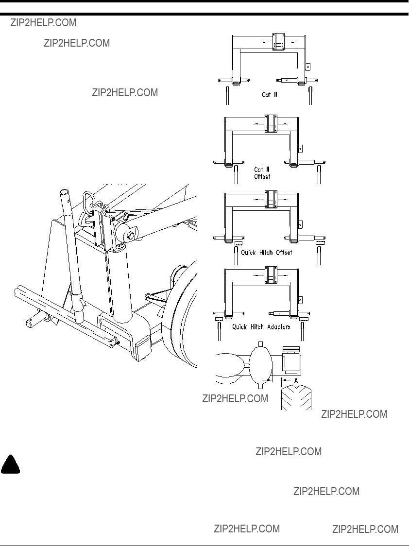
Tractor
Figure
For Category II attachment, line up lower draft arms of tractor. Attach to pins and retain with clip pins. Position top hitch as necessary. Be sure roll pin is installed thoroughly.
For Category II Offset attachment, remove the roll pin and slide the left bottom pin. Reinstall roll pin. Line up lower draft arms of tractor. Attach to pins and retain with clip pins. Position top hitch as necessary.
For Quick Hitch Adapters slide adapter bushings over pins. For Offset Quick Hitch, remove roll pins and slide the left bottom pin and rotate the right pin. Reinstall roll pins. Line up lower draft arms of tractor. Attach to pins and retain with clip pins. Position top hitch as necessary.
Attach machine so that ???A??? is approximately 4 inches.
! WARNING
Be sure the driveline is properly connected. A loose yoke could slip and cause personal injury or damage to the mower.

Land Pride
! CAUTION
When traveling on public roads at night or during the day, use accessory lights and devices for adequate warning to operator's
Operating Checklist
of other vehicles. Comply with all federal, state and local laws.
IMPORTANT: Always disengage the tractor???s PTO before raising the mower to transport position.
NOTE: When raising the mower to the transport position be sure that PTO shaft does not contact tractor or mower.
Safety Rules
Operating Instructions
Check oil level in gearbox and cutter bar.
Check that all plugs in gearbox have been replaced properly.
Be sure nuts and bolts are tight.
Be certain all guards and shields are in place.
Lubricate mower as needed. Refer to
???Maintenance and Lubrication.???
Be sure all implement attaching points and hardware are secure and in place.
Check for Hydraulic Leaks
Operating Check List
In addition to design and con???guration of equipment; hazard control and accident prevention are dependent upon the awareness, concern, prudence and proper training involved in their operation, transport, maintenance and storage of equipment. Before beginning to cut the following inspection should be performed.
! DANGER
To avoid injury or death from entanglement in rotating drivelines, the drive gearbox shields must be in place and secure when operating.
! DANGER
Do not operate mower without the curtain completely in place around the cutter bar. Do no lean against or stand on the curtain.
Working Position
! WARNING
Before lowering cutter bar, make sure no one is within 20 feet of mower.
1.Lower mower using the tractor lift.
2.Retract cylinder and remove the pin from the ROAD lock position. Fold the transport lock arm and pin free end to curtain support arm.
Land Pride
Section 2 Operating
3.Release the hydraulic cylinder and lower the cutter bar until it is parallel to the ground.
4.Raise
5.Reposition curtain.
NOTE: Before using the mower, check the break- away linkage to make sure all components work correctly.
Mowing Instructions
NOTE: Although the mower is shielded to prevent objects from being thrown by the blades, no one shield is 100% effective. As a rule most people are not knowledgeable of the dangers of being around a disc mower while it is in operation. Therefore, the operator should always stop mowing when someone passes by.
! WARNING
Prolonged exposure to high sound levels require hearing protection. Wear hearing protection when operating this machine with open platform tractors.
Allow a few minutes for oil to spread in the cutter bar before engaging the PTO when changing from transport to operating position.
With the cutting bar on the ground, engage the PTO at low tractor idle and accelerate gradually to 540 rpm PTO speed.
If the cutter bar is operated at an angle for long periods of time, hold it horizontal for a few minutes every half hour or so of work to help lubricate gears at upper end of cutter bar.
Adapt forward speed to working conditions. Gear down when mowing in dense crops. Do not lower tractor rpm.
Adverse Field Conditions
! DANGER
Do not use machine in rocky or stony conditions.
Extra care and precaution should be taken in rough or
1.Tilt the angle of the cutter bar back towards the horizontal position by lengthening top link to raise the cutting height of the knives.
2.Reduce the forward speed.
3.Make sure the cutting blades can pivot if an obstruction is hit.
IMPORTANT: If an obstruction is hit, idle engine, disengage PTO, shut off tractor, remove ignition key and wait for all moving parts to come to a complete stop. Inspect the entire mower and repair any damage before resuming operation.
! CAUTION
Do not disengage PTO when engine is at full PTO rpm. Always idle engine before disengaging PTO.
IMPORTANT: ToSafety
The
To reset the cutter bar, back the mower slowly and carefully until breakaway latch repositions. The factory setting of the latch is adapted to most working conditions.
Check the cutter bar for any damage before resuming operation.
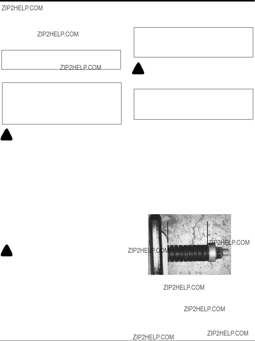
If the cutter bar continues to break away after resetting, the pressure of the spring assembly can be increased. In all cases the length must not be less than 3 3/8 inch or safety disengagement cannot function.
The stack of spring washers should be compressed to 3 3/8 inch. See Figure
 3 3/8???

Section 2 Operating
Land Pride
Operating Instructions
By now you should have thoroughly read your Disc Mower Operator???s Manual, properly attached your Land Pride Disc Mower to your tractor, and reviewed the Operating Checklist. If you have not yet completed all of these functions, please do so now.
Now that you???re properly briefed and your disc mower is ready, it???s time to transport to the field.
For transport purposes, your Disc Mower should be securely locked with the cutter bar in the upright or vertical position. Make sure the support leg is in the high position. A "Slow Moving Vehicle" sign should be in place and visible from the rear, if you are using a public road or
Once you have safely arrived at your hay field, position your tractor on level ground. Make sure that no one is within 20ft of the mower, as your prepare to lower the cutter bar from transport to working position. Lower the
Controlling or setting your cutting height is accomplished by adjusting the "top link" on you
If you do hit an object when you are mowing, immediately disengage the PTO, idle the engine, stop the tractor, wait for all moving parts to come to a complete stop, shut off the tractor, set the brake, remove the keys, and inspect for damage. If damage is present, make the necessary repairs. If no damage is present, but you have tripped the "Break Away Safety Latch, slowly reverse the tractor until the latch resets and proceed with mowing operations.
Prior to actually beginning cutting operations, you will want to get the mower up to full 540 rpm PTO speed by engaging the PTO with the tractor engine at idle and gradually increasing engine rpm to PTO speed. Once you reach the full 540 rpm, allow the mower to run for a few minutes at level position so the oil in the cutter bar can lubricate all internal moving parts. You will also want to take this opportunity to make a quick Operational Running Check. Listen and visually inspect for any component or part that may be loose or out of adjustment. Don???t be alarmed by the noise level of the free running Disc Mower. It will actually become quieter when you begin mowing and have some run in time on it.
If your Operational Running Check was ok, begin mowing operations by opening up the lands on your field. Make enough lands so you can easily make your turns to properly line up for each pass down the field. If your tractor and Disc Mower are set up right, you should be able to straddle the previous swath as you make each subsequent pass starting in the center of the field. If you do experience cutting problems, refer to the "Trouble Shooting" section of your Operator???s Manual for corrective action.
When your done mowing for the day and need to transport the mower to your storage site, simply reverse the process you used to take the mower out of transport mode. When you are done mowing for the season, clean and lubricate your mower, replace warn or missing parts, release tension on the belts, and store the unit with the cutter bar in the horizontal working position. You will get longer service life out of your mower by storing it inside and repainting scratched or rusted components.
With a little practice and experience you should become very good at operating your Land Pride Disc Mower.

Land Pride
Section 3 Adjustments
! DANGER
Check tightness of the belt regularly, especially when working the ???rst few hours.
Before making any adjustments to this machine, disengage PTO, shut off tractor, remove ignition key and wait for all moving parts to stop. Disconnect the PTO driveline.
Leveling for Transport and Operation
The elevating arm and retaining arm need to be adjusted together. See Figure
Belt Tension Adjustment
Belt must be properly tensioned at all times to avoid excessive ???opping and slipping. Loose belt will also cause poor cutting and premature wear.
Always retighten or check belt after
Refer to Figure
1.Loosen
2.Tighten nut (#2) on the belt tension rod (#3) until you have a 3/4??? de???ection midpoint between pulleys. Refer to Figure
3.Retighten nut on

Section 3 Adjustments
Land Pride
Cutting Height
Refer to Figure
Cutting height can be adjusted with the upper
Maximum cutting height of 2??? is achieved when the discs are parallel to the ground. Adjustment of cutting height is achieved by altering the cutter bar tilt angle. This is done
by varying the upper
To minimize blade and disc wear, improve grass regrowth and get maximum nutritive value from the crop, minimum cutting height should never be adjusted less than 1 1/4???.
15091
Cutting Height
Figure
Section 4 Maintenance and Lubrication
General Maintenance
Proper servicing and adjustment is the key to the long life of any farm implement. With careful and systematic inspection, you can avoid costly maintenance, time and repair.
! DANGER
Before servicing this machine, turn off the tractor engine, remove the ignition key and disconnect the PTO driveline.
Each new machine should be checked after the ???rst 10 hours of work. All screws and bolt torques should be routinely checked.
At the beginning of each season:
1.Check and/or change the oil; lubricate or grease all points. See Lubrication in this section.
2.Check blade wear and condition of their fasteners, see
???Servicing Blades???, page 17.
3.Check wear on guards and curtain.
4.Retention belts, see ???Belt Tensioning Adjustment???, page 15.
5.Check all screws and bolts to be sure they are tight.
Servicing Blades
Cutting quality as well as safe operation depend on the regular inspection and care given to the knives.
! WARNING
To avoid personal injury when the blades and/or carrier are being serviced, always block the mower up to prevent it from falling.
Check blades for cracks and wear and blade bolts for tightness daily. Blades should be replaced when they are worn excessively, bent, nicked, deformed, or out of balance.
NOTE: Blade bolts should be tightened to 55
NOTE: Always replace damaged blades. Never straighten a bent blade. Never replace one knife only per disc. Always replace both of them to avoid creating an
! CAUTION
When changing blades, always replace the blade bolt & blade nut together at the same time. Worn or damaged blade bolts or nuts could fail in a hazardous manner that could cause injury.
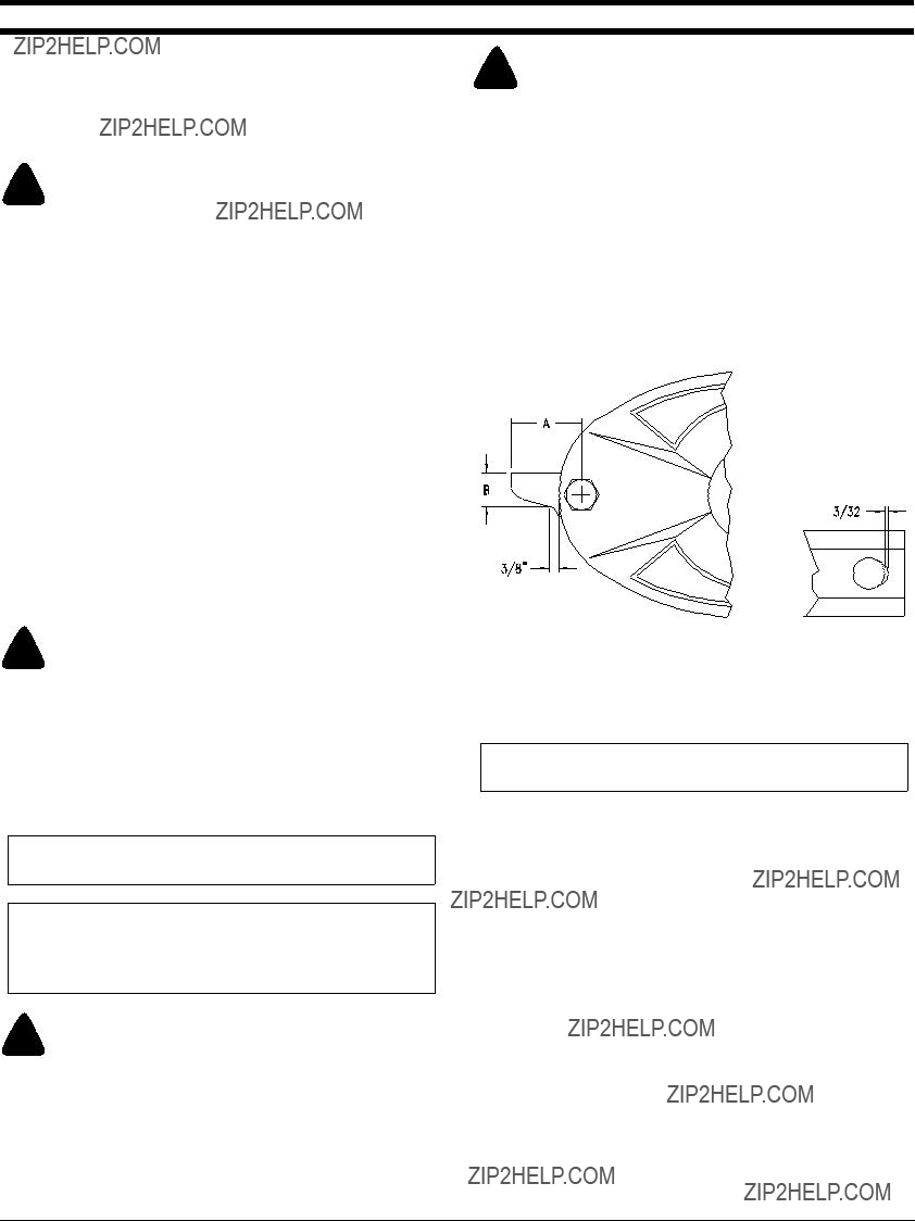
Blade Replacement
1.See Figure
1 5/16??? (B) wide at a distance of 3/8??? from the disk. The length (A) of the blade should be greater than 2 1/2???.
2.See Figure
Fastener Replacement
NOTE: Always replace blade bolts and nuts when they have been removed 5 times.
1.Replace fasteners when a visible deformation is found.
2.See Figure
3.Replace bolts when the ???at sides at the bolt ???ange are excessively worn or missing altogether.
4.See Figure
5.See Figure
! CAUTION
Replace with Land Pride blades only. Substitute blades may not meet speci???cations and may fail in a hazardous manner that could cause injury.
6.Replace Belleville washers on breakaway if they are ???attened.

Section 4 Maintenance and Lubrication
Land Pride
Cutter Bar Timing Adjustment
Removal of one or more disc shaft assemblies
Refer to Figure
1.Rotate the long axis of the discs adjacent to the replaced shaft assembly 90 degrees to the long axis of the cutter bar.
2.Locate the round reference punch mark on the underside of the gear. Orient the reference mark parallel to the long axis of the cutter bar (90 degrees to the axis of the adjacent discs).
Disc Assembly
Figure
10441
Section 4 Maintenance and Lubrication
NOTE: The reference punch mark is round. Ignore any rectangular marks.
3.Apply sealant to the shaft assembly housing. Attach the shaft assembly housing to the cutter bar maintaining parallel alignment of the reference mark and cutter bar.
4.Install the disc on the shaft perpendicular to the adjacent discs.
Assembly of entire cutting bar.
Refer to Figure
1.Carefully clean all parts to remove sealant, dirt, and metal contamination.
2.Set the gearbox onto the cover. Set the shaft assemblies onto the cover.
3.Apply sealant to the underside of the shaft support housing and tighten the nuts.
4.Turn the cover over and set the idler gears (C) onto the inserts in the cover.
5.Align the punched reference mark on the ???rst pinion
(B) with the center line of the bar.
6.Rotate the second pinion until the punched reference is perpendicular to the ???rst pinion.
7.Alternate alignment of the reference marks down the bar.
8.Place the idler gears (D) into the inserts. Set the lower half of the cutter bar on the cover and seal the contact areas between the two halves. Wait a few hours before applying the gear lubricant.
Storage
At the end of the working season or when the mower will not be used for a long period, it is good practice to clean off any dirt or grease that may have accumulated on the mower and any of the moving parts.
1.Clean the Disc Mower as necessary.
2.Check the blades and blade fasteners for wear and replace if necessary, see ???Servicing Blades???, Page 17.
3.Inspect the mower for loose, damaged or worn parts and adjust or replace as needed.
4.Lubricate as noted in ???Section 4 Maintenance and Lubrication??? on page 17.
5.Release tension on drive belts.
6.Store cutter bar in horizontal (operating) position.
7.Store the Disc Mower inside if possible for longer Disc Mower life.
8.Repaint parts where paint is worn or scratched to prevent rust.
Cutter Bar Assembly
Figure
10441

Section 4 Maintenance and Lubrication
Land Pride
Lubrication
Lubrication
Legend


 20
20
Driveline
Quantity = Clean & coat the inner tube of the driveline with a light ???lm of grease and then reassemble.


 8
8
Driveline
Type of Lubrication: Grease
As
Required

Section 4 Maintenance and Lubrication
As
Required
Cutter Bar
Check oil level in the cutter bar by removing the ???ller level plug. With cutter bar in transport position, use a 5/16??? or 8mm allen wrench to remove plug. (The plug is located between the ???rst and second discs on DM3506 and between the second and third discs on DM3507.) If the oil level is low, add oil.
15154
NOTE: Do not over???ll. Mower should be level and cutter bar vertical when checking oil. Be sure to let cutting bar set in vertical position for a few minutes before checking to allow time for oil to ???ow to the bottom of bar.
Type of Lubrication: SAE 80 GL4 (EP) gear lube
Quantity =???ll until level with in ???ller level plug hole.


 20
20
Frame Pivot Point
Type of Lubrication: Grease


 20
20
Hitch Pivot Point
Type of Lubrication: Grease

Section 8 Appendix
Land Pride
Torque Values Chart For Common Bolt Size
Torque tolerance + 0%,

Land Pride
Section 8 Appendix
Warranty
Land Pride warrants to the original purchaser that this Land Pride product will be free from defects in material and workmanship beginning on the date of purchase by the end user according to the following schedule when used as intended and under normal service and conditions for personal use.
Overall Unit and Driveline: One year Parts and Labor
Gearbox: 5 years on housing, gears and shafts
3 years on seals & bearings
Blades and driveline friction discs considered wear items
This Warranty is limited to the replacement of any defective part by Land Pride and the installation by the dealer of any such replacement part, and does not cover common wear items such as blades, belts, tines, etc. Land Pride reserves the right to inspect any equipment or parts which are claimed to have been defective in material or workmanship.
This Warranty does not apply to any part or product which in Land Pride???s judgment shall have been misused or damaged by accident or lack of normal maintenance or care, or which has been repaired or altered in a way which adversely affects its performance or reliability, or which has been used for a purpose for which the product is not designed. Misuse also specifically includes failure to properly maintain oil levels, grease points, and driveline shafts.
Claims under this Warranty must be made to the dealer which originally sold the product and all warranty adjustments must be made through such dealer. Land Pride reserves the right to make changes in materials or design of the product at any time without notice.
This Warranty shall not be interpreted to render Land Pride liable for damages of any kind, direct, consequential, or contingent to property. Furthermore, Land Pride shall not be liable for damages resulting from any cause beyond its reasonable control. This Warranty does not extend to loss of crops, any expense or loss for labor, supplies, rental machinery or for any other reason.
No other warranty of any kind whatsoever, expressed or implied, is made with respect to this sale; and all implied warranties of merchantability and fitness for a particular purpose which exceed the obligations set forth in this written warranty are hereby disclaimed and excluded from this sale.
This Warranty is not valid unless registered with Land Pride within 30 days from the date of purchase by the end user.

Corporate Of???ce: P.O. Box 5060
Salina, Kansas
www.landpride.com