TIME LAPSE VCR
SERVICE MANUAL
CAUTION
BEFORE SERVICING THE UNIT, READ THE ???SAFETY PRECAUTIONS???
IN THIS MANUAL.
APRIL, 2006
Printed in Korea
TIME LAPSE VCR
SERVICE MANUAL
CAUTION
BEFORE SERVICING THE UNIT, READ THE ???SAFETY PRECAUTIONS???
IN THIS MANUAL.
APRIL, 2006
Printed in Korea

TABLE OF CONTENTS

*Designs and specifications are subject to change without notice.
*Weight and dimensions shown are approximate.
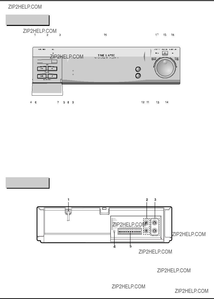
SECTION1 SUMMARY
LOCATION OF CUSTOMER CONTROLS
FRONT
REAR

SECTION1 SUMMARY
LOCATION OF CUSTOMER CONTROLS
INDICATOR PANEL
VCR FUNCTION INDICATION
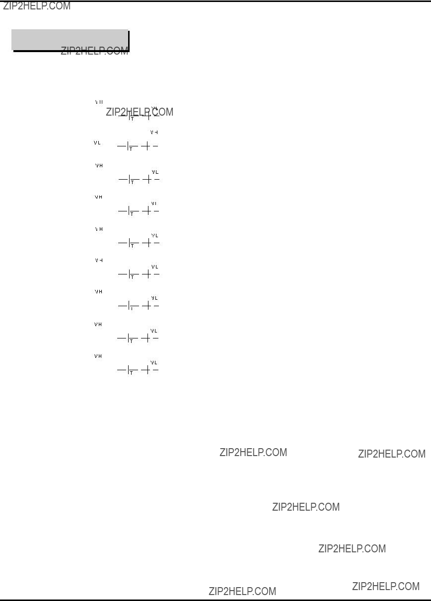
SECTION1 SUMMARY
LOCATION OF CUSTOMER CONTROLS
TERMINAL SIGNAL LEVELS

SECTION1 SUMMARY
CRITICAL PARTS REPLACING TIME TABLE
Notes :
???Check the running path adjustment when you change the itens 1, 3, 5, 6 and 10.
???Check the back tension when you change Band Assy Tension.
CRITICAL PARTS DESCRIPTION
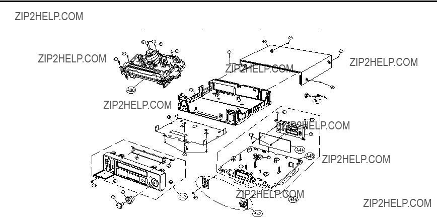
SECTION2 CABINET & MAIN FRAME
EXPLODED VIEWS
1. Cabinet and Main Frame Section
Cabinet & Main Frame Section Parts list

SECTION2 CABINET & MAIN FRAME
EXPLODED VIEWS
Cabinet & Main Frame Section Parts list
ASSEMBLY PARTS SECTION

SECTION2 CABINET & MAIN FRAME
EXPLODED VIEWS
2. Packing & Accessory Section
??? NOTE
Refer to ???REPLACEMENT PARTSLIST??? in order to look for the part number of each part.
802:BOX CARTON
???Packing Accessory Section Parts list
SECTION3 ELECTRICAL
ELECTRICAL ADJUSTMENT PROCEDURES
1. PG ADJUSTMENT
1. Connect
and adjust it to
2.Connect
(In case of 10:1 Probe, adjust it 50
3.Adjust time of the oscilloscope to 0.1 msec.
4.Adjust the range between FLLING EDGE part of video vertical trigger signal and video vertical trigger signal to the specification(416??20 sec) with changing VR501.
???CONNECTION CHART OF MAIN PWB
Fig
??? Caution
When repairing the power part just after pulling out the power code, there is hazard of electical shock caused by the charged electricity at the peripheral circuit component(primary power) such as condenser C807(150???F). So begin repairing after doing procedure below.
1.Set the volt meter up to resistance measurement.(In case of digital volt meter, set it up to over 20M??.)
2.Discharge electicity with putting the measuring terminal lines(+, 1 probe) of volt meter at the ends of condenser C103.(You don???t have to put the polarity of the measuring terminal lines on the same polarity of the condenser.)
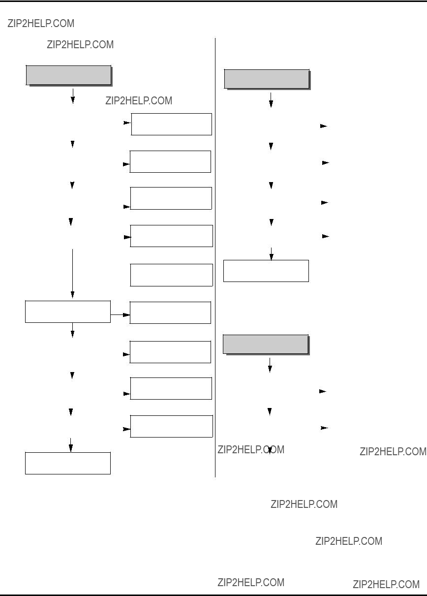
SECTION3 ELECTRICAL
ELECTRICAL TROUBLESHOOTING GUIDE
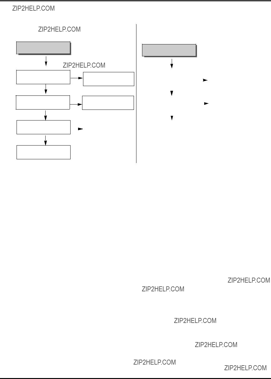
1. Power Circuit(SMPS)
(1) No 5.3 A
No 5.3V
Replace F101(Use a specified fuse).
Replace BD101.
Replace R101.
Is D103 normal?
 NO
NO
Check/
Replace D103
(2) No 9V
No 12V
YES
Check/ Replace Q163
YES
Is D106 normal?
YES
NO
Replace D106.
(3) No 24 V
YES
Check the power terminal at main
PCB short.
Replace IC103.
Replace D109.
Is L103 normal?
No 24V
SECTION3 ELECTRICAL
ELECTRICAL TROUBLESHOOTING GUIDE
(4) No 5.2 A (TO AVCP, BIAS)
(5) No 10V
No 5.2V
Is D106 normal?
YES
Is Q153 normal?
YES
Is there voltage (about 0V) at Q157 collector.
YES
Check/
Replace Q156
NO
Replace D106.
NO
Replace Q153.
No 10V
SECTION3 ELECTRICAL
ELECTRICAL TROUBLESHOOTING GUIDE
2.SERVO CIRCUIT
(1)Video is unstable in PB mode
In PB mode
Does noise level on the screen change periodically?
YES
IC501 Pin 76?
YES
NO
Does CTL pulse move on tracking?
YES
Does Video Envelope wave form NO appear at IC501 pin 86?
YES
Replace IC501.
Replace IC501.
Check the
(2) Drum motor stops
When the drum moter stop
NO
YES
YES
Aren???t pattern or componets between
IC501 Pin34 and PMC01 Pin12 short?

SECTION3 ELECTRICAL
ELECTRICAL TROUBLESHOOTING GUIDE
(3) Capstan motor stops
When the capstan motor stops
NO
Is it 12VA at PMC01 Pin2?
YES
NO
Is there 2.8V at PMC01 Pin9?
Check Power circuit
Does PWM signal appear at IC501 Pin 33?
YES
Aren???t pattern or componets between
IC501 Pin33 and PMC01 Pin1 short?

SECTION3 ELECTRICAL
ELECTRICAL TROUBLESHOOTING GUIDE
3. Y/C CIRCUIT
(1) No Video in EE Mode
No Video in EE Mode
Check the Video input Jack &
jack Board connection.
Check the IC3G1 Pin14
and Q3G1 emitter.
YES
Is 5V applied to the
NO
Check the 5VA Line.
IC301 Pin16, 40, 55, 58, 75, 87?
(Power Circuit)
YES
Does the Video signal appear at the IC301 Pin29?
YES
NO
YES
NO
Does the Video signal appear at the Emitter terminal of the Q380?
YES
Replace the Q380.
Check the 9V Line.
(Power Circuit)

SECTION3 ELECTRICAL
ELECTRICAL TROUBLESHOOTING GUIDE
(2) When the Y(Luminance)signal doesn???t appear on the screen in PB Mode.
Is 5V applied to the IC301 Pin 16, 40, 55, 58, 87?
Is the I2C Bus signal applied to the IC301 Pin 23, 24?
YES
YES
Is the V.H.S/W "H" about
3.4V to the IC301 Pin11 ?
YES
Is V.H.S/W "H" about 3.4V at the IC301 Pin 11?
YES
Clean the Drum.
NO
Check the V.H.S/W level. (Check R304, R305)
NO
Replace the IC301.
YES
NO
Is the Y(Luminance) Video waveform
showed up at the IC301 Pin 41?
YES
Replace the IC301.

SECTION3 ELECTRICAL
ELECTRICAL TROUBLESHOOTING GUIDE
(3) When the C(Color) signal doesn't appear on the screen in PB Mode
Is 5V applied to the IC301 Pin 16, 40, 55, 58, 87?
Is the Color Rotary signal applied to the IC301 Pin 10?
YES
NO
NO
Check the line of the 5.3VA Line. (Power Circuit)
Check the Color Rotary
Circuit. (IC501 pin 98)
YES
YES
YES
Does the Color signal appear at the IC301 Pin 61?
YES
Check the circuit of the
Replace the IC301.
IC301 Pin 35, 62.
(4) When the Video signal doesn't appear on the screen in REC Mode.
YES
Does PB Mode operate normally?
YES
Does the RF signal appear at the IC301 Pin 12?
YES
Does the REC RF signal appear at the IC301 Pin90?
YES
Check the Drum &
Drum Connector
NO
NO
NO
Check PB Mode.
Is the REC 'H' signal (about 4V)applied to the IC301 Pin 30?
YES
Check REC Luminance
Pass & Color Pass.
Check the circuit of the
IC301 Pin 90, 92, 94
YES

SECTION3 ELECTRICAL
ELECTRICAL TROUBLESHOOTING GUIDE
4. AUDIO CIRCUIT
(1) No sound in EE Mode
No sound in EE Mode.
YES
No sound.
YES
(2) No sound in PB MODE
No sound in PB Mode.
YES
No sound.
YES
YES
YES
Does the CLK/Data signal(I2C) appear at the IC301 Pin 23, 24?
YES
NO
NO
Check the IC501 Pin 18(CLK),
17(Data) Line.
Does the Audio signal appear at the IC301 Pin 96?
YES
NO Is the Audio Mute "High" signal applied
Does the Audio signal appear at the IC301 Pin 1?
YES
Check the connecting State between
the P3D02 Pin 6 and A/C Head.
YES
Check the connection of the Audio out Jack.
YES
Does the CLK/Data signal(I2C) appear at the IC301 Pin 23, 24?
YES
Replace the IC301

SECTION3 ELECTRICAL
ELECTRICAL TROUBLESHOOTING GUIDE
(3) No sound in REC Mode.
NO sound in REC Mode.
YES
Sound is not recorded.
YES
YES
Is the Audio signal applied to the IC301 Pin 76?
YES
Does the Audio waveform appear at the IC301 Pin 7?
YES
Is 5V applied to the FL401
Pin 2?
YES
YES
Check the IC501 Pin 96
(Audio Mute ???H???).
NO
Check the Audio R/P/E
connector and Head.
SECTION3 ELECTRICAL
ELECTRICAL TROUBLESHOOTING GUIDE
5. SYSTEM/KEY CIRCUIT
(1) AUTO STOP
Auto Stop
YES
Does SW waveform appear at IC501 NO
pin23?
YES
Check Drum motor signal
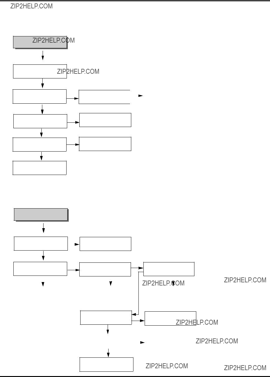
(2) No cassette tape loading
No cassette tape loading
YES
Is there REG. 12V at PMCQ1 Pin8?
YES
Does 'H' signal appear at IC501
Pin62 while inserting CST?
NO
Check power circuit L104.
NO
Is there 5.3V at IC501 Pin73?
Check CST SW and peripheral circuit
Check power circuit
Check D106, L103.
NO
YES
*Caution : Auto stop can occur because Grease or Oil is dried up

SECTION3 ELECTRICAL
ELECTRICAL TROUBLESHOOTING GUIDE
(3) No Key display
No Key display
YES
YES
As pressing the byttons doeseach
function work properly?
NO
Replace bad switches
6. OSD CIRCUIT
(1) No OSD display.
(2) No F.OSD display.
No OSD display.
YES
Is there 5.3V IC501 Pin 51?
YES
NO
NO
Check 5.3V Line of power circuity.
No F.OSD display.
YES
Refer to ???(5) No OSD picture???
YES
NO
NO
Check power Vcc 9V
Does oscillation appear at the
IC501 PIns 37, 38?
Does oscillation appear at the
IC501 Pins 40, 41?
YES
NO
Does Video signal appear at the IC501 Pin 47?
YES
Replace IC501.
Replace X502.
Check peripheral circuit and replace X501
Check the signal between IC501 Pin47 and V.out Jack.
Does video signal appear at IC501 Pin 50?
YES
Replace IC501
Check the signal between IC301 Pin 29 and IC501 Pin 49.
SECTION3 ELECTRICAL
BLOCK & CIRCUIT DIAGRAMS
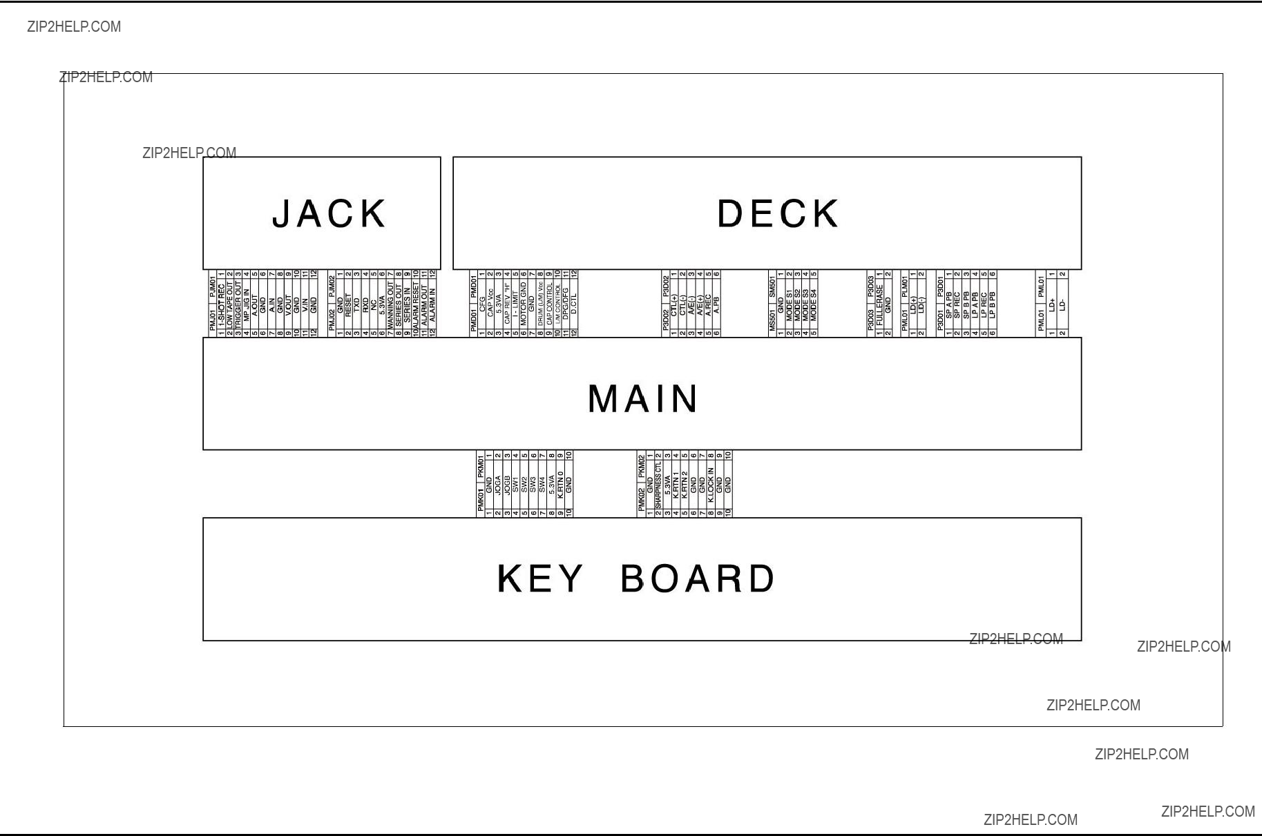
1. OVERALL WIRING DIAGRAM

SECTION3 ELECTRICAL
BLOCK & CIRCUIT DIAGRAMS
2. POWER BLOCK DIAGRAM

SECTION3 ELECTRICAL
BLOCK & CIRCUIT DIAGRAMS
3. POWER CLRCUIT DIAGRAM
SECTION3 ELECTRICAL
BLOCK & CIRCUIT DIAGRAMS
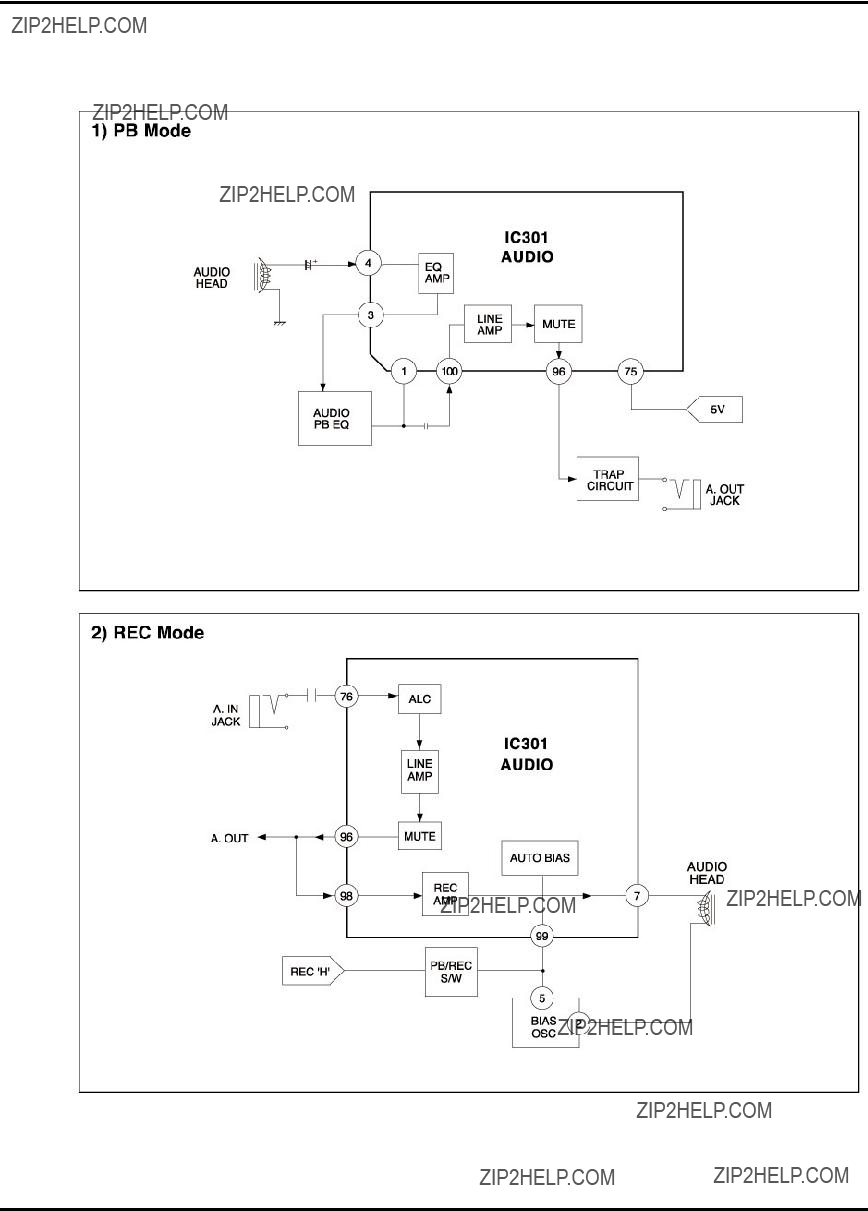
4. AUDIO BLOCK DIAGRAM

SECTION3 ELECTRICAL
BLOCK & CIRCUIT DIAGRAMS
5. Y/C BLOCK DIAGRAM
SECTION3 ELECTRICAL
BLOCK & CIRCUIT DIAGRAMS
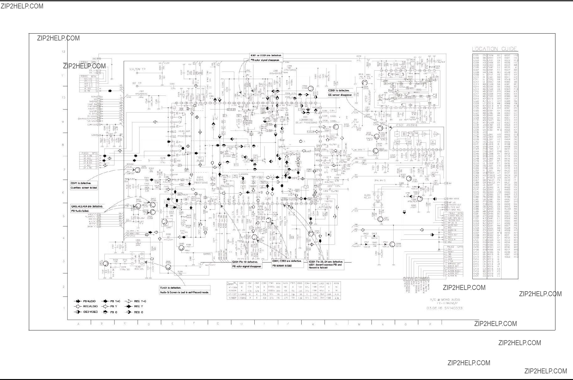
6. A/V CIRCUIT DIAGRAM

SECTION3 ELECTRICAL
BLOCK & CIRCUIT DIAGRAMS
SECTION3 ELECTRICAL
BLOCK & CIRCUIT DIAGRAMS
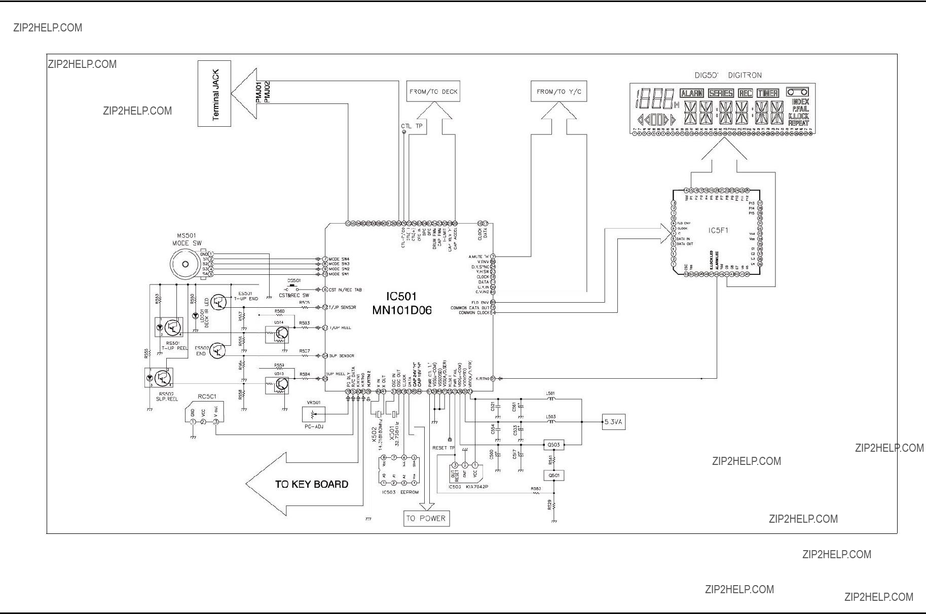
7. SYSTEM BLOCK DIAGRAM
SECTION3 ELECTRICAL
BLOCK & CIRCUIT DIAGRAMS
SECTION3 ELECTRICAL
BLOCK & CIRCUIT DIAGRAMS
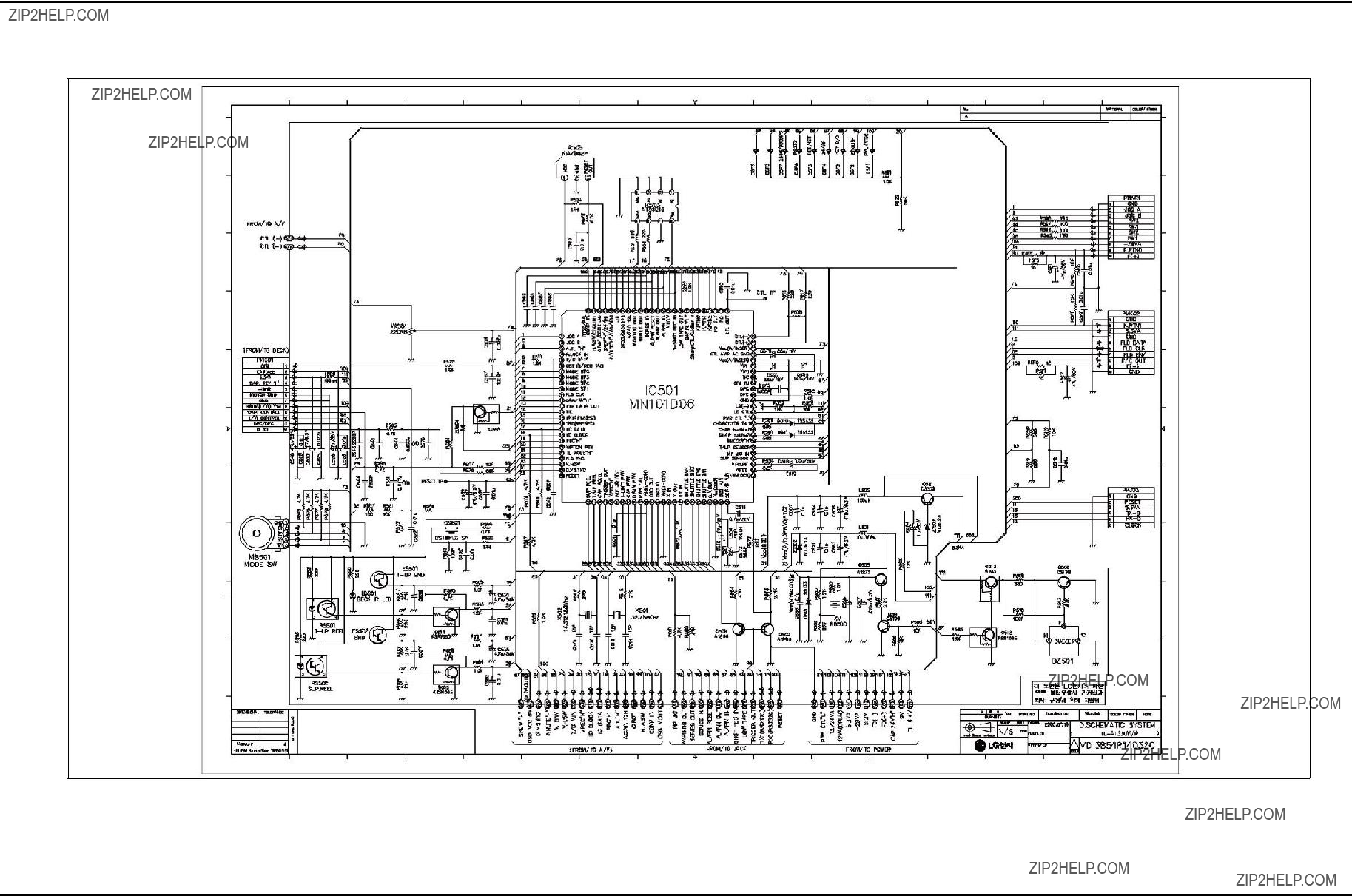
8. SYSTEM CLRCUIT DIAGRAM
SECTION3 ELECTRICAL
BLOCK & CIRCUIT DIAGRAMS
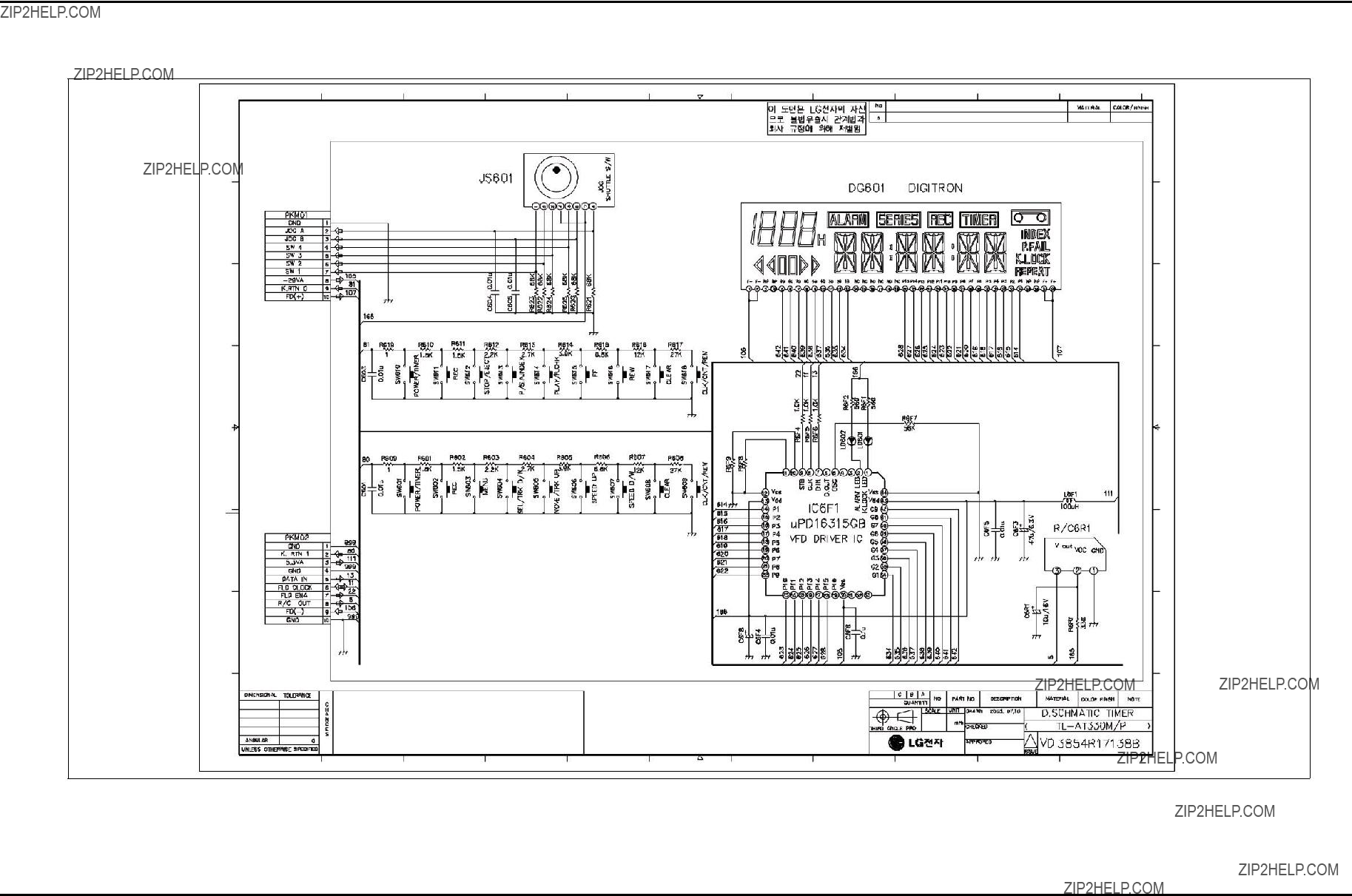
9. JACK CLRCUIT DIAGRAM

SECTION3 ELECTRICAL
BLOCK & CIRCUIT DIAGRAMS
10.
SECTION3 ELECTRICAL
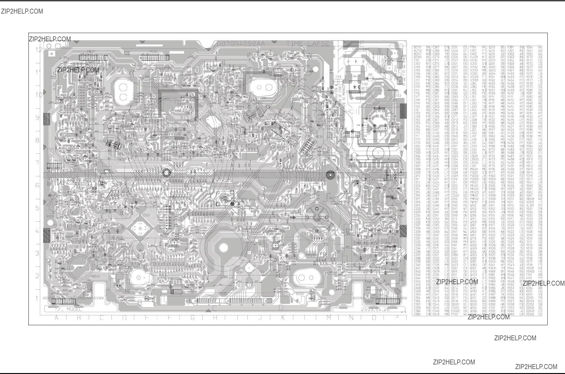
PRINTED CIRCUIT DIAGRAMS
1. MAIN P.C.BOARD
SECTION3 ELECTRICAL
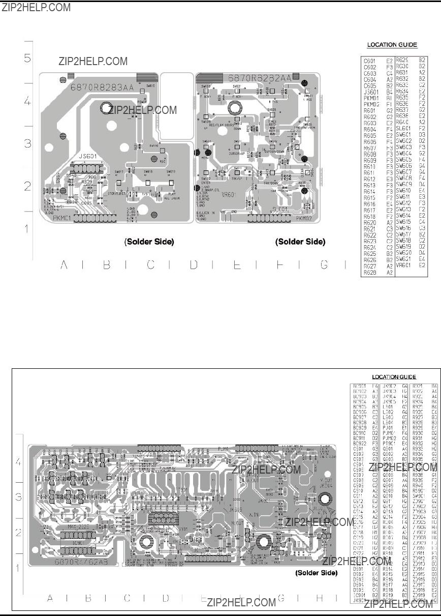
PRINTED CIRCUIT DIAGRAMS
PRINTED CIRCUIT BOARD DIAGRAMS
4. JACK P.C.BOARD
SECTION 4 MECHANISM
CONTENTS
DECK MECHANISM PARTS
LOCATIONS
DECK MECHANISM
DISASSEMBLY
DECK MECHANISM ADJUSTMENT
MAINTENANCE/INSPECTION
PROCEDURE
MECHANISM TROUBLESHOOTING
GUIDE
EXPLODED VIEWS
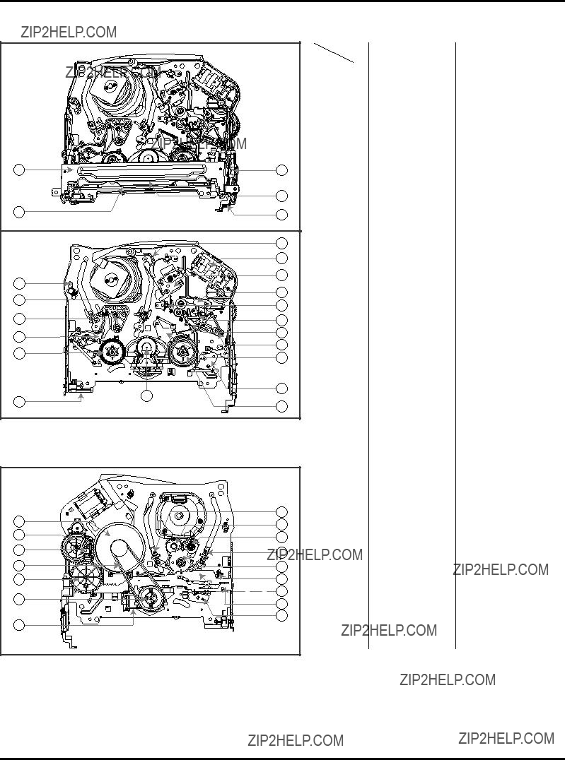
DECK MECHANISM PARTS LOCATIONS
??? Top View
??? Bottom View
NOTE : When reassembly perform the procedure in the reverse order.
1)When reassembling, confirm Mechanism and Mode Switch Alignment Position (Refer to Page
2)When disassembling, the Parts for Starting No. Should be removed first.
T:Top, B:Bottom

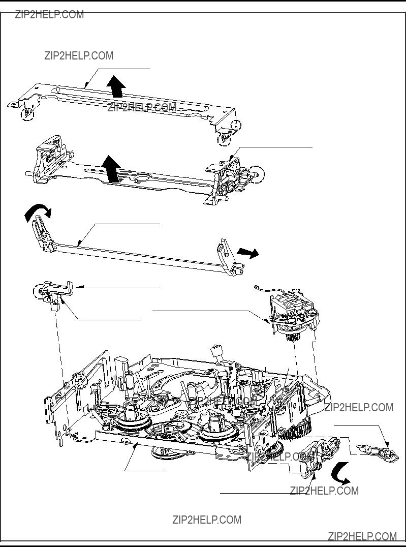
DECK MECHANISM DISASSEMBLY
DECK MECHANISM DISASSEMBLY
DECK MECHANISM DISASSEMBLY
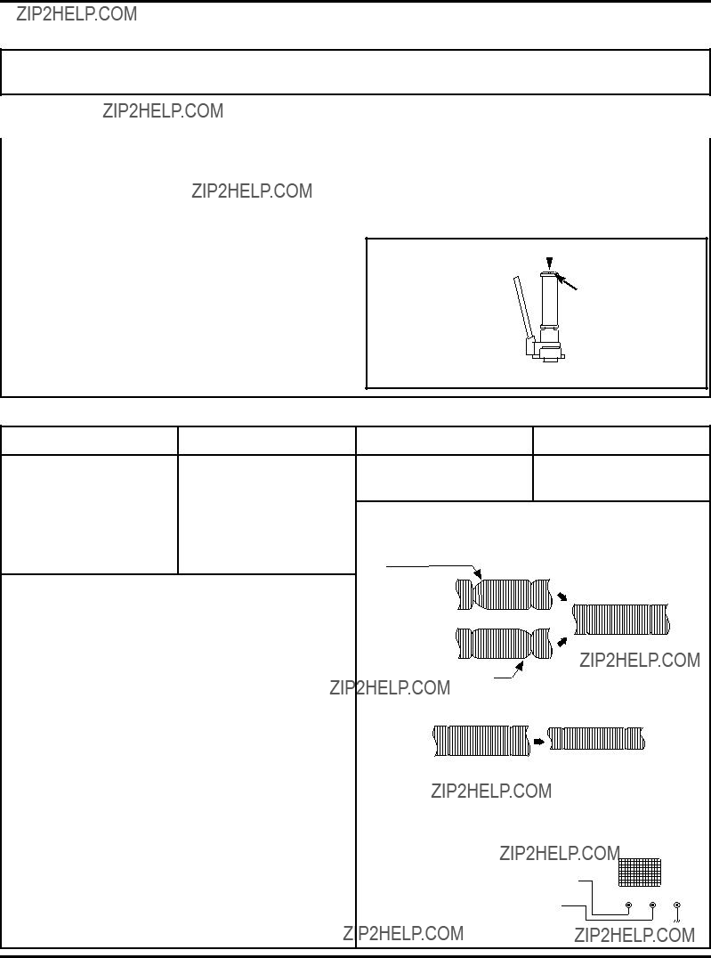
2. Plate Top (Fig.
1)Pull the (B) portion of the Plate Top back in direction of arrow and separate the right side of it.
2)pull the (B???) portion of the Plate Top back in direction of arrow and separate the left side of it.
(Used tools :
NOTE
(1)When reassembling, push the Plate Top after alignment the two position(C), (C???) as below Fig.
2)Unhook three Hooks(H3, H4, H5) on bottom side of the Chassis, lift up the Bracket Assembly L/M and disassem- ble the Bracket Assembly L/D Motor.
(H3)
(H5) 
(B')
(C')
(C)

(B)
6. Gear Assembly Rack F/L (Fig.
1)Move the Gear Assembly Rack F/L in direction of arrow(A) and unhook the Hook(H6) pulling back in front.
2)Separate the Gear Rack F/L in direction of arrow(B).
NOTE
When reassembling, align the gear part of the Gear Assembly Rack F/L with the Gear Drive as below Fig.
3. Holder Assembly CST
1)Move the Holder Assembly CST in direction of arrow and separate the left side of it first through the (D) position of the Chassis.
(D)
2)Disassemble the right side of the Holder Assembly CST from each guided hole of the Chassis.
NOTE
When reassembling, insert the (E) part of the Holder Assembly CST in the (E???) hole of the Chassis first and assemble the left side of it.
4. Opener Door (Figure.
1)Turn the Opener Door clockwise and remove it through the guide hole of the Chassis.
5. Bracket Assembly L/D Motor
(Fig.
1) Unplug the Connector(C1).
Gear Rack F/L
Gear Drive
7. Arm Assembly F/L (Fig.
1)Move the Arm Assembly F/L in direction of arrow and separate the left side of it first.
2)Disassemble the Arm Assembly F/L from each guided hole of the Chassis.
8. Lever Assembly S/W(Fig.
1)Unhook the Hook(H8) in the left side of the Chassis and remove the Lever Assembly S/W.
Chassis
(H8)
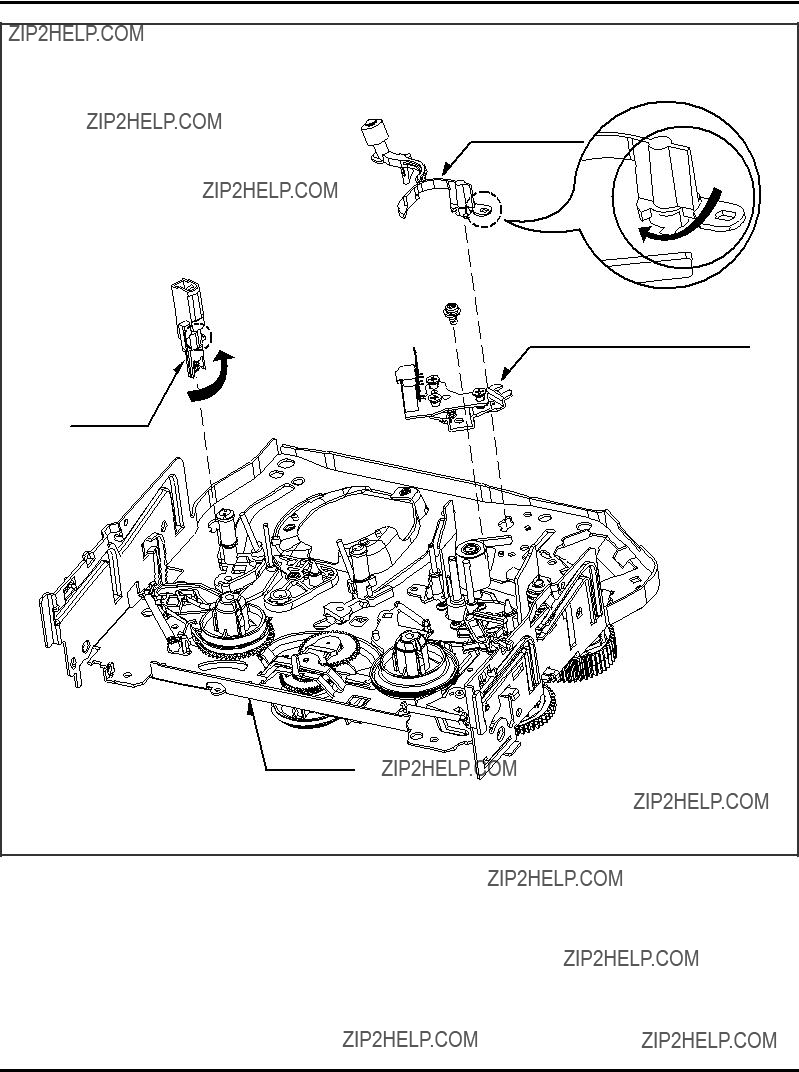
DECK MECHANISM DISASSEMBLY
10. Head F/E (Fig.
1)Breakaway the (A) portion of the Head F/E from the embossing of the Chassis, turn it to counterclockwise direction and lift it up.

DECK MECHANISM DISASSEMBLY
1)Unhook the Spring TB from the Hook(H9) of the Chassis.
2)Lift the Brake Assembly T up.
13. Brake Assembly RS (Fig.
1)Unhook the Spring RS from the Hook(H10) of the Chassis.
2)Lift the Brake Assembly T up.
14. Arm Assembly Tension (Fig.
Difference for Springs
Spring TB
Spring RS Color (Black)
Spring Tension
15. Reel S / Reel T (Fig.
1) Difference for Reel S / Reel T
1)Unhook the Spring Tension from the Hook(H11) of the Arm Assembly Tension.
2)Unhook the Hook(H12) of the Base Tension and lift the Arm Assembly Tension up.
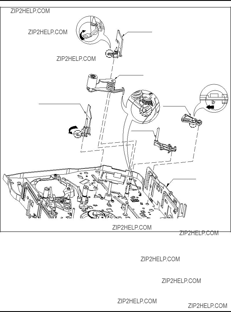
DECK MECHANISM DISASSEMBLY
1)Breakaway the (A) portion of the Base Assembly P4 from the embossing of the Chassis.
2)Turn the Base Assembly P4 to counterclockwise direction and lift it up.
When reassembling, confirm the (C) portion of the Arm Assembly Pinch is inserted to the Chassis hole correctly as Fig.
17. Opener Lid (Fig.
1)Breakaway the (B) portion of the Opener Lid from the embossing of the Chassis.
2)Turn the Opener Lid to clockwise direction and lift it up.
19. Lever T/up (Fig.
Arm T/up (Fig.
1)Unhook the Hook(H13) of the bottom Chassis and lift the Lever T/up up.
2)Lift the Arm T/up up.
18. Arm Assembly Pinch (Fig.
1) Lift the Arm Assembly Pinch up.

DECK MECHANISM DISASSEMBLY
21. Lever F/R (Fig.
1)Unlock the Locking Tab(L1) as Fig.
1)Pull the Locking Tab(L2) back in direction of arrow and lift it up.
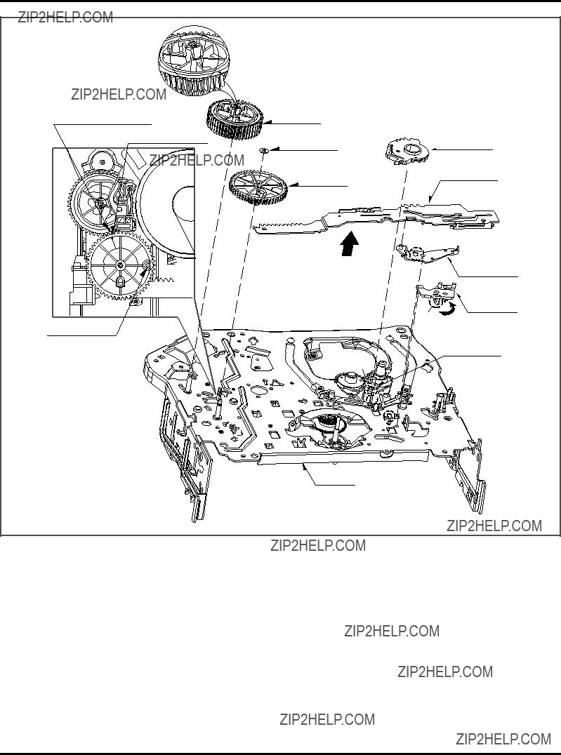
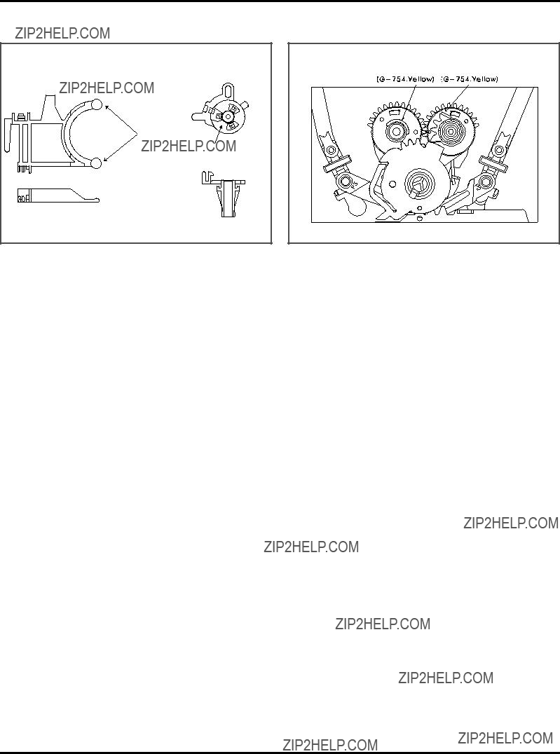
DECK MECHANISM DISASSEMBLY
1)Remove the Washer(W2) and lift the Gear Drive up.
2)Unhook the Hook(H14) of the Gear Cam and lift the Gear Cam up.
NOTE
When reassembling, align the Gear Drive Hole(A) and the Gear Cam Hole(B) in a straight line after the Gear Drive Hole(C) is aligned with the Chassis Hole as Fig.
25. Gear Sector (Fig.
1)Unhook the Hook(H15) of the Base Loading on bottom Chassis and lift the Gear Sector up.
27. Lever Tension (Fig.
1)Unhook the (A) portion of the Lever Tension from the Hook(H16) of the Chassis.
2)Turn the Lever Tension to counterclockwise direction and lift it up.
28. Lever Spring (Fig.
1)Unlock the Locking Tab(L3) of the bottom Chassis and lift the Lever Spring up.

DECK MECHANISM DISASSEMBLY
29.Gear Assembly P2 (Fig.
1)Just lift the Gear Assembly P2 up.
2)Just lift the Gear Assembly P3 up.
NOTE
When reassembling, align the two holes of the Gear Assembly P2 and P3 in a straight line after confirmation whether the Gear Sector Hole(A) and the Plate Slider Hole(B) are aligned or not as Fig.
30. Base Assembly P2 (Fig.
1)Move the Base Assembly P2 in direction of arrow(A) along the guide hole of the Chassis and disassemble it on bottom side.
2)Move the Base Assembly P3 in direction of arrow(B) along the guide hole of the Chassis and disassemble it on bottom side.
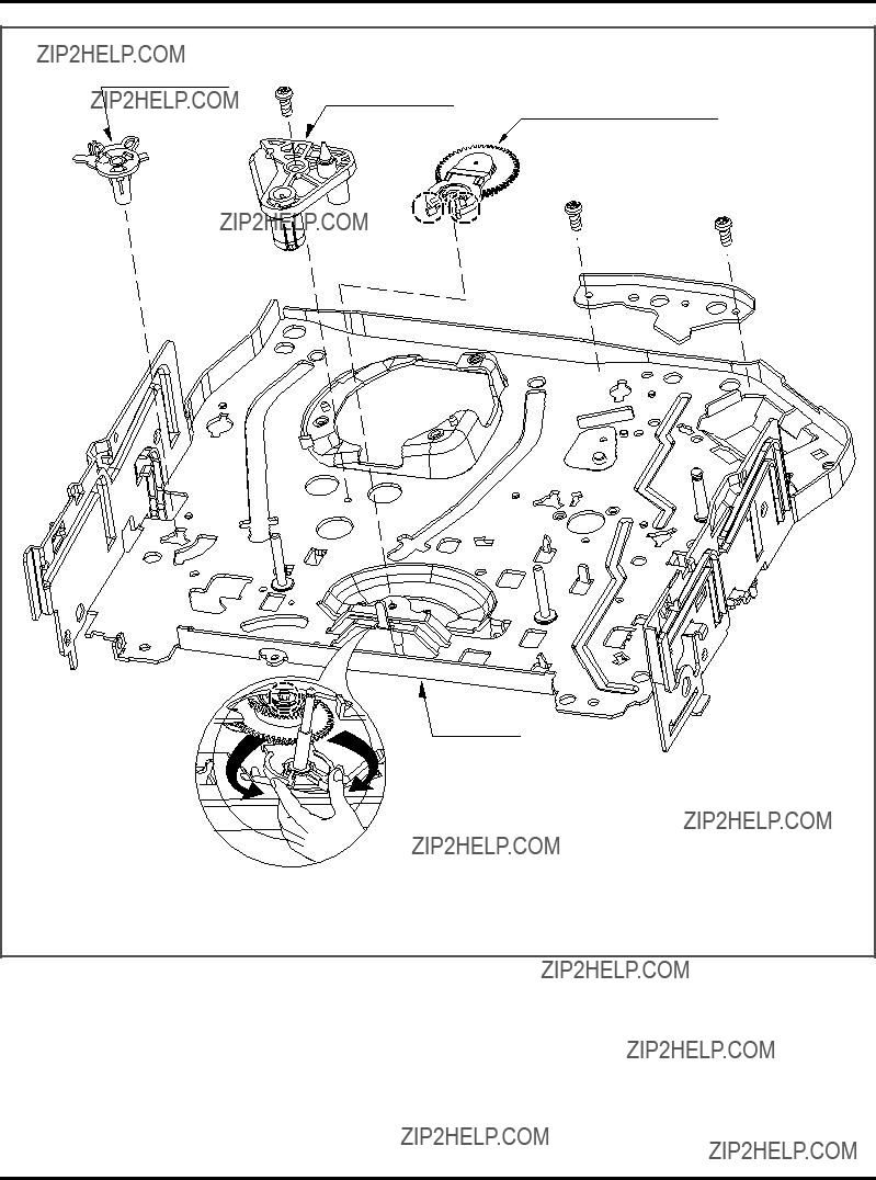
DECK MECHANISM DISASSEMBLY
32. Base Tension (Fig.
1)Breakaway the (A) portion of the Base Tension from the embossing of the Chassis.
2)Turn the Base Tension to counterclockwise direction and lift it up.
NOTE
When disassembling, be careful not to be caught the (D) part by the Chassis as Fig.

DECK MECHANISM ADJUSTMENT
??? Tools and Fixfures for Service
S
R
250
DECK MECHANISM ADJUSTMENT
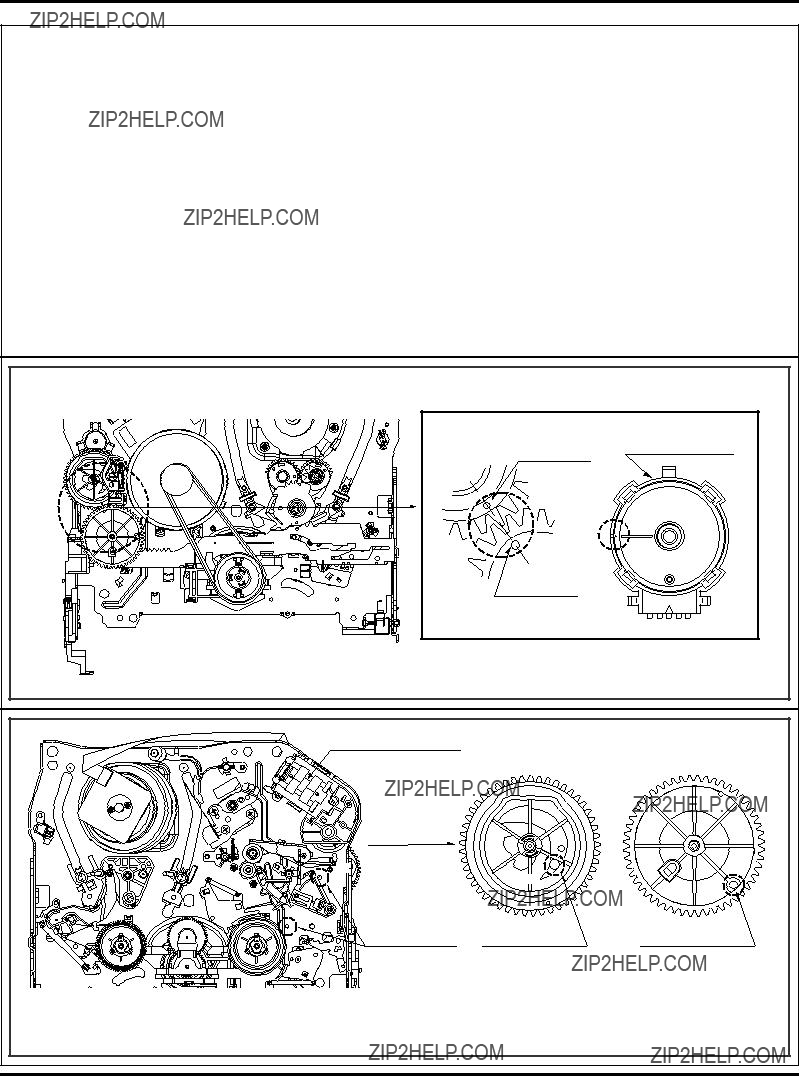
1. Mechanism Alignment Position Check
Purpose:To determine if the Mechanism is in the correct position, when a Tape is ejected.
1)Turn the Power S/W on and eject the Cassette by press- ing the Eject Button.
2)Remove the Top Cover and Plate Assembly Top, visual- ly check if the Gear Cam Hole is aligned with the Chassis Hole as below Fig.
3)IF not, rotate the Shaft of the Loading Motor to either clockwise or counterclockwise until the alignment is as below Fig.
4)Remove the Screw which fixes the Deck Mechanism and Main Frame and confirm if the Gear Cam is aligned with the Gear Drive as below Fig.
5)Confirm if the Mode S/W on the Main P.C.Board is aligned as below Fig.
6)Remount the Deck Mechanism on the Main P.C.Board and check each operation.
CHECK DIAGRAM
Gear Cam
Mode S/W
(B)
(A)
Gear Drive
Gear Cam (o) and Gear Drive (o) groove alignment
BOTTOM VIEW
Fig.
L/D Motor Assembly
Gear Cam
TOP VIEW
Fig.
DECK MECHANISM ADJUSTMENT
2.Preparation for Adjustment (To set the Deck Mechanism of the loading state
without inserting a cassette tape).
1)Unplug the power cord from the AC outlet.
2)Disassemble the Top Cover and Plate Assembly Top.
3)Plug the power cord into the AC outlet.
4)Turn the power S/W on and push the Lever Stopper of the Holder Assembly CST to the back for loading the
cassette without tape.
Cover the holes of the End Sensors at the both sides of the Chassis to prevent a light leak.
Then the Deck Mechanism drives to the Stop Mode. In this case, the Deck Mechanism can accept inputs of each mode, however the Rewind and Review operation can not be performed for more than a few seconds because the
3. Checking Torque
Purpose: To insure smooth transport of the tape during each mode of operation.
If the tape transport is abnormal, then check the torque as indicated by the chart below.
The values are measured by using a Torque Gauge and Torque Gauge Adaptor with the Torque Gauge affixed.
The torque reading to measure occurs when the tape abruptly changes direction from Fast Forward to Rewind Mode, when quick braking is applied to both Reels.
 Torque Gauge
 Torque Gauge
Adaptor

 Reel Table
S
R
T- H
S
DECK MECHANISM ADJUSTMENT
4.Guide Roller Height Adjustment
Purpose: To regulate the height of the tape so that the bottom of the tape runs along the tape guide line on the Lower Drum.
Adjustment Procedure
1)Confirm if the tape runs along the tape guide line of the Lower Drum.
2)If the tape runs the bottom of the guide line, turn the Guide Roller Height Adjustment Screw to clockwise direction.
3)If it runs the top, turn to counterclockwise direction.
4)Adjust the height of the Guide Roller to be guided to the guide line of the Lower Drum from the starting and end- ing point of the Drum.
ADJUSTMENT DIAGRAM  Guide Roller Height
Adjustment screw
Upper Flange

 Guide Roller
Retaining Screw
Fig.
Adjustment Procedure
1)Play an Alignment Tape after connecting the probe of the Oscilloscope to the RF Envelope Output Test Point and
3)Height Adjustment Screw : Flatten the RF waveform. (Fig.
4)Turn(Move) the Tracking Control(in PB Mode) clockwise

DECK MECHANISM ADJUSTMENT
5. Audio/Control (A/C) Head Adjustment
Purpose: To insure that the tape passes accurately over the Audio and Control Tracks in exact alignment of the both Record and Playback Modes.
Perform the Preliminary Adjustment, when there is no Audio Output Signal with the Alignment Tape.
Adjustment Procedure/Diagrams
1)Initially adjust the Base Assembly A/C Head as shown Fig.
2)Play a blank tape and observe if the tape passes accu- rately over the A/C Head without tape curling or folding.
3)If folding or curling is occured then adjust the Tilt Adjustment Screw(C) while the tape is running to resem- ble Fig.
4)Reconfirm the tape path after Playback about 4~5 sec- onds.
NOTE
Ideal A/C head height occurs when the tape runs between 0.2~0.25mm above the bottom edge of the A/C Head core.

DECK MECHANISM ADJUSTMENT
1)After completing Step
(1)If folding or curling is observed at the bottom of the
(2)If folding or curling is observed at the top of it then slowly turn the Tilt Adjustment Screw(C) in the counterclockwise direction.
NOTE:
Check the RF envelope after adjusting the A/C Head, if the RF waveform differs from Fig.
Adjustment Procedure
1)Connect the probe of the oscilloscope to Audio Output Jack.
2)Alternately adjust the Azimuth Adjustment Screw(A) and the Tilt Adjustment Screw(C) for maximum output of the 1KHz and 7KHz segments, while maintaining the flattest envelope differential between the two frequencies.
Fig.
6.
Purpose: To obtain compatibility with the other VCR(VCP) Models.

DECK MECHANISM ADJUSTMENT
7. Adjustment after Replacing Drum Assembly (Video Heads)
Purpose: To correct for shift in the Roller Guide and X value after replacing the Drum.
Fig.
8. Check the Tape Travel after Reassembling Deck Assembly.
Checking Procedure
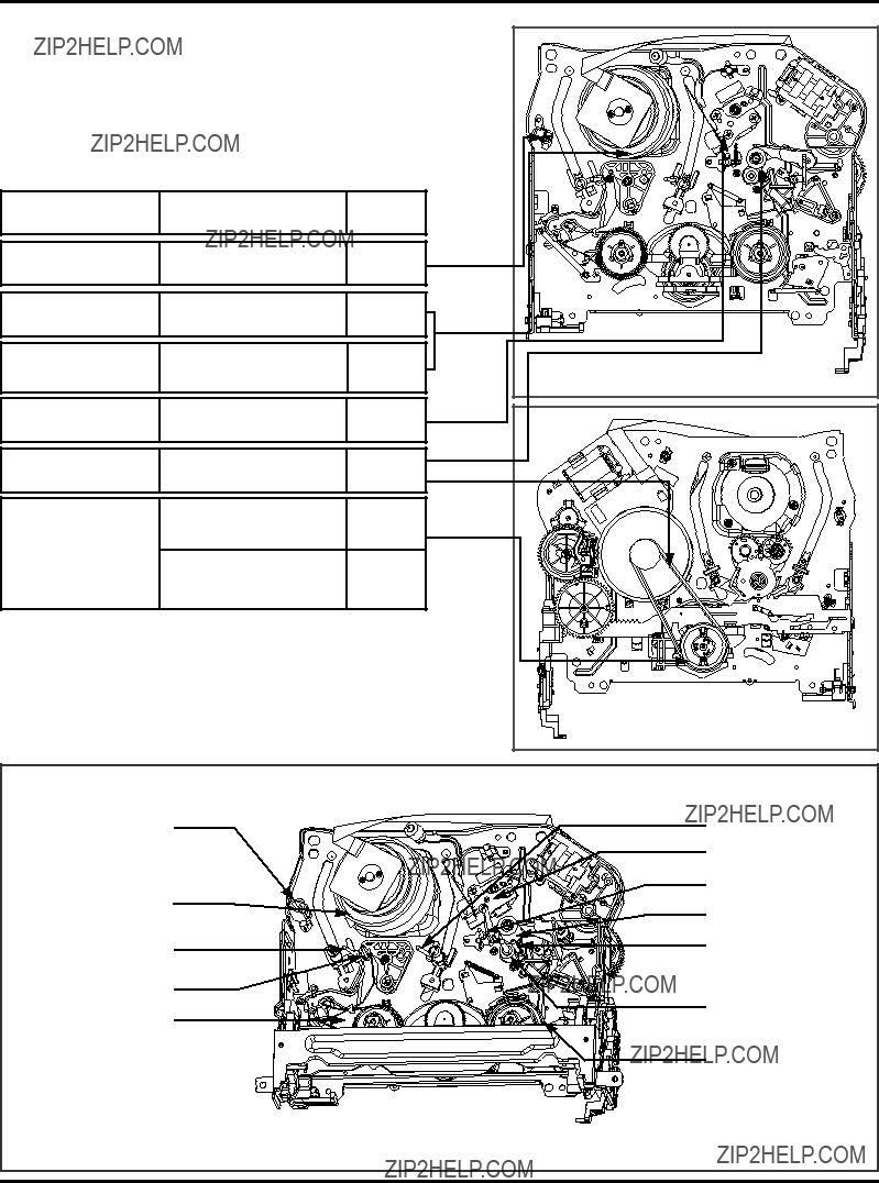
Fig.

MAINTENANCE/INSPECTION PROCEDURE
2. Required Maintenance
The recording density of a VCR(VCP) is much higher than that of an audio tape recorder. VCR(VCP) components must be very precise, at tolerances of 1/1000mm, to ensure com- patibility with the other VCRs. If any of these components are worn or dirty, the symptoms will be the same as if the part is defective. To ensure a good picture, periodic inspection and maintenance, including replacement of worn out parts and lubrication, is necessary.
3. Scheduled Maintenance
Schedules for maintenance and inspection are not fixed because they vary greatly according to the way in which the customer uses the VCR(VCP), and the environment in which the VCR(VCP) is used.
But, in general home use, a good picture will be maintained if inspection and maintenance is made every 1,000 hours. The table below shows the relation between time used and inspection period.
Table 1
Two hours
Three hours
4.Supplies Required for Inspection and Maintence
(1)Grease : Kanto
(2)Isopropyl Alcohol or equivalent
(3)Cleaning Patches
(4)Grease : Kanto
5. Maintenance Procedure
(1)Cleaning video head
First use a cleaning tape. If the dirt on the head is too stubborn to remove by tape, use the cleaning patch. Coat the cleaning patch with Isopropyl Alcohol. Touch the cleaning patch to the head tip and gently turn the head(rotating cylinder) right and left.
(Do not move the cleaning patch vertically. Make sure that only the buckskin on the cleaning patch comes into contact with the head. Otherwise, the head may be dam- aged.)
Thoroughly dry the head. Then run the test tape. If lso- propyl Alcohol remains on the video head, the tape may be damaged when it comes into contact with the head surface.
(2)Clean the tape transport system and drive system, etc, by wiping with a cleaning patch wetted with Isopropyl Alcohol.
NOTES:
1It is the tape transport system which comes into contact with the running tape. The drive system consists of those parts which moves the tape.
2Make sure that during cleaning you do not touch the tape transport system with excessive force that would cause deformation or damage to the system.
Drum
(Rotating Cylinder)
Cleaning Patch
Head Tip
Touch this section of cleaning Coat With Isopropyl Alcohol patch to the head tip and gently
turn the Drum (Rotating Cylinder)
Fig.
MAINTENANCE/INSPECTION PROCEDURE
Chassis (Bottom)
MAINTENANCE/INSPECTION PROCEDURE
Lever, F/R, Base, Tension

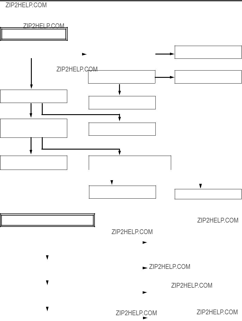
MECHANISM TROUBLESHOOTING GUIDE
1.Deck Mechanism
A.
Auto REW doesn't work.
YES
YES
Check the syscon circuit.
B.
No F/R modes.
YES
Check the syscon power.
YES
Do the T/Up, Supply Reel rotate?
YES
Check the syscon circuit.
YES
Check the servo, power circuits.
MECHANISM TROUBLESHOOTING GUIDE
C.
AUTO STOP. (PLAY/CUE/REV)
In Play/Cue/Rev, Is the Pinch Roller in contact with the Capstan Shaft?
YES
Are there T/up and Supply Reel pulses.
YES
Check the Syscon,
D.
Cassette doesn???t load.
Check alignment positions (page
NO
NO
YES
NO
Check the Servo, Syscon.
Replace the Reel Sensor.
Insert the cassette.
YES

MECHANISM TROUBLESHOOTING GUIDE
E.
In PB mode Tape Presence not sensed.
NO
Is the Pinch Roller attached to the Capstan Motor Shaft?
Check Alignment positions (page
Does the Capstan Motor turn?
YES
NO
Does the Drum Motor turn?
YES
Are there DPG, DFG pulses?
YES
Are the T/Up and Supply Reel
Sensors ok?
YES
NO
Check the Clutch and Idler
Assembly.
Is the voltage supplied to the
Capstan Motor Vcc1,Vcc2 each?
YES
YES
Replace the Capstan Motor.
NO
Is the Vcc voltage of the Drum
Check the Servo, Syscon.
Motor normal?
YES
Check the Syscon, Circuit.
YES
Replace the
Drum Motor.
MECHANISM TROUBLESHOOTING GUIDE
2. Front Loading Mechanism
A.
Cassette cannot be inserted.
YES 
YESDoes the CST IN Switch work normally?
YES
Is the Vcc of Main P.C.Board
5V?
Check the syscon circuit.
YES NO
Is the voltage between cassette
switch and GND on MainCheck the power circuit. P.C.Board 5V??
YES NO
NO
NO
Replace or add the Lever Assembly Switch Spring.
Replace the CST IN Switch.
Check the Mode switch location and syscon circuit.
B.
Is there a short circuit between cassette switch and GND on main P.C.Board?
Cassette does not eject.

MECHANISM TROUBLESHOOTING GUIDE
C.
Cassette does not load.
Does the cassette insert?
YES
Does the Opener Lid work?
YES NO
Does the Gear Assembly Rack F/L work?
Replace the Opener Lid.
YES
NO
Does the Opener Door work?
YES NO
Does the Arm Assembly F/L work?
YES NO
Does the L/D Motor work?
YES NO
Does the Holder Assembly Cassette move the Arm Assembly F/L?
YES NO
Replace the Front Loading
Mechanism Assembly.
Replace the Gear Rack F/L.
Check the opener Door assembled correctly.
Replace the Arm Assembly F/L.
Check the power of L/D Motor.
Check the Holder Assembly Cassette assembled correctly.
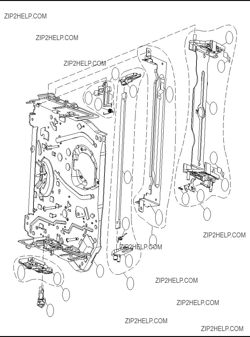
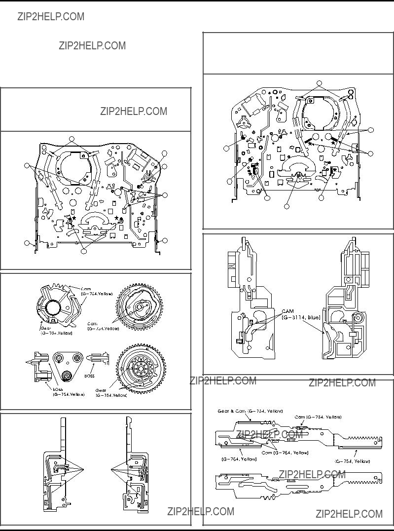
EXPLODED VIEWS
1. Front Loading Mechanism Section
OPTIONAL PART
401
402
002A
022
011
079
032
402008
002
004
003
405
023
012
019
018
028
021
020
024
406
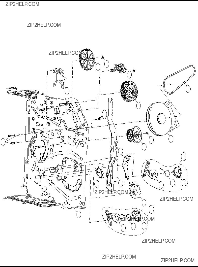
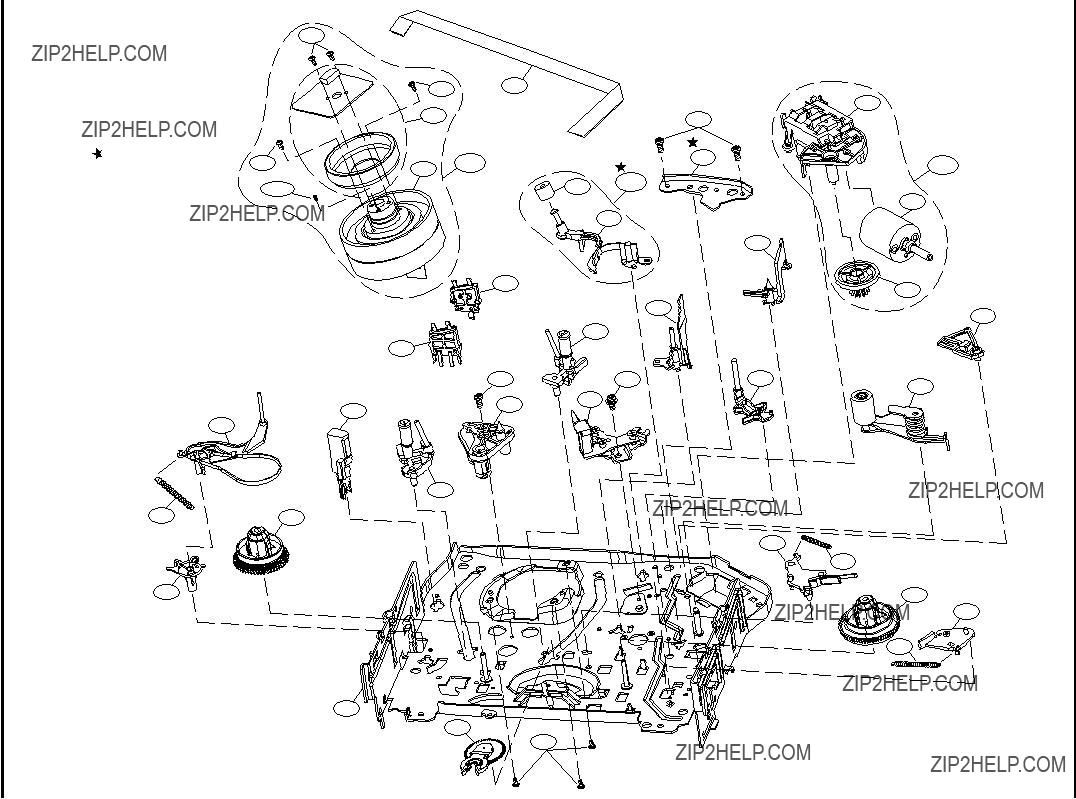
EXPLODED VIEWS
3. Moving Mechanism Section(2)
 OPTIONAL PART

SECTION 5. REPLACEMENT PARTS LIST
NOTE: Warning
Parts that are shaded are critical With respect to risk of fire or electrical shock.
-

Cabinet & Main Frame Section
PARTS SECTION
Packing & Accessory Section
-
-
-
-

-

-
-
-
-
-

-
-