Failure to use LHP parts or conduct variations in techniques and construction materials described in this installation manual may create a serious fire hazard and may void the warranty and the WHI listing.
3.Always check your local building codes. The installation must comply with their regulations. Before beginning the instal- lation, consult the local authorities and make sure your building permit complies with their requirements.
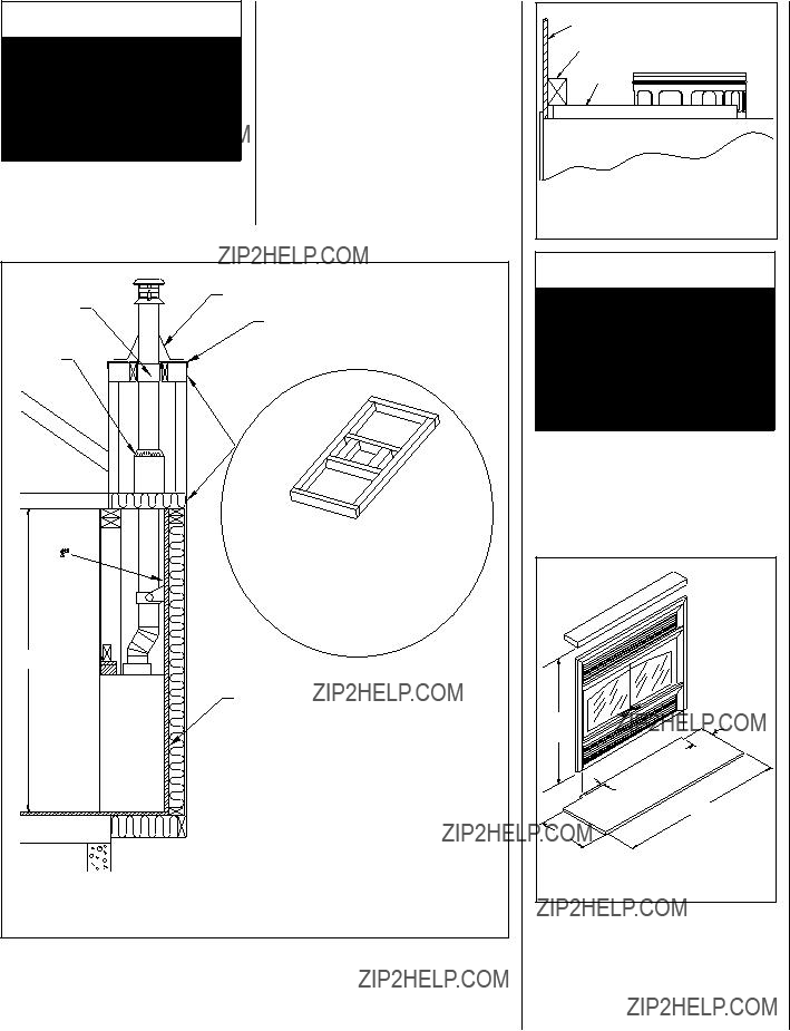
4.This fireplace must be installed with Security
Chimneys??? chimney system models ASHT+, S-2100+ or AC, of 8" inside diameter. These systems are intended for use in any applica- tionwhereatraditionalmasonrytypefireplace would apply. The chimney system must always vent to the outside of the building.
5.To maintain top efficiency and to prevent build-up of soot and creosote, inspect and clean the chimney periodically during the heating season.
6.To prevent possible hazards due to poor combustion and to avoid affecting other fuel burning appliances (furnace, wood stove, etc.), ensure that the outside air kit is properly installed.
7.This fireplace is designed to allow the instal- lation of a gas burner. In such a case, the installation must conform with the National Gas Code ANSI Z223.1 and Z21.60.
 WARNING
When using a gas burner, it is mandatory to keep the chimney outside air register opened.
8.This fireplace has provision for the installa- tion of a gas pipe and is intended only for connection to a decorative gas appliance incorporating an automatic shutoff device and complying with ANSI Z21.60-M96/CGA 2.26-M96, Standard for Decorative Gas Ap- pliances for Installation in Solid-Fuel Burning Fireplaces (reference Clause 4.1.3 T).
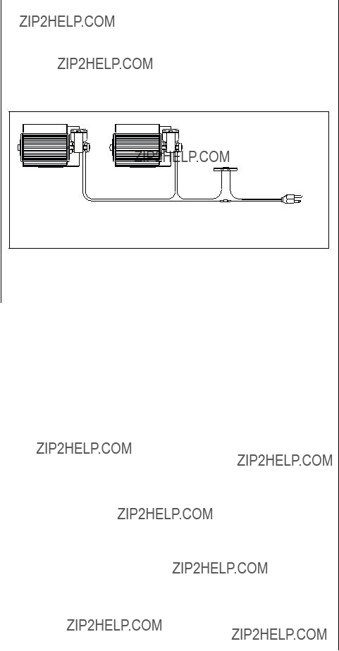
9.The ME43 fireplaces are sold with factory installed doors. The outside combustion air kit is mandatory and is included with the fireplace. Optional blowers and decorative trims are available.
Tools And Building Supplies Normally
Required
Tools:
Phillips screwdriver
Slot style screwdriver
Hammer
Saw and/or Sabersaw
Level
Measuring tape
Plumb line
Electric drill and bits
Pliers
Square
If gas pipe is used:
Pipe wrench
Pipe cutter
Pipe threader
Pipe joint compound
Pipe key valve
Building supplies:
2" x 3" or heavier lumber Drywall panel or equivalent
Silicone caulking (non-combustible) Overlay material for fireplace fa??ade Hearth extension (non-combustible)
precautions!
The most important areas of concern dealing with the fireplace installation are clearances to combustible materials, secure assembly of components parts, the height of the chimney system, the proper use of accessory equip- ment and the techniques used in using finish- ing materials applied to fireplace surrounds, hearth extensions and wall coverings. Each of these topics will be covered in greater detail throughout this manual. Please give special attention to these instructions as you progress with your installation.
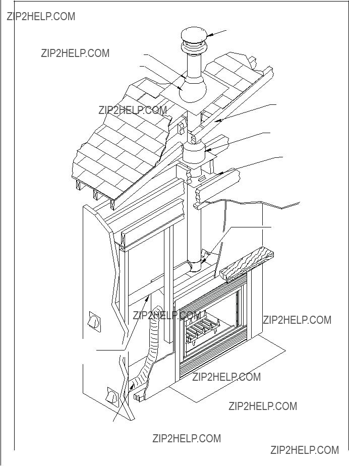
Fireplace Installation Procedure
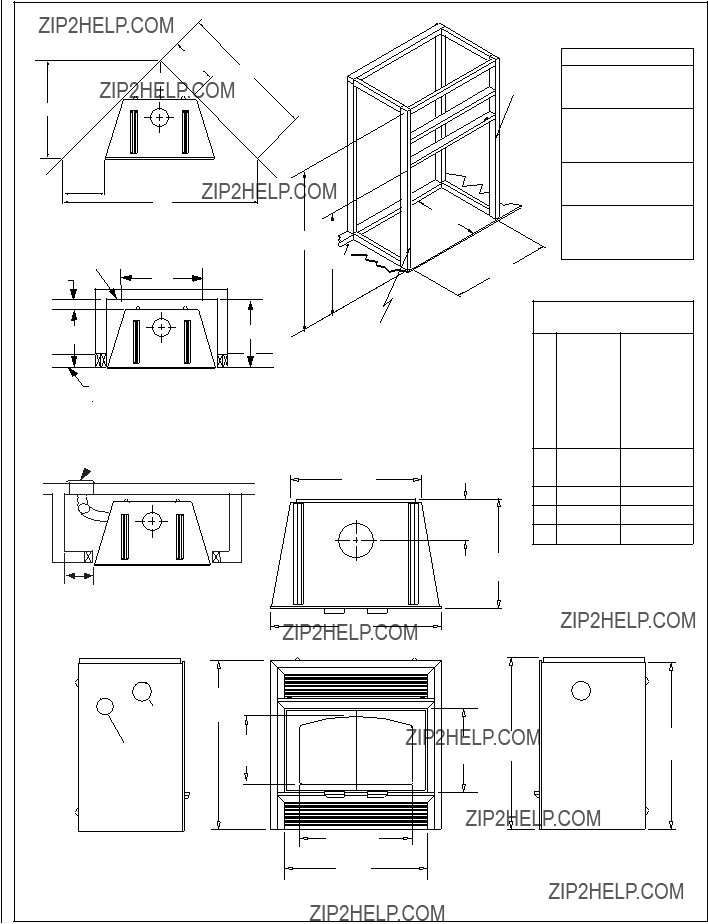
1.Move the fireplace into the desired position (follow the recommendations below for enclosure).
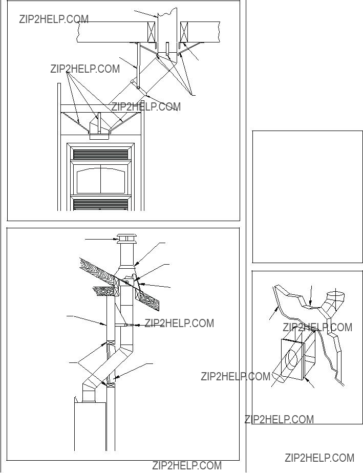
2.Install the outside air assembly (or assem- blies) - refer to Page 8.
3.Install the enclosure surrounding the fire- place (refer to the sections ???Enclosure??? below and ??? Facing and Mantel??? on Page 7).
4.Install the hearth extension (see Page 8). Make sure the gap between the fireplace and the hearth extension is sealed.
NOTE: DIAGRAMS & ILLUSTRATIONS ARE NOT TO SCALE.
Locating the LENNOX Fireplace
Do not place the fireplace on carpeting, vinyl or other soft surface floor coverings. It may, however, be directly placed on flat wood, plywood, particle board or other hard surface materials.
Adjacent wall
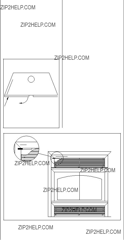
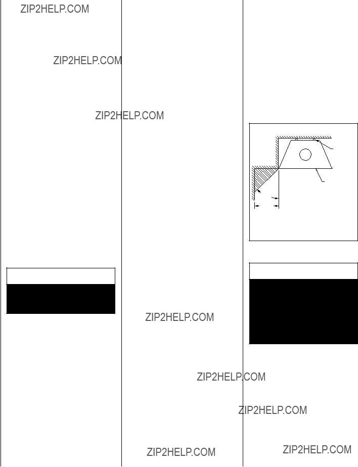
A wall perpendicular to and in front of the fire- place front facing must be at least 18" (460mm) from the fireplace opening. A wall at 45?? to the front facing and starting at the fireplace???s outer edge is permitted. Projections within this area are permitted. See Figure 4.
 WARNING
Do not place loose insulation or any other material in the space around the fireplace or the chimney. Insulation placed on or around the fireplace or chim- ney may cause adjacent wood to overheat and catch on fire.
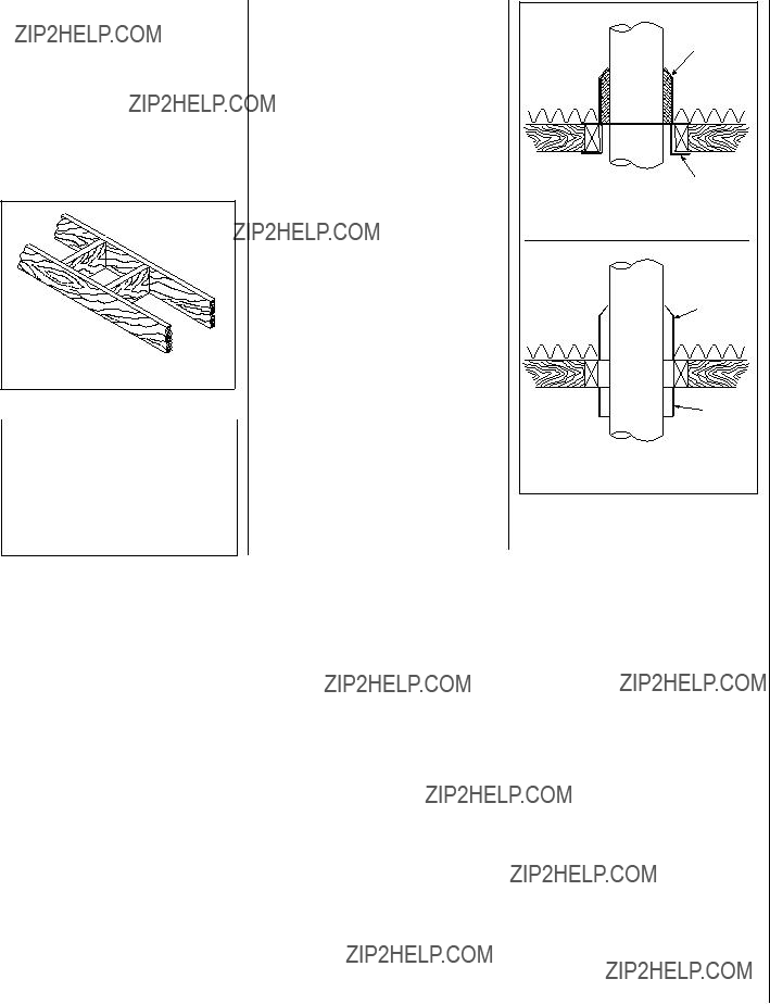
1.The fireplace must be installed against a finished wall (like drywall finish). It must not be installed against a vapor barrier or exposed insulation (see Figure 5).
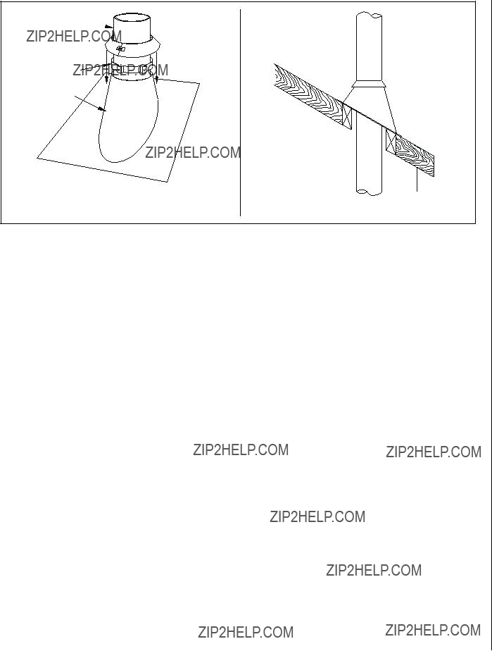
2.Combustible materials like wood, plywood, particle board or drywall can be in direct contact with the fireplace standoffs. Two inch (50mm) clearance to combustibles must be kept around the chimney.
 WARNINGS
 WARNINGS
 WARNING
 IMPORTANT
 WARNING
 CAUTION
 WARNING
 WARNING
 CAUTION
 WARNING
 WARNING
 WARNING
 WARNING
 WARNING
 WARNING
 WARNING
 CAUTION
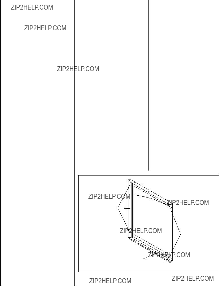
 WARNING
 WARNING
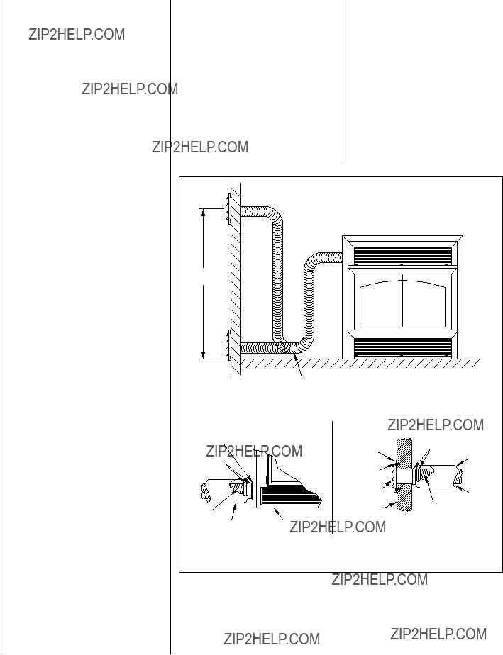
 MIN.
MIN. Air Kit
 WARNING
 WARNING