CANADA : http//biz.lgservice.com
USA : http//www.lgservice.com
: http//lgservice.com/techsup.html
COLOR TV
SERVICE MANUAL
CHASSIS :
MODEL : 30FZ4D
MODEL :
CAUTION
BEFORE SERVICING THE CHASSIS,
READ THE SAFETY PRECAUTIONS IN THIS MANUAL.
CANADA : http//biz.lgservice.com
USA : http//www.lgservice.com
: http//lgservice.com/techsup.html
COLOR TV
SERVICE MANUAL
CHASSIS :
MODEL : 30FZ4D
MODEL :
CAUTION
BEFORE SERVICING THE CHASSIS,
READ THE SAFETY PRECAUTIONS IN THIS MANUAL.
SAFETY PRECAUTIONS
IMPORTANT SAFETY NOTICE
Many electrical and mechanical parts in this chassis have special  in the Schematic Diagram and Replacement Parts List.
It is essential that these special safety parts should be replaced with the same components as recommended in this manual to prevent
Do not modify the original design without permission of manufacturer.
General Guidance
An lsolation Transformer should always be used during the servicing of a receiver whose chassis is not isolated from the AC power line. Use a transformer of adequate power rating as this protects the technician from accidents resulting in personal injury from electrical shocks.
It will also protect the receiver and it's components from being damaged by accidental shorts of the circuitary that may be inadvertently introduced during the service operation.
If any fuse (or Fusible Resistor) in this TV receiver is blown, replace it with the specified.
When replacing a high wattage resistor (Oxide Metal Film Resistor, over 1W), keep the resistor 10mm away from PCB.
Keep wires away from high voltage or high temperature parts.
Due to high vacuum and large surface area of picture tube, extreme care should be used in handling the Picture Tube. Do not lift the Picture tube by it's Neck.
Warning:
The source of
For continued
To determine the presence of high voltage, use an accurate high impedance HV meter.
Adjust brightness, color, contrast controls to minimum. Measure the high voltage.
The meter reading should indicate
23.5 !1.5KV:
29.0!1.5KV:
If the meter indication is out of tolerance, immediate service and correction is required to prevent the possibility of premature component failure.
Before returning the receiver to the customer,
always perform an AC leakage current check on the exposed metallic parts of the cabinet, such as antennas, terminals, etc., to be sure the set is safe to operate without damage of electrical shock.
Leakage Current Cold Check(Antenna Cold Check)
With the instrument AC plug removed from AC source, connect an electrical jumper across the two AC plug prongs. Place the AC switch in the on positioin, connect one lead of
If the exposed metallic part has a return path to the chassis, the measured resistance should be between 1M??? and 5.2M???. When the exposed metal has no return path to the chassis the reading must be infinite.
An other abnormality exists that must be corrected before the receiver is returned to the customer.
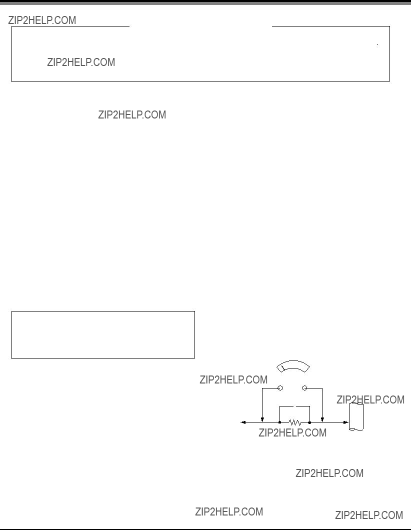
Leakage Current Hot Check (See below Figure) Plug the AC cord directly into the AC outlet.
Do not use a line Isolation Transformer during this check.
Connect 1.5K/10watt resistor in parallel with a 0.15uF capacitor between a known good earth ground (Water Pipe, Conduit, etc.) and the exposed metallic parts.
Measure the AC voltage across the resistor using AC voltmeter with 1000 ohms/volt or more sensitivity.
Reverse plug the AC cord into the AC outlet and repeat AC voltage measurements for each esposed metallic part. Any voltage measured must not exceed 0.75 volt RMS which is corresponds to 0.5mA.
In case any measurement is out of the limits sepcified, there is possibility of shock hazard and the set must be checked and repaired before it is returned to the customer.
Leakage Current Hot Check circuit
AC
1.5 Kohm/10W
CANADA: LG Electronics Canada, Inc. 550 Matheson Boulevard East Mississauga, Ontario L4Z 4G3
- 2 -

- 3 -
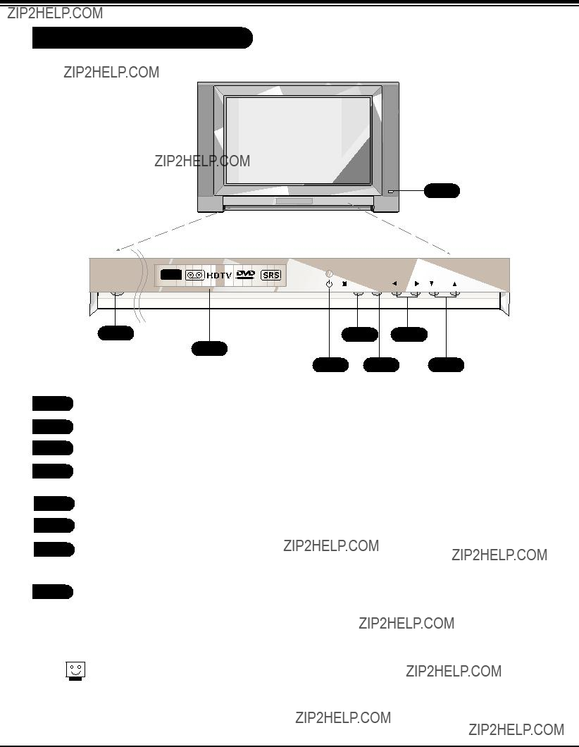
DESCRIPTION OF CONTROLS
Front Panel Controls
3
2
4 6 8
5 TV/VIDEO
6MENU
7VOL left/ right
Volume(G) button increases the sound level and vol- ume(F) button decreases the sound level.
These buttons work just as they do on your remote control.
- 4 -
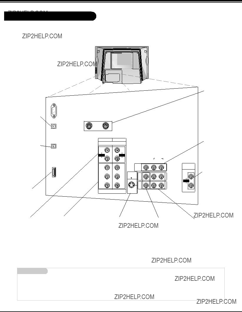
DESCRIPTION OF CONTROLS
Rear Connections Panel
Connecting external equipment to your TV.
CALIBRATION
Digital Audio
RF Connectors: Cable, Antenna Used to connect cable or antenna signals to the televi- sion, either directly or through your cable box.
Monitor Out Connects to a sec- ond TV or Monitor.
Variable Audio Out Used to connect either an external amplifier, or add a
Left/Right Audio
Used for stereo sound from various types of equipment.
Mini glossary
- 5 -
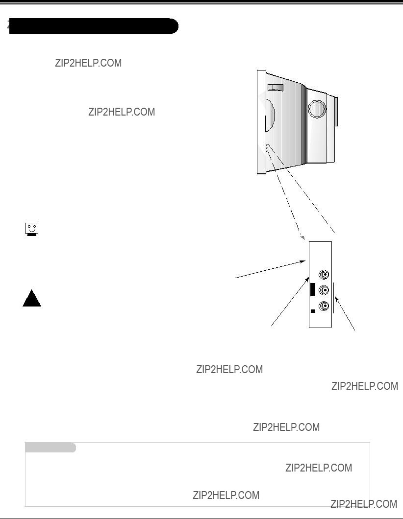
DESCRIPTION OF CONTROLS
Side Connections Panel
There are four jacks on the
The jacks are like those found on the back jack connection panel. This means that most equipment that connects to those types of jacks on the rear jackpack, may be connected to the Side connection panel (FRONT VIDEO).
To use the Side jacks as the signal source, select them using Input source menu as described on page 25. They will be named ???front Video??? in the Input source menu.
When you select Side video or Side
Do not connect to both Video and
A connection available on some very
Video in
Connects the video signals from any piece of equipment.
Side A/V Panel 

 VIDEO-S
IN VIDEO
L/MONO
AUDIO
R
FRONT VIDEO
Left/Right Audio
Used for stereo sound from various types of equipment.
Mini glossary
A/V CABLESAudio/Video cables. Three cable
A/V DEVICE Any device that produces video (picture) and/or audio (sound) (VCR, DVD, cable box, or television).
- 6 -

DESCRIPTION OF CONTROLS
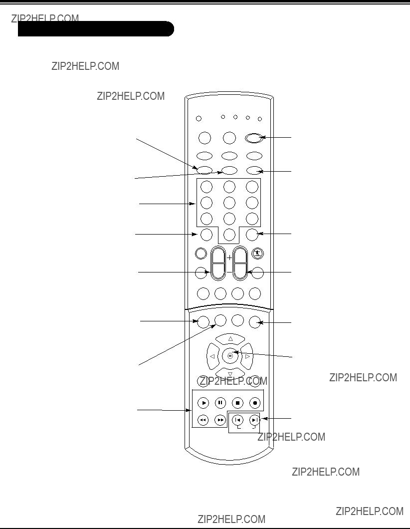
Remote Control Functions in TV Mode
MODE
Selects the remote operating mode: TV, VCR, Cable, DVD or Satellite. Select other operating modes, for the remote to oper- ate external devices.
TV INPUT
Selects: TV and CATV.
TV/VIDEO
Selects: Antenna, Cable, Video1, Video2, Front video, Component
MUTE
Switches the Mute or the EZ mute. Mute: The sound is off. EZ mute: The sound is off, and the caption is display.
EZ SOUND
Adjusts the factory preset picture according to the room.
RATIO
Changes the aspect ratio.
FREEZE
Captures and freezes the
THUMBSTICK
Allows you to navigate the
MENU
Brings up the main menu to the screen.
MODE INDEX POWER
 INPUT TV/VIDEO COMP1
COMP2 HDMI FRONT
1 2 3
4 5 6
7 8 9
RATIO FREEZE SAP SURROUND
INFO TIMER CC SIGNAL
PLAY PAUSE STOP RECORD
MODE INDICATOR
LIGHTS
Show active remote mode every time any button is pressed.
INDEX
Switches LED Display on or off.
COMP1
Selects the Component 1 input source.
FAV
Use to scroll the FAV chan- nel list.
EZ PIC
Adjusts the factory preset picture depend- ing on the viewing environment.
SURROUND
Selects : Off, 3D
EchoSound System and
SRS TruSurround XT.
SAP
Selects MTS sound: Mono,
Stereo, and SAP.
Change the audio language in
DTV mode.
CC
Lets you select a closed caption mode for displaying captioning information when provided for DTV/Analog signal.
EXIT
Clears all
REW FF
 SKIP
SKIP 
- 7 -
DESCRIPTION OF CONTROLS
Remote Control Functions in TV Mode
COMP2
Selects the Component 2 input source.
HDMI
Selects the HDMI input source.
NUMBER KEYPAD
For direct channel selection and programming functions.
Is used to enter a program number for multiple program channels such as
VOLUME UP/DOWN
Increases/decreases the sound level.
INFO
When you watch the TV, dis- plays information on top of the screen. Not available in Component
TIMER
Lets you select the amount of time before your TV turns itself off automatically.
RECORD, PAUSE, REW,
FFWD, PLAY, STOP
Control the functions on your VCR.
RATIO FREEZE SAP SURROUND
INFO TIMER CC SIGNAL
POWER
Turns your TV or any other programmed equipment on or off, depending on mode.
FRONT
Selects the front video input source.
FLASHBK
Use to scroll the recent chan- nel list.
CHANNEL UP/DOWN
Scrolls through available chan- nels present in EZ Scan memory.
SIGNAL
Displays the digital signal strength.
ENTER
When in the menu system and other
SKIP LEFT/RIGHT
Playing CDs: Selects songs.
Playing DVDs: Selects movie chapters.
- 8 -
SPECIFICATIONS
Product Specifications


 Design and specifications are subject to change without prior notice.
- 9 -
ADJUSTMENT INSTRUCTIONS
1. Application Object
These instructions are applied to the
2.Notes
(1)Because this is not a hot chassis, it is not necessary to use an isolation transformer. However, the use of an isolation transformer will help protect test instruments.
(2)Adjustments must be done in the correct order.
(3)The input voltage of the receiver must remain at 120V??10% while adjusting.
(4)The receiver must be operated for about 20 minutes prior to the adjustment.
[Never operate the set over 10 minutes with a still picture because a fluorescent material may get damage.
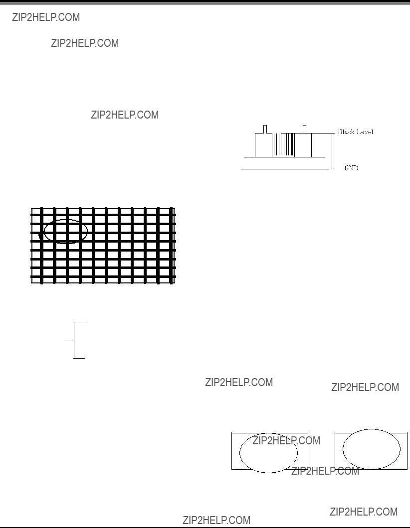
3.Focus Adjustment
A 
(1) Set Picture condition to ???APC ON???.
CONTRAST : 100
BRIGHT : 50
APC ON TINT : 55
COLOR : 0
SHARPNESS : 55
(2)Set the Aspect ratio to Wide Mode.
(3)Receive a Cross Hatch Pattern, adjusting the FOCUS Knob on the flyback transformer for the best focus in the area designated ???A??? above.
[ Heat run over 15 minutes before adjustment.
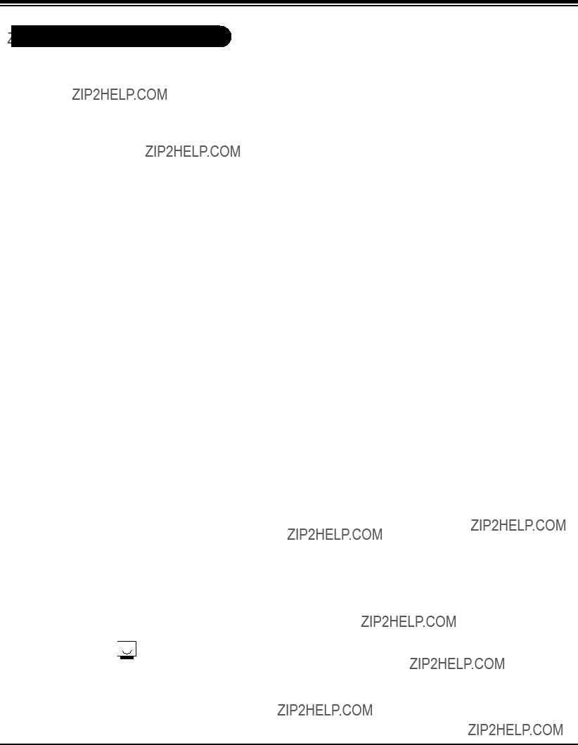
(1)Select EZ Adjust 3.
When it enters to adjustment mode, the pattern from a signal generator is being selected, it becomes with Normal image 16:9 and the
(2)Connect the oscilloscope ground lead to GND on the CPT board and the probe to the GK pin connector of the CPT socket.
Using the SCREEN knob on the Flyback Transformer, adjust the black level voltage to 180??2V.
 180??2V
(SCREEN voltage adjustment OSCILLOSCOPE, 100:1 PROBE, VOLTS/DIV : 0.5V/DIV SEC/DIV : 5us, The TRIGGER MODE it puts in the
5. Deflection Adjustment
Select EZ Adjust 1. Raster, Cent, H/V Size by using the ADJ key on the SVC Remote control.
In the adjustment mode a Digital Pattern signal signal is displayed.
Select 62.
(Overscan : 10%)
(1)Select 59.
(2)Adjust until the smaller inscribed circle coincides with the outer frame of screen.
(3)Select 95.
4.
(1)Service remote control
(2)Oscilloscope(100:1) Probe
- 10 -
ADJUSTMENT INSTRUCTIONS
Select 77. H Postion in the adjustment mode and adjust until left and right screen are symmetrically equal.
(1)Reduce 66
(2)Adjust the horizontal size, using a test pattern.
(1)Select EZ Adjust 2.
(2)Select
6.Component AD9883A Offset/Gain Adjustment
(1)SVC Remote Control,
(2)801GF(802B, 802F, 802R) pattern generator
<1080I Hoz30Bar Pattern>
7. White Balance Adjustment
Perform the screen adjustment first.
Color Temp must be adjusted from Medium Mode.
(The image condition must be adjusted from Normal condition) Manual adjustment is also possible by the following sequence.
(1)Receive White Pattern.
(2)Set screen size to wide mode
(3)Select EZ Adjust 4. White Balance on the SVC Remote control.
(4)Adjustment
1.Set an image with Normal image.
2.Adjust
3.Adjust ???CONTRAST??? and ???BRIGHT??? so the bright level is 4.5??0.5Ft_L.
4.Adjust
5.Repeat 1 ~ 4 until the color coordinates in High and Low color satisfies the Table.
6.Check the adjusted color coordinates with the white balance meter.
High Light : x=287!3, y=293!3
Low Light : x=287!3, y=293!3
Color temperature :
[The White Balance it executes from automatic adjustment hour Normal image condition.
Start adjustments from initial setting of R.DRIVE=31, G.DRIVE=31, B.DRIVE=31, R.CUT=31, G.CUT=31, B.CUT=31.
(1)Turn the power supply on.
(2)Enter the Component mode.
(3)Receive the 1080I, Hoz30Bar Pattern of the 801GF.
(1)After receiving a signal press the ADJ Key on the SVC Remote Control repeatedly to acess the Adjustment mode.
(2)#9. Set Adjustment will set the AD9883A automatically.
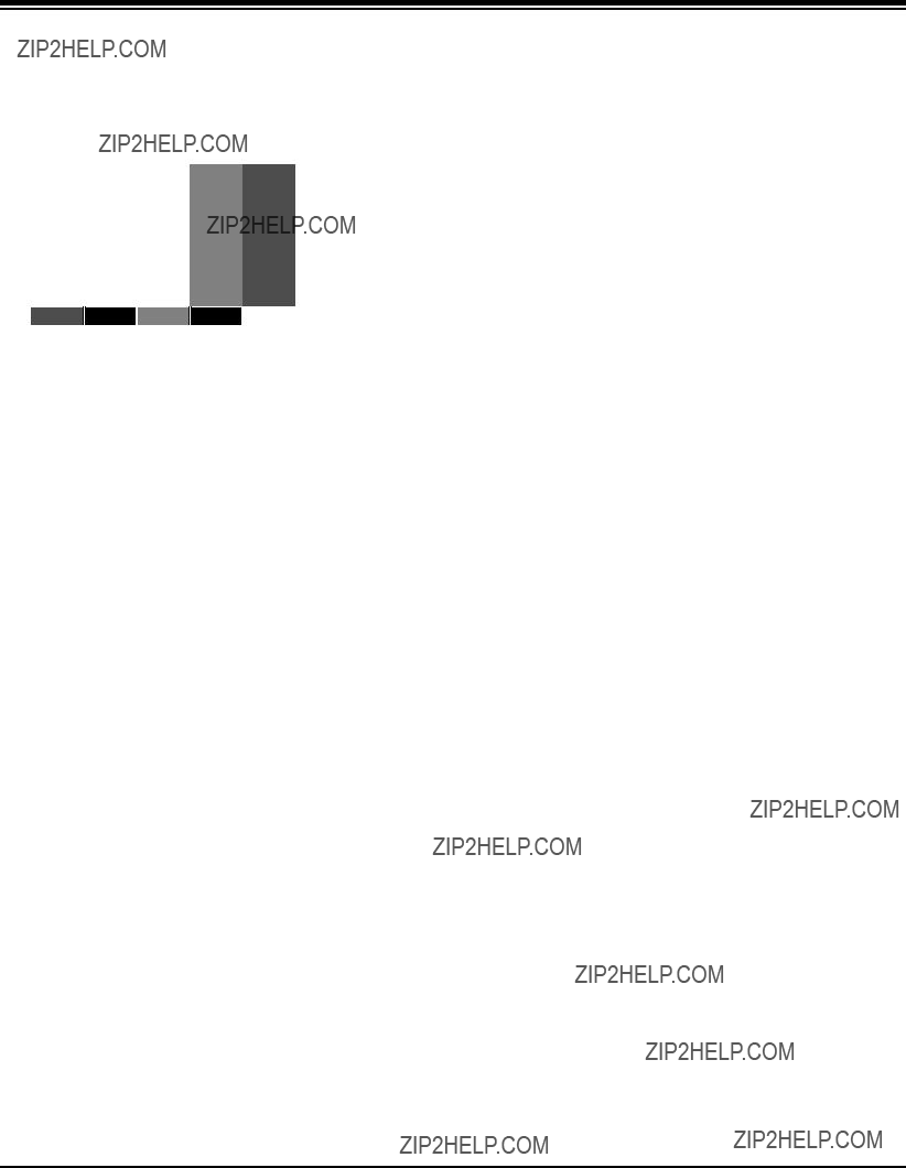
8. Sub Bright, TINT, COLOR Adjustment
0 1 2 3 4 5 6 7 8 9
US14CH
- 11 -
ADJUSTMENT INSTRUCTIONS
(1)Select EZ Adjust 5. Sub Bright pressing ADJ key on the SVC Remote control.
(2)Adjust to the point where ???2??? is not visible.
(1)Select EZ Adjust 6. Sub Tint, Color pressing ADJ key on the SVC Remote control.
(2)Select SUB COLOR and adjust the 1 and 1??? portion not to be classified.
(3)Select SUB TINT and adjust the 3 and 3??? portion not to be classified.
- 12 -
PURITY & CONVERGENCE ADJUSTMENT
Caution:
Convergence and Purity have been factory aligned. Do not attempt to tamper with these alignments.
However, the effects of adjacent receiver components, or replacement of picture tube or deflection yoke may require the readjustment of purity and convergence.
5.Reconnect the internal degaussing coil.
6.Position the beam bender locking rings at the 9 o'clock position and the other three pairs of tabs (2,4 and 6 pole magnets) at the 12 o'clock position.
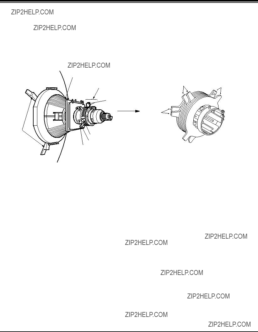
?? Purity Adjustment
This procedure DOES NOT apply to bonded yoke and picture tube assemblies.
The instrument should be at room temperature (60 degrees F or above) for six (6) hours and be operating at low beam current (dark background) for approximately 20 to 30 minutes before performing purity adjustments.
CAUTION: Do not remove any trim magnets that may be attached to the bell of the picture tube.
1.Remove the AC power and disconnect the internal degaussing coil.
2.Remove the yoke from the neck of the picture tube.
3.If the yoke has the tape version beam bender, remove it and replace it with an adjustable type beam bender (follow the instructions provided with the new beam bender)
4.Replace the yoke on the picture tube neck, temporarily remove the three (3) rubber wedges from the bell of the picture tube and then slide the yoke completely forward.
7.Perform the following steps, in the order given, to prepare the receiver for the purity adjustment procedure.
a.Face the receiver in the "magnetic north" direction.
b.Externally degauss the receiver screen with the television power turned off.
c.Turn the television on for approximately 10 seconds to perform internal degaussing and then turn the TV off.
d.Unplug the internal degaussing coil. This allows the thermistor to cool down while you are performing the purity adjustment. DO NOT MOVE THE RECEIVER FROM ITS
"MAGNETIC NORTH" POSITION.
e.Turn the receiver on and obtain a red raster by increasing the red bias control (CW) and decreasing the bias controls for the remaining two colors (CCW).
f.Attach two round magnets on the picture tube screen at 3 o'clock and 9 o'clock positions, approximately one (1) inch from the edge of the mask (use
- 13 -
PURITY & CONVERGENCE ADJUSTMENT
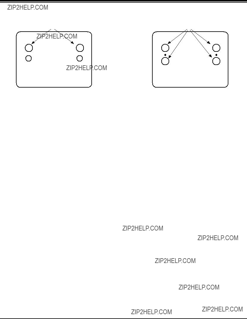
1.ADJUST YOKE
TO GET EQUAL BLUE
COLOR CIRCLES

 MAGNETS

RED
8.Referring to above, perform the following two steps:
a.Adjust the yoke
b.Adjust the appropriate beam bender tabs to obtain correct purity (four equal circles).
9.After correct purity is set, tighten the yoke clamp screw and remove the two screen magnets.
10.Remove the AC power and rotate the receiver 180 degrees (facing "magnetic south").
11.Reconnect the internal degaussing coil.
12.Turn the receiver on for 10 seconds (make sure the receiver came on) to perform internal degaussing, and then turn the receiver off.
13.Unplug the internal degaussing coil.
14.Turn the receiver on and check the purity by holding one (1) round magnet at the 3 o'clock and a second round magnet at 9 o'clock position. If purity is not satisfactory, repeat steps 8 through 14.
15.Turn off the receiver and reconnect the internal degaussing coil.
?? Convergence Adjustment
Caution: This procedure DOES NOT apply to bonded yoke and picture tube assemblies.
Do not use screen magnets during this adjustment procedure. Use of screen magnets will cause an incorrect display.
1.Remove AC power and disconnect the internal degaussing coil.
2.Apply AC Power and set the brightness to the Picture Reset condition. Set the Color control to minimum.
3.Make horizontal line.
4.Adjust the Red, Green and Blue Bias controls to get a dim white line.
2 .ADJUST BEAM BENDER 2 POLE
MAGNET TO GET FOUR EQUAL
COLOR CIRCLES
RED
5.Restore the screen by removing the horizontal line.
6.Reconnect the internal degaussing coil and apply AC power.
7.Turn the receiver on for 10 seconds to perform internal degaussing and then turn the receiver off again.
8.Unplug the internal
9.Turn the receiver on, connect a signal generator to the VHF antenna terminal and apply a crosshatch signal.
Caution: During the convergence adjustment procedure, be very careful not to disturb the purity adjustment tabs. Purity should be confirmed before proceeding with the convergence adjustments.
Note: Make sure the focus is set correctly on this instrument before proceeding with the following adjustment.
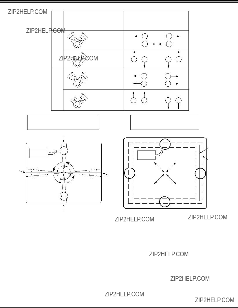
10.Converge the red and blue vertical lines to the green vertical line at the center of the screen by performing the following steps (below TABLE).
a.Carefully rotate both tabs of the
b.Carefully rotate both tabs of the
11.Converge the red and blue horizontal with the green line at the center of the screen by performing the following steps. (below TABLE)
a.Carefully rotate both tabs of the
b.Carefully rotate both tabs of the
c.Secure the tabs previsouly adjusted by locking them in place with the locking tabs on the beam bender.
- 14 -
PURITY & CONVERGENCE ADJUSTMENT
UP/DOWN ROCKING OF THE YOKE CAUSES
OPPOSITE ROTATION OF RED AND BLUE
RASTERS
GREEN
LEFT/RIGHT ROCKING OF THE YOKE
CAUSES OPPOSITE SIZE CHANGE OF
THE RED AND BLUE RASTERS
GREEN
12.While watching the 6 o'clock positions on the screen, rock the front of the yoke in a vertical (up/down) direction to converge the red and blue vertical lines. (Fig upper left)
13.Temporarily place a rubber wedge at the 12 o'clock position to hold the vertical position or the yoke.
14.Check the 3 o'clock and 9 o'clock areas to confirm that the red and blue horizontal lines are converged.
If the lines are not converged, slightly offset the vertical tilt of the yoke (move the rubber wedge if necessary) to equally balance the convergence error of the horizontal lines at 3 o'clock and 9 o'clock and the vertical lines at 6 o'clock and 12 o'clock.
15.Place a 1.5 inch piece of glass tape over the rubber foot at the rear of the 12 o'clock wedge.
16.While watching the 6 o'clock and 12 o'clock areas of the screen, rock the front of the yoke in the horizontal (left to right) motion to converge the red and blue horizontal lines.
(Fig. upper right)
17.Temporarily place a rubber wedge at the 5 o'clock and 7 o'clock positions to hold the horizontal position of the yoke.
18.Check the 3 o'clock and 9 o'clock areas to confirm that the red and blue vertical lines are converged. If the lines are not converged, slightly offset the horizontal tilt of the yoke (move the temporary rubber wedges if necessary) to equally balance the convergence error of the horizontal lines at 6 o'clock and 12 o'clock and the vertical lines at 3 o'clock and 9 o'clock.
19.Using a round magnet confirm purity at the center, right and left sides and corners. See Purity Adjustment Procedure.
20.Reconfirm convergence and apply a 1.5 inch piece of glass tape over the rubber foot at the rear of the 5 o'clock and the 7 o'clock wedges.
- 15 -
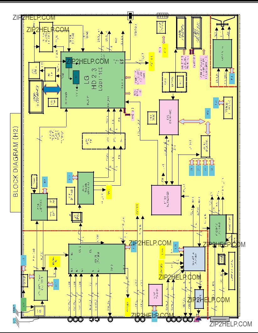
BLOCK DIAGRAM
???
- 16 -
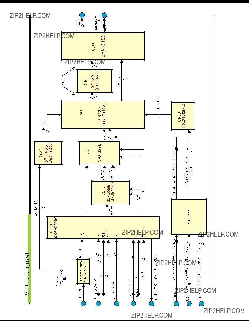
BLOCK DIAGRAM
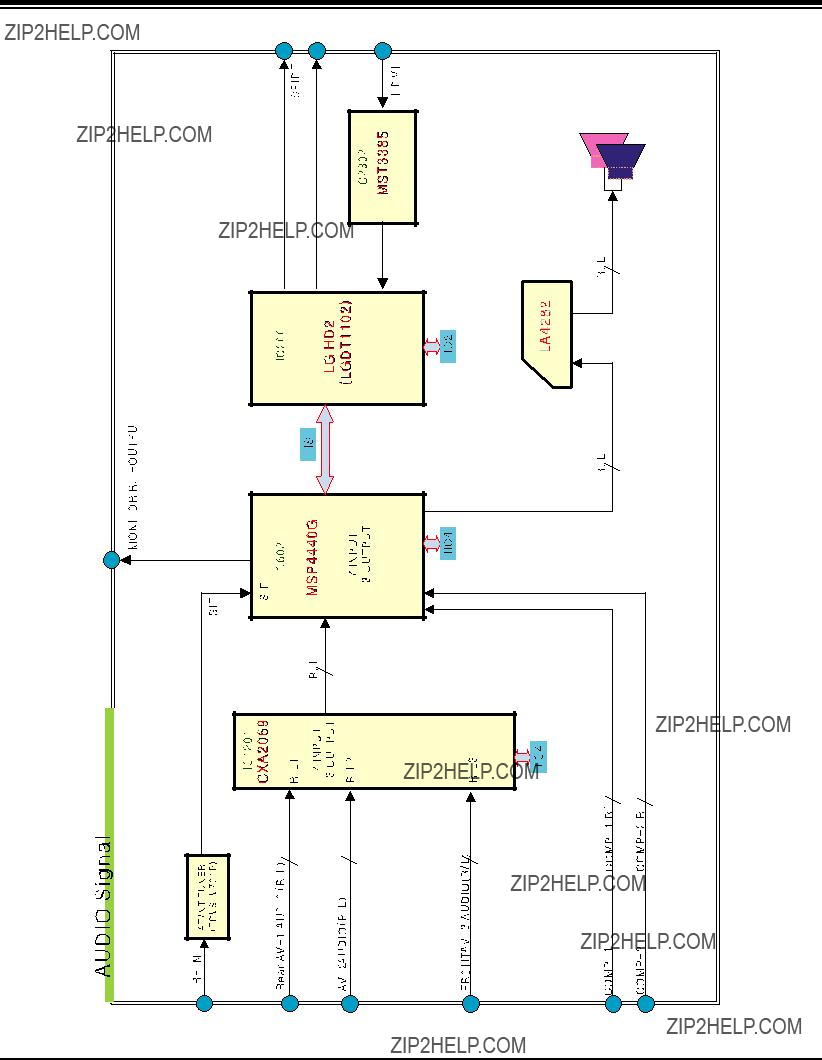
BLOCK DIAGRAM

NOTES
- 19 -

EXPLODED VIEW
943
400
912
510
170 150
503
530
 550
550
300
700
310
- 20 -
EXPLODED VIEW PARTS LIST
- 21 -

REPLACEMENT PARTS LIST
- 22 -
REPLACEMENT PARTS LIST
- 23 -

REPLACEMENT PARTS LIST
- 24 -

REPLACEMENT PARTS LIST
- 25 -
REPLACEMENT PARTS LIST
- 26 -

REPLACEMENT PARTS LIST
- 27 -
REPLACEMENT PARTS LIST
- 28 -

REPLACEMENT PARTS LIST
- 29 -

REPLACEMENT PARTS LIST
- 30 -
CANADA: LG Electronics Canada, Inc. 550 Matheson
Boulevard East Mississauga, Ontario L4Z 4G3


MAIN(BOTTOM)