E 2
E 2

IMPORTANT SAFETY INSTRUCTIONS
1)Read these instructions.
2)Keep these instructions.
3)Heed all warnings.
4)Follow all instructions.
5)Do not use this apparatus near water.
6)No objects filled with liquids, such as vases, shall be placed on the apparatus.
7)Clean only with dry cloth.
8)Do not block any ventilation openings, install in accordance with the manufacturer???s instructions.
9)Do not install near any heat sources such as radiators, heat registers, stoves, or other apparatus (including amplifiers) that produce heat.
10)Do not defeat the safety purpose of the polarized or grounding- type plug. A polarized plug has two blades with one wider than the other. A grounding type plug has two blades and a third grounding prong. The wide blade or the third prong are pro- vided for your safety. If the provided plug does not fit into your outlet, consult an electrician for replacement of the obsolete outlet. (for U.S.A. and Canada)
11)Protect the power cord from being walked on or pinched particularly at plugs, convenience receptacles, and the point where they exit from the apparatus.
12)Only use attachments/accessories specified by the manufac- turer.
13)Unplug this apparatus during lightning storms or when unused for long periods of time.
14)Refer all servicing to qualified service personnel. Servicing is required when the apparatus has been damaged in any way, such as
15)Do not install this equipment on the far position from wall outlet and/or convenience receptacle.
16)Do not install this equipment in a confined space such as a box for the conveyance or similar unit.
17)Use only with the cart, stand, tripod, bracket, or table specified by the manufacturer, or sold with this apparatus. When a cart is used, use caution when moving the cart/apparatus combination to avoid injury from
The lightning flash with arrowhead symbol within an equilateral triangle, is intended to alert the user to the presence of uninsulated ???dangerous voltage??? within the product???s enclosure that may be of sufficient magnitude to constitute a risk of electric shock to persons.
The exclamation point within an equilateral triangle is intended to alert the user to the presence of important operating and mainte- nance (servicing) instructions in the literature accompanying the product.
THE FCC REGULATION WARNING (for U.S.A.)
This equipment has been tested and found to comply with the limits for a Class B digital device, pursuant to Part 15 of the FCC Rules. These limits are designed to provide reasonable protection against harmful interference in a residential installa- tion. This equipment generates, uses, and can radiate radio frequency energy and, if not installed and used in accordance with the instructions, may cause harmful interference to radio communications. However, there is no guarantee that interfer- ence will not occur in a particular installation. If this equipment does cause harmful interference to radio or television reception, which can be determined by turning the equipment off and on, the user is encouraged to try to correct the interference by one or more of the following measures:
???Reorient or relocate the receiving antenna.
???Increase the separation between the equipment and receiver.
???Connect the equipment into an outlet on a circuit different from that to which the receiver is connected.
???Consult the dealer or an experienced radio/TV technician for help.
Unauthorized changes or modification to this system can void the user???s authority to operate this equipment.
CE mark for European Harmonized Standards
CE mark which is attached to our company???s products of AC mains operated apparatus until December 31, 1996 means it conforms to EMC Directive (89/336/EEC) and CE mark Directive (93/68/EEC).
And, CE mark which is attached after January 1, 1997 means it conforms to EMC Directive (89/336/EEC), CE mark Directive (93/68/EEC) and Low Voltage Directive (73/23/EEC).
Also, CE mark which is attached to our company???s products of Battery operated apparatus means it conforms to EMC Directive (89/336/EEC) and CE mark Directive (93/68/EEC).
II

Thank you for purchasing the Korg
About this owner???s manual
How this manual is organized, and how to use it
Please read this manual carefully to learn important points and basic operation.
???Introduction??? explains the features of the
???Quick Start??? explains how to play the demo songs, and perform basic operations.
???Basic functions??? explains basic operations for playing the
???Parameters??? explains the operation and settings for each parameter, organized by mode. Refer to this section when an unfamiliar parameter is displayed, or when you want to learn more about a function.
???Appendix??? explains how to connect a MIDI sequencer or computer, or perform a data dump. A list of the
Printing conventions in this manual
Keys and knobs ... [ ]
Keys and knobs etc. on the front panel of the
Parameters
Parameters that appear in the display are enclosed in quotation marks ??? ???.
p. ???
This indicates a page for reference.
 symbol
This symbol indicates a cautionary note.

 symbol
This symbol indicates a useful hint or application.
Display screen
The parameter values and program names etc. appearing in the screens printed in this manual are only examples; they will not necessarily match the values or names that appear in the screen of your
CC# is an abbreviation for Control Change Number. In the context of a MIDI message, all numbers in square brackets [ ] are in hexadecimal notation.
III

Table of Contents
IV
1. About the
Drawbars and tone generators
Normal mode
Main features
The
Korg's technology is used to create spatial effects such as rotary speaker, chorus/vibrato, and reverb, faithfully simulating the modulated sounds produced by the turning rotor and horn, the natural overdrive, and chorus/vibrato to produce the authentic combo organ experience. The

 2 Drawbar 1 Drawbar
MIDI CC#
By operating the two sets of drawbars you can modify the sound in realtime while you play. The sound is created using one set of drawbars in Normal mode, or by using both sets in EX mode. In EX mode, you can introduce additional tonal and percussion harmonics, letting you produce new sounds unavailable until now.
A conventional keyboard does not sound until a key is pressed down all the way, but the
The
There are 128 internal programs (Normal mode: 64, EX
mode: 64) that let you enjoy a variety of organ sounds.
EX mode
MIDI CC#
The
To create the sound, the
The keys in the DRAWBAR SELECT section let you choose which set of drawbars is active (see the diagram).
 (Resonant structure and Electronic circuit Modeling System) is KORG???s proprietary sound modeling technology which precisely reproduces the complex character and nature of both acoustic and electric instruments as well as electronic circuits in real world environments. REMS emulates a wide variety of sound generation characteristics including instru- ment bodies, speakers & cabinets, acoustic fields, microphones, vacuum tubes, transistors, etc.
The modes of the
Normal mode and EX mode
In these modes you can select and play programs. The main differences between Normal mode and EX mode are given below.
Normal mode
??? The sound is created by one set of drawbars
EX mode
??? The sound is created by two sets of drawbars
Normal Edit mode and EX Edit mode
In this mode you can edit the program parameters of Normal mode or EX mode.
Global mode
In this mode you can make settings that affect the entire
5
Introduction
2. Parts of the
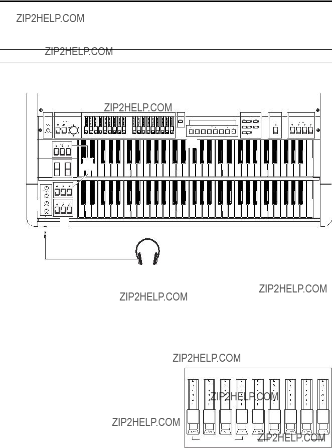
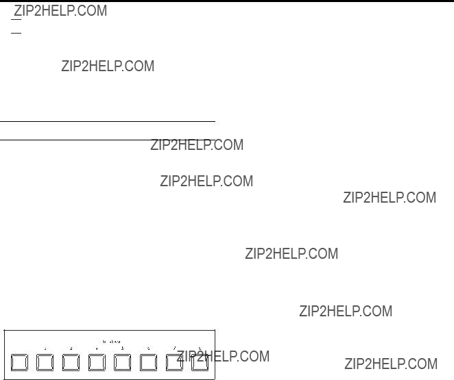
Front panel
12
11

 PHONES jack
1. [EXPRESSION/OVERDRIVE] knob
This simultaneously adjusts the volume and distor- tion. At low volumes, the low frequency and high frequency regions will be emphasized slightly.
2. VIBRATO/CHORUS section [UPPER] key, [LOWER] key
These keys select the keyboard to which vibrato or chorus will be applied.
When you press a key to turn it on, its LED will light.
[VIBRATO/CHORUS] knob
3. DRAWBAR section
Drawbar 1, Drawbar 2
Drawbar 1 is at the left, and Drawbar 2 at the right. Each bar is assigned a pitch (footage), and you can adjust the volume of that pitch by pulling the bar toward yourself. The overall character of the sound is determined by how far each bar is pulled out.
In EX mode, Drawbar 2 is used to control EX Drawbar and EX Percussion. For details, refer to ???Playing the
6
Introduction
4. [DISPLAY] key
The contents of the display will change each time you press this key.
The display will differ between Normal mode and EX mode. For details, refer to ???1. About the display??? (p.14).
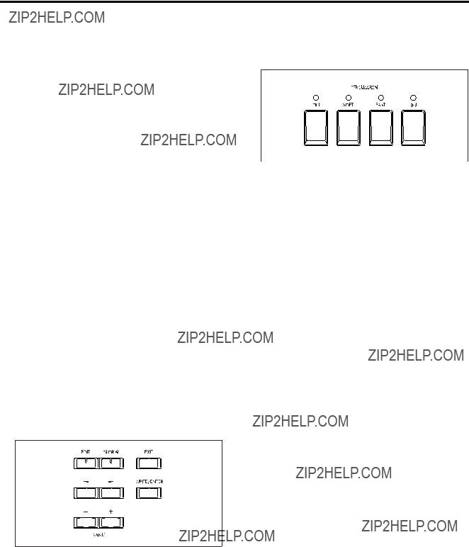
5. [EDIT] key
Press this key to enter Normal Edit mode or EX Edit mode
In Normal mode, pressing this key will enter Normal Edit mode. In EX mode, pressing this key will enter EX Edit mode.
[GLOBAL] key
Press this key to enter Global mode.
[EXIT] key
Press this key to exit from Normal Edit mode, EX Edit mode, or Global mode, or to cancel an operation such as program write, copy, swap, or data dump.
[WRITE/ENTER] key
Press this key to execute an operation such as pro- gram write, copy, swap, or data dump.
[??? ]/[??] keys
In Normal Edit mode, EX Edit mode, and Global mode, use these keys to move to the previous or next page, or to move the cursor to the left or right in the display.
In Normal mode and EX mode, use these keys to select banks of preset programs.
In Normal Edit mode, EX Edit mode, and Global mode, use these keys to edit the value of a parameter.
Pressing and releasing a key will change the value in steps of 1, and holding down a key will change the value continuously.
6. [EX MODE] key
Press this key to enter EX mode.
7. PERCUSSION section
Here you can add an attack to the beginning of the notes, making the sound more crisp.
For details, refer to ???4. Percussion??? (p.17).
[ON] key
This switches percussion on/off.
When this is off, the [3rd] key, [SOFT] key, and [FAST] key will have no effect.
LED lit: Percussion will be on.
[SOFT] key
This switches the percussion volume (soft or normal).
LED lit: The percussion volume will be lowered.
[FAST] key
This switches the percussion decay speed (fast or slow).
LED lit: The decay will be faster.
[3rd] key
This switches the pitch of the percussion sound between the 3rd and 2nd harmonics.
When you are using the EX mode drawbars, this setting is assigned to the
LED lit (3rd): A pitch one octave and a fifth higher (corresponding to
LED dark (2nd): A pitch one octave higher (corre- sponding to 4') will be assigned to the percussion effect.
8. PROGRAM
In Normal mode and EX mode, these keys are used to directly select a preset program from within a bank.
In Normal Edit mode, EX Edit mode, and Global mode, these keys are used as shortcuts to select parameters (p.15).
7
Introduction
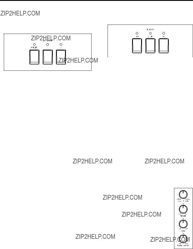
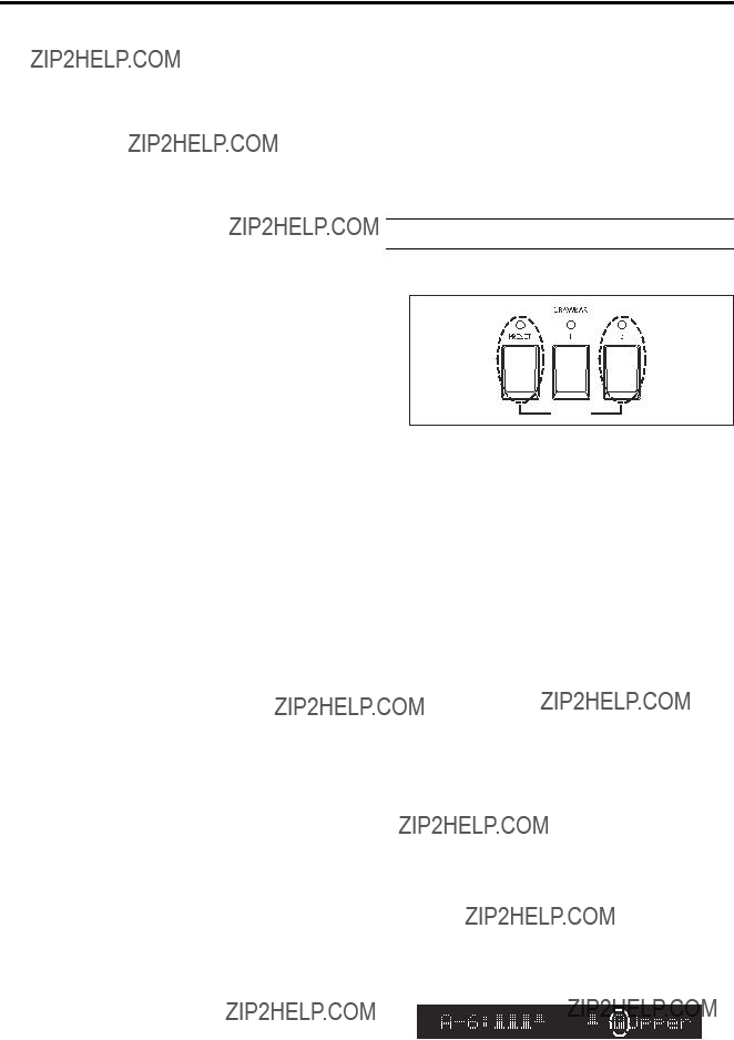
9. DRAWBAR SELECT section
The upper three drawbar select keys are for the upper keyboard, and the lower three are for the lower keyboard. When you press a key to turn it on, its LED will light.
Use these keys to select the drawbar settings that will be played by the upper or lower keyboards.
If you select the [DRAWBAR 1] key, the keyboard will play the settings of the front panel Drawbar 1 section. The Drawbar 2 settings will be used if you select the [DRAWBAR 2] key, and the drawbar parameters specified by the program will be used if you select the [PRESET DRAWBAR] key.
If you press the [PRESET DRAWBAR] key when its LED is blinking or dark, the drawbar parameter settings will be shown in the display for approxi- mately 1 second.
In EX mode, the [PRESET DRAWBAR] key will automatically be selected for the lower keyboard (neither of the other Drawbar settings can be selected).
10. Pitch Bend wheel, Modulation wheel
These wheels let you control tone, pitch, and volume etc. in realtime while you play. The bender wheel is at the left, and the modulation wheel at the right.
Pitch Bend wheel
Move this wheel away from yourself to raise the pitch. Move it toward yourself to lower the pitch.
Modulation wheel
Move this wheel away from or toward yourself to apply the effect that is assigned to the modulation wheel.
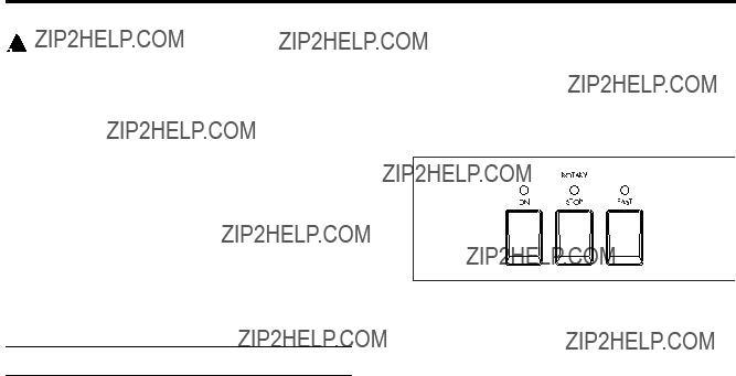
11. ROTARY section
Here you can control the rotary effect.
For details, refer to ???5. Rotary??? (p.18).
[ON] key
This key turns the rotary speaker effect on or off. When this is off, pressing the [FAST] or [STOP] keys will have no effect.
LED lit: The rotary speaker effect is on.
[STOP] key, [FAST] key
These keys control the rotary speaker.
When the [STOP] key LED is dark: The [FAST] key will switch the rotary speaker between fast and slow. The rotary speaker will turn rapidly when you make the [FAST] key LED light.
The rotary speaker will turn slowly when you make the [FAST] key LED go dark.
When the [STOP] key LED is lit: The [FAST] key will switch the rotary speaker between fast and stopped. The rotary speaker will turn rapidly when you make the [FAST] key LED light.
The rotary speaker will stop turning when you make the [FAST] key LED go dark.
When the [FAST] key LED is dark: The [STOP] key will switch the rotary speaker between slow and stopped.
The rotary speaker will stop turning when you make the [STOP] key LED light.
The rotary speaker will turn slowly when you make the [STOP] key go dark.
12. AMP section
[MASTER LEVEL] knob
Use this knob to adjust the volume as appropriate for the equipment to which the
Use the [EXPRESSION/OVERDRIVE] knob and a connected expression pedal to adjust the volume and distortion of the sound, and then use this knob to set the final output level.
[TREBLE] knob
Adjusts the
[BASS] knob
Adjusts the
[REVERB OFFSET] knob
Adjust the reverb depth.
When this knob is at the center position, the reverb will be the depth specified by the program. When this knob is turned to the far left there will be no reverb, and when turned to the far right the reverb will be deeper.
8
Introduction
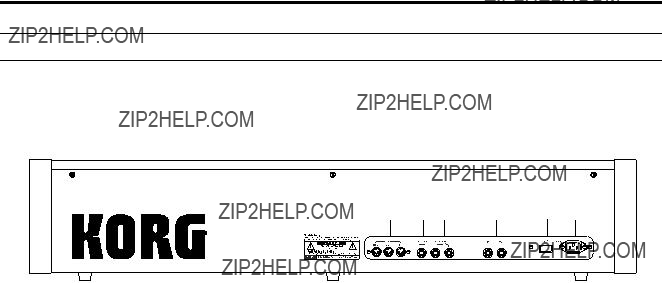
Rear panel
1. MIDI IN connector
Musical data and sound settings etc. can be received at this connector.
Use this connector when you wish to play the
MIDI OUT connector
Music data and sound settings etc. can be transmitted from this connector.
Use this connector when you wish to control a connected MIDI device.
5. Power switch
This turns the power on/off.
6. AC power inlet
Connect the included power cable here.
After connecting the power cable to the
MIDI THRU connector
Music data and sound settings etc. received at the MIDI IN connector are
Use this connector when you wish to connect multiple MIDI devices.
2. EXPRESSION PEDAL jack
Connect the included expression pedal to this jack. For details on the function of the expression pedal, refer to ???5. Operation of included Expression pedal??? (p.42).
3. ASSIGNABLE PEDAL/SW 1, 2 jacks
4. OUTPUT L, R jacks
Connect these jacks to the INPUT jacks of your amp or mixer.
These are unbalanced phone jacks.
When connecting in stereo, use the L and R jacks. When connecting in monaural, use the L jack.
9
Introduction
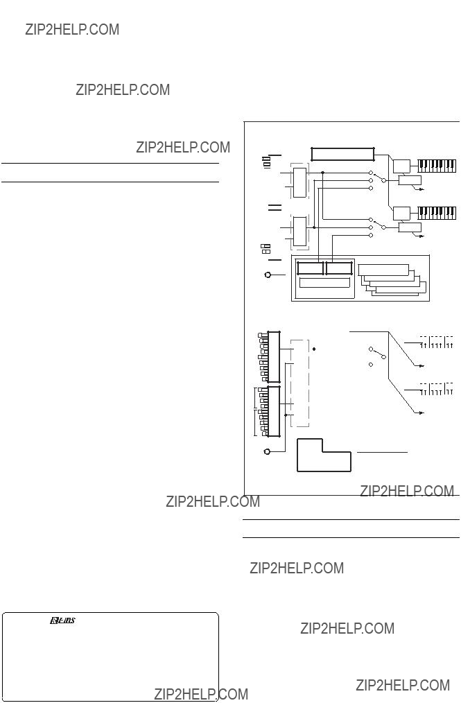
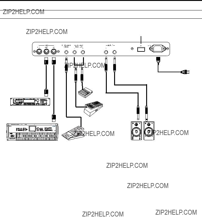
Connections
Power switch
to an AC outlet
Power cable (included)
INPUT 
Expression pedal (included)
Powered monitors, keyboard amps etc.
 Be sure that the power is off before you make any connections. Improper use can damage your speaker system etc., or may cause a malfunction.
1. Power cable connections
Connect the included power cable to the AC power inlet of the
2. OUTPUT jack connections
Connect powered monitors, keyboard amps, or your audio system to output the sound of the
 If you connect the
Connect the OUTPUT L, R jacks to the INPUT jacks of your powered monitors etc.
When connecting in stereo, use the L and R jacks. When connecting in mono, use the L jack. We recom- mend that you use stereo connections whenever possible.
3. Pedal connections
Pedal switch connections
The rotary speaker effect, vibrato/chorus on/off, and program selection can be controlled by a foot switch.
The function to be controlled can be specified by the parameters of Normal Edit mode, EX Edit mode, and Global mode.
Connect a separately sold Korg
Expression pedal connections
A pedal can be used to control the volume, etc.
The function to be controlled can be specified by the parameters of Normal Edit mode, EX Edit mode, and Global mode.
Connect the included expression pedal to the EX- PRESSION PEDAL jack, and a separately sold Korg
4. MIDI connections
MIDI connections allow you to use the keyboard and controllers (drawbars etc.) of the
Use a MIDI cable to connect the MIDI connector of the
10
1. Listening to the demo songs
Here's how to listen to the demo songs.
The
1.Turn on the power.
2.Press the [GLOBAL] key.
The [GLOBAL] key LED will light.
3.Press the PROGRAM [8] key, and then press the [WRITE/ENTER] key.
4.Press the [WRITE/ENTER] key once again.
The demo will begin playing.
When the first song ends, the next song will begin.
5.To stop the performance, press the [EXIT] key.

 After pressing the [WRITE/ENTER] key in step 3, you can press the
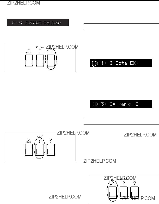
2. Normal mode
Selecting a program
Here???s how you can select and play program
1.Make sure that you are in Normal mode.
The program number will be shown at the left of the display.
If you are not in Normal mode (i.e., if the [EX MODE] key, [EDIT] key, or [GLOBAL] key LEDs are lit) press the lit key once. If the [EDIT] key or [GLOBAL] key LEDs are lit, you can also return to Normal mode by pressing the [EXIT] key.

 When you turn on the power, you will automatically be in Normal mode.
2.[Press the
Program
Playing
Playing using the Program???s drawbar settings
Here's how to use the drawbar settings stored as part of a program instead of using the front panel Drawbar 1 or 2 settings.
1.Select a program in Normal mode.
Use the
2.In both the upper and lower DRAWBAR SELECT sections, press the [DRAWBAR PRESET] key to make the key LED light.
3.Play the keyboard.
The upper keyboard will use the ???UPPER??? parameter settings of the program, and the lower keyboard will use the ???LOWER??? parameter settings of the program.
11
Quick Start
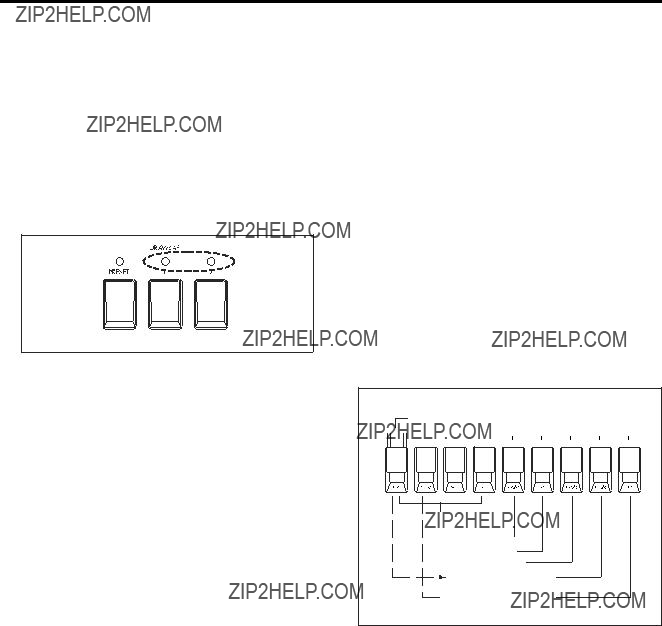
Using the Drawbar 1 and 2 settings
1.Make sure that you are in Normal mode.
2.In the DRAWBAR SELECT section located at the left of the upper keyboard, press the [DRAWBAR 2] key.
The key LED will light.
Now you can use the front panel Drawbar 2 section to adjust the tone of the upper keyboard.
3.While playing the upper keyboard, pull out the front panel Drawbar 2 bars to create the sound.
When you pull out each bar of Drawbar 2, the pitch (footage) printed on that bar will be added to the sound produced by the key. The volume of that pitch will depend on how far the bar is pulled out. In this way, the overall tone is determined by the combina- tion of bars that are pulled out.
For details on the pitches that are assigned to the bars, refer to ???1. How the drawbars work??? (p.36).
4.In the DRAWBAR SELECT section located at the left of the lower keyboard, press the [DRAWBAR 1] key.
The key LED will light.
Now you can use the front panel Drawbar 1 section to adjust the tone of the lower keyboard.
5.While playing the lower keyboard, pull out the front panel Drawbar 1 bars to create the sound.
When you pull out each bar of Drawbar 1, the pitch (footage) printed on that bar will be added to the sound produced by the key. The volume of that pitch will depend on how far the bar is pulled out. In this way, the overall tone is determined by the combina- tion of bars that are pulled out.
For details on the pitches that are assigned to the bars, refer to ???1. How the drawbars work??? (p.36).
6.Let's try selecting a program .
Use the
When you select a different program, the settings saved with the program (other than the drawbar parameters) will be recalled. In other words, the Drawbar 1 and 2 settings will remain in effect, and the other settings (for example, wheel type, percussion volume, reverb time, rotary speaker horn and rotor speed, etc.) of the selected program will be applied.
3. EX mode
Selecting a program
Here's how you can select and play program
3of bank B).
1.From Normal mode, press the [EX MODE] key.
The [EX MODE] key LED will light, indicating you are in the EX mode.
The display will show an ???E??? at the left, and the program number.
If an LED is lit for a mode other than EX mode (i.e., if the [EDIT] key or [GLOBAL] key LED is lit), press the lit key once, or press the [EXIT] key and then press the [EX MODE] key.
2.Use the
Program
Playing
Playing Using the Program???s drawbar settings
Here's how to play the drawbar settings saved with the program, instead of using the Drawbar 1 and 2 settings of the front panel.
1.In EX mode, select a program.
Use the
2.In the DRAWBAR SELECT section located at the left of the upper keyboard, press the [DRAWBAR PRESET] key to make the key LED light.
In the DRAWBAR SELECT section located at the left of the lower keyboard, the [DRAWBAR PRESET] key will be selected automatically. (The other two keys cannot be selected in the EX mode.)
3.Play the keyboard.
The upper keyboard will use the Drawbar 1 and EX Drawbar settings of the ???EX DRAWBAR & PERCUS- SION??? parameters, and the lower keyboard will use the settings of the ???EX LOWER??? parameters.
12
Quick Start
Using the Drawbar 1 and 2 settings
The upper keyboard will use both sets of Drawbars (1 and 2) on the front panel. Drawbar 2 is assigned to footages and percussion settings for the EX mode, allowing you to create richer and more expressive sounds than in Normal mode.
The lower keyboard will use the drawbar parameter settings that are specified by the program.
1.In EX mode, press the [DRAWBAR 1] key or [DRAWBAR 2] key of the upper DRAWBAR SE- LECT section. Make sure that the LEDs of both keys are lit.
2.While playing the upper keyboard, pull out the drawbars of front panel Drawbar 1 and 2 to create the sound.
Drawbar 1 adjusts the volume of the footage printed on each bar.
In the Drawbar 2 section, EX Drawbar (the four left bars) adjust the volume of the footage, and EX Percus- sion (the five right bars) adjust the volume of percus- sion.
Each bar is assigned as follows.
EX Drawbars
EX Percussion
2': 16' is assigned.
1': The footage assigned to the
3.Play the lower keyboard.
The lower keyboard will automatically use the sound of the drawbar parameters that are preset by the program, and in the lower DRAWBAR SELECT section, the [PRESET PROGRAM] key LED will light (the other two keys cannot be selected).

 If you want to change the preset drawbar settings, edit the parameters in EX Edit mode. For details, refer to ???Editing the drawbar parameters??? (p.21).
4.Selecting a different program.
Use the
When you select a different program, the program parameters other than the drawbar settings will be recalled and assigned to the sound.

 The lower keyboard will automatically use the drawbar parameter settings that are specified by the program, so if you want to change the sound of the lower keyboard while you play, you can prepare several programs that differ only in the drawbar parameter settings, and switch between these programs while you play.
Drawbar 2
Depends on the setting of the ???Ex Drawbar Type???
Depends on the setting of the ???Ex Drawbar Type???parameter*
 Depends on the setting of the ???Ex Drawbar Type???parameter*
*Refer to EX Edit mode ???Ex Drawbar Type??? (p.25), and Global mode Group 6 (p.33).
13

1. About the display
Switching the display
Each time you press the [DISPLAY] key, the contents of the display will change as follows.
Normal mode
When you are in the Normal mode, the display will show the program number and program name.
When you press the [DISPLAY] key, the display will show the settings of the ???UPPER??? parameters (drawbar
parameters for the upper keyboard) specified by the
program.
When you press the [DISPLAY] key again, the display will show the settings of the ???LOWER??? parameters
(drawbar parameters for the lower keyboard).
When you press the [DISPLAY] key once again, the program number and program name display will reappear.

 Front panel Drawbar 1 and 2 settings can be changed not only by moving the bars manually, but also by receiving MIDI control change messages. If MIDI control changes are received to modify the sound, the ???LOWER??? parameter display will show the values as follows.
Program number and program name
???UPPER??? parameter settings
???DB Preset???s Perc??? settings
???LOWER??? parameter settings
(Display when drawbar levels have been edited by MIDI CC#)
EX mode
When you are in the EX mode, the display will show the program number and program name.
When you press the [DISPLAY] key, the display will show
the settings of the ???EX DRAWBAR & PERCUSSION??? parameters Drawbar 1 and EX Drawbar that are specified by the program.
When you press the [DISPLAY] key again, the display will show the settings of the ???EX Percussion??? param- eters.
When you press the [DISPLAY] key again, the display will show the settings of the ???EX LOWER??? parameters.
When you press the [DISPLAY] key yet another time, the program number and program name display will reappear.

 If MIDI control changes were received to change the sound, these values will be displayed following the ???EX LOWER??? parameter display, in the same way as for Normal mode.
Program number and program name
Drawbar 1 and EX Drawbar settings
???EX DRAWBAR & PERCUSSION???parameters
Drawbar 1 and EX Drawbar settings
EX Percussion settings
???EX DRAWBAR & PERCUSSION???parameters
EX Percussion settings
EX LOWER settings
(Display when drawbar levels have been edited by MIDI CC#)
Drawbar levels and icons


 : Drawbar levels
The above illustration shows the drawbar levels. At a level of 8 (maximum), the display will be as shown at the far left. At a level of 0 (minimum), nothing will be displayed, as in the far right of the illustration above.


 : Enter icon
This will be displayed when writing or copying a program.
When this icon is displayed, pressing the [WRITE/ ENTER] key will execute the operation.


 : Speaker icon
This will be displayed when writing or copying a program.
This icon means that you can play the keyboard to hear the sound of the program indicated by the icon.
14
Basic functions


 : Percussion icon
This indicates that the ???DB Preset's Perc??? parameter is set to Ena (Enable).
If this is set to Ena, you can use percussion in the upper keyboard if [DRAWBAR PRESET] is selected for the upper keyboard in Normal mode. For details, refer to ???4. Percussion??? (p.17).
Shortcuts
Normal Edit mode, EX Edit mode, and Global mode contain numerous parameters and detailed settings. In each mode, related parameters are organized into eight groups (Group
After entering a mode, you can access a parameter by pressing the [??? ] or [??] keys to step through the param- eters one by one, but if you know the group that contains the desired parameter, it is convenient to use a shortcut key.
After you enter Normal Edit mode, EX Edit mode, or Global mode, press one of the PROGRAM
When you press one of the PROGRAM
a data dump, make settings for the DRAWBAR SELECT section, calibrate a connected pedal, and adjust the settings for the wheel break function.
???Group 8: Use this parameter to play the demo songs.
Normal Edit mode / EX Edit mode
The contents of the display will depend on which param- eters of which group were displayed when you press the [DISPLAY] key.
The following information is displayed when you press the [DISPLAY] key.
???Group 1: The program name will be displayed.
???Group 2 ???UPPER,??? ???LOWER,??? ???EX DRAWBAR & PERCUSSION,??? ???EX LOWER??? parameters: Drawbar levels will be shown numerically.
???DB Preset's Perc??? parameter: The program name will be displayed.
???EX Drawbar Type??? parameter: The EX Drawbar settings will be shown numerically.
???Group 3: The program name will be displayed.
???Group 4: The program name will be displayed.
???Group 5: The program name will be displayed.
???Group 6: The program name will be displayed.
???Group 7 ???Mod Wheel??? and ???Mod Wheel Range??? parameters: The program name will be displayed. Other parameters: The assigned controller will be displayed. If more than one controller is assigned, they will be displayed in succession each time you press the [DISPLAY] key.
???Group 8: The program name will be displayed.
The functions in each group are described below.
Normal Edit Mode / EX Edit Mode
???Group 1: Specifies the output level, tone wheel noise, click level etc.
???Group 2: Specifies the drawbar levels and EX drawbar type.
???Group 3: Specifies how the
???Group 4: Specifies amp settings.
???Group 5: Adjusts reverb settings.
???Group 6: Specifies rotary speaker settings.
???Group 7: Specifies settings for the modulation wheel, and specify the functions of the ASSIGN- ABLE PEDAL/SW jacks.
???Group 8: Edits the program name.
Global Mode
???Group 1: Specifies the master tuning, the expression pedal function, the pedal switch function, the pitch bend range, and the keyboard triggering type etc.
???Group 2: Specifies the MIDI channels.
???Group 3: Set MIDI filtering and Local on/off.
???Group 4: Specifies the MIDI control change numbers that will be used to transmit and receive drawbar settings.
???Group 5: Specifies the MIDI control change numbers that will be assigned to the front panel keys and wheels, and to connected pedals.
???Group 6: Specifies the EX drawbar types.
???Group 7: Copy, swap, or initialize programs, execute
Global mode
The following information is displayed when you press the [DISPLAY] key.
???Groups
???Groups 4, 5: The selected CC# and controller name will be displayed. If the CC# had been blinking before you pressed the [DISPLAY] key, this means that another controller has already been assigned to that number. If you press the [DISPLAY] key while this is blinking, the assigned controller name will be displayed each time you press the key.
???Group 7 ???Program Mapper??? parameter: The pro- gram number and program name corresponding to the
???Copy, Swap, Init??? parameters: If you press the [DISPLAY] key when the Speaker icon is displayed, the name of the program marked by the icon will be displayed.
???MIDI Dump??? parameter: If you press the [DIS- PLAY] key when dumping one program, the name of the program being dumped will be displayed. Other parameters: The display will not change.
15
Basic functions
2. About the programs
The
In both Normal mode and EX mode, the programs are organized into banks
How a program is structured
A preset program consists of the following four types of setting.
1)Organ sound settings (tone wheel selection, etc.)
2)Drawbar parameter settings
3)Effect settings
4)Front panel key settings
Each program contains its own settings. When you switch programs, the parameter settings of the selected program will be used.
The drawbar parameter settings saved within each program are used if [DRAWBAR PRESET] is selected in the front panel DRAWBAR SELECT section. If you have selected either [DRAWBAR 1] or [DRAWBAR 2] in the DRAWBAR SECTION, the front panel Drawbar 1 or Drawbar 2 settings will be used.
The front panel key settings saved within each program are used if the Global mode Group 1 ???Prg.Chng??? param- eter is set to All Params. If the ???Prg.Chng??? parameter is set to Int. Params, the state of the front panel keys will be used, meaning that the state of the front panel keys will not change when you switch programs.
3. Restoring the factory settings
The
Initialization can be performed on the following four types of data:
???One program
???All programs
???Global parameters
???All program parameters and Global parameters
 Restoring the factory settings will erase any edits or changes you may have made to the data.
Initializing one program
1.Press the [GLOBAL] key to enter Global mode.
2.Press the PROGRAM [7] key and then press the [??] key once.
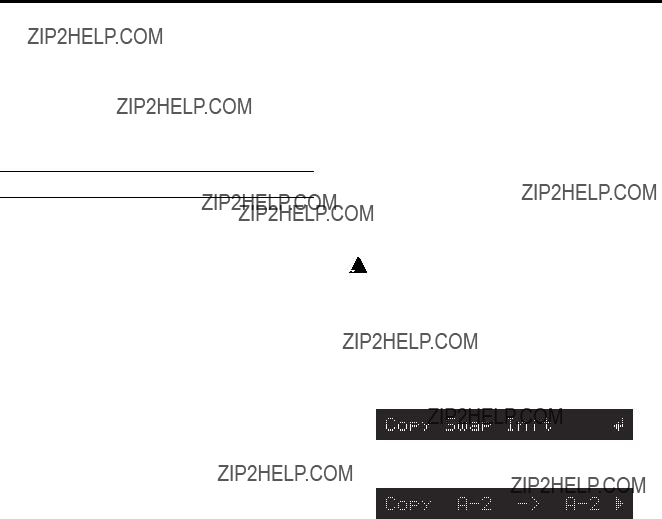
The display will indicate Copy Swap Init.
3.Press the [WRITE/ENTER] key.
???Copy??? will blink in the display.
4.Press the [+] key twice.
???Init Program??? will appear in the left of the display, and ???Program??? will blink.
5.Press the [??] key once.
A speaker icon will appear at the left of the program number.
You can play the keyboard to audition the sound of the program.
6.Use the
7.Press the [WRITE/ENTER] key.
A message will ask you whether you want to initialize the program.
To cancel the procedure, press the [EXIT] key.
8.Press the [WRITE/ENTER] key once again.
When initialization has been completed, the display will indicate Init Completed, and you will return to step 4.
9.Press the [EXIT] key twice to return to the previ- ous mode.
Initializing all programs
Steps
4.Press the [+] key three times.
???Init All Program??? will appear in the left of the display, and ???All Program??? will blink.
16
Basic functions
5.Press the [WRITE/ENTER] key.
A message will ask you whether you want to initialize all the programs.
To cancel the procedure, press the [EXIT] key.
6.Press the [WRITE/ENTER] key once again.
When initialization has been completed, the display will indicate Init Completed, and you will return to step 4.
7.Press the [EXIT] key twice to return to the previ- ous mode.
Initializing the Global parameters
Steps
4.Press the [+] key four times.
???Init Global??? will appear in the left of the display, and ???Global??? will blink.
5.Press the [WRITE/ENTER] key.
A message will ask you whether you want to initialize the Global parameters.
To cancel the procedure, press the [EXIT] key.
6.Press the [WRITE/ENTER] key once again.
When initialization has been completed, the display will indicate Init Completed, and you will return to step 4.
7.Press the [EXIT] key twice to return to the previ- ous mode.
Initializing programs and Global parameters
Steps
4.Press the [+] key five times.
???Init All Data??? will appear in the left of the display, and ???All Data??? will blink.
5.Press the [WRITE/ENTER] key.
A message will ask you whether you want to initialize Program data and Global data.
To cancel the procedure, press the [EXIT] key.
6.Press the [WRITE/ENTER] key once again.
When initialization has been completed, the display will indicate Init Completed, and you will return to step 4.
7.Press the [EXIT] key twice to return to the previ- ous mode.
4. Percussion
When playing the upper keyboard, you can use the front panel PERCUSSION keys and drawbars to add percus- sion.
Percussion adds an attack to the beginning of the note, making the sound more crisp. However when you play legato, percussion will apply only to the
Normal mode
1.In the upper DRAWBAR SELECT section, press the [DRAWBAR 2] key or [PRESET DRAWBAR] key.
or
2.In the PERCUSSION section, press the [ON] key.
The key LED will light.
3.Press the [FAST] key.
When the key LED is lit, the percussion will decay more quickly. When the key LED is dark, the percus- sion will decay more slowly.
4.Press the [SOFT] key.
The volume of the percussion will decrease when the key LED is lit, and will return to normal when the key LED goes dark.
The changes that occur when you press the keys of the PERCUSSION section can be specified in Normal Edit mode Group 3, and stored independently for each program.
For these parameters, you can specify the following.
???The volume for Soft and Normal settings
???The decay speed for Fast and Slow settings
If percussion is not added when you operate the keys of the PERCUSSION section, make sure that the [PRESET DRAWBAR] key is selected. If percussion is still not added, use the following procedure to check the ???DB Preset's Perc??? parameter.
Checking the ???DB Preset's Perc??? parameter
1.Make sure that the display shows the name of a Normal program.
If the display does not show the program name, press the [DISPLAY] key several times.
2.Press the [DISPLAY] key once, and check whether the Percussion icon is shown at the left of UPPER in the display.
If the Percussion icon is displayed, operate the keys of the PERCUSSION section while you play the upper keyboard.
If the Percussion icon is not displayed, proceed to step 3.
17
Basic functions
 Since the ???DB Preset's Perc??? parameter is set inde- pendently for each program, you will have to check each program to see whether percussion can be used for that program.
3.Press the [EDIT] key.
You will enter Normal Edit mode.
4.Press the PROGRAM [2] key, and then press the [??] key twice.
The ???DB Preset's Perc??? parameter will appear.
5.Press the
6.Press the [EXIT] key to return to Normal mode.
7.Now you can assign the PERCUSSION section to the upper keyboard.
EX mode
Regardless of the settings of the DRAWBAR SELECT section, you can also use the front panel PERCUSSION SECTION keys to add percussion to the upper keyboard.
1.In the PERCUSSION section, press the [ON] key.
The key LED will light. The PERCUSSION effect is now on.
2.Press the [FAST] key.
When the key LED is lit, the percussion will decay more quickly. When the key LED is dark, the percus- sion will decay more slowly.
3.Press the [SOFT] key.
The volume of the percussion will decrease when the key LED is lit, and will return to normal when the key LED goes dark.
The values for these percussion controls can be accessed in EX Edit mode Group 3, and may be stored independently for each program.
For these parameters, you can specify the following.
???The volume for Soft and Normal settings
???The decay speed for Fast and Slow settings
EX Percussion in Drawbar 2
If the upper DRAWBAR SELECT section [DRAWBAR 2] key is selected, the percussion can be adjusted by the front panel Drawbar 2 bars as well as by the front panel PERCUSSION section keys.
EX Percussion (the five right bars of Drawbar 2) controls the percussion levels assigned to these bars. For details, refer to ???Using the Drawbar 1 and 2 settings??? (p.13).
2': 16'
1': The footage assigned to EX Drawbar
18
5. Rotary
The ROTARY Speaker section replicates the sound of the classic rotating drum and horn speaker system associated with the tone wheel organ. Controls are available to simulate different amplification and microphone place- ment.
1.In the front panel ROTARY section, press the [ON] key.
The key LED will light.
If when you press the ROTARY section [ON] key, the LED blinks three times and then goes dark, the program's ???Amp Type??? parameter (Group 4 of Normal Edit mode or EX Edit mode) has been set to Pre Amp. With this setting, the rotary speaker effect cannot be obtained. Either select another program, or change the setting of the ???Amp Type??? parameter.

 Even if the ???Amp Type??? parameter is set to Pre Amp, you can select the ROTARY section [STOP] key and [FAST] key. We recommend that you use the [STOP] key and [FAST] key to
2.Use the [FAST] key and [STOP] key to control the rotation of the rotary speaker.
To switch between fast and slow, make the [STOP] key LED go dark, and operate the [FAST] key.
When you press the [FAST] key to make the LED light, the rotary speaker will turn rapidly. When you make the LED go dark, the rotary speaker will turn slowly.
To switch between fast and stopped, make the [STOP] key LED light, and operate the [FAST] key.
When you press the [FAST] key to make the LED light, the rotary speaker will turn rapidly. When you make the LED go dark, the rotary speaker will stop turning.
To switch between slow and stopped, make the [FAST] key LED go dark, and operate the [STOP] key.
When you press the [STOP] key to make the LED light, the rotary speaker will stop turning. When you make the LED go dark, the rotary speaker will turn slowly.
Rotary speaker settings are made in Group 6 of Normal Edit mode or EX Edit mode, and are saved as part of each program.
The following rotary speaker parameters can be adjusted.
???Volume balance between the horn and rotor of the rotary speaker
???Slow and fast rotational speeds of the horn and rotor
???Transition time from slow to fast, and from fast to slow, for the horn and rotor
???Time from when the rotation of the horn and rotor is stopped until it actually comes to a stop, and the time from when rotation is started until it reaches the specified speed
???The distances from the horn and rotor to the mic
???The spread of the sound from the horn and rotor

Basic functions
6. Effects
Reverb
You can use the front panel [REVERB OFFSET] knob to adjust the depth of reverb.
1.While you play, turn the [REVERB OFFSET] knob.
When the knob is in the center position, the reverb depth will be as specified by the program.
Reverb settings are made in Group 5 of Normal Edit mode and EX Edit mode, and are saved as part of each program.
The following reverb parameters can be adjusted.
???Reverb type
???Reverb time
???Reverb amount
???Reverb routing
Vibrato and chorus
You can use the front panel VIBRATO/CHORUS section to apply vibrato or chorus to the sound.
1.While you play, use the VIBRATO/CHORUS section [UPPER] key or [LOWER] key to select the keyboard(s) to which the effect will be applied.
2.Use the [VIBRATO/CHORUS] knob to select vibrato or chorus.
Overdrive
You can use the front panel [EXPRESSION/OVER- DRIVE] knob to adjust the amount of overdrive. This will also affect the volume.
1.While you play, turn the [EXPRESSION/OVER- DRIVE] knob.
This will adjust the output level of the tone generator, changing the input level of the internal amp simula- tion.
By using this in conjunction with the ???Amp Gain??? parameter (p.26) in Group 4 of Normal Edit mode or EX Edit mode, you can make further adjustments to the overdrive effect.
7. Saving your data
Program parameter settings and Global parameter settings of the
Writing to internal memory
Writing a program
A program that you created by editing the parameters in either of the Edit modes can be saved in internal memory. This is referred to as ???writing a program.??? If you want the program you edited to be preserved even when the power is turned off, you must write it into memory.
When you select a program, the program data is called into an internal edit buffer.
When you edit program parameters in Normal Edit mode or EX Edit mode, you are making changes to the data in the edit buffer. When you make changes to this data, an ??? ??? will appear between the program number and program name.
Since your editing will only affect the data in the edit buffer, you must write this data into internal memory if you want to keep it.
 If you select another program before writing the edited program, new data will be called into the edit buffer, and your changes will be lost. The data in the edit buffer will also be lost when you turn off the power. If this occurs, the data prior to your editing will be recalled the next time the power is turned on.
Writing procedure
1.Make sure that you are in Normal mode or EX mode, and that the Enter icon is not displayed. Then press the [WRITE/ENTER] key.
The left side of the display will indicate ???WRITE.??? The
2.If you want to change the writing destination, use the
By playing the keyboard, you can audition the sound of the program marked by the Speaker icon in the display. You can use the [??? ][??] keys to move the Speaker icon, so that you can audition the writing- source and

 When the Speaker icon is displayed, you can press and hold the [DISPLAY] key to view the name of the program indicated by the icon.

 At this time, you can press the [GLOBAL] key to switch to writing the Global parameters. To return to writing the program, press the [EDIT] key.
3.Press the [WRITE/ENTER] key.
A message will ask whether it is OK to write the program.
If you decide to cancel, press the [EXIT] key.
19
Basic functions
4.Press the [WRITE/ENTER] key.
When the data has been written, the display will indicate Write Completed.
Writing the Global parameters
Settings that affect all programs in common, such as MIDI settings, are made in Global mode.
When you turn on the power, the Global mode data will be called into the internal Global mode memory area.
When you edit a parameter in Global mode, the data in this memory area will change.
If you want the edited data to be saved in internal memory, you must write it.
 If you turn off the power before writing the Global parameters, the edited data in the memory area will be lost. If this occurs, the data prior to your editing will be recalled the next time the power is turned on.
Writing procedure
1.Make sure that you are in Global mode, and that the Enter icon is not displayed. Then press the [WRITE/ENTER] key.
The left side of the display will indicate WRITE.
GLOBAL.
 At this time you can press the [EDIT] key to write program data. To return to the writing the Global parameters, press the [GLOBAL] key.
2.Press the [WRITE/ENTER] key.
A message will ask you whether it is OK to write. If you decide to cancel, press the [EXIT] key.
3.Press the [WRITE/ENTER] key.
When the data has been written, the display will indicate Write Completed.
MIDI data dump
The programs and global settings in internal memory can be transmitted as MIDI exclusive data, and saved on a connected external device such as a data filer. For details, refer to ???MIDI data dump??? (p.37).
8. Editing
You can edit the tone or name of the selected program. When editing a program, it is a good idea to start by selecting the program that is closest to what you have in mind, and make your changes from there.
This section explains some simple ways to edit.
 If you select another program or turn off the power before writing your edited settings, the changes will be lost. For details, refer to ???Writing a program??? (p.19).
Editing the sound
The
As an example, here's how to edit the parameters of group 1.
1.Press the [EDIT] key to enter either Normal Edit mode or EX Edit mode.
2.Press the PROGRAM [1] key, and then press the [??] key once to access the ???Wheel Type??? param- eter.
This selects the type of tone wheel.
The tone wheel is the mechanism that produces the pitches used to create the sound.
3.Use the
Vintage includes leakage noise. This is noise caused by signal leakage from the tone wheel, and is a characteristic part of the sound of a tone wheel organ. Clean contains no leakage noise.
4.Press the [??] key once to access the ???DB
LevelCurve??? parameter, and use the
This adjusts the tone of the drawbars.
Bright produces a brighter sound as you play higher on the keyboard, and Mellow produces a more mellow sound in the upper octaves.
5.Press the [??] key once to access the ???Over Tone
Level??? parameter, and use the
This parameter adjusts the overtone level of the tone wheel. Higher settings will produce a greater amount of overtones.
6.Press the [??] key once to access the ???Leakage
Level??? parameter, and use the
This adjusts the leakage noise. Higher settings will increase the volume of the leakage noise.
7.Press the [??] key once to access the ???Noise
Level??? parameter, and use the
This adjusts the noise that will occur regardless of whether notes are being played. Higher settings will increase the volume of the noise.
8.Press the [??] key once to access the ???On Click
Level??? parameter, and use the
20
Basic functions
This parameter simulates the noise that occurs when a key is pressed. Here you can adjust the volume of that noise. Higher settings will increase the noise volume.
9.Press the [??] key once to access the ???Off Click
Level??? parameter, and use the
This parameter simulates the noise that occurs when a key is released. Here you can adjust the volume of that noise. Higher settings will increase the noise volume.
10.Press the [WRITE/ENTER] key to write the settings into internal memory.
For details, refer to ???Writing a program??? (p.19).
Other parameters
The
If you want to make detailed adjustments to the sound of a program, you can edit the following parameters in Normal Edit mode or EX Edit mode.
???Percussion settings: Group 3 (p.25)
???Amp simulator settings: Group 4 (p.26)
???Reverb settings: Group 5 (p.26)
???Rotary speaker settings: Group 6 (p.26)
???Modulation wheel and pedal controller settings: Group 7 (p.27)
Editing the drawbar parameters
When the DRAWBAR SELECT section [DRAWBAR PRESET] key is pressed, the drawbars will sound at the levels saved with the current program. These settings are saved individually for each program.
Normal mode
If the [DRAWBAR PRESET] key is pressed in both upper and lower DRAWBAR SELECT sections, the ???UPPER??? parameters will be used when you play the upper keyboard, and the ???LOWER??? parameters will be used when you play the lower keyboard.
If you want to edit these settings, use the following procedure.
1.Select a program in Normal mode.
2.Press the [EDIT] key.
You will enter Normal Edit mode.
3.Press the PROGRAM [2] key.
The left side of the display will indicate UPPER, and to the right of this the ???UPPER??? parameter settings will be displayed.
If you are unable to adjust the ???UPPER??? parameter settings, make sure that the DRAWBAR SELECT section [DRAWBAR PRESET] key is selected.
If the [DRAWBAR PRESET] key is not selected, its LED will begin to blink.
4.Move the bars of the Drawbar 1 or Drawbar 2 sections (you may use either) to adjust the draw- bar parameters.
Any bar you move will input a new value for that parameter, and the display will change accordingly.
5.Press the [??] key once to display the ???LOWER??? parameters.
6.Move the bars of the Drawbar 1 or Drawbar 2 sections to adjust the drawbar parameters.
7.Press the [WRITE/ENTER] key to write the settings into internal memory.
For details, refer to ???Writing a program??? (p.19).
EX mode
In EX mode, the lower keyboard will play the ???EX LOWER??? parameter settings that are preset in the pro- gram, regardless of the current setting in the DRAWBAR SELECT section.
To edit these settings, use the following procedure.
1.Select a program in EX mode.
2.Press the [EDIT] key.
You will enter EX Edit mode.
3.Press the PROGRAM [2] key, and then press the [??] key once.
The ???EX LOWER??? parameters will be displayed.
4.Use the [??? ][??] keys to select a bar.
You can make settings for the three bars 16', 8', and 4'.
16' 8' 4'
5.Use the
The display will show the value as you adjust it.
6.Press the [WRITE/ENTER] key to write the settings into internal memory. For details, refer to ???Writing a program??? (p.19).
Copying drawbar parameters
The front panel Drawbar 1 or Drawbar 2 settings can be copied directly to the ???UPPER??? or ???LOWER??? parameters of a Normal program, or to the ???EX Drawbar Level??? parameters of an EX program.
As an example, here's how you can select a Normal program, use the front panel Drawbar 1 bars to create a sound, and then copy the settings to the ???UPPER??? parameters of the program.
1.Select a program in Normal mode.
2.In the upper DRAWBAR SELECT section, press the [DRAWBAR 1] key.
3.While playing the keyboard, use the front panel Drawbar 1 bars to create the desired sound.
21
Basic functions
4.In the upper DRAWBAR SELECT section, hold down the [DRAWBAR 1] key and press the [DRAW- BAR PRESET] key.
The Drawbar 1 settings will be copied to the ???UPPER??? parameters, and an ??? ??? will appear between the program number and program name.
5.Press the [WRITE/ENTER] key to write the settings into internal memory.
For details, refer to ???Writing a program??? (p.19).

 The upper DRAWBAR SELECT section can be used to copy drawbar parameters in EX mode as well. Create the sound in the upper keyboard, then hold down the upper [DRAWBAR 1] or [DRAWBAR 2] key, and press the [DRAWBAR PRESET] key.
Copying a program
This is convenient when you want to create several variations of a program by making small changes to the parameter settings.
1.Press the [GLOBAL] key to enter the Global mode.
2.Press the PROGRAM [7] key, and then press the [??] key once.
The display will indicate Copy Swap Init.
3.Press the [WRITE/ENTER] key.
In the display, ???Copy??? will blink, and the copy source and copy destination program numbers will appear at the right.
7.Press the [WRITE/ENTER] key.
A message will ask you to confirm the copy. If you decide to cancel, press the [EXIT] key.
8.Press the [WRITE/ENTER] key once again.
When the program has been copied, the display will indicate Copy Completed.
Swapping two programs
This operation exchanges two programs. This is conve- nient when you want to rearrange the order of the programs.
1.Press the [GLOBAL] key to enter the Global mode.
2.Press the PROGRAM [7] key, and then press the [??] key once.
The display will indicate Copy Swap Init.
3.Press the [WRITE/ENTER] key, and then press the
[+] key once.
???Swap??? will blink in the display. The
4.Press the [??] key once, and the Speaker icon will appear at the left of the
You can play the keyboard to hear the sound of the program.
5.If you want to change the swap source, use the
6.If you want to change the swap destination, press the [??] key once, and then use the
7.Press the [WRITE/ENTER] key.
A message will ask you to confirm the swap. If you decide to cancel, press the [EXIT] key.
8.Press the [WRITE/ENTER] key once again.
When the swap is completed, the display will indicate
Swap Completed.
4.Press the [??] key once, and the Speaker icon will appear at the left of the
You can play the keyboard to hear the sound of the program.
5.To change the
6.To change the
The Speaker icon will appear at the left of the copy- destination program number.
Editing the name of a program
1.Press the [EDIT] key to enter Normal Edit mode or EX Edit mode.
2.Press the PROGRAM [8] key.
???Rename??? will appear in the left of the display, and the program name will be displayed in square brack- ets [ ].
3.Use the [??? ] [??] keys to select the character that you want to change.
22

Basic functions
4.Use the
You can assign a program name of up to 12 characters.
5.Press the [WRITE/ENTER] key to write the settings into internal memory.
For details, refer to ???Writing a program??? (p.19).
23

1. Normal Edit mode / EX Edit mode
In Normal Edit mode or EX Edit mode, you use the PROGRAM
Group 1: Basic Character
Specifies the output level, tone wheel noise, click level etc.
Group 2: Drawbar
Specifies the drawbar levels and EX drawbar type.
 The parameters that are displayed will differ be- tween Normal Edit mode and EX Edit mode.
Group 3: Percussion
Specifies how the
Group 4: Amp
Specifies amp settings.
Group 5: Reverb
Adjusts reverb settings.
Group 6: Rotary effect
Specifies rotary speaker settings.
Group 7: Controller
Specifies settings for the modulation wheel, and specify the functions of the ASSIGNABLE PEDAL/ SW jacks.
Group 8: Program Name
Edits the program name.
Group 1: Basic Character
Sets the output level of the program.
Selects the type of tone wheel.
Vintage: A tone wheel that includes leakage noise.
Clean: A tone wheel that does not include leakage noise.
Selects the tone.
The tone will change as the volume balance of the drawbars is adjusted.
Bright: A bright tone.
Mellow: A mellow tone.
Specifies the overtone level of the tone wheel.
Specifies the level of the leakage noise.
Specifies the amount of noise that will occur regardless of whether notes are played. This noise will include leakage noise, and its amount will depend on the level specified by the ???Leakage Level??? parameter.
Specifies the level of the click noise at
Specifies the level of the click noise at
Group 2: Drawbar
This is displayed in Normal Edit mode.
Specifies the volume of the footage used when you play the upper keyboard in Normal mode.
To change these settings, press the [DRAWBAR PRESET] key of the upper DRAWBAR SELECT section in Normal mode. When you move the Drawbar 1 or 2 bars of the front panel, the volume of the corresponding footage will change. If you pull a bar out all the way, its level will be 8.
 In Normal mode when the program name is dis- played, pressing the [DISPLAY] key once will let you view these settings in the display.
24
Parameters
This is displayed in Normal Edit mode.
Here you can specify the volume of the footage used when you play the lower keyboard in Normal mode.
To change these settings, press the [DRAWBAR PRESET] key of the lower DRAWBAR SELECT section in Normal mode. When you move the Drawbar 1 or 2 bars of the front panel, the volume of the corresponding footage will change. If you pull a bar out all the way, its level will be 8.
 In Normal mode when the program name is dis- played, pressing the [DISPLAY] key once will let you view these settings in the display.
DB Preset's Perc (Drawbar Preset Percussion)
[Dis, Ena]
This is displayed in Normal Edit mode.
This setting specifies whether the keys of the PERCUS- SION section can be used when you play the upper keyboard in Normal mode.
Dis (Disable): Operating the PERCUSSION section keys will have no effect.
Ena (Enable): The PERCUSSION section keys will have their usual effect.
 In Normal mode when the program name is dis- played, pressing the [DISPLAY] key once will let you view these settings in the display. If this setting is set to Ena (enable), the Percussion icon will appear at the left of the UPPER display.
This is displayed in EX Edit mode.
Drawbar 1
EX Drawbar and EX Percussion of Drawbar 2
Here you can specify the footage and percussion volume used when you play the upper keyboard in EX Edit mode.
To edit the values, press the [DRAWBAR PRESET] key in the upper DRAWBAR SELECT section while in EX Edit mode. When you move the front panel Drawbar 1 or 2 bars, the corresponding footage or percussion volume will change. The value will be 8 when a bar is pulled all the way out.
For details on what is assigned to each bar, refer to ???Using the Drawbar 1 and 2 settings??? (p.13).
 In EX mode, pressing the [DISPLAY] key once while the program name is displayed will display the current Drawbar 1 and EX Drawbar (Drawbar 2) values. If you then press the [DISPLAY] key once again, the EX Percussion (Drawbar 2) values will be displayed.
This is displayed in EX Edit mode.
These settings specify the footage volumes used when you play the lower keyboard in EX mode.
You can make settings for the three drawbars 16', 8', and 4'. For details on how to make these settings, refer to ???EX mode??? (p.21).
This is displayed in the EX Edit mode.
By selecting the type, you can specify the pitches that are assigned to the EX Drawbars (Encoder 2).
The pitches for each of these types are specified by the Global mode Group 6 ???Ex Drawbar Type
Group 3: Percussion
This sets the volume of the percussion when the [SOFT] key of the PERCUSSION section is at the normal setting (key LED dark).
Perc Soft Offset (Percussion Soft Level Offset) [0...99]
This sets the volume of the percussion when the [SOFT] key of the PERCUSSION section is at the soft setting (key LED lit). This setting determines how much the volume will be lowered from the value specified by the ???Perc Nrml Level??? parameter.
Normal Perc DB ATT (Normal Percussion Drawbar
This decreases the level of the sound created by the Drawbar 2 bars or the "UPPER " parameters when the percussion is set to normal (the [SOFT] key is dark). This allows the percussion effect to become more pronounced, without increasing the overall volume.
This sets the decay speed when the [FAST] key of the PERCUSSION section is at the fast setting (key LED lit).
This sets the decay speed when the [FAST] key of the PERCUSSION section is at the slow setting (key LED dark). This setting will determine how much the speed is slowed from the value specified by the ???Perc Fast Decay??? parameter.
25
Parameters
Group 4: Amp
here you can select the amp type.
Type 1: This is a conventional organ power amp. It produces a mild and fat sound.
Type 2: Compared to Type 1, this emphasizes the high range, and produces a more uncolored sound.
Pre Amp: Use a pre amp. This is the sound of the organ's
 When Type 1 or Type 2 are selected: When the front panel ROTARY [ON] key is used to turn on the rotary speaker, the effect of the rotary speaker will be simulated. When this is turned off, a conventional speaker will be simulated.
When Pre Amp is selected: The power amp and rotary speaker will not be used, and the sound will be as if it were taken from the preamp
When the ???Amp Type??? parameter is set to Type 1 or Type 2, this turns the amp simulator function on or off.
Adjusts the gain (amplification) when the ???Amp Type??? parameter is set to Type 1 or Type 2.
With high settings of this value, the sound will distort more severely when the expression/overdrive is raised.
 This setting will not apply if the ???Amp Type??? parameter is set to Pre Amp.
Adjusts the high frequency level of the amp selected by the ???Amp Type??? parameter.
Adjusts the
Adjusts the low frequency level of the amp selected by the ???Amp Type??? parameter.
Group 5: Reverb
 The range in which the reverb time can be adjusted will depend on your selection for the ???Reverb Type??? parameter.
Specifies the amount of reverb signal that is mixed with the original sound.
Rev Routing (Reverb Routing)
Selects whether the reverb will be applied before the rotary speaker or after it.
 This setting will not be used if the ???Amp Type??? parameter is set to Pre Amp.
Group 6: Rotary Effect
 These settings will not be used if the ???Amp Type??? parameter is set to Pre Amp.
Horn: 0 Rotor: 100 (Rotary Horn/Rotor Balance)
[0:100...100:0]
Adjuststhe volume balance between the horn and rotor of the rotary speaker.
Specifies the rotational speed of the horn during slow rotation.
Specifies the rotational speed of the horn during fast rotation.
Specifies the rotational speed of the rotor during slow rotation.
Specifies the rotational speed of the rotor during fast rotation.
Specifies the time over which the horn will change from slow to fast rotation.
Specifies the time over which the horn will change from fast to slow rotation.
Specifies the time it will take for the horn to actually come to rest after rotation is switched off.
Specifies the time it will take for the horn to reach the specified speed after rotation is switched on.
26
Parameters
Adjusts the time over which the rotor rotation changes from slow to fast.
Rotor Down Transit (Rotor Down Transition) [0...99]
Adjusts the time over which the rotor rotation changes from fast to slow.
Adjusts the time over which the rotor rotation actually comes to a stop after you stop the rotation.
Adjusts the time over which the rotor reaches the speci- fied speed after it begins to rotate.
When Rotary is on
Adjusts the distance between the horn and the mic.
Adjusts the distance between the ???simulated mics??? to increase the stereo field.
Adjusts the distance between the rotor and the mic.
Adjusts the distance between the ???simulated mics??? to increase the stereo field.
Mic Spread
Rotor
Group 7: Controller
Mod Wheel (Modulation Wheel)
[No Assign...ExLowLevl]
Select the parameter that will be controlled by the front panel modulation wheel.
If this is set to other than No Assign, Rtry FAST, or Wheel Brake, the result of moving the wheel will depend on the setting of the ???Mod Wheel Range.???
No Assign: Nothing will be controlled.
Click Level: Control the ???On Click Level??? and ???Off Click Level??? parameters (Group 1).
Perc Level (Percussion Level): Control the ???Perc Nrml Level??? parameter (Group 3).
Perc Decay (Percussion Decay): Control the ???Perc Fast
Decay??? parameter (Group 3).
Rtry FAST (Rotary Fast/Slow): Control the front panel ROTARY [FAST] key. The modulation wheel will function as a switch, and will select Fast when the wheel is moved toward yourself, and Slow when moved away from yourself.
Rtry Speed (Rotary Speed): Control the ???Horn Fast Speed,??? ???Horn Slow Speed,??? ???Rotary Fast Speed,??? and ???Rotary Slow Speed??? parameters (Group 6).
Wheel Brake: Control the ???Wheel Brake??? parameter (Global mode Group 7). The modulation wheel will function as a switch, and will turn on the wheel brake effect when the modulation wheel is moved away from yourself, and will turn off the wheel brake effect when moved toward yourself.
ExLowrLevl (EX Lower Level): Control the ???EX LOWER???
parameter (Group 2).
Mod Wheel Range (Modulation Wheel Range)
When the ???Mod Wheel??? parameter is set to other than No Assign, Rtry FAST, or Wheel Brake, the range of the effect controlled by operating the modulation wheel can be adjusted from a maximum of 0 to a maximum of 99. When you move the modulation wheel fully toward yourself, the parameter being controlled will be at its own original setting.
When you move the modulation wheel fully away from yourself, the value you specify here will be added to the original value of the parameter being controlled. How- ever, the total value is limited to a range of 0 to 99.
If the ???Perc Nrml Level??? parameter is set to 50, the following Mod Wheel Range settings will allow the position of the modulation wheel to change the percus- sion level as follows.
+20: The percussion level will be 50 when the modulation wheel is fully toward yourself, and 70 when fully away from yourself.
If the ???Perc Nrml Level??? parameter is set to 99, the following Mod Wheel Range settings will allow the position of the modulation wheel to change the percus- sion level as follows.
+99: The percussion level will be 99 when the modulation wheel is fully toward yourself, and 99 when fully away from yourself (since the controllable range is
27

Parameters
Hold Uppr Ctrl (Hold Upper Controller)
[Off, Pedal 1/(Pdl1)*, Pedal 2/(Pdl 2)*]
This is displayed in Normal Edit mode.
Pedal 1: A pedal switch etc. connected to the rear panel ASSIGNABLE PEDAL/SW 1 jack will switch Hold on/off for the notes played on the keyboard that controls the UPPER tone generator.
Pedal 2: A pedal switch etc. connected to the rear panel ASSIGNABLE PEDAL/SW 2 jack will perform the above operation.
Off: No function.
Hold Lowr Ctrl (Hold Lower Controller)
[Off, Pedal 1/(Pdl1)*, Pedal 2/(Pdl 2)*]
This is displayed in Normal Edit mode.
Pedal 1: A pedal switch etc. connected to the rear panel ASSIGNABLE PEDAL/SW 1 jack will switch Hold on/off for the notes played on the keyboard that controls the LOWER tone generator.
Pedal 2: A pedal switch etc. connected to the rear panel ASSIGNABLE PEDAL/SW 2 jack will perform the above operation.
Off: No function.
Wheel Brk Ctrl (Wheel Brake Controller)
[Off, Pedal 1/(Pdl1)*, Pedal 2/(Pdl 2)*]
This is displayed in Normal Edit mode.
Pedal 1: A pedal switch etc. connected to the rear panel ASSIGNABLE PEDAL/SW 1 jack will switch the ???Wheel Brake??? parameter (Global mode Group 7) on/off.
Pedal 2: A pedal switch etc. connected to the rear panel ASSIGNABLE PEDAL/SW 2 jack will perform the above operation.
Off: No function.
Wheel Brk Pedal (Wheel Brake Pedal Mode)
[Momnt, Alter]
Select the on/off operation of the pedal switch etc. connected to the rear panel ASSIGNABLE PEDAL/SW 1 or 2 jack.
Momnt: The pitch will gradually fall as long as you continue pressing the pedal switch. When you release the pedal switch, the pitch will gradually rise to the normal state.
Alter: The pitch will begin falling once you press the pedal switch. When you press it once again, the pitch will gradually rise to the normal state.
Rtry FAST Ctrl (Rotary FAST Controller)
[Off, Pedal 1/(Pdl1)*, Pedal 2/(Pdl 2)*]
Pedal 1: A pedal switch etc. connected to the rear panel ASSIGNABLE PEDAL/SW 1 jack will turn the ROTARY [FAST] key on/off.
Pedal 2: A pedal switch etc. connected to the rear panel ASSIGNABLE PEDAL/SW 2 jack will perform the above operation.
Off: No function.
Rtry FAST Pedal (Rotary FAST Pedal Mode)
[Momnt, Alter]
Select the on/off operation of the pedal switch etc. connected to the rear panel ASSIGNABLE PEDAL/SW 1 or 2 jack. The pedal switch will have the same function as pressing the front panel ROTARY [FAST] key.
Momnt: The rotary speed will gradually increase as long as you continue pressing the pedal switch, until it reaches the speed specified by the Group 6 ???Rotor Fast Speed??? parameter. When you release the pedal switch, the rotary speed will gradually decrease until it reaches the speed specified by the Group 6 ???Rotor Slow Speed??? parameter. Alter: Once you press the pedal switch, the rotary speed will gradually increase until it reaches the speed specified by the Group 6 ???Rotor Fast Speed??? parameter. When you press the pedal switch once again, the rotary speed will gradually decrease until it reaches the speed specified by the Group 6 ???Rotor Slow Speed??? parameter.
Rtry STOP Ctrl (Rotary STOP Controller)
[Off, Pedal 1/(Pdl1)*, Pedal 2/(Pdl 2)*]
Pedal 1: A pedal switch etc. connected to the rear panel ASSIGNABLE PEDAL/SW 1 jack will turn the ROTARY [STOP] key on/off.
Pedal 2: A pedal switch etc. connected to the rear panel ASSIGNABLE PEDAL/SW 2 jack will perform the above operation.
Off: No function.
Rtry STOP Pedal (Rotary STOP Pedal Mode)
[Momnt, Alter]
Select the on/off operation of the pedal switch etc. connected to the rear panel ASSIGNABLE PEDAL/SW 1 or 2 jack. The pedal switch will have the same function as pressing the front panel ROTARY [STOP] key.
Momnt: The rotary speed will gradually slow down and then stop as long as you continue pressing the pedal switch.
Alter: Once you press the pedal switch, the rotary speed will gradually slow down and then stop.
Amp Gain Ctrl (Amp Gain Controller)
[Off, Pedal 1/(Pdl 1)*, Pedal 2/(Pdl 2)*]
Pedal 1: An expression pedal etc. connected to the rear panel ASSIGNABLE PEDAL/SW 1 jack will control the Group 4 ???Amp Gain??? parameter of Normal Edit mode and EX Edit mode.
Pedal 2: An expression pedal etc. connected to the rear panel ASSIGNABLE PEDAL/SW 2 jack will perform the above operation.
Off: No function.

Parameters
Amp Gain Ctrl Min (Amp Gain Control Minimum)
[0...99]
Specify the minimum setting of the Normal Edit mode and EX Edit mode Group 4 ???Amp Gain??? parameter. This will be the gain when the expression pedal etc. specified by the ???Amp Gain Ctrl??? parameter is in the minimum position.
Amp Gain Ctrl Max (Amp Gain Control Maximum)
[0...99]
Specify the maximum setting of the Normal Edit mode and EX Edit mode Group 4 ???Amp Gain??? parameter. This will be the gain when the expression pedal etc. specified by the ???Amp Gain Ctrl??? parameter is in the maximum position.
Rev Mix Ctrl (Reverb Mix Controller)
[Off, Pedal 1/(Pdl 1)*, Pedal 2/(Pdl 2)*]
Pedal 1: An expression pedal etc. connected to the rear panel ASSIGNABLE PEDAL/SW 1 jack will control the Group 5 ???Reverb Mix Level??? parameter of Normal Edit mode and EX Edit mode.
Pedal 2: An expression pedal etc. connected to the rear panel ASSIGNABLE PEDAL/SW 2 jack will perform the above operation.
Off: No function.
Rev Mix Ctrl Min (Reverb Mix Control Minimum)
[0...99]
Specify the minimum setting of the Normal Edit mode and EX Edit mode Group 5 ???Reverb Mix??? parameter. This will be the reverb mix level when the expression pedal etc. specified by the ???Reverb Mix Ctrl??? parameter is in the minimum position.
Rev Mix Ctrl Max (Reverb Mix Control Maximum)
[0...99]
Specify the maximum setting of the Normal Edit mode and EX Edit mode Group 5 ???Reverb Mix??? parameter. This will be the reverb mix level when the expression pedal etc. specified by the ???Reverb Mix Ctrl??? parameter is in the maximum position.
Group 8: Program Name
Rename
Here you can modify the name. You can use up to twelve characters.
Use the [??? ][??] keys to select the character that you wish to change, and use the

Parameters
2. Global mode
In Global mode, you can press the PROGRAM
Group 1: Basic
Specifies the master tuning, the expression pedal function, the pedal switch function, the pitch bend range, and the keyboard triggering type etc.
Group 2: MIDI Channel
Specifies the MIDI channels.
Group 3: MIDI Parameters
Set MIDI filtering and Local on/off.
Group 4: MIDI CC#1
Specifies the MIDI control change numbers that will be used to transmit and receive drawbar settings.
Group 5: MIDI CC#2
Specifies the MIDI control change numbers that will be assigned to the front panel keys and wheels, and to connected pedals.
Group 6: ExDrawbar Set
Specifies the EX drawbar types.
Group 7: Utility
Copy, swap, or initialize programs, execute a data dump, make settings for the DRAWBAR SELECT section, calibrate a connected pedal, and adjust the settings for the wheel break function.
Group 8: DEMO
Use this parameter to play the demo songs.
Group 1: Basic
Adjusts the overall pitch in 0.2 Hz steps, with A4 (middle A) as the reference pitch.
Transposes the pitch in semitone steps over a range of +/- 1 octave.
Exp Minimum Level (Expression Minimum Level)
[0...30]
Specifies the minimum level when the expression pedal etc. is operated. This will be the volume when the control- ler selected by ???Exp Control??? is in the minimum position.
Exp Ctrl (Expression Controller)
[Both Indiv, Knob Only, Pedal Only, Both Multi]
Both Indiv: The [EXPRESSION/OVERDRIVE] knob and the expression pedal connected to the EXPRESSION PEDAL jack will both control the volume. These two will function simultaneously.
Knob Only: The [EXPRESSION/OVERDRIVE] knob will control the volume.
Pedal Only: The expression pedal connected to the EXPRESSION PEDAL jack will control the volume. Both Multi: The [EXPRESSION/OVERDRIVE] knob and the expression pedal connected to the EXPRESSION PEDAL jack will both control the volume. The [EXPRES- SION/OVERDRIVE] knob will set the maximum level of the range controlled by the expression pedal.
Prog Chng (Program Change) [All Params, Int. Params]
Specifies whether the settings of the front panel ROTARY section, VIBRATO/CHORUS section, and PERCUSSION setting will also change when you switch programs.
All Params (All Parameters): When you switch programs, the settings of the front panel keys will also change according to the settings of the selected program.
Int. Params (Internal Parameters): The settings of the front panel keys will not change when you switch programs.
Specifies the range (in semitone steps) that the pitch can change when the pitch wheel is operated or when MIDI pitch bend change messages are received.
Selects either Slow or Fast as the speed with which the wheel brake will stop or resume rotation.
Shallow: When a note is played, the sound will begin or end at the first contact (shallow position). This allows the keys to respond rapidly to your playing, as on traditional combo organs. However, the ???bounce??? when a key returns may produce a brief sound.
Deep: When a note is played, the sound will begin or end at the second contact (deep position). This produces the typical playing response of most electronic keyboard instruments.
30
Parameters
Prog Up Ctrl (Program Up Controller)
[Off, Pedal 1/(Pdl 1), Pedal 2/(Pdl 2)]
Pedal 1: The pedal switch connected to the rear panel ASSIGNABLE PEDAL/SW 1 jack will switch programs. Each time you operate the pedal switch, the program number will be increased by 1.
Pedal 2: The pedal switch connected to the rear panel ASSIGNABLE PEDAL/SW 2 jack will perform the function described above.
Off: No function
(Pdl 1), (Pdl 2): Indicates that this pedal switch is already selected for the following ???Prog Down Ctrl??? parameter. Please select a different pedal switch.
 If the same pedal switch is selected for a parameter in Normal Edit mode or EX Edit mode as well as for this Global parameter, this Prog Up Ctrl setting will be used, and the setting in Normal Edit mode or EX Edit mode will be ignored.
Prog Down Ctrl (Program Down Controller)
[Off, Pedal 1/(Pdl 1), Pedal 2/(Pdl 2)]
Pedal 1: The pedal switch connected to the rear panel ASSIGNABLE PEDAL/SW 1 jack will switch programs. Each time you operate the pedal switch, the program number will be decreased by 1.
Pedal 2: The pedal switch connected to the rear panel ASSIGNABLE PEDAL/SW 2 jack will perform the function described above.
Off: No function
(Pdl 1), (Pdl 2): Indicates that this pedal switch is already selected for the above ???Prog Up Ctrl??? parameter. Please select a different pedal switch.
 If the same pedal switch is selected for a parameter in Normal Edit mode or EX Edit mode as well as for this Global parameter, this Prog Down Ctrl setting will be used, and the setting in Normal Edit mode or EX Edit mode will be ignored.
Set these parameters to match the polarity of the pedal switches connected to the rear panel ASSIGNABLE PEDAL/SW 1 and 2 jacks. If these settings do not match the actual polarity of the pedal switches, the pedal switches will not operate correctly.
For example, the separately sold
Group 2: MIDI Channel
Specifies the global MIDI channel that will be used to transmit and receive MIDI. (The factory setting is 1.)
MIDI Upper Rx ch (MIDI Upper Receive Channel) [1...16, Off]
Specifies the MIDI channel on which the UPPER key- board will receive MIDI note messages. (The factory setting is channel 1.)
MIDI Upper Tx ch (MIDI Upper Transmit Channel) [1...16, Off]
Specifies the channel on which the UPPER keyboard will transmit MIDI note messages with a fixed velocity value. (The factory setting is channel 1.) The velocity value is set by ???MIDI Fixed Velcty.???
MIDI Upper 2nd ch (MIDI Upper 2nd Transmit
Specifies the channel on which the UPPER keyboard will transmit MIDI note messages with a variable velocity. (The factory setting is Off.)
Off: Messages will not be transmitted. Be sure to turn this Off unless you are using a MIDI sound module that requires variable velocity (such as a piano module).
 If you specify a MIDI channel for this parameter and are using a MIDI sound module etc. connected to the
MIDI Lower Rx ch (MIDI Lower Receive Channel) [1...16]
Specifies the MIDI channel on which the LOWER key- board will receive MIDI note messages. (The factory setting is 2.)
MIDI Lower Tx ch (MIDI Lower Transmit Channel) [1...16, Off]
Specifies the channel on which the LOWER keyboard will transmit MIDI note messages with a fixed velocity value. (The factory setting is channel 2.) The velocity value is set by ???MIDI Fixed Velcty.???
MIDI Lower 2nd ch (MIDI Lower 2nd Transmit
Specifies the channel on which the LOWER keyboard will transmit MIDI note messages with a variable velocity. (The factory setting is Off.)
Off: Messages will not be transmitted. Be sure to turn this Off unless you are using a MIDI sound module that requires variable velocity (such as a piano module).
 If you specify a MIDI channel for this parameter and are using a MIDI sound module etc. connected to the
Group 3: MIDI Parameters
Specifies the velocity value of the MIDI note messages that are transmitted with fixed velocity. (The factory setting is 80.)
MIDI Rx Prg Chng (MIDI Receive Program Change)
[Dis, Ena]
Dis (Disable): MIDI program changes received on the global MIDI channel will be ignored.
Ena (Enable): The
MIDI Prog Mapper (MIDI Program Mapper) [Dis, Ena]
Dis (Disable): The program mapper will not be used when transmitting or receiving MIDI program changes. Ena (Enable): The program mapper will be used when transmitting or receiving MIDI program changes. (The factory setting is Ena.)
MIDI Rx Sys Exc (MIDI Receive System Exclusive)
[Dis, Ena]
Dis (Disable): Incoming system exclusive data will be ignored. (The factory setting is Dis.)
Ena (Enable): Incoming system exclusive data will be received.
31

Parameters
MIDI Rx C. Change (MIDI Receive Control Change)
[Dis, Ena]
Dis (Disable): Incoming MIDI control changes will be ignored.
Ena (Enable): Incoming MIDI control changes will be received. (The factory setting is Ena.)
MIDI Tx C. Change (MIDI Transmit Control Change)
[Dis, Ena]
Dis (Disable): MIDI control changes will not be transmit- ted.
Ena (Enable): MIDI control changes will be transmitted. (The factory setting is Ena.)
Turns local control on/off. (The factory setting is On.) Off: The keyboard will be internally disconnected from the tone generator section. Select this setting when you want to use the keyboard and controllers of the
Group 4: MIDI CC# 1
CC# Upper DB Sel (MIDI CC# Upper Drawbar Select) [1...31, 33...95, Off]
Specifies the MIDI control change number that will be used to transmit and receive the UPPER setting of the DRAWBAR SELECT section. (The factory setting is 79.)
CC# Lower DB Sel (MIDI CC# Lower Drawbar Select) [1...31, 33...95, Off]
Specifies the MIDI control change number that will be used to transmit and receive the LOWER setting of the DRAWBAR SELECT section. (The factory setting is 80.)
CC# Drawbar 1 16??? (MIDI CC# Drawbar
[1...31, 33...95, Off]
Specifies the MIDI control change number that will be used to transmit and receive the 16' setting of Drawbar 1. (The factory setting is 16.)
CC# Drawbar 1 51/3???(MIDI CC# Drawbar
[1...31, 33...95, Off]
Specifies the MIDI control change number that will be used to transmit and receive the
CC# Drawbar 1 8???(MIDI CC# Drawbar
[1...31, 33...95, Off]
Specifies the MIDI control change number that will be used to transmit and receive the 8' setting of Drawbar 1. (The factory setting is 18.)
CC# Drawbar 1 4???(MIDI CC# Drawbar
[1...31, 33...95, Off]
Specifies the MIDI control change number that will be used to transmit and receive the 4' setting of Drawbar 1. (The factory setting is 19.)
CC# Drawbar 1 22/3???(MIDI CC# Drawbar
[1...31, 33...95, Off]
Specifies the MIDI control change number that will be used to transmit and receive the
CC# Drawbar 1 2???(MIDI CC# Drawbar
[1...31, 33...95, Off]
Specifies the MIDI control change number that will be used to transmit and receive the 2' setting of Drawbar 1. (The factory setting is 21.)
CC# Drawbar 1 13/5???(MIDI CC# Drawbar
[1...31, 33...95, Off]
Specifies the MIDI control change number that will be used to transmit and receive the
CC# Drawbar 1 11/3???(MIDI CC# Drawbar
[1...31, 33...95, Off]
Specifies the MIDI control change number that will be used to transmit and receive the
CC# Drawbar 1 1???(MIDI CC# Drawbar
[1...31, 33...95, Off]
Specifies the MIDI control change number that will be used to transmit and receive the 1' setting of Drawbar 1. (The factory setting is 24.)
CC# Drawbar 2 16???(MIDI CC# Drawbar
[1...31, 33...95, Off]
Specifies the MIDI control change number that will be used to transmit and receive the 16' setting of Drawbar 2. (The factory setting is 70.)
CC# Drawbar 2 51/3???(MIDI CC# Drawbar
[1...31, 33...95, Off]
Specifies the MIDI control change number that will be used to transmit and receive the
CC# Drawbar 2 8???(MIDI CC# Drawbar
[1...31, 33...95, Off]
Specifies the MIDI control change number that will be used to transmit and receive the 8' setting of Drawbar 2. (The factory setting is 72.)
CC# Drawbar 2 4???(MIDI CC# Drawbar
[1...31, 33...95, Off]
Specifies the MIDI control change number that will be used to transmit and receive the 4' setting of Drawbar 2. (The factory setting is 73.)
CC# Drawbar 2 22/3???(MIDI CC# Drawbar
[1...31, 33...95, Off]
Specifies the MIDI control change number that will be used to transmit and receive the
CC# Drawbar 2 2???(MIDI CC# Drawbar
[1...31, 33...95, Off]
Specifies the MIDI control change number that will be used to transmit and receive the 2' setting of Drawbar 2. (The factory setting is 75.)
CC# Drawbar 2 13/5???(MIDI CC# Drawbar
[1...31, 33...95, Off]
Specifies the MIDI control change number that will be used to transmit and receive the
32

Parameters
CC# Drawbar 2 11/3???(MIDI CC# Drawbar
[1...31, 33...95, Off]
Specifies the MIDI control change number that will be used to transmit and receive the
CC# Drawbar 2 1???(MIDI CC# Drawbar
[1...31, 33...95, Off]
Specifies the MIDI control change number that will be used to transmit and receive the 1' setting of Drawbar 2. (The factory setting is 78.)
Group 5: MIDI CC# 2
CC# Expression (MIDI CC# Expression)
[1...31, 33...95, Off]
Specifies the MIDI control change number that will be used to transmit and receive the setting of the [EXPRES- SION/OVERDRIVE] knob. (The factory setting is 11.)
CC# Rotary ON (MIDI CC# Rotary ON Key)
[1...31, 33...95, Off]
Specifies the MIDI control change number that will be used to transmit and receive the setting of the ROTARY section [ON] key. (The factory setting is 81.)
CC# Rotary FAST (MIDI CC# FAST Key) [1...31, 33...95,
Off]
Specifies the MIDI control change number that will be used to transmit and receive the setting of the ROTARY section [FAST] key. (The factory setting is 82.)
CC# Rotary STOP (MIDI CC# Rotary STOP Key) [1...31, 33...95, Off]
Specifies the MIDI control change number that will be used to transmit and receive the setting of the ROTARY section [STOP] key. (The factory setting is 83.)
CC# V/C Select (MIDI CC# V/C Select) [1...31, 33...95,
Off]
Specifies the MIDI control change number that will be used to transmit and receive the setting of the VIBRATO/ CHORUS section [VIBRATO/CHORUS] knob. (The factory setting is 84.)
CC# V/C UPPER (MIDI CC# V/C Upper)
[1...31, 33...95, Off]
Specifies the MIDI control change number that will be used to transmit and receive the setting of the VIBRATO/ CHORUS section [UPPER] key. (The factory setting is 85.)
CC# V/C LOWER (MIDI CC# V/C Lower)
[1...31, 33...95, Off]
Specifies the MIDI control change number that will be used to transmit and receive the setting of the VIBRATO/ CHORUS section [LOWER] key. (The factory setting is 86.)
CC# Percus ON (MIDI CC# Percussion ON Key) [1...31, 33...95, Off]
Specifies the MIDI control change number that will be used to transmit and receive the setting of the PERCUS- SION section [ON] key. (The factory setting is 87.)
CC# Percus SOFT (MIDI CC# Percussion Volume)
[1...31, 33...95, Off]
Specifies the MIDI control change number that will be used to transmit and receive the setting of the PERCUS- SION section [SOFT] key. (The factory setting is 88.)
CC# Percus FAST (MIDI CC# Percussion Decay)
[1...31, 33...95, Off]
Specifies the MIDI control change number that will be used to transmit and receive the setting of the PERCUS- SION section [FAST] key. (The factory setting is 94.)
CC# Percus 3rd (MIDI CC# Percussion Harmonic) [1...31, 33...95, Off]
Specifies the MIDI control change number that will be used to transmit and receive the setting of the PERCUS- SION section [3rd] key. (The factory setting is 95.)
Specifies the MIDI control change number that will be used to transmit and receive the setting of the Normal Edit mode ???Hold Uppr Ctrl??? parameter and ???Hold Lowr Ctrl??? parameter, and the EX Edit mode ???Hold Ctrl??? parameter. (The factory setting is 64.)
CC# Wheel Brake (MIDI CC# Wheel Brake)
[1...31, 33...95, Off]
Specifies the MIDI control change number that will be used to transmit and receive the setting of the Global mode ???Wheel Brake??? parameter. (The factory setting is 93.)
CC# Amp Gain (MIDI CC# Amp Gain) [1...31, 33...95, Off]
Specifies the MIDI control change number that will be used to transmit and receive the setting of the Normal Edit mode and EX Edit mode ???Amp Gain??? parameter. (The factory setting is 92.)
CC# Reverb Level (MIDI CC# Reverb Level)
[1...31, 33...95, Off]
Specifies the MIDI control change number that will be used to transmit and receive the setting of the Normal Edit mode and EX Edit mode ???Reverb Mix Level??? param- eter. (The factory setting is 91.)
33

Parameters
Group 6: Ex Drawbar Set
Specifies the pitch (in semitone steps) that will be as- signed to the left bar (16') of the EX Drawbars (Drawbar 2) used by an EX program.
This setting will be used if the EX Edit mode Group 2 ???Ex Drawbar Type??? parameter is set to 1.
0: The 1' drawbar.
+24: Two octaves (24 semitones) above the 1' drawbar.
Specifies the pitch (in semitone steps) that will be as- signed to the
This setting will be used if the EX Edit mode Group 2 ???Ex Drawbar Type??? parameter is set to 1.
0: The 1' drawbar.
+24: Two octaves (24 semitones) above the 1' drawbar.
Specifies the pitch (in semitone steps) that will be as- signed to the
This setting will be used if the EX Edit mode Group 2 ???Ex Drawbar Type??? parameter is set to 1.
0: The 1' drawbar.
+24: Two octaves (24 semitones) above the 1' drawbar.
Specifies the pitch (in semitone steps) that will be as- signed to the right bar (4') of the EX Drawbars (Drawbar 2) used by an EX program.
This setting will be used if the EX Edit mode Group 2 ???Ex Drawbar Type??? parameter is set to 1.
0: The 1' drawbar.
+24: Two octaves (24 semitones) above the 1' drawbar.
Ex Drawbar Type
Specifies the pitches (in semitone steps) that will be assigned to the EX Drawbars (Drawbar 2) used by an EX program.
These settings will be used if the EX Edit mode Group 2 ???Ex Drawbar Type??? parameter is set to 2.
Ex Drawbar Type
Specifies the pitches (in semitone steps) that will be assigned to the EX Drawbars (Drawbar 2) used by an EX program.
These settings will be used if the EX Edit mode Group 2 ???Ex Drawbar Type??? parameter is set to 3.
Ex Drawbar Type
Specifies the pitches (in semitone steps) that will be assigned to the EX Drawbars (Drawbar 2) used by an EX program.
These settings will be used if the EX Edit mode Group 2 ???Ex Drawbar Type??? parameter is set to 4.
 Pitches above the F#8 of the
Group 7: Utility
Program Mapper
This lets you change the correspondence between the BX- 3's program numbers and MIDI program numbers. Press the [WRITE/ENTER] key and the editing screen will appear. The
Use the [??? ] [??] keys to select the
Copy Swap Init
Copy (Copy Program)
This lets you copy a specified program. For details, refer to ???Copying a program??? (p.22).
Swap (Swap Program)
This lets you exchange two specified programs. For details, refer to ???Swapping two programs??? (p.22).
Init (Initialize)
This lets you return program or global settings to the factory settings. For details, refer to ???3. Restoring the factory settings??? (p.16).
Dump (MIDI Dump)
For details, refer to ???MIDI data dump??? (p.37).
Dump Program
Dumps the data for one specified program.
Dump All Program
Dumps the data for all programs.
Dump Global
Dumps the global data.
Dump All Data (Dump All Programs and Global data)
Dumps the data for all programs and global data.
Drawbar Scan
When the
When you execute Drawbar Scan,
Execute this when you want the settings of Drawbar 1 and 2 to be reflected in the sound. Since the control changes for all drawbars will be transmitted via MIDI when Drawbar Scan is executed, this is convenient when you want to record a
Default DB Select (Default Drawbar Select)
[PRESET, 1, 2]
This controls which settings in the DRAWBAR SELECT section will be active when the power is turned on.
1.EnterGlobalmode,andprshiatectmtle.r
2. Pressthe[WRITE/ENTER]key.
The display will allow you to specify your choice for the upper DRAWBAR SELECT section.
34

Parameters
3 .
theupperDRAWBARSELECTsection.
PRESET: When the power is turned on, the [Preset
Drawbar] key will be recalled.
1:When the power is turned on, the [Drawbar 1] key will be recalled.
2:When the power is turned on, the [Drawbar 2] key will be recalled.
4 .
BARSELECTsection,pressthe[??]key.
5 .
thelowerDRAWBARSELECTsection.
6 . Pressthe[WRITE/ENTER]key.
When the settings have been registered, the display will indicate DfltDB Set Completed, and will then indicate Default DB Select.
Exp Pdl Calibration (Expression Pedal Calibration)
If operating the expression pedal connected to the rear panel EXPRESSION PEDAL jack does not produce the appropriate result, use the following procedure to adjust the sensitivity of the expression pedal.
1 .Concthetxpanehrostirtdalel
EXPRESSION PEDAL jack.
2.prasmthitSlce.r
3. Pressthe[WRITE/ENTER]key.
The display will indicate Set ExpPdl Min Pos.
4 . Movhetxprehotsmpdaleniitumon,positi
andpressthe[WRITE/ENTER]key.
The display will indicate Set ExpPdl Max Pos.
5 . Movhetxpreonshpdlmteiotamumxion,positi
andpressthe[WRITE/ENTER]key.
Wheel Brake ON
This simulates the way in which the tone wheel rotation slows down when the power of a tone wheel organ is switched on/off.
When you press the [WRITE/ENTER] key, the tone wheel rotation will gradually slow down and stop. At this time, the pitch will also fall. Press the [WRITE/ENTER] key once again, and tone wheel rotation will gradually resume.
Group 8: DEMO
Here you can select and play back the demo songs. For details, refer to ???1. Listening to the demo songs??? (p.11).
35
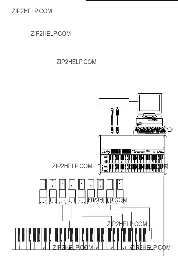
Drawbar 1 and Drawbar 2 each consist of a set of nine bars.
In Normal mode and Normal Edit mode, these bars have the following functions.
The white drawbars (8', 4', 2', 1') produce fundamentals. The black drawbars
Pulling out the four right bars to a greater extent will produce a
For example when you play middle C, each bar corre- sponds to the pitches shown in the diagram below. The further a bar is pulled out, the greater its volume will be.
For details on the function of the Drawbar 2 bars (EX Drawbar, EX Percussion) in EX mode and EX Edit mode, refer to the Drawbar 2 illustration (p.13), to the EX Edit mode Group 2 ???Ex Drawbar Type??? parameter, and to the Global mode Group 8 ???Type 1 Ex Drawbar 1??? through ???Type 4 Ex Drawbar 4??? parameters.
The
About MIDI
MIDI stands for Musical Instrument Digital Interface, and is a
Connecting an external MIDI sequencer or computer
If you want to play the keyboard of the
Sequencer/Computer
MIDI interface
MIDI IN 
 MIDI OUT

Appendices
Local Control On setting
If you make connections as shown on the preceding page, you must turn on the Echo Back setting of the external MIDI sequencer or computer (so that the data it receives at MIDI IN will be retransmitted without change from MIDI OUT), and turn off the Local Control setting of the
When you play the keyboard of the
In other words by turning the
To turn off Local Control, set the Global mode Group 4 ???MIDI Local Cntrl??? parameter to Off.
If you are using the
Connecting a MIDI keyboard
If you want to connect a MIDI keyboard to the
Set the Global mode Group 2 ???MIDI Upper Rx ch??? and ???MIDI Lower Rx ch??? parameters to match the MIDI channel of your connected MIDI device.
If you want to transmit program changes from the connected MIDI device or to control the panel keys of the
If you are recording your
Since Drawbar 1, 2, and DRAWBAR SELECT are not reproduced by program changes, use DRAWBAR SE- LECT to select the drawbars that you will use first in your performance. Then execute Global mode Group 7 ???Draw- bar Scan??? to transmit the state of Drawbar 1 and 2. Immediately when you begin recording, transmit a program change by selecting the program that you will use for your performance. Now the sequence will contain the data needed to reproduce the settings for each live set of drawbars.
When using a
With the factory settings, the
If you are using a
Set the Global mode Group 2 ???MIDI Upper 2nd ch??? and ???MIDI Lower 2nd ch??? parameters to other than Off. This will cause note messages with velocity to be transmitted on the specified MIDI channel.
However in this state, two sets of note messages (one
with variable velocity, and another with fixed velocity) will be transmitted, so you should also set the Global mode Group 2 ???MIDI Upper Tx ch??? and ???MIDI Lower Tx ch??? parameters to Off, so that the
Alternatively, you could set ???MIDI Upper 2nd ch??? and ???MIDI Upper Tx ch,??? and ???MIDI Lower 2nd Tx Ch??? and ???MIDI Lower Tx Ch,??? to different channels so that they do not conflict, and then make settings on the connected MIDI sound module so that it receives the note messages with variable velocity.
 If Global mode Group 1 ???Key Trigger??? is set to Shallow, the note message with fixed velocity will be transmitted when you have only pressed the key lightly. However, the note message with variable velocity will not be transmitted until you have pressed the key all the way. This means that if you have made settings to transmit note messages with variable velocity, it is possible for the
MIDI data dump
Exclusive data (internal settings) can be transmitted from the
Transmission
 While data is being transmitted, do not touch the keys, drawbars, or knobs of the
The following four types of data dump can be transmit- ted.
???Dump one program
???Dump all programs
???Dump global data
???Dump all data (programs and global data)
To transmit a data dump
1.Connect the MIDI OUT connector of the
2.Enter Global mode.
The key LED will light.
3.Press the PROGRAM [7] key, and then press the [??] key twice.
The display will indicate Dump.
4.Press the [WRITE/ENTER] key.
The display will indicate Dump Program, and ???Program??? will blink.
5.Select the data that you want to dump.
If you want to dump one program, press the [??] key once, and then use the
The programs that will be dumped will be the pro- grams contained in the mode that was selected before
37
Appendices
you entered Global mode in step 2. If you want to dump Normal mode programs, enter Normal mode before you enter Global mode in step 2. If you want to dump EX mode programs, enter EX mode before you enter Global mode in step 2.
If you want to dump all programs, press the [+] key once. The display will indicate Dump All Programs, and ???All Programs??? will blink.
If you want to dump global data, press the [+] key twice. The display will indicate Dump Global, and ???Global??? will blink.
If you want to dump all data, press the [+] key three times. The display will indicate Dump All Data, and ???All Data??? will blink.
6.Press the [WRITE/ENTER] key.
You will be asked to confirm the dump. If you decide to cancel, press the [EXIT] key.
7.Press the [WRITE/ENTER] key.
While the data is being transmitted, the display will indicate TxSysEx Processing...
The following table shows the data sizes and the time required for transmission.
 If you are saving dump data on a MIDI data filer, do not save multiple data dumps together. If you save multiple dumps together, the
2.Set the Global channel of the MIDI device to match the global MIDI channel of the
The global MIDI channel of the
When data transmitted to the MIDI device is to be sent back to the
For details on how to set the MIDI channel of your MIDI device, refer to the owner's manual for your device.
3.Set the Global mode Group 3 ???MIDI Rx Sys Exc??? parameter to Ena.
4.Send the data from the transmitting device.
For the procedure, refer to the owner's manual for your device.
 If the ???MIDI Rx Sys Exc??? parameter is set to Ena, data dumps can be also received in Normal mode or EX mode.
5.When transmission has been completed, the display will indicate RxSysEx Completed.
If the display indicates RxSysError, turn off the power, then hold down Program [2] and [7] keys and turn the power on. However, the contents of memory will be initialized at this time.
When receiving one program, the program data will be placed in the same mode as in which it was trans- mitted. At this time, the
Reception
 While data is being received, do not touch the keys, drawbars, or knobs of the
 While dump data is being received, the
MIDI cannot be transmitted or received while data is being written into memory. If you want the
All Program + Global Data Approximately 7 seconds
To receive a data dump
1.Connect the MIDI IN connector of the
MIDI messages that the
[...] indicates hexadecimal notation
MIDI channels
MIDI messages can be received if the MIDI channels of the transmitting and receiving devices match. There are sixteen MIDI channels;
MIDI messages are transmitted and received on the global MIDI channel. The global MIDI channel is the basic channel for MIDI transmission and reception, and is set by the Global mode Group 2 ???MIDI Global Ch??? param- eter.
(n: channel, kk: note number, vv: velocity)
Each time you press or release a note on its keyboard, the
Very few devices transmit
38

Appendices
Program change / Bank select
Changing the program / bank
Program change [Cn, pp]
(n: channel, pp: program number that selects from up to 128 sounds)
???Programs
Pitch bend
Pitch bend change [En, bb, mm]
(n: channel, bb: lower byte of value, mm: upper byte of value, together indicating a value of 16384 steps where 8192 [bb, mm=00H, 40H] is the center value)
The
Control change
[Bn, cc, vv]
(n: channel, cc: control change number, vv: value)
???Control changes can be turned on/off by the Global mode Group 4 ???MIDI Rx C. Change??? parameter.
To silence all notes
All Note Off (CC#123) [Bn, 7B, 00] (value is 00)
When this message is received, all
All Sound Off (CC#120) [Bn, 78, 00] (value is 00)
When this message is received, all sound currently being produced will be silenced. While the All Note Off mes- sage allows the decay of the notes to remain, All Sound Off causes the sound to be silenced immediately.
However, these messages are intended for use in emer- gency situations, and are not used during a performance.
To reset all controllers
Reset All Controllers (CC#121) [Bn, 79, 00] (value is 00)
When this message is received, the values of all currently- operating controllers will be reset.
About system exclusive messages
Since system exclusive messages can be used by each manufacturer as they wish, these messages are used mainly to transmit or receive sound data or editing data for parameters that are specific to a particular device. The system exclusive message format for the
F0: Exclusive status
42: Korg ID
3n:
5B:
ff: Function ID (type of message)
???
F7: End of exclusive
Each
 To obtain copy of the ???MIDI Implementation??? which includes MIDI exclusive format information, please contact your Korg distributor.
Universal system exclusive
Some system exclusive messages have officially defined uses; these are called universal system exclusive mes- sages.
Of the universal system exclusive messages, the
Inquiry Message Request [F0, 7E, nn, 06, 01, F7] Inquiry Message [F0, 7E, nn, 06, 02, (nine bytes), F7]
When an Inquiry Message Request is received, the
Transmitting sound settings and other data (Data Dump)
Program and global settings can be transmitted as MIDI exclusive messages. The action of transmitting MIDI exclusive messages to an external device is called Data Dump.
By performing a data dump, you can save sound settings or other types of data on an external device, or change the sounds or settings on another
The
???Dump All Program, Dump Global, or Dump All Prog+Global transmits or receives internal memory data.
When the
???Dump Program transmits or receives data for the program in the edit buffer.
When the
???In Global mode, a data dump can be performed when the Dump Program, Dump All Program, Dump Global, or Dump All Prog+Global commands are displayed. A data dump will also be transmitted when a dump request is received if the ???MIDI Rx Sys Exc??? parameter is set to Ena.
Data that is received by Dump Program can be written into internal memory by a Write Request.
If notes ???hang??? (fail to stop)
If a note refuses to stop sounding, press the [EXIT] key.
39
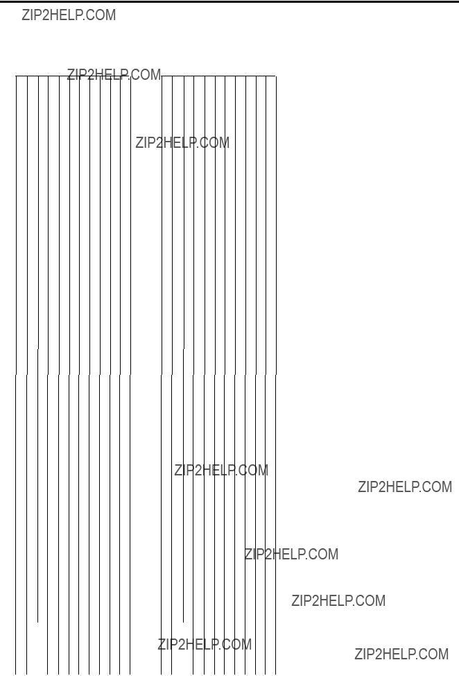
Appendices
3. Voice name list
Mod Wheel assign = ???Click Level???
Normal mode programs
Mod Wheel assign = ???Ex Lm Level???
EX mode programs
Pedal1/2: ???Assignable Pedal/SW 1??? / ???Assignable Pedal/SW 2??? settings. RF: Rotary Fast control WB: Wheel Brake control
Demo song names
* Special thanks for preset voicing and demo songs
1 Y???s Groovin???
DS: Derek Sherinian
DM: Don Muro
LS: Lonnie Smith
TC: Tom Coster
BC: Bill Champlin
AK: Al Kooper
GP: Greg Phillinganes
BA: Brian Auger
2 Katana 3 Church Hymn 4 TC Kool Blues 5 GP Jazz Waltz 6 BC CX Preclude 7 GP Gospel 8 Samba de Rit 9 Mama takes me
and more
All songs copyright by KORG Inc.
40
Appendices
4. Troubleshooting
???Is the power switch turned ON?
Check the on/off setting of the power switch.
No sound
??? Are the connected devices or headphones connected correctly?
???Are your amp and/or mixer turned on?
???Is the [MASTER LEVEL] knob turned up?
???Is the Global mode Group 3 ???Local Control??? parameter turned On?
Check the parameter settings.
???Are the Drawbar 1 and 2 bars pulled out?
Pull out the bars.
Sound does not change when you move Drawbar 1 or
2bars
???Is the DRAWBAR SELECT section set correctly?
If you want to play using the bars, select the [DRAW- BAR 1] key or [DRAWBAR 2] key in the DRAWBAR SELECT section. ............................................(see p.12, 13)
Percussion does not sound
???Are the settings of the DRAWBAR SELECT section correct?
If you want to use the PERCUSSION section keys, select the [DRAWBAR 2] key in the upper DRAWBAR SELECT section. .................................................. (see p.17)
??? Is the Normal Edit mode ???DB Preset's Perc??? parameter
???Are the
The Normal Edit mode ???Percussion Nrml Level??? parameter value plus the ???Percussion Soft Off??? parameter value will be the level of the soft percus-
sion. If this is zero or less, the percussion will not be heard when Soft is selected. .............................. (see p.25)
Rotary speaker effect cannot be obtained
???Is the amp selection correct?
For the Normal Edit mode or EX Edit mode Group 4
The
???If you want to receive MIDI exclusive messages, is the ???MIDI Rx Sys Exc??? parameter set to Enable (Ena)?
Check the parameter setting.
???Does the
Pedal switch or expression pedal connected to the rear panel does not operate as you intend
???Is Pedal 1 or Pedal 2 selected for the Global mode Group 1 ???Prog Up Ctrl??? or ???Prog Down Ctrl??? param- eter?
It is possible to assign more than one function to a pedal switch or expression pedal. However if a pedal switch etc. is selected by the Global mode Group 1 ???Prog Up Ctrl??? or ???Prog Down Ctrl??? parameter, the Global mode setting will take priority, and the Normal Edit mode and EX Edit mode settings will not be used. Please check the settings of these parameters.
An external MIDI device acts in unexpected ways when connected to the
???Is there a CC# conflict?
Most operations of the
Check the control change related parameters in Global mode Group 4 and 5, and turn unneeded parameters off or change their control change number.
41
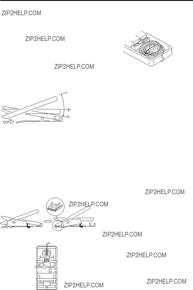
Appendices
5.Operation of included Expression pedal
Fortissimo function
This allows you to selectively emphasise parts of your performance.
As shown in the diagram, the pedal angle is 30?? when fully raised. The pedal will rest at any point you take your foot off from fully raised to standard position.
If you depress the pedal further from standard position, it will return to standard position when you take your foot off.
Also, by adjusting the screw on the bottom, you may adjust the spring return range from
Cable storage
Store the cable as shown.
20????? Range of free ??? movement
30?????
Standard position
Spring return range
Selectable pedal angle
As shown below, you may change the pedal angle to fit your plying position.
To select pedal angle
1.Loosen hook screw with a screwdriver.
2.Move the pedal body to the position in the illustra- tion.
3.Retighten the hook screw.
 hook screw
hook screw
42

Appendices
6. Specifications and options
Tone generator section
Tone generator: Tone wheel organ modeling tone generator
Polyphony: Full keyboard polyphony
Modes
Normal mode, EX mode, Normal Edit mode, EX Edit mode, Global mode
Effect section
Vibrato/chorus, rotary speaker, overdrive, reverb
Number of programs
Normal mode: 64
EX mode: 64
Keyboard
61 note x 2
Controllers
DRAWBAR SELECT section (for UPPER Keyboard):
[DRAWBAR 1] key, [DRAWBAR 2] key, [PRESET DRAWBAR] key
DRAWBAR SELECT section (for LOWER Key- board): [DRAWBAR 1] key, [DRAWBAR 2] key, [PRESET DRAWBAR] key (these are for the Lower tone generator)
DRAWBAR section: Drawbar 1, Drawbar 2
PERCUSSION section: [ON] key, [SOFT] key, [FAST] key, [3rd] key
ROTARY section: [ON] key, [STOP] key, [FAST] key
VIBRATO CHORUS section: [UPPER] key, [LOWER] key, [VIBRATO/CHORUS] knob
AMP section: [MASTER LEVEL] knob, [TREBLE] knob, [BASS] knob, [REVERB OFFSET] knob
Other: [EXPRESSION/OVERDRIVE] knob, [DIS- PLAY] key, [EX MODE] key, [EDIT] key, [GLOBAL] key, [WRITE/ENTER] key, [EXIT] key, PROGRAM
Outputs
OUTPUT L, R jacks:
Maximum output level ..... +17.5 [dBu]
Load impedance ..... 10
PHONES jack:
Maximum output level ..... 50 mw @ 32 ohms / channel
Control inputs
EXPRESSION PEDAL jack
ASSIGNABLE PEDAL/SW 1, 2 jacks
Other
MIDI IN connector, MIDI OUT connector, MIDI THRU controller, AC power supply connector, Power switch
Power supply
AC Local voltage
Dimensions (W x D x H)
1,102 x 620 x 944 mm / 43.39 x 24.41 x 37.17 inches
1,102 x 620 x 221 mm / 43.39 x 24.41 x 8.70 inches (including rubber feet)
Weight
50 kg / 110.23 lbs.
Power consumption
14 W
Included items
Power cable, Expression pedal, Stand
Options
*Appearance and specifications of this product may change without
notice. (As of March, 2002.)
43
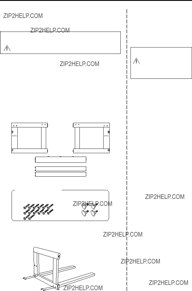
Appendices
7. Assembling the stand
How to assemble the stand
 Caution
Two or more persons are required in order to assemble the stand.
Cautions for assembly
Please observe the following points to ensure that the stand is assembled correctly.
???Perform the assembly steps in the specified order, making sure that you use the correct parts and that they are in the correct orientation.
???If you jar the organ before fastening it to the stand, it may fall over. Please be careful.
Assembly procedure
You will need to provide a Philips screwdriver.
1.Open the carton and take out the parts.
Make sure that you have the following parts.
?????????????????? ??????????????? ???
????????????????????? ?????????????????????
???????????? ??????????????? ??? ??? ???
????????????????????? ????????????????????? ??? ???
????????????????????? ????????? ??? ????????? ?????? ???????????????????????????
2.Lightly attach the rear braces to the side panel (L).
Insert the two protrusions on the left ends of the rear braces into the holes of the side panel (L), and lightly fasten them in place using four bolts. Do not tighten these bolts yet.
7.Assemblage du pupitre
M??thode d???assemblage du pupitre
 ATTENTION :
Deux ou davantage de personnes sont n??cessaires pour proc??der ?? l???assemblage du pupitre.
Pr??cautions ?? prendre pour le montage
Respecter les points suivants pour s???assurer que le pupitre est mont?? correctement.
???Proc??der ?? l???assemblage en respectant les ??tapes dans l???ordre sp??cifi??, en s???assurant d???utiliser les ??l??ments ad??quats et dans le sens correct.
???Si l???orgue est heurt?? avant d?????tre fix?? au pupitre, il risque de tomber. Faire tr??s attention ?? ce point.
M??thode d???assemblage
S?????quiper au pr??alable d???un tournevis Philips.
1.Ouvrir le carton d???emballage et en sortir tous les ??l??ments.
V??rifier si les ??l??ments suivants sont pr??sents
2.Fixer l??g??rement les supports arri??re au panneau lat??ral (G)
Ins??rer les deux saillies des extr??mit??s gauches des supports arri??re dans les orifices du panneau lat??ral (G), puis les fixer l??g??rement ?? l???aide de quatre vis. Ne pas serrer les vis ?? ce stade.
44
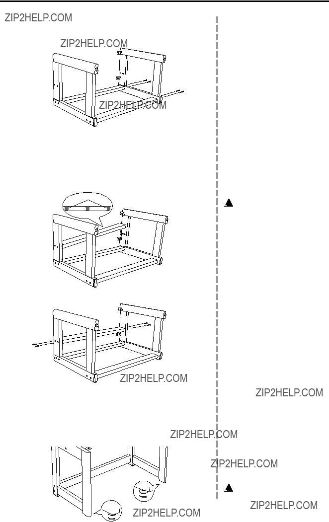
Appendices
3.Lightly attach the rear braces to the side panel (R).
Insert the two protrusions on the other ends of the rear braces into the holes of the side panel (R), and lightly fasten them in place using four bolts. Do not tighten these bolts yet.
Fasten the bolts only lightly /
Fixer l???g???rement les vis
4. Attach the center brace.
Position the felted side of the center brace away from yourself. Insert the protrusions on one end of the center brace into the holes of one side panel, and then insert the protrusions on the other end into the holes of the other side panel.
 If you attempt to force the center brace into place, the side panels or back braces may break. If you have difficulty, loosen the bolts that you fastened in steps 2 and 3.
Felt / Feutre
5. Use bolts to fasten the center brace.
6.Firmly tighten all bolts that have not yet been tightened.
7.Make sure that there are no gaps between the parts of the stand, that the stand is not crooked, and that all bolts are securely tightened.
8.If the stand wobbles, rotate the two adjusters so that the stand firmly contacts the floor.
 Be careful not to pinch your hand while making adjustments.
3.Fixer l??g??rement les supports arri??re au panneau lat??ral (D)
Ins??rer les deux saillies des extr??mit??s gauches des supports arri??re dans les orifices du panneau lat??ral (D), puis les fixer l??g??rement ?? l???aide de quatre vis. Ne pas serrer les vis ?? ce stade.
4.Mettre le support central en place.
Tourner le c??t?? feutr?? du support central vers l???ext??rieur. Ins??rer les saillies d???une extr??mit?? du support central dans les orifices d???un panneau lat??ral puis ins??rer les saillies de l???autre extr??mit?? dans les orifices de l???autre panneau lat??ral.
 Ne pas forcer pour mettre le support central en place sinon les panneaux lat??raux ou les sup- ports arri??re risquent de casser. En cas de difficult??, desserrer les vis fix??es aux ??tapes 2 et 3.
5.Fixer le support central ?? l???aide de vis
6.Serrer convenablement toutes les vis qui sont encore l??ches.
7.V??rifier qu???il ne reste pas d???espace entre les diff??rents ??l??ments du pupitre et si le pupitre n???est pas de travers. V??rifier ??galement si toutes les vis sont bien serr??es.
8.Si le pupitre est bancal, tourner les deux vis de r??glage de sorte qu???il repose correctement sur le sol.
 Faire attention de ne pas se pincer les mains lors des r??glages.
45

Appendices
9.Attach the organ to the stand.
Place the organ on the stand, and use the four wing knobs to fasten it from below.
 When placing the organ on the stand, be careful not to pinch your hand. Lower the organ slowly onto the stand, and do not drop it.
9.Fixer l???orgue au pupitre
Placer l???orgue sur le pupitre et l???attacher par en dessous ?? l???aide des quatre boulons ?? ailettes.
 Lors de la mise en place de l???orgue sur le pupitre, faire attention de ne pas se coincer la main. Abaisser l???orgue lentement sur le pupitre, sans le l??cher.
Wing knobs / Boulons ??? ailettes
Check after assembly
??? Make sure that none of the bolts are loose.
Other cautions
After assembly, please observe the following cautions.
???Loosened bolts
As time passes after assembly, bolts may come loose. We recommend that you regularly check for loose bolts. If you feel that the stand sways, it is possible that the bolts are loose. Please
???Transport
Remove the organ from the stand, and transport the organ and stand separately. After transport, reattach the organ as described in these instructions.
???Disassembly
If it is necessary to disassemble the stand, do so in the reverse order of assembly. After disassembly, save the bolts and other parts so that they are not lost.
V??rification apr??s montage
???V??rifier si aucune des vis ou des boulons ne sont l??ches.
Autres pr??cautions ?? prendre
Apr??s le montage, prendre les pr??cautions suivantes :
???Vis et boulons desserr??s
Au fil du temps, apr??s le montage, les vis et boulons risquent de se desserrer. Nous vous recommandons d??s lors de les inspecter r??guli??rement pour voir s???ils sont bien serr??s. Si le pupitre semble vaciller, il est possible que les vis et boulons soient trop l??ches. Dans ce cas, il convient de les resserrer.
???Transport
Retirer l???orgue du pupitre pour transporter les deux ??l??ments s??par??ment. Apr??s le transport, fixer de nouveau l???orgue au pupitre comme expliqu?? dans ces instruc- tions.
???D??montage
Si le d??montage du pupitre s???av??re n??cessaire, proc??der dans l???ordre inverse au montage. Apr??s le d??montage, conserver soigne
46

Consult your local Korg distributor for more information on MIDI IMPLEMENTATION.
47