i1800 Series Scanners
Key Operator Guide
i1800 Series Scanners
Key Operator Guide

Key Operator Training
Welcome to the enhanced Kodak i1800 Series Scanner Key Operator Training. This course is designed to provide you with a thorough understanding of the operation and care of your new
Checklist
Following is a summary of the topics that will be covered. This class will require between 1.5 and 2 hours of dedicated class time to complete.
Introduction
 Review of Resources
 Scanner orientation
Document journey through the transport
Replacement of consumables
Maintenance
 Calibration
What type of scanning does your site do?
Basic printing
 Overview of accessories
OCP and touchscreen overview
Scan Validation Tool
Troubleshooting
Service issues
Safety
Other issues
.

INTRODUCTION
This training program provides you with the
The operation of your site???s particular scanning application and procedures will not be covered as part of this training. The Kodak i1800 Series Scanner is supported by a number of different scanning applications that have been developed by many companies around the world. We recommend that you request software and image processing training from the original software vendor who knows these products best. If your site has chosen Kodak Capture Software as your scanning application, then we would be glad to arrange a separate training session that is customized to meet your particular needs.
REVIEW OF RESOURCES
As you gain experience with the scanner you may have questions about different features and capabilities that did not occur to you during the class today. In order to help you find answers you need in the future, we have compiled this list of resources and what you will find in each.
??User???s Guide
Publication
This is the place to go for ???how to??? type questions related to the operation of the scanner. Much of what will be covered here is detailed in the User???s Guide; from how often to change the
??Quick Tips Guide
Publication
This is a handy reference card for quickly finding catalog numbers for consumables or a reminder of proper cleaning procedures at the end of your shift.

??Image Processing Guide
Publication
This is the complete reference for the many different ways this scanner can capture images. ???What are all those options for image quality on the TWAIN or ISIS driver for???? Or ???How do I setup my level to follow level rules for 3 level indexing???? Those answers and more are in the Image Processing Guide. As an operator, this level of information should not be needed, but if you are involved in job setup you will be glad to have all of the capabilities of the scanner spelled out for you in this guide.
??Installation Planning Guide
Publication
This guide should have been provided to your site well before the installation date and should have been used as a guide for planning for the installation day. This document gives details on the site specification requirements (such as power quality) and layout expectations for both you and Kodak during the scanner???s installation.
??Brightness & Contrast Control Reference Guide
Publication
This guide should be referenced when using the Brightness and Contrast Controls utility if you ever need to create custom ???color tables??? that allow you to control the colors that are used to create your images. Again, like the Image Processing Guide, as an operator only, this level of information should not be needed unless you are involved with job setup.
??Supplies and Consumables Catalog
Publication
This is where you will want to go to determine the size of a consumables kit you want to order: Large, Extra Large, or Extra Extra Large. All consumables for all Kodak Document Scanners are listed here.
??
Our scanner driver (TWAIN) now includes a complete
??www.Kodak.com
The latest scanner information and drivers can always be found on our website. To make it easier for you to get to the pages related to our document scanners, use these URLs:
Kodak frequently adds features to our scanners though driver updates so your scanner application support can go to our website for the most
Create a folder on the scanner???s host PC desktop called ???Kodak Scanner Manuals??? and copy these files from the Kodak i1800 Series Scanner Firmware, Drivers and Users Guide CD into that folder so they will be at the operator???s fingertips if needed.
Also within that folder create a shortcut to the web page
www.Kodak.com/go/disupport.
Be sure the hard copy of the Users Guide and Quick Tips Guide is properly stored in the pocket inside the door of the scanner???s base.

SCANNER ORIENTATION
You will now have a demonstration of the scanner using the Count Only mode and the instructor will point out the basic components of the Kodak i1800 Series Scanner.
There are two power switches, but the main power switch on the back of the scanner will rarely be used.
Main power switch
Front view
Have each student adjust the scanner to their personal height and scan a stack of documents in Count Only mode.

DOCUMENT JOURNEY THROUGH THE TRANSPORT
Now that you have experienced the scanner from the operator???s point of view we will walk you through the scanner from the document???s point of view. We will follow the path of a document from its start in the input elevator, to separation from the stack, to ultrasonic
??Note the green caution labels
??Stage one: Input elevator
-Independently adjustable side guides for offset scanning
-Paper present sensor
-Lock/Unlock switch
-Long document wire bail
-The host scanning application can be used to set the elevator to four different starting heights.
??Stage two: Document separation from the stack
-Opening the pod
-Location and functions of the:
??
??separation roller
??feed module
-Demonstrate that there is a Gap Release button that lowers the separation roller to allow feeding of very thick or damaged documents.
??Stage three:
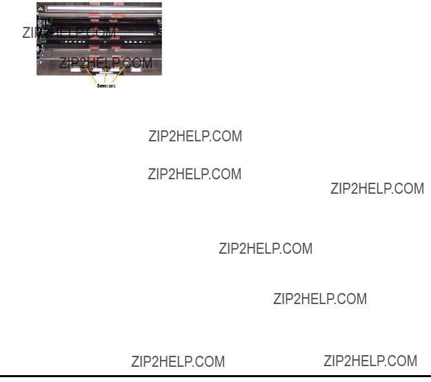
-Review transport rollers, UDDS sensors and patch head sensors.
-Review printer baffle; remove front printer background strips and show front ink blotters.
??Stage four: Imaging
-Image Background. Remove and talk about scratches. Talk about white background accessory and use.
-Imaging Guides (upper and lower). Talk about the white patch, removal of the imaging guides, and how to clean imaging guides using Staticide wipes. Point out that the upper imaging guide has ribs to prevent ink from smearing and the lower imaging guide does not.
-Lamps. Not customer replaceable.
NOTE: The bottom lamps have a cover glass between them but the upper lamps do not. Do not insert anything into the upper camera area.

??Stage five:
-Rear ink blotters; show the location and how to replace them.
??Stage six: Output
-Review the output tray: side guides and end stop. Review the various positions that the output tray can be placed in using the wire legs on the bottom of the tray. Also mention the long document wire bail and the short document stacker.
Answer any questions regarding the components of the transport.
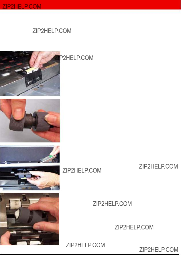
REPLACEMENT OF CONSUMABLES
In this section the instructor will identify all the consumables (parts of the scanner that will wear out during normal use) and instruct you on the proper procedures for the replacement of these items. Just as changing the oil and replacing worn tires on your car is necessary to keep it running properly, the timely replacement of the scanner???s consumables is critical to its performance. As an operator, you will experience fewer paper feeding problems if the consumables are replaced when they are worn.
Open the User???s Guide to the Replacement Procedures in the Maintenance chapter.
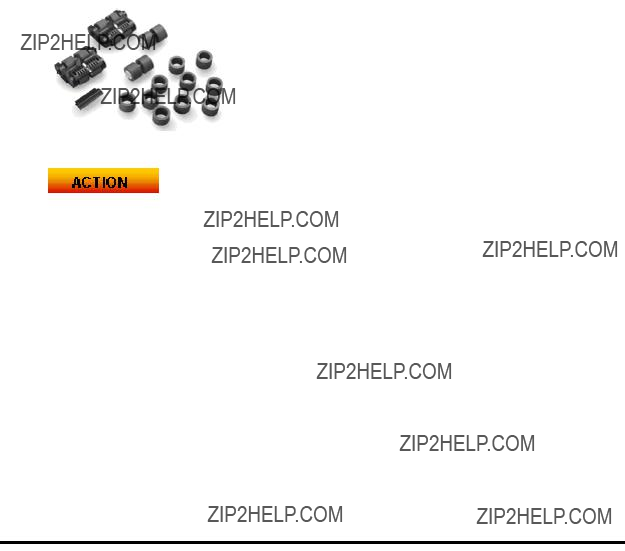
Feed module tires and separation roller tires: tire life will vary depending upon paper types, environment and cleanliness. Nominal tire life for clean,
Feed Module: replace after every 4th replacement of tires, approximately after 2,400,000 scans. Install a new feed module and separation roller at the same time.
Separation roller: replace after every 4th replacement of tires, approximately after 2,400,000 scans. Install a new feed module and separation roller at the same time.

Tip: Suggest that the customer have a feed module and separation roller with new tires installed ready to go. The customer could then change the feed module and separation rollers quickly and avoid
Imaging guides: replace only when the imaging guides are heavily scratched and defects show in the scanned images. Image defects that are normally caused by scratched image guides are lines or streaks in the image in the direction that the paper is moving through the transport.
Backgrounds: replace only when the backgrounds are scratched and defects show in the scanned images. Image defects that are normally caused by scratched black backgrounds are black borders on the left or right side of an image (assuming the image is not rotated).
??Show the students the Replacement Procedures in the Maintenance chapter in the User???s Guide.
??Each student should individually remove and replace each these items including replacing tires on the feed module and separation roller.
??Copy the Consumable Replacement Log sheet at the end of this Training Guide and instruct the students to keep this in the storage compartment on the inside door of the scanner and update it whenever replacing a consumable.
MAINTENANCE
All paper scanners that transport documents create paper dust and collect ink residue on the components of the transport that come into contact with the paper. This section of the class will detail the proper cleaning procedures for your scanner. The most frequent image quality problems with document feeding scanners are lines or streaks in the scanned image and black image borders (which are almost always caused by dust on the imaging components of the scanner). A Kodak recommended cleaning frequency schedule will be covered that, if followed, should prevent any unnecessary interruptions in scanning or service calls due to problems related to improper maintenance. The instructor will also review the equipment you should purchase (vacuum) and supplies that should be used when cleaning the scanner. We will also cover some things that should not be done when cleaning the scanner as they may damage the scanner.
??Open the User???s Guide to Chapter 5, Maintenance and the review the complete scanner cleaning procedure noting the following:
-Vacuuming the transport is essential to removing dust.
-Streaks or lines in the scanned image that are in the direction of the documents travel are likely caused by dust or debris on the imaging guides or in the image path (lower cover glass between the lamps). Also note that the back side of the imaging guides must be cleaned as well as the front side.
-The front side of the imaging guide is in the top or pod side of the transport and the rear side of the imaging guide is in the bottom or base side of the transport. If a streak is visible on the front side scanned image, then clean the imaging guide in the pod.
-For the scanning of the back of documents there is a cover glass that is beneath the lower imaging guide that may collect dust during scanning. When cleaning the scanner, be sure to remove the lower imaging guide and clean this cover glass.
??Review the Quick Tips Guide noting the frequency chart for maintenance procedures.

??Review the proper materials used in cleaning
-Vacuum: a good quality vacuum with
CALIBRATION
This topic will review the Image and UDDS calibration needs of the i1800 Series Scanner.
??Image Calibration
The scanner was designed to operate for hundreds of hours before image
-Only calibrate the scanner when the scanner indicates that it needs to be calibrated with a ???Calibrate Now??? message.
-Never calibrate a dirty scanner.
-If an image ???Calibrate Now??? message is displayed, Image calibration should only be performed using the 12 x
??UDDS Calibration
UDDS calibration is designed to adjust the Ultrasonic Double Document Detection sensors of the scanner. During normal scanner operation, this calibration should not be required. Only perform the UDDS calibration if a message is posted that indicates that a UDDS Calibration is required.
-If a UDDS calibration message is displayed, UDDS calibration should only be performed using a US letter or A4 size sheet of 20 lb. or 75 g/m2 bond paper fed in the center portrait feeder orientation.

WHAT TYPE OF SCANNING DOES YOUR SITE DO?
You should now have a solid understanding of the basic operation of the scanner. The following topics (Printing / Touchsceen / Accessories) deal with operations that will vary depending on the type of scanning that is being performed. If the instructor does not yet have an understanding of the different types of scanning that you expect to perform, the instructor will ask you about your scanning jobs so that he/she may customize the following topics:
??Does your site intend to use image addressing?
??Do you ever print on the documents during scanning? If yes:
-Would you need front
-Do your printing needs include being able to print high resolution characters across the page as opposed to down the page in the direction the document goes through the transport?
??Does your site use patch separator sheets?
??Do you scan documents longer than 17 inches?
??Do you scan very thin documents?
??Do you have jobs with documents that you need to
The instructor should understand and review the basic site scanning needs, and adjust the remaining sections as needed.
BASIC PRINTING
If your site is will be using the Enhanced Printer the replacement and maintenance will be an important part of operating the scanner.
Skip this section if your site does not currently print and does not plan to print on your documents in the future.
Open the User???s Guide to Chapter 4, The Enhanced Printer and Patch Readers and review the complete printing procedure noting the following:
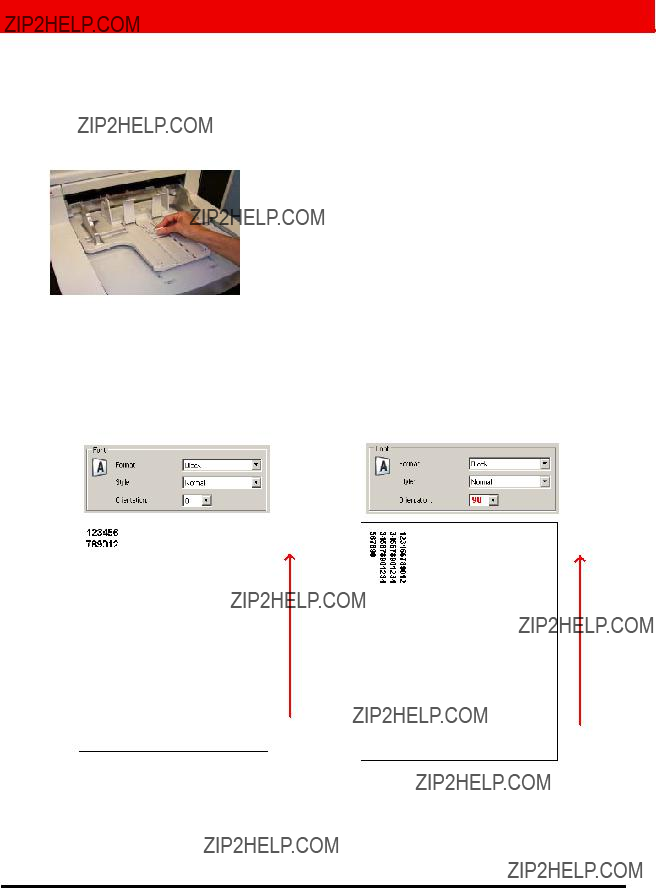
??The Enhanced Printer will allow printing of up to 40 characters down the page in the direction of the paper transport.
??Explain the use of front and rear printing
-Front
-Rear
??Demonstrate the locations and access to the front and rear printing areas.
?? Show replacement of the ink cartridge using the front side printer.
??Show location of horizontal print positions for front and rear printing. Also note that the location of the side guides and the justification of the documents in the input tray will determine the location of the printing on the page.
??Demonstrate how to change from front to rear printing. - Move the carrier first and then reboot the scanner
??Show replacement of the front and rear ink blotters.
??Your host application may enable the Omit Print option when scanning, that when touched, will prevent printing on the next document. Printing is only disabled for one document when this option is selected.

??There is a Print Test function available on the touch screen of the scanner. This test will print a ???ladder??? target where each vertical line is printed by one of the jets in the print head. If a line is missing, one of the jets is not working. Dabbing the print head with a Staticide wipe will often open clogged jets. Remember to use plain white paper when running the print test.
Each student should remove and replace an ink cartridge.
NOTE: Running a Print Test will be covered later in this class.
OVERVIEW OF ACCESSORIES
This section covers the accessories that are available for the i1800 Series Scanner. The scanning needs of your site may require the use of all or none of these accessories, depending on the type of documents that you will be scanning and your printing requirements.
??Short Document Output Tray
This accessory was shipped with your scanner and should be used if you are scanning stacks of checks or other
??High Resolution Printer
-This is a purchased accessory that will provide 600 dpi front side
-Changing to rear printing is not possible after the High Resolution Printer is installed.
-Block mode printing format is available only with the High Resolution Printer. This format will allow for up to 6 characters to be printed across the paper.
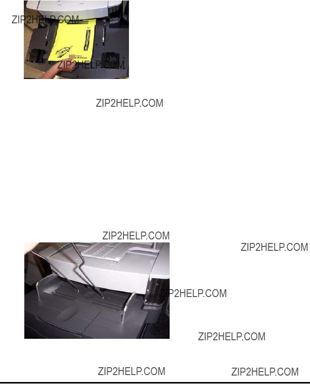
??Manual Feed Shelf
This is a purchased accessory that can be installed and removed by the customer. The Manual Feed Shelf is used when the scanned documents must be
??White Background Accessory
The White Background Accessory is a purchased replacement for the standard Black Background strips that come with the scanner. The Black Background strips that are magnetically attached are easily removed to allow for customer installation of the White Background strips. If the documents that you are scanning are very thin, the standard black backgrounds may show through the paper and create shadows in color or grayscale documents or ???noise???/specks in black and white documents. When changing between the black and white backgrounds, the scanner must be rebooted. When the white backgrounds are installed the scanner will not be able to perform image auto cropping and border removal. Black backgrounds are also required when performing image calibration.
??Long Document Extension Wires
If your site is scanning documents longer than 17 inches, ask your Field Engineer to provide up to two of these extension wires (one for the input tray and one for the output tray) at no charge. If more than two are required, they may be purchased though Kodak Parts Services.
These extensions attach to the input and/or output trays to help support longer documents as they are fed into the transport and exit the transport. Three sizes are available:
??
This consumable kit is for customers who are scanning very thin documents. This kit contains components designed to improve feeding of a paper weight range of 25 g/m2 to 75 g/m2 kg (7 to 20 lbs).
896 5279
Identify any accessories that the customer may find useful in improving productivity.
OCP AND TOUCHSCREEN OVERVIEW
In order to make the Kodak i1800 Series Scanner as easy to use as possible it was designed with a full color touchscreen. All of the operator functions of the scanner are available (in several languages) though the Operator Control Panel (OCP). This section describes the use and maintenance of the OCP. Both the Image Address - Enabled and Image Address - Disabled versions of the touchscreen will also be described. (The version that your site will not be using can be ignored.)
If the instruction has not already done so, they should put the scanner in the Image Address mode that the customer will be using. It is not expected that a scanner operator would need, or be expected to, change between Image Address - Enabled and Image Address - Disabled modes.
Only use your fingertip when touching the touchscreen. The touchscreen is not designed to be used with a stylus. Use of a stylus or other instrument could damage the touchscreen and is not covered under the scanner???s warranty or under the terms of any Service Agreement.
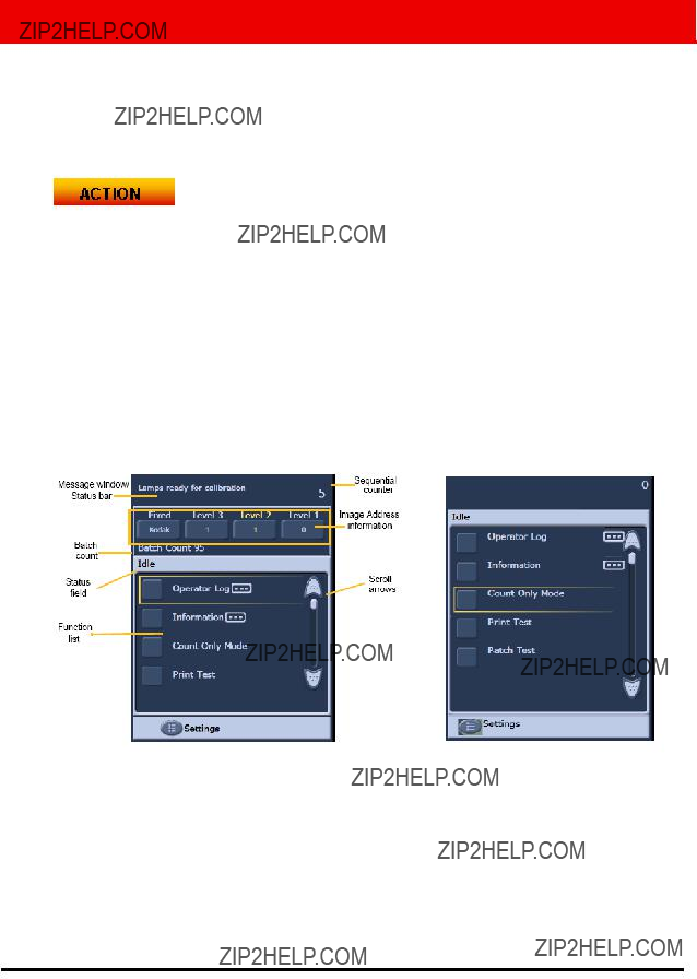
??IDLE
When the scanner is first powered up, it comes to the Idle screen. At this point there are several screens that can be entered to test the scanner and review scanner information and logs. Scanning cannot be started until the host computer has setup the scanning job.
-Review the different fields of the Idle screen.
-Viewing the Operator Log
??This log is reset whenever the scanner is powered off but the messages are still available through the internal scanner log visible though SVT (Scan Validation Tool)
??Log messages with a time stamp of 12:00:00 are normal when first powering on the scanner. These messages happened before the scanner was able to connect to the host computer and determine the local time.
-Information
??Last image Address / Total documents Scanned / Firmware version
-Count Only mode
??This function can be used if you just want to count the pages in a batch but not scan them. This can also be used to run the transport cleaner sheets during maintenance.
-Print Test
??Prints ladder test pattern (see BASIC PRINT section for more information)
-Patch Test
??This function can be used to test the quality of your patch sheets. If your patch sheets are not being read by the scanner, run this test to find any poor quality patch sheets.
??SETTINGS
-Volume: used to change the volume of the scanner speaker.
-Tones: used to change the alert tones used for functions, such as, multifeed alert. This is useful if more than one scanner is in the same area.
-Language: the language that is used for the buttons on the OCP can be changed with this function. The operator can easily select whichever language they are most comfortable with without rebooting the scanner.
Each student should navigate through the menus on the touchscreen and perform the following:
-View the Message Log screen.
-View the Scanner Information screen.
-Scan a stack of documents in Count Only mode.
-If using printing, put some plain white paper in the feeder and run a print test.
-If using patch sheets, put some patch sheets in the feeder and run a patch test.
-Set the Volume, Tones and Language to their personal preferences.
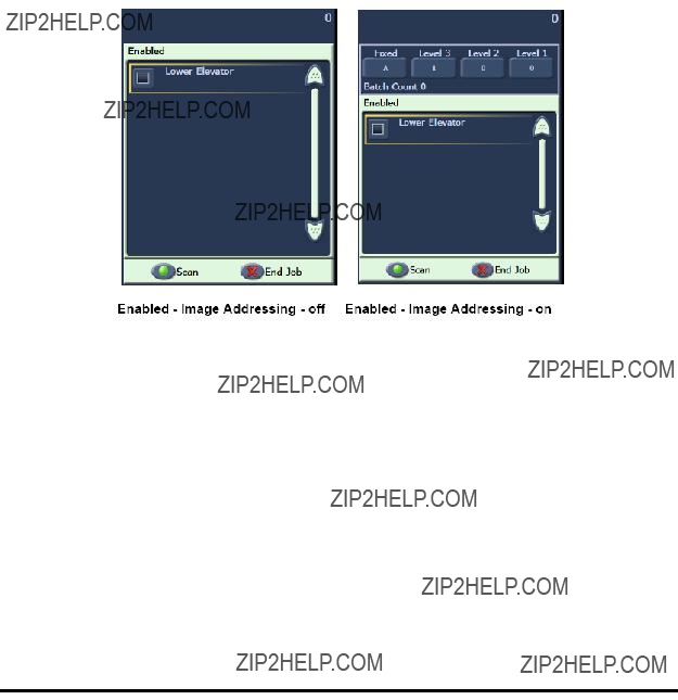
??ENABLED screen
Before you start scanning, the host scanning software must set up the scan job in the scanner. After the scanner is set up, the host software can either automatically start scanning or can have the scanner wait until scanning is started by the operator.
If
If there is no paper in the input tray and the scanner is enabled with
If the scanner is not set up to

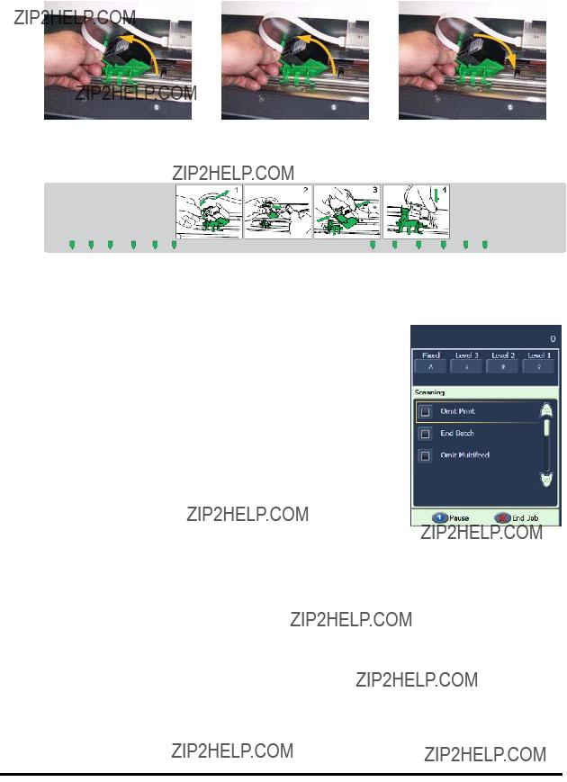
??SCANNING screen
When the scanner is feeding paper, the touchscreen shows the Scanning screen. There may be up to three function buttons available on this screen. The host computer scanning software determines the function buttons that are displayed. There is always a Pause button available that can be used to stop the documents from feeding into the scanner. If the Pause button is touched, you will be able to start scanning again with the Scan button. While you are scanning, the number of pages fed will be counted in the top right of this screen.
If you have Image Addressing enabled, the Image Address window will be displayed. The Image address of the next document to be scanned will be displayed in this window. If you need to manually increase the image address, you can touch one of the Level buttons. Finally, if your host computer scanning software has enabled the batching feature, the current Batch Count will be displayed in the lower left side of the Image Address screen.
The instructor should start a scanning job from SVT (Settings Shortcut - Color
Document) that does not have  or the
options enabled. The operator should scan documents and use the Pause button.
?? Power Saver window
If the Power Saver feature has been enabled by your host scanning application, the Power Saver Count Down window will be displayed if the scanner is left idle. The time before this message may be between 5 and 60 minutes. If the Close button is not touched before the timer reaches 0, the scanner will shut down. To wake up the scanner either add or remove paper from the input tray.
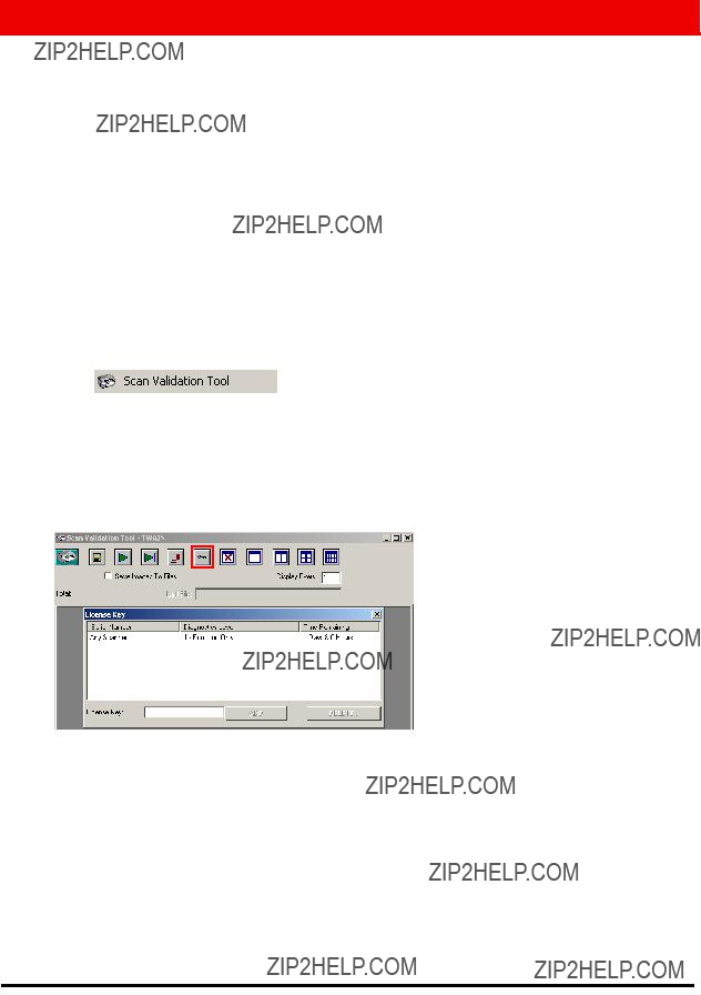
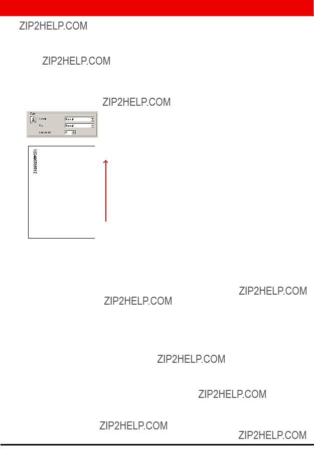
SCAN VALIDATION TOOL
Your company will have purchased one of the many production scanning applications that support the i1800 Series Scanner for your daily scanning needs. There is a scanning utility called the Scan Validation Tool that has been installed on your host computer. This utility can be used for tasks such as viewing the complete Scanner Operator Log or checking that the scanner is functioning correctly when trying to determine if there is a problem with the scanning software or hardware. This utility allows access to two different software drivers (TWAIN and ISIS). This class will not cover all the options available on the scanner. The TWAIN driver will be used to access the logs. For more information on the driver options, refer to the Image Processing Guide mentioned earlier in this class.
??Starting SVT
From the Start menu on the host computer select:
1.All Programs
2.Kodak
3.Document Imaging
4.
??License key - Key icon
During a support call, Kodak Support may provide an
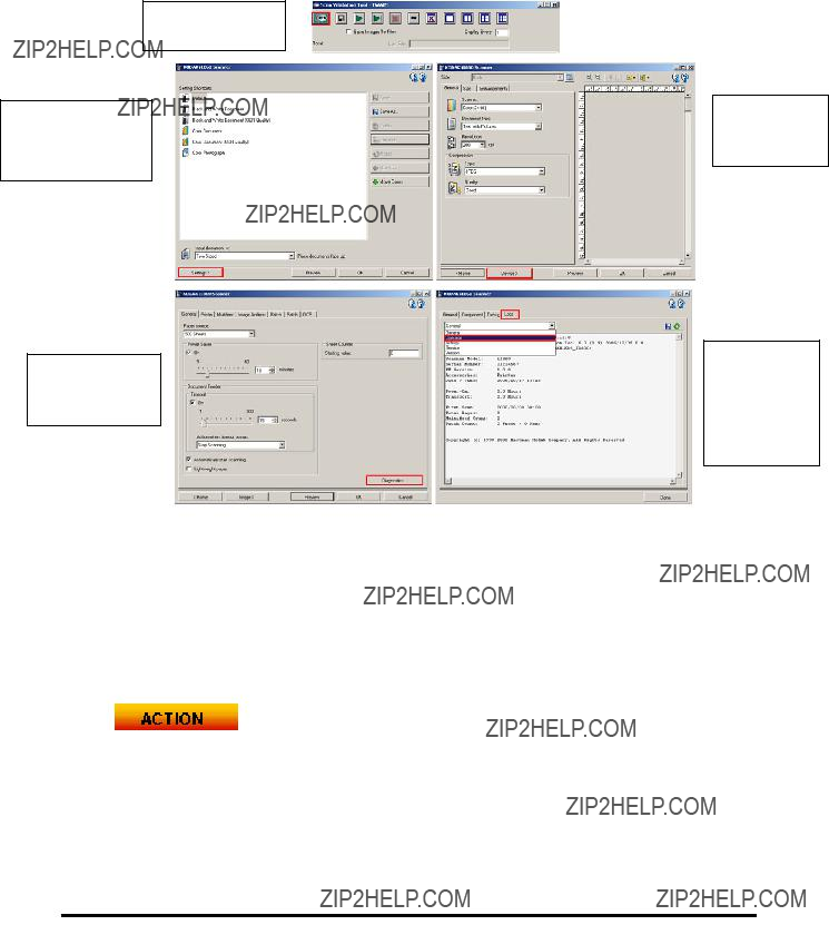
??Accessing the Scanner Log
To access the full Operator Log in the scanner from SVT follow these steps:
1.Click the SVT Setup button.
2.Click the
Settings button.
4.Click the
Diagnostics button.
3.Click the
Device button.
5.Click the
Logs tab and select
Operator Log.
NOTE: Operator Log entries with a date and time of 01/01/1970 00:00 are normal when the scanner is first turned on. The scanner uses this default time and date for all logs until the scanner can connect to a host computer and download the current local data and time.
[01/01/1970 00:00 docs=682] id=020 Power on self test completed [01/01/1970 00:00 docs=682] id=280 Lamps ready for scanning [01/01/1970 00:00 docs=682] id=359 Lamps not ready for scanning
Each student should launch the Scan Validation Tool and navigate to the full Operator Log.
TROUBLESHOOTING
As you operate the scanner, there may be problems that need to be corrected by the operator. This section covers the most common causes of scanner stoppages and how to correct them.
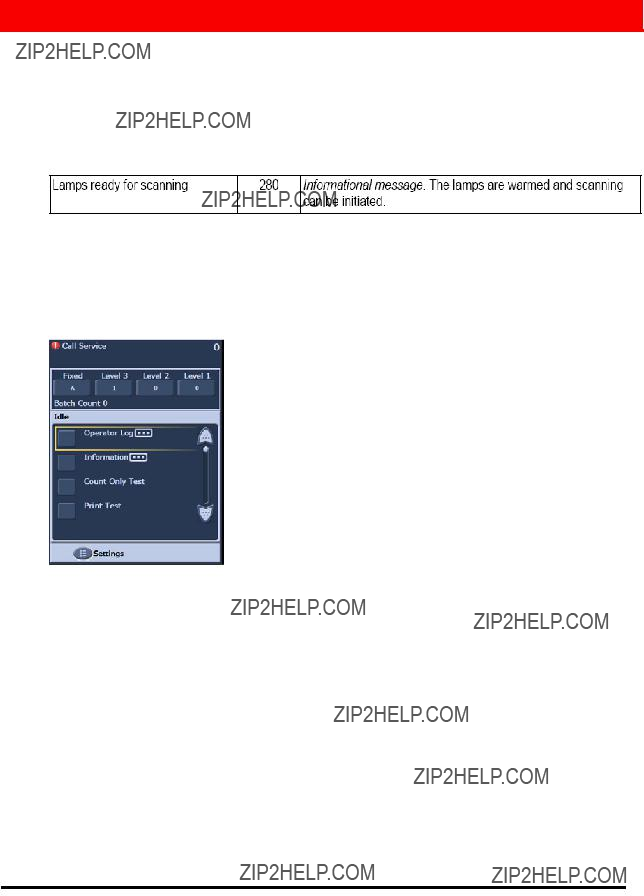
??Operator Control Panel Messages
There are many different messages that can be displayed on the Message window of the Operator Control Panel. To find more information on any of these messages refer to the section entitled, ???Message Listing??? in the User???s Guide, Chapter 6, Troubleshooting.
If a Call Service message is displayed, the scanner will need to be powered off and on before you can continue to scan. If the Call Service message is displayed again, the operator should write down the message code of the Call Service message in the Operator Log along with what action was being performed when the message was displayed (powering on/jam recovery/color scanning, etc.). Kodak Service should then be called.
??Document Jam Clearing
If a document fails to exit from the transport, the scanner will display a Jam In Transport message. To recover from a jam you should:
NOTE: The following procedure is a general guideline. Your procedure may be different depending on how your application is set up.
1.Remove the documents that have been scanned from the output tray.
2.Open the pod.
3.Remove any jammed documents from inside the transport.
4.Close the pod.
5.Verify the last document that was scanned correctly.
6.Place any documents that were not scanned at the top of the batch.
The scanner pod must be opened when clearing a jam to ensure that all paper has been cleared from the transport. There is no jog transport button. Note that there are different tones for a multifeed alert and a jam alert.
??Multifeed Messages and Alarms
The i1800 Series Scanner has three ultrasonic multifeed detectors in the transport.
These sensors use sound waves to determine if two or more documents go through the transport at the same time. The multifeed detection system can be set to one of three settings:
-Alarm only: the scanner transport will not stop if a multifeed is detected but only the alarm will sound.
-Alarm ??? Stop the transport and disable scanning: the scanner transport will stop if a multifeed is detected, the alarm will sound and the scanner will need to be re- started from the host before scanning can continue.
-Alarm ??? Stop the transport and keep the scanner enabled: the scanner transport will stop if a multifeed is detected and the scanner can be

There are two situations that can interrupt scanning that are related to multifeed messages.
??True Multifeed alarms: true multifeeds are experienced when more than one document is fed at a time. The following is a list of common causes and resolutions for this problem.
-The documents are physically stuck together.
??Check for a glue edge from a
??Check that stapled edges are not crimped together.
??Tear off edges can also bind together causing multifeeds.
??Pages that have been pressed together for long periods of time can often become stuck together.
The solution to this problem is spending more time in document preparation. The input stack must be fanned and folded in order to get an air gap between the pages.
-The documents are stuck together due to static.
Often pages of a stack of documents can become stuck together due to static adhesion. The best solution to this problem is to increase the humidity in the scanning area to help prevent the buildup of static.
-The documents are not all justified to the front of the stack.
If feeding
Again, careful document preparation is needed to correct this problem. If hand jogging is not sufficient to correct the problem, there are electric paper joggers that can be purchased.

-The consumables are worn or not installed properly.
If the
-The
The
-The
The bottom side of the black rubber strip on the
??False Multifeed alarms: False multifeed alarms are experienced when the ultrasonic multifeed detection systems triggers an alarm when there is only one document in the transport. The following is a list of common causes and resolutions for this problem:
-The page has a physical attachment.
If you are scanning a page that has ???sticky notes???, stickers (such as a barcode labels) or has a check taped to it, the multifeed detection system will trigger a multifeed alarm. If the attachments cannot be removed before scanning, and the attachments are all on one side of the document, the multifeed sensor for that area of the document may be disabled within the host software.
-The documents are very thick.
The ultrasonic multifeed detection system may trigger a false multifeed alarm when scanning a very thick document. If many of the documents to be scanned are thick, the sensitivity of the multifeed detection system can be set to LOW to prevent this problem. Note that some true multifeeds may not be detected with multifeed sensitivity set to LOW.
-The input stack contains folded pages or envelopes.
The ultrasonic multifeed detection system cannot distinguish between the two sides of an envelope or folder and a true multifeed of single pages. If envelopes or folders are being scanned, multifeed detection should be disabled or set to alarm only.
-The ultrasonic sensors are dirty.
The ultrasonic multifeed detection system may trigger a false multifeed alarm if paper or dust accumulates in the sensors. The sensors should be cleaned during maintenance.
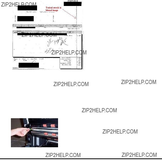
??Vertical lines
As was stated in the Maintenance section, ???The most frequent image quality problems that are reported with document feeding scanners are lines or streaks in the scanned image and black image borders, which are almost always caused by dust on the imaging components of the scanner.??? The i1800 Series Scanner was designed to minimize this problem but it can still occur if the image path is obstructed.
??Lines on the front images.
To correct this problem for the front side images, remove the upper imaging guide and thoroughly clean it using a Staticide wipe. For best results, the wipes should be allowed to dry out for a few seconds after removal from the packaging so they produce a clean streak free guide. Remember to clean the front and the back side of the imaging guide. After the imaging guide has been cleaned, it should be inspected for scratches. If the imaging guide is scratched, it must be replaced. Replace the imaging guide carefully without touching the glass areas.
??Lines on the rear images
To correct streaks on the rear side images, you must follow the same procedure, as previously noted, for the front imaging guide. The rear imaging guide is located in the base of the transport. Before
??Lines on front or rear black and white images (changing binarization settings.)
If you find that you need to frequently clean your scanner to prevent streaks in your black and white images then, consider modifying your ???conversion quality??? or binarization settings. If you are using the ???Best (iThresholding)??? setting (your scanning software may use a different name) then you may find that decreasing your Contrast value will greatly reduce the frequency of lines in your images.
??Large black borders on images or images look too small in the viewer.
The i1800 Series Scanner is normally setup to ???Automatically Detect and Straighten??? documents as they are being scanned. Your software may call this feature

If the black backgrounds of the scanner become scratched or dirty, so that they reflect light, then the Automatic Detect and Straighten feature of the scanner may incorrectly identify the edge of the page and leave a large black border on one side of the document. This problem may also be created by dust or debris that reflects light on the imaging guides or cover glass.
Examples:
D
This is what the same image (as shown in item C) would look like in a host scanner software image viewer that auto- sized the scanned image to fit in the viewer window.

SERVICE ISSUES
The information provided in this section is related to Service and Support in the United States and Canada only. Kodak provides Service and Support for our products in many countries around the world. For countries other than the United States and Canada, the instructor will provide you with the correct information for your local Kodak Service area.
As you operate the scanner, there may be problems that cannot be corrected by the operator. This section will cover everything you need to know about contacting Kodak Service.
Open the User???s Guide to Chapter 1, Contacting Service and Support. Phone numbers for the United States and Canada:
Kodak Field Service:
This number can be used to contact your local Field Engineer to schedule a site visit to correct a problem with the scanner or to schedule your next preventive maintenance visit.
Your Reseller: ________________________________
The Kodak Value Added Reseller will be glad to help you with many of your support needs. Write their phone number here so you will have it whenever you need to purchase Support Contract upgrades or other custom services they may offer.
Services:
Kodak has many professional services designed to help you be successful in your business. Call this number to inquire about additional scanner operator training, Kodak software application training or information about scanner relocation services.
??Contacting Service
There are a few things you can do to help Kodak Service assist you better when contacting us. Please have these items available when you make the call.
-Your Kodak Scanner???s
-Any error code numbers that may be in the Operator Log.
-A complete description of the problem.
-A contact name and phone number where the Field Engineer can return the call.
??Service Agreements and Upgrades
Your local Field Engineer can provide with you with the response time details and covered service hours for your scanner when it is under Warranty or covered by a Kodak Service Agreement. A standard Service Agreement includes two preventive maintenance visits per year. Upgrades for Service Contracts are also available. For additional details, talk with your Field Engineer or call the number previously listed for support services.
Each student should know where to find the
SAFETY
Open the User???s Guide to Chapter 1, Safety Information.
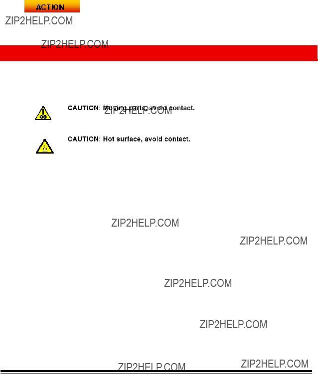
?? Warning Labels: Note all warning labels when operating and maintaining the scanner.
??User Precautions: Users and their employer need to observe the common sense precautions applicable to the operation of any machinery. These include, but are not limited to, the following:
-Do not wear loose clothing, unbuttoned sleeves, etc.
-Do not wear loose jewelry, bracelets, bulky rings, long necklaces, etc.
-Hair length should be kept short, using a hair net if needed, or tying long hair up in a bundle.
-Remove all other loose objects from the area that could be drawn into the machine.
-Take sufficient breaks to maintain mental alertness.
-Use only the recommended cleaning supplies.
-Do not use canned/compressed air.
Supervisors should review their practices and make compliance with these precautions as part of the job description for operation of the scanner or any mechanical device.
??Flammable Compressed Air and Cleaners: use of compressed air in the maintenance of the scanner is not recommended. Operators should NEVER use flammable compressed air or flammable cleaners when maintaining this equipment.

OTHER ISSUES
??Purchasing Consumables
Most Value Added Resellers (VARs) offer the recommended Kodak consumables for sale to their customers. If you need assistance in finding a channel for purchasing your consumables, talk with your instructor or Kodak Field Engineer.

Consumable Replacement Log for the Kodak i1800 Series Scanner
K#____________

Eastman Kodak Company 343 State Street Rochester, NY 14650 U.S.A.
?? Kodak, 2007. All rights reserved. TM: Kodak