Dolby Pro Logic & Dolby 3 Stereo
This surround system reproduces theater-like surround sound from video software marked 
 .
.
The PRO LOGIC mode uses the built-in directivity enhancer circuit to control the Left, Center, Right and Surround channel audio signals and reproduce a real sense of sound motion .
The 3 STEREO mode uses the directivity enhancer circuit to provide proper acoustic positioning and a real sense of sound motion even when only the front and center speakers are used.
New DSP surround modes
The DSP (Digital Signal Processor) used for this receiver incorporates a variety of high quality adjustable sound fields, like "ARENA", "JAZZ CLUB" and "STADIUM", to add the ???presence??? associated with an arena, jazz club or stadium to the original signal. It is compatible with almost any kind of program source.
Universal IR (InfraRed) remote control
In addition to the basic receiver operations, the remote control supplied with this receiver can also operate almost all of your remote controllable audio and video components. Just follow the simple setup procedure to register the components you have connected.???
Dual IR emitters
This remote control has two IR emitters: one to send commands in a straight line over long distances, allowing you to control the receiver and your other components from farther away; and one for wide dispersion of commands in a closer proximity, for near-field operation even when the remote control is not pointed directly at the respective component. #
MACRO play
The MACRO function lets you perform a series of operations automatically, like turning ON the power of the receiver and connected components, switching the input selectors, and starting playback. (Be sure to register your components before starting the macro set up procedure.)??q
FutureSet, automatic update feature (KR-V9090 only)
This function lets you update the remote control so it can operate new components which do not appear in the setup code list at the end of the manual. Therefore, the remote control will always be compatible.e
RDS (Radio Data System) tuner
The receiver is equipped with a RDS tuner that provides several convenient tuning functions: RDS Auto Memory, to automatically preset up to 40 RDS stations broadcasting different programs; station name display, to show you the name of the current broadcast station; and PTY search to let you tune stations by program type.??
PTY (Program TYpe) search
Lets you tune stations by specifying the type of program you want to hear.???
EON (Enhanced Other Networks) reservation
The EON function lets you monitor information on other stations so you can receive traffic, news, or information programs as soon as they are broadcast, even they are broadcast on a station different from the one you are currently listening to. When the broadcast ends, the receiver returns to the original station. When listening to Kenwood source components connected with system control cords, the input selector on the receiver automatically switches to the tuner when a program you desire is broadcast.??

 Specifications


 ??
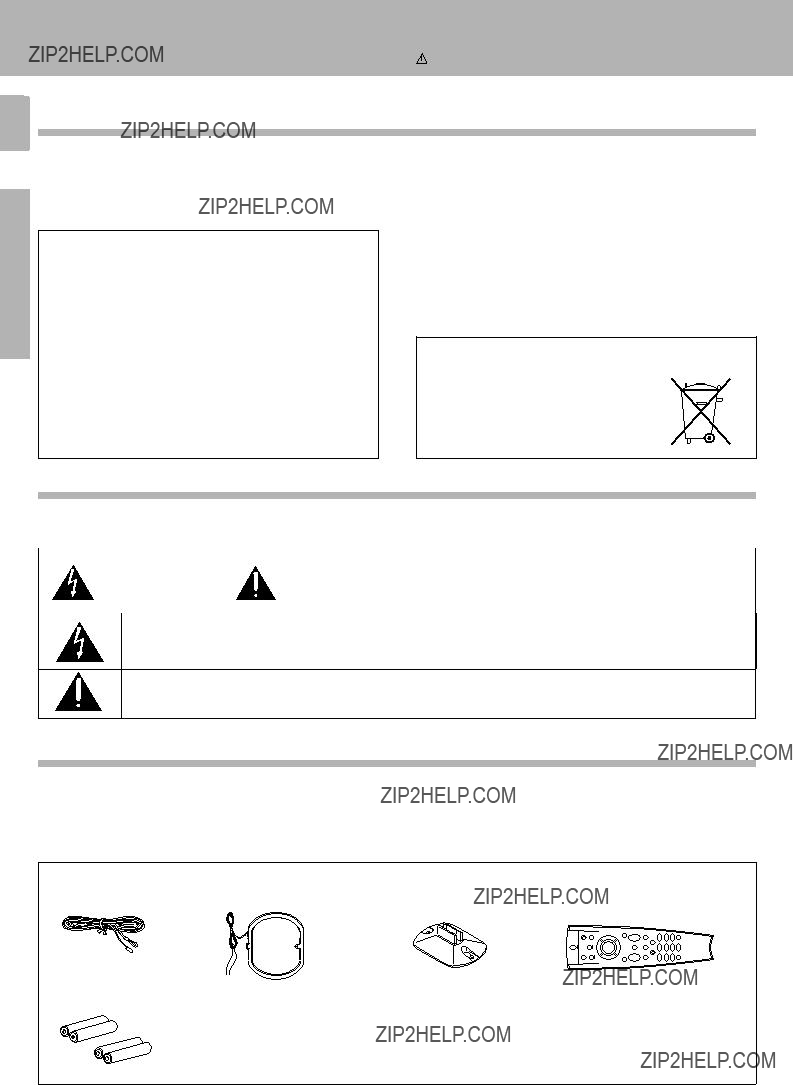
?? 2. Be sure to remove the power cord from the AC outlet before plugging or unplugging any connection cords. Plugging / unplugging connection Notes cords without disconnecting the power cord can cause malfunctions and may damage the unit.

 Mode : for
 terminals only


 --
--


 SP.
SP. 


 1
1 
 Some functions and function names may differ for certain Note countries and areas.
 1
1 


 ). This receiver is equipped with a Dolby Pro Logic surround decoder to let you enjoy the wide variety of currently available Dolby Pro Logic home video software.

 mark. DSP modes can be used with any source.
 \
\ \
\ \
\

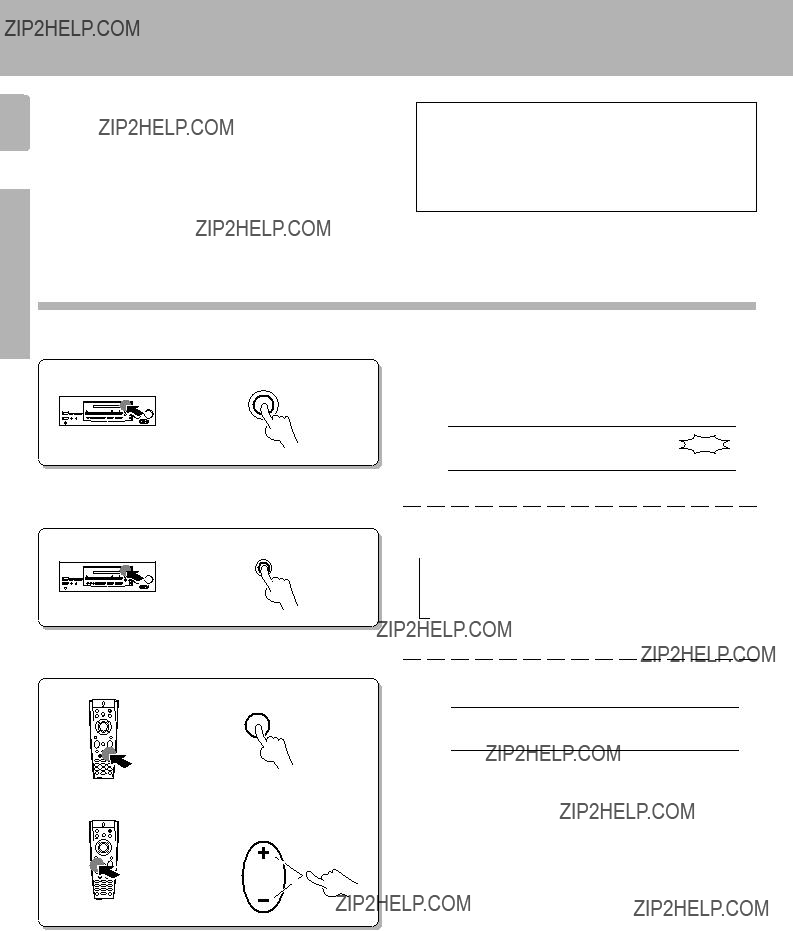
 Perform each of the following steps within
  5 seconds.


 Perform each of the following steps within
  5 seconds.


 Perform each of the following steps within
  5 seconds.


