KENWOOD NETWORK
COMMAND SYSTEM Setting Manual
?? March/29/2013
KENWOOD NETWORK
COMMAND SYSTEM Setting Manual
?? March/29/2013

Disclaimer:
All efforts have been made regarding the accuracy of the contents described in this document. However, there is a possibility of misprints and of descriptions that may cause misunderstanding. JVC KENWOOD Corporation bears absolutely no responsibility for damages arising thereof.
JVC KENWOOD Corporation may revise and amend the product information described in this document without notice. JVC KENWOOD Corporation bears absolutely no responsibility for damages arising thereof.
???Windows is a registered trademark or trademark of Microsoft Corporation in the United States and other countries.
???.NET Framework is a registered trademark or trademark of Microsoft Corporation in the United States and other countries.
???Bluetooth is a registered trademark or trademark of Bluetooth SIG, Inc.
???The names of all products described hereafter are the trademarks or registered trademarks of their respective manufacturers.
????? and ??? are omitted throughout the text.
1
1. Relevant Models
This operations guide is for the
Using the
KNS is a system configured using PCs, network environments,
Note: If the firmware version of the
Important
???To configure the system, knowledge not only of transceivers but also of PCs and networks is required. JVC KENWOOD does not offer support for customer PCs and Networks. Furthermore, for operations relating to actual transmitting, note that procedures according to the Radio Act are also required.
???Operations via networks may be delayed due to unavoidable principles. Consequently, do not perform operations (such as contests or
???Even if you set by the procedures described in this document, the feature may
not work properly because of the combination of PC, the network environment and the sound device.
???Refer to ???5. Limitations Caution!??? for other limitations.
???JVC KENWOOD Corporation shall bear no responsibility for related damage such as damage caused by missed communications and dialog opportunities due to incorrect customer settings, nonconformances, or misoperations as a result of using this document or the
2
2. Objectives of this document
To supply information to configure a remote control system via a home LAN or internet using the
Programs and Functions
3
3. Outline
3.1. Overall Configuration
??????3.1.1 ????????? LAN ????????????
???????????????????????????????????????????????????????????????????????????????????????????????????????????????
LAN
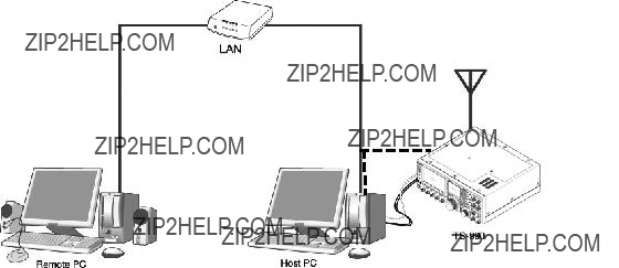
Fig. Example of a home LAN configuration
(In this diagram, the modem, router, and hub have been omitted.)
As shown in the diagram, the configuration uses a host station (where the transceiver is installed; this is called the "transmitter" in the Radio Act) and a remote station (which performs the remote operations; this is called the "operator" in the Radio Act). A PC is connected to both, and the PCs are connected to each other via the network.
The transceiver connected to the PC to which the
4
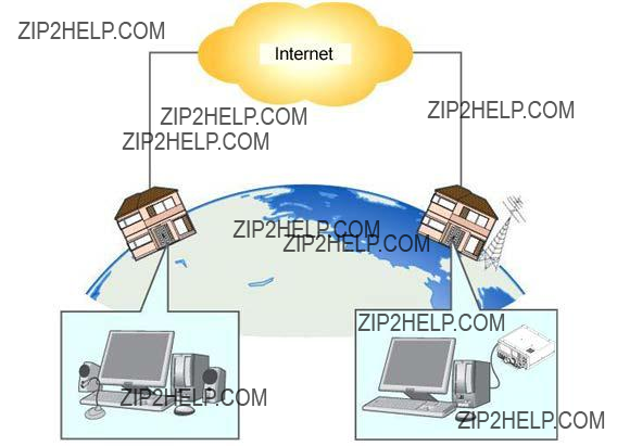
Fig. Example of a KNS configuration via the internet
The host station and remote station can be installed in any location with a home LAN connection or internet connection.
5
3.2. Outline of Host Station (Transmitter) Operations
The host station is configured using a transceiver and a PC connected to the network. Data signals that control the transceiver are connected to the PC using either LAN, USB or
The
The PC is connected to the network, and exchanges transceiver control data signals and audio transmissions with the "Remote station (operator)" on the network.
3.3. Host Station (Transmitter) Configuration
LAN/WAN (Commnunication with Remote Station)
LAN (Transceiver control)
6
7
Note 1: Other general purpose VoIP program can be used instead of the
Note 2: Refer to the user manual for the broadband router to be used before performing the settings.
Note 3: KNS operations are possible even if the global IP address is variable, but the IP address may change with uncertain timing. In such cases, it is necessary to check and change the IP address of the connected host when connected from a remote station, which reduces
8

3.4. Outline of Remote Station (Operator) Operations
The remote station is configured using a PC connected to the network, and a microphone and speaker connected to the PC sound function. The audio transmissions for the host station transceiver are input and output using the microphone and speaker connected to the sound function of the remote station PC via the network.
The
3.5. Remote Station (Operator) Configuration
LAN/WAN
(Communication with host station)
9
10
4. Settings
4.1. Connecting a Communications Cable
Connect the host station PC and
Note: The LAN cable,
???When connecting using a LAN cable
(1)Depending on the network environment you are using, connects the
(2)Setup the network functions (IP address, Administrator ID and password) of the
???When connecting using a USB cable
(1)Download the installer for the virtual COM port driver from the KENWOOD website: http://www.kenwood.com/i/products/info/amateur/software_download.html , then install it according to the procedures.
(2)Connect the PC and
???When connecting using an
Connect the PC and
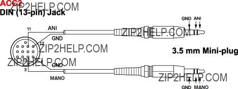
4.2. Connecting an Audio Cable
To transmit and receive audio, an audio cable is required. Create an audio cable using the
11
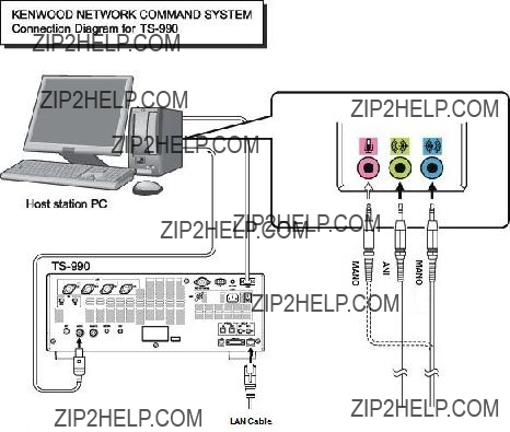
Connect the PC sound functions and audio cable with reference to the following diagram.
Reference:
If the
Delays also depend on the PC load and network traffic.
12
4.3. Transceiver Settings
Perform the required settings to implement KNS operations using transceivers.
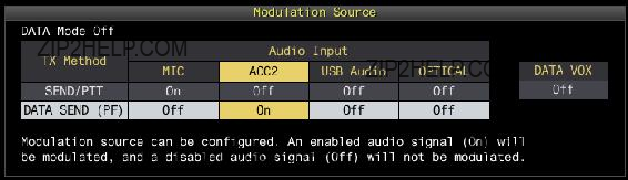
??? Set the transmitting audio input path settings
With KNS operations, normally transmitted audio is input from an ACC2 connector. Input is also possible using USB audio functions from a USB connector, but as the delays are great, this is not recommended.
On the Modulation Source screen of the
Modulation Source can be configured for each DATA mode (DATA Mode Off, DATA 1??? 3) that is currently selected.
Reference:
Set "USB audio" to ON, to be transmitted when "DATA SEND (PF)" is operated, to transmit USB audio signals input to the USB connector.
Set a playback device and recording device to the device connected to the
??? Data VOX settings
With the
Caution:
???When this function is ON, be aware that all sounds created by the PC other than the intended audio transmissions are also transmitted.
???When using this function for the first time, we recommend connecting a dummy load to the
13
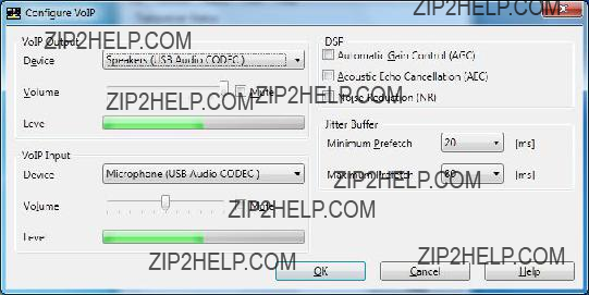
??? Audio I/O level settings
Use the following menu to adjust audio transmission input levels from the PC, and receive audio output levels to the PC.
Reference:
Adjust the Windows sound function volume as necessary.
??? Audio output configuration
In order to send both the main band audio and the sub band audio to the remote station using VoIP, perform the settings using the following menu.
Reference:
In the default setting (Normal), the received audio of the main band and the received audio of the
??? Mixed beep setting to external audio outputs
With the
Reference:
To implement data communications, set to ???Received Audio Only???.
14
??? Timeout timer settings
During KNS operations, control data signals are transmitted using the network. Consequently, if normal network operations are disabled for any reason, control of the transceiver will also be disabled. Use the following menu to set the functions to stop transmitting automatically after a fixed period if control should be disabled while transmitting.
??? Prohibit transmission setting
If using the host station as a
??? Allocating the DATA SEND function to PF keys
Set the DATA SEND function to the PF keys to test the transmission of audio input from the ACC2 connector or USB connector. In this example, the [PF A] key has been set.
Using the PF key, which has been set to the DATA SEND function, enables switching between transmit and receive modes for audio input from the ACC2 connector or USB connector.
15
4.4. Setting Transmission Methods for Audio Input to the ACC2 Connector
The PTT of the microphone connected to the
To transmit audio input as audio signals from the ACC2 connector, select one of the following methods.
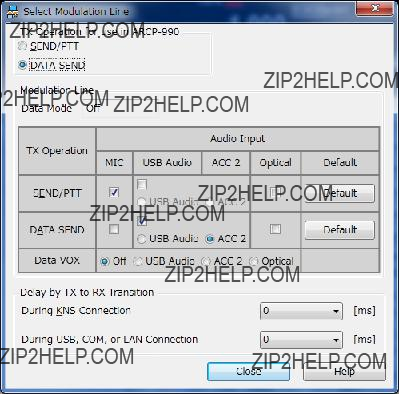
??? Transmitting using the
With the
Select "Select Modulation Line" from the
In this window, select "DATA SEND" under "TX Operation for use
For details, refer to the
??? Transmitting using the PKS terminal in the ACC2 connector
Audio input from the ACC2 connector can be transmitted by setting the PKS terminal in the ACC2 connector on the rear of the
For details of the connector and terminal specifications, refer to the
16
??? Transmitting using the PF keys allocated to the DATA SEND function
If the DATA SEND function has been allocated to a PF key, operating the PF key enables audio input from the ACC2 connector to be transmitted.
For details, refer to "Allocating DATA SEND Function to PF Keys".
17
4.5. Setting a Broadband Router
When implementing KNS operations via the internet, it is necessary to set the broadband router connected to the host station.
Perform the settings to transmit control data signals and audio transmissions via the internet from the broadband router to the host station PC.
This setting depends on the call method of the broadband router manufacturer, and may be "Port forwarding", "IP masquerade", "Port conversion", "NAT address conversion", etc. Refer to the user manual for the broadband router used.
The settings are described below.
Control data signals
Caution:
???For the broadband router settings, refer to the broadband router user manual.
???Incorrect broadband router settings may stop the network or enable illegal external access to the network. Take thorough precautions when changing the settings.
???JVC KENWOOD Corporation does not offer support for customer PCs and networks.
18
4.6. Software Installation and Settings
Install the software required for KNS operations on the host station PC and the remote station PC, then perform the required settings.
??? Host station PC
Download and install the
Connect the PC and
After starting the
Additionally, in "Configure KNS" in the "Tool" menu, set a user account, whether or not to use the VoIP function and others.
On the remote operation within the home LAN area, the VoIP function built into the
Caution:
??? Names in the selection of the device depend on the PC. For each setting, refer to the help file of the
On the remote operation via the internet, install the VoIP Program. If you select to use the
The
19
??? Remote station PC
Download and install the
After starting the
On the remote operation within the home LAN area, the VoIP function built into the
For the setting methods, refer to the
On the remote operation via the internet, install the VoIP Program. Install the same VoIP Program that was installed on the host station.
Caution:
On the remote operation via the internet, you can use a VoIP Program other than the
20
4.7. Windows Firewall Settings
With the host station PC, receiving connections from networks and the internet using the
Reference:
Add the
4.8. Comprehensive Security Software Settings
If using comprehensive security software, it is necessary to adjust the settings so that
4.9. Making the Host Station Connection Request Wait Mode
Click the "Connect" button in the main window of the
If you are using the
4.10. Connecting to the Host Station from the Remote Station
Click the "Connect" button in the main window of the
If you are using the
21
5. Limitations Caution!
5.1. PC Environment Limitations
Check that the
For KNS operations, it is necessary to set and change the open broadband router port, Windows firewall functions, and comprehensive security software. Furthermore, it is the customer's responsibility to handle security when using this system. If you do not have confidence in the settings, we recommended you stop using the system.
5.2. Network Environment Limitations
During KNS operations via the internet, it is necessary to set the global IP address on the host station. For your global IP address, consult your contracted provider.
Only registered people can access the host station using their ID and password. Make sure that the ID and password settings cannot be guessed easily by unauthorized people.
On this system, signals are exchanged via the network. Consequently, smooth operations may be disabled compared to normal transceiver operations, as delays (during analog/digital conversions) and data loss (which is greatly dependent on traffic) are unavoidable. This is the principle operation of the system.
Examples are cited below.
Audio may break up, meter deflection may not be smooth, standby time may be delayed (in particular, it is not suitable for contests or quick operations such as
Broadband is recommended for the internet line used. As a benchmark, use a minimum of 1 Mbps. The speed of analog modems that use telephone lines will greatly reduce sound quality, and may destabilize control, and so cannot be used.
22
5.3. Program Limitations
CW operations are possible, but keying using normal
5.4. Limitations if Using USB Audio Functions
If the PC and
If audio transmissions are connected via a USB connection, and if playing warning sounds from the Windows or music and video on the PC, the sounds may not emit from the PC speakers.
Furthermore, depending on the Windows sound settings, the transceiver DATA VOX function settings, and the modulation path, audio may be modulated from the transceiver; take care during PC operations and when playing music and video.
Depending on the combination of PC and sound functions, normal operations may be disabled.
JVC KENWOOD does not offer support for customer PCs.
We recommend using an audio cable without using USB audio functions for KNS operations. (Refer to "4.2. Connecting an Audio Cable".)
23
6. Frequently Asked Questions
This section introduces questions that have been asked to date, and subjects verified by JVC KENWOOD Corporation.
24
25
26
27
28
29
30
31

(Supplement): FAQ: Explaining the Internet "Cannot operate transceiver"
Internet
Fig. 1
As shown in Fig. 1, even though only one broadband router (BBR) is visible on the network, in reality there are two. (Duplex router phenomenon.)
There are multiple modems with
Consequently, even if the open port has been set for one BBR only, the required KNS packets will not flow. For this reason, either set the required KNS port to open for both BBRs, or stop one BBR function, and set the network so that there is only one BBR on the network.
Fig. 2
As shown in Fig. 2, the case where a telephone is connected directly to a modem, in most models the modem has a
To prevent the VoIP telephone functions from stopping, stop the functions of the BBR connected to the front of the PC, and set the port required by KNS to open in the BBR built into the modem.
32
Caution:
Change any settings such as open BBR ports at your own risk.
If you do not have confidence in the settings, we recommend you stop using the system.
33