Serial number

WIDE SCREEN MONITOR

LZ-651W

INSTRUCTION MANUAL

Take the time to read through this instruction manual.

Familiarity with installation and operation procedures will help you obtain the best performance from your new LZ-651W.

For your records

Record the serial number, found on the back of the unit, in the spaces designated on the warranty card, and in the space provided below. Refer to the model and serial numbers whenever you call upon your KENWOOD dealer for information or service on the product.

Model

?? PRINTED IN JAPAN B64-2631-00/00 (E/K)

English

Before Use

Safety Precaution

2WARNING

To prevent injury and/or fire, take the following precautions:

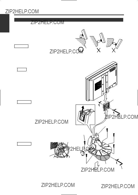
???Ensure that the unit is securely installed. Otherwise it may fly out of place during collisions and other jolts.

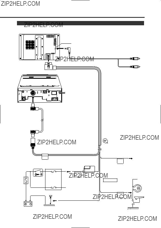
???When extending the ignition or ground cables, make sure to use automotive-grade cables or other cables with an area of 0.75mm2 (AWG18) or more to prevent wire deterioration and damage to the wire coating.

???To prevent short circuits, never put or leave any metallic objects (e.g., coins or metal tools) inside the unit.

???If the unit starts to emit smoke or strange smells, turn off the power immediately and consult your Kenwood dealer

???Do not touch the liquid crystal fluid if the LCD is damaged or broken due to shock. The liquid crystal fluid may be dangerous to your health or even fatal.

If the liquid crystal fluid from the LCD contacts your body or clothing, wash it off with soap immediately.

This video unit is set for rear passenger use only.

Use of this video unit in any front seat and/or where it may be visible to the driver may be illegal in some states and may cause driver distraction and accident which could injure or kill you.

2CAUTION

To prevent damage to the machine, take the following precautions:

???Make sure to ground the unit to a negative 12V DC power supply.

???Do not open the covers of the unit.

???Do not install the unit in a spot exposed to direct sunlight or excessive heat or humidity. Also avoid places with too much dust or the possibility of water splashing.

???Do not subject the monitor unit to excessive shock, as it is a piece of precision equipment.

???When replacing a fuse, only use a new one with the prescribed rating. Using a fuse with the wrong rating may cause your unit to malfunction.

???To prevent short circuits when replacing a fuse, first disconnect the wiring harness.

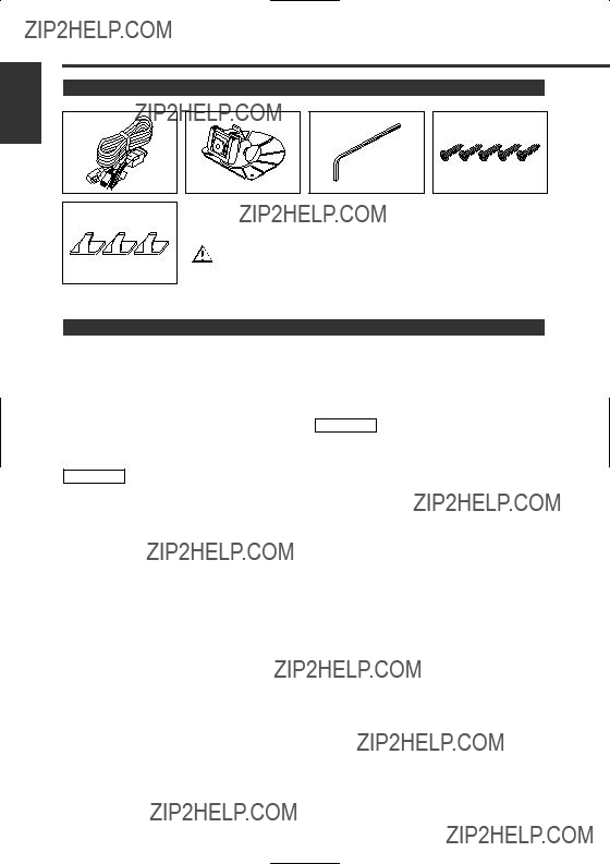
???Do not use any screws except for the ones provided. The use of improper screws might result in damage to the main unit.

???You cannot view video pictures whilst the vehicle is moving. To enjoy video pictures, find a safe place to park and engage the parking brake.

???Keep a cellular phone or other things that oscillate high frequency away from this unit. If not, the picture of the monitor may be distorted or noises may occur.

NOTE

If you experience problems during installation, consult your Kenwood dealer.

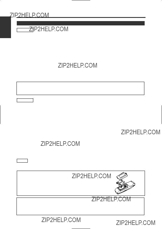
If the remote control should become unresponsive, replace with new batteries (i.e., 2 x R03).

Make sure that the batteries are inserted in the correct direction, and do not use old batteries together with new ones.

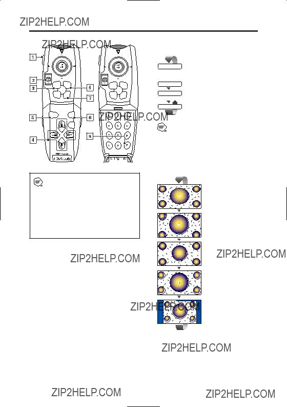
The illustrations of the display and the panel appearing in this manual are examples used to explain more clearly how the controls are used. Therefore, what appears on the display in the illustrations may differ from what appears on the display on the actual equipment, and some of the illustrations on the display may represent something impossible in actual operation.
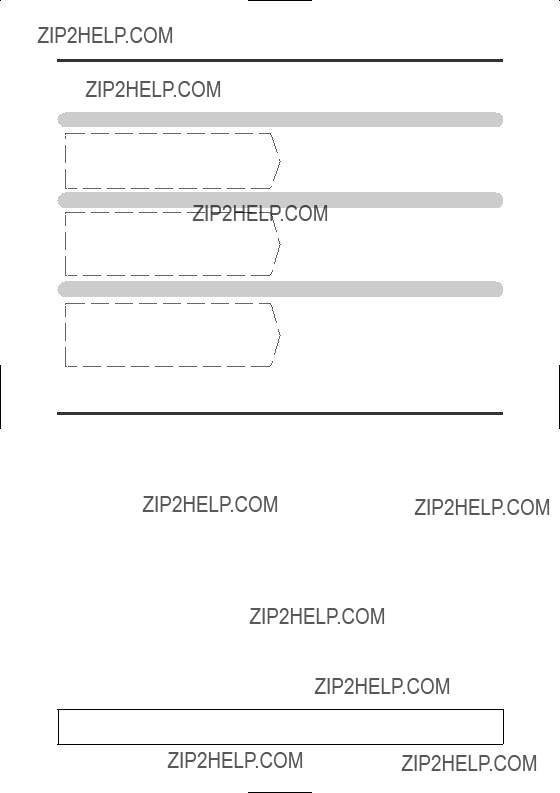
2 English

LZ-651W Basic Operation

BAND DISC

MON

NAVI

AUD

OUT

8Audio Source Select button

Each time the button is pressed the audio source switches as follows:

NORMAL Sound of monitoring picture selected by [Video Source Select] button.
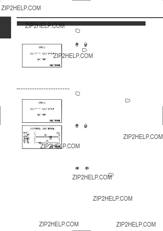
NAV Sound of navigation system.

AV-IN Sound of input video picture from AV-IN.

OFF No sound.

When the voice guidance event for the navigation system takes place, the audio source switches temporarily to the sound used by the navigation system even with the sound through the AV-IN being output.

9Screen Mode Select button

Each time the button is pressed the screen mode switches as follows.

Set Mode Setting switch to "MON" position while operating this LCD monitor. Refer to the instruction manual for the operation of the navigation system.

Display the setup screen for 5 seconds as follows:

???Screen mode

???Video source

???Audio source

???Volume

1 Mode Setting switch

Selects the target device to control. MON: Monitor control mode

NAVI: Navigation system control mode

AUD: Kenwood car audio system control mode

2 Volume Control button

3 Power button

4Cursor button

Selects the item when the menu screen is displayed.

5Enter button

Performs selected item when the menu screen is displayed.

6Menu Display button

Displays the menu screen. (page 4)

7Video Source Select button

Each time the button is pressed the monitor???s picture switches as the navigation picture or the video picture set to "AV-IN".

[FULL]

[ZOOM]

[JUST]

[CINEMA]

[NORMAL]

English 3

English

Setup Menu

Setting Menu

mode.

Also, the monitor exits from Menu mode by no opeation for 10 seconds.

4 English

Setup

1

2

3

MENU

Press MENU button.

Press or button to select the adjusting item.

"NAV": Setup input and switch method of the navigation

*Default setting

If you set to "OFF" while the audio source is set to "NAV", the audio source would switch to "NORMAL".

"AV-IN": Setup switch method of the picture input to AV-

*Default setting

4

5

You cannot set "AV-IN" when "NAV" is set to "AV-IN".

If you set to "OFF" while the audio source is set to "AV-IN", the audio source would switch to "NORMAL".

"BEEP": Setup the beep sound ON/OFF.

*Default setting

Press or button to select each item.

Also, the monitor exits from Menu mode by no opeation for 10 seconds.

English 5

English

The use of any accessories except for those provided might result in damage to the unit. Make sure only to use the accessories shipped with the unit, as shown above.

Installation Procedure

1.To prevent short circuits, remove the key from the ignition and disconnect the ?? terminal of the battery.

2.Make the proper input and output cable connections for each unit.

3.Connect the wiring harness cables in the following order: ground, ignition.

4.Connect the wiring harness connector to the unit.

5.Install the unit in your car.

6.Reconnect the - terminal of the battery.

2WARNING

???This product is intended for use with 12V DC negative ground power only. Do not connect it to any other power supply

???To prevent shorting, disconnect the battery cable from the negative terminal of the battery during installation.

???Be sure to firmly stabilise this product. Do not install it in a location which is not stable.

???Follow the installation and wiring procedures described in this manual. Improper wiring or modified installation can not only result in malfunction or damage to the unit but may also result in an accident.

???Do not install the unit in the following locations.

???A location which interferes with the operation of the air bag system.

???A location which is not made of plastic.

\Installing on leather, wood or cloth may damage the surface.

???A location subject to direct sunlight, subject to the air from the air conditioner, or subject to moisture or high temperature.

\This may cause deformation of the monitor unit.

???Be sure to use the supplied screws for installation.

Using screws longer than those supplied may destroy parts inside the unit causing it to smoke. Using screws shorter than those supplied may cause the unit to come looks from

the installation bracket.

???If you are not going to install the unit using the supplied monitor stand, be sure to use a commercially available monitor stand. (Mounting holes for such a stand are located on the bottom of the monitor unit.)

2CAUTION

???If your car's ignition does not come with an ACC position, connect the ignition cables to a power source that can be turned on and off with the ignition key. If you connect the ignition wire to a power source that receives a constant voltage supply, as with battery cables, the battery may die.

???If the fuse blows, first make sure that the cables have not caused a short circuit, then replace the old fuse with one with the same rating.

???Do not let unconnected cables or terminals touch metal on the car or anything else conducting electricity. To prevent short circuits do not remove the caps from unused terminals or from the ends of the unconnected cables.

???After the unit is installed, check whether the brake lamps, blinkers, wipers, etc. on the car are working properly.

???Insulate unconnected cables with vinyl tape or other similar material.

???Thoroughly wipe away oil and other dirt from the installation surface. Please avoid installation on uneven surfaces.

6 English

Connection

Monitor Unit

AV input

Bundle cables with the clamper (Accessory A)

Cable accompanying the Navigation System

Car fuse box (Main fuse)

NAVI

Ground cable (Black) -

To car crassic

Battery

When you connect the Mute Cable to the Navigation System, the voice of the Navigation guide will interrupt.

Mute cable (Brown)

MUTE

Connect TEL mute cable of the navigation system.

For the sake of safety, be sure to connect the parking sensor.

PRK

SW

Parking sensor cable (Green)

English 7

Installation

English

Installation for Monitor Unit

Installation location and cleaning

Select for installation a location where the stand can be placed completely horizontal or where the front edge of the support (petal-shaped part) can be attached horizontally as shown in Figure A.

Do not install in locations where the entire support is at a diagonal such as in Figure B or where the monitor unit is facing down such as in Figure C.

2CAUTION

Thoroughly wipe away and dust or grease from the installation location using a cloth which has been soaked in a neutral cleaning agent and wrung out. Attach the stand after allowing the installation location to dry.

1Install the shoe on the rear of the TV monitor

temporarily using the supplied hexagon wrench (Accessary C).

NOTE

When adjusting the fixing screw of the shoe, use the hexagon wrench (Accessary C) that came with the product. Using other hexagon wrenches may damage the screw.

2Bend the stand support to conform to the shape of the installation location.

3Adjust the shape of the support so that there is no rattling or gap when the stand is placed on the support.

4Peel off the protective strip from the double-sided tape on the bottom of the stand and securely attach the stand.

2CAUTION

???Do not attach the double-sided tape more than once or touch the adhesive with your fingers as this will weaken its adhesive strength.

???If the temperature of the surface of the installation location is low, warm it up using a heater or other means before attaching the stand. Low temperature may weaken the adhesive strength of the tape.

???The supplied stand is specially intended for this product. Do not use it with another monitor.

5Secure the stand using the supplied tapping screw (Accessory D).

6After attaching the stand, allow it to sit undisturbed for 24 hours. Take care not to apply any force to the stand during this time.

7Insert the shoe of the monitor unit into the bracket (Accessory B).

2CAUTION

Insert the shoe into the bracket (Accessory B) as far as it goes.

8Adjust the height, horizontal and vertical angle of the monitor unit, and securely tighten the installation

screws using the supplied hexagon wrench (Accessary C).

You can also adjust the monitor unit's forward position by loosening the angle adjustment knobs and adjusting the angle of the monitor unit's installation stand.

A BC

Shoe

Accessory C

Accessory B

Accessory D

Tighten

Loosen

Protective strip

Accessory C

Installation surface

8 English

Troubleshooting

What might appear to be a malfunction in your unit may just be the result of slight misoperation or miswiring. Before calling service, first check the following table for possible problems.

The power does not turn on.

???The fuse has blown.

???No ACC position on vehicle ignition.

No video picture appears.

???The unit is not connected to the parking brake detection switch.

???The parking brake is not engaged.

The screen is dark.

???The unit is in a location where temperature is low.

???After checking for short circuits in the cables, replace the fuse with one having the same rating.

???Connect the same cable to the ignition as the battery cable.

???Make proper connections according to "Connection".

???For safety reasons no video picture are displayed while the vehicle is moving. Engaging the parking brake will cause picture to be displayed.

???If the temperature of the monitor unit drops, the screen may appear darker when power is first turned on due to the characteristics of a liquid crystal panel. Wait a while after turning power on for the temperature to rise. Normal brightness will return.

Specifications

Although the effective pixels for the liquid crystal panel is given as 99.99% or more, 0.01% of pixels may not light or may light incorrectly.

English 9

English

FCC WARNING

This equipment may generate or use radio frequency energy. Changes or modifications to this equipment may cause harmful interference unless the modifications are expressly approved in the instruction manual. The user could lose the authority to operate this equipment if an unauthorized change or modification is made.

NOTE

This equipment has been tested and found to comply with the limits for a Class B digital device, pursuant to Part 15 of the FCC Rules. These limits are designed to provide reasonable protection against harmful interference in a residential installation. This equipment may cause harmful interference to radio communications, if it is not installed and used in accordance with the instructions. However, there is no guarantee that interference will not occur in a particular installation. If this equipment does cause harmful interference to radio or television reception, which can be determined by turning the equipment off and on, the user is encouraged to try to correct the interference by one or more of the following measures:

???Reorient or relocate the receiving antenna.

???Increase the separation between the equipment and receiver.

???Connect the equipment into an outlet on a circuit different from that to which the receiver is connected.

???Consult the dealer or an experienced radio/TV technician for help.

NOTE

This Class B digital apparatus complies with Canadian ICES-003.

10 English