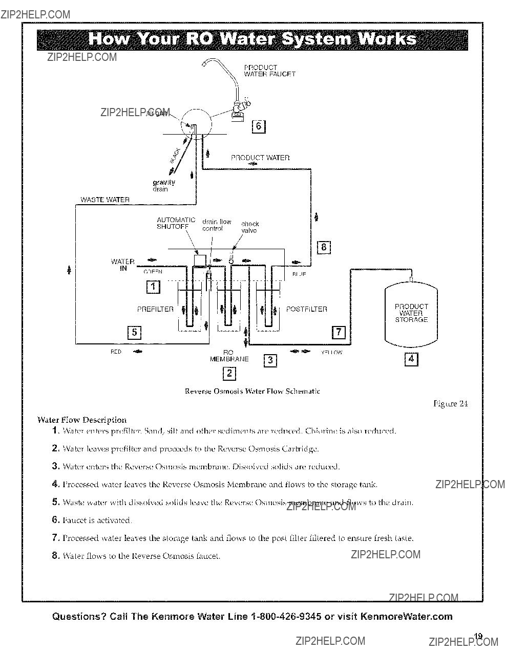
OWNER'S MANUAL

Osmosis

MODEL NO. 625.381560

UltraFilter 450

Caution:

Read and follow all safety rules and operating instructions before first use of this product.

Questions ?

Visit www.KenmoreWater.com

or call toll free 1-800-426-9345 (M - F,7AM - 8 PM CST)

Repair or Paris ? Call toll free 1=800469=4663

See back cover for other Sears service numbers.

SAVE THiS MANUAL

???Warranty

???Installation

???How ItWorks

???Care Of

???Specifications

???Repair Parts

System Tested and Certified by NSF International against NSF/ANSI

Standard 42 and 58. See performance data sheet for details.

Sears, Roebuck and Co., 3333 Beverly Road, Hoffman Estates, IL 60179 U.S.A.

ONE YEAR FULL WARRANTY ON REVERSE OSMOSIS SYSTEM

When installed, operated and maintained according to all instructions supplied with the product, if this Reverse Osmosis System fails due to a defect in material or workmanship within one year from the date of purchase, call 1=800=4=MY-HOME to arrange for free repair (or replacement if repair proves impossible).

This warranty does not include filter cartridges or the Reverse Osmosis membrane, which are expendable items.

This warranty applies only while this product is in use in the United States or Canada.

This warranty gives you specific legal rights, and you may have other rights which vary from state to state.

Sears, Roebuck and Co., Hoffman Estates, IL 60179

Y

14"

Questions? Call The Kenmore Water Line 1-800-426-9345 or visit KenmoreWater.com

Y Read all steps and guides carefully before installing and using your reverse osmosis system. Follow all steps exactly to correctly install. Reading this manual will also help you to get all the benefits from the reverse osmosis system.

V Do not attempt to use this product to make safe drinking water from non-potable water sources. Do not use the system on microbiologically unsafe water, or water of unknown quality without adequate disin- fection before or after the system. This system is certi- fied for cyst reduction and may be used on disinfec- ted water that may contain filterable cysts.

Y Check with your local public works department for plumbing and sanitation codes. You must follow their guides as you install the system. Follow your local codes if they differ with guides in this manual.

Y This system shall only be used for arsenic reduction on chlorinated water supplies containing detectable residual free chlorine at the system inlet. Water sys- tems using an inline chlorinator should provide a one minute chlorine contact time before the RO system.

V This system is acceptable for treatment of influent concentrations of no more than 27 mg/L nitrate and 3 mg/L nitrite in combination measured as N and is cer- tified for nitrate/nitrite reduction only for water sup- plies with a pressure of 280 kPa (40 psig) or greater.

Y The reverse osmosis system works on water pressures of 40 psi (minimum) to 100 psi (maximum). if your house water pressure is over the maximum, install a pressure reducing valve in the water supply pipe to the reverse osmosis system.

Y Do not install the reverse osmosis system outside, or in extreme hot or cold temperatures. Temperature of

the water supply to the reverse osmosis system must be between 40??F and 100??F. Do not install on hot

water.

V Read the other limits (pH, hardness, etc.) in the speci- fications and be sure your water supply conforms.

V The reverse osmosis membrane contains a preserva- tive for storage and shipment. Be sure to purge as instructed on page 17 before using product water.

Questions? Call The Kenmore Water Line 1-800-426-9345 or visit KenmoreWater.com

INSPECT SHIPMENT

Your Reverse Osmosis Drinking Water System is shipped complete in one carton. Remove all items from your shipping carton.

Check all items against the packing list below. Note any items lost or damaged in shipment. Note any damage to the shipping carton. Refer to the exploded view and parts list in the back of the manual for the part names and numbers of missing or damaged items. If problems exist, refer to the website or the toll free number listed throughout this manual.

Keep the small parts in the parts bag until you are ready to install them.

NOTE: Codes in the state of Massachusetts require installation by a licensed plumber and do not permit the use of saddle valves.

if you live in the state of Massachusetts, review plumb- ing code 248-CMR of the Commonwealth of Massachusetts before proceeding with the installation.

Bag Assembly

0

0

Bag Assembly

??

Coin

Battery

Reverse Osmosis Faucet Assembly with black and blue tubes attached

Questions? Call The Kenmore Water Line 1-800-426-9345 or visit KenmoreWater.com

Your Reverse Osmosis (RO) Drinking Water System is a water treatment unit. It uses household water pressure to reverse a natural physical process called osmosis. Water, under pressure, is forced through a semi-permeable membrane where minerals and impurities are filtered

out. Clean drinking water goes to the faucet or storage, while minerals and impurities are sent to the drain with RO waste water. The minerals and impurities are meas- ured in water as total dissolved solids (TDS).

The system includes replaceable pre and postfilter sedi- ment-carbon cartridges. The prefilter reduces sand, silt, dirt, rust particles, other sediments, and chlorine from the water supply before it can enter the RO membrane.

PLAN YOUR INSTALLATION

it is recommended to read through the entire manual before beginning your installation. Follow all steps exact- ly. Reading this manual will also help you get all the benefits from your system.

Your Reverse Osmosis Drinking Water System can be installed under a sink or in a remote location. Typical remote sites are a laundry room or utility room. Review the location options below and determine where you are going to install your system.

NOTE: For best system performance, the feed water to the system should be softened or less than 10 grains per gallon hard,

UNDER THE SINK LOCATION

The Reverse Osmosis Filter Assembly and storage tank are normally installed in a kitchen or bathroom sink cab- inet. See Figure 2.

A suitable drain point is needed for reject water from the Reverse Osmosis filter.

REMOTE LOCATION

You can also locate the Reverse Osmosis Filter Assembly and storage tank in a remote location away from the Reverse Osmosis Faucet. You will need a nearby water source and drain point.

See Figure 3.

CHECK SPACE REQUIREMENTS

Check size and position of items for proper installation into location chosen.

TOOLS NEEDED

Review the tools needed list. See Figure 1. Gather need- ed tools before proceeding with the installation. Read

and follow the instructions provided with any tools list- ed here.

The postfilter reduces any tastes and/or odors that may remain in the water, after passing through the RO mem- brane, and just before going to the RO faucet. To prevent water waste, an automatic shutoff valve closes when the RO faucet is closed and the storage tank is full.

Your reverse osmosis system gives you a continuous supply of sparkling clear, delicious water for drinking, cooking and other uses. Foods will look and taste better too. Having high quality RO product water at your fin- gertips eliminates the need to buy bottled water. The storage tank holds over 2 gallons of RO product water for your needs.

Tools Needed

Adjustable Wrench

Phillips Screwdriver

_12pe Measure

S

Large Adjustable Jaw Pliers or Pipe Wrench

Figure

Questions? Call The Kenmore Water Line 1-800-426-9345 or visit KenmoreWater.com

Typical Under Sink Installation

j/J

! ! Sink Drain P-_lrap \_

Figure 2

Typical Remote

Outside Faucet

(Hard Water)

Soft, Cold Water

Soft, ttot

Water

Sediment

Filter

Water

Softener

Additional Parts required.

Installation

Reverse

Osmosis

System

I

Storage _12mk

Water

Meter

Air Gap Main

Shutoff

Valve

Figure 3

Questions? Call The Kenmore Water Line 1-800-426-9345 or visit KenmoreWater.com

OVERVIEW

There are seven easy steps to installing your Drinking

Water system. They are as follows:

STEP 1 - install Cold Water Supply fitting

STEP 2 - install Drain Adapter

STEP 3 - install Reverse Osmosis Assembly

STEP 4 - install Storage Tank

STEP 5 - install Reverse Osmosis Faucet

STEP 6 - Connect Tubing

STEP 7 - Sanitize, Pressure Test, Purge System

These steps are explained in detail over the next few

pages.Figure 4 it is recommended to read through the entire manual

before beginning your installation. Follow all steps exact- ly. Reading this manual will also help you receive and use all the benefits your Reverse Osmosis System can give you.

PREPARE SITE FOR INSTALLATION

1.Before starting, close the hot and cold water shutoff valves (See Figure 5).

2.Temporarily place tank and filter assembly into cabi- net. Double check position of items and space required for proper installation.

3.Remove tank and filter from cabinet and set aside.

NOTE: You must check and comply with all local plumbing codes.

Questions? Call The Kenmore Water Line 1-800-426-9345 or visit KenmoreWater.com

CHOOSE TYPE OF WATER FITTING TO

INSTALL

Locate the cold water line in the sink cabinet. It is recom- mended, but not required, that the cold water line be soft water. You can use the saddle valve provided with your unit to tap into the cold water line. See Fig. 5. Or you can purchase standard pipe fittings locally such as a com- pression fitting. The fitting must provide a leak-tight connection to the Reverse Osmosis 1/4" tube.

NOTE: Local code may dictate which type of water fit- ting is used. Consult a plumber if you are not familiar with local codes or plumbing procedures.

NOTE: Codes in the state of Massachusetts require installation by a licensed plumber and do not permit the use of saddle valves.

If you live in the state of Massachusetts, review plumb- ing code 248-CMR of the Commonwealth of Massachusetts before proceeding with the installation.

INSTALL SADDLE VALVE

(Included with your package)

6.Do not connect the tubing to the fitting at this time. This will occur later in the installation.

NOTE: Once the saddle valve is installed, the nut near

the handle may need to be tightened to prevent possi- ble leaks.

\

t

Z

This fitting will be installed on the cold water pipe. The fitting must provide a leak-tight connection to the Reverse Osmosis 1/4" tubing.

Complete the following steps to install the saddle valve assembly.

. Review Fig. 5 and familiarize yourself with all parts of the saddle valve. This valve will self-tap a hole in cop- per tubing or plastic pipe.

IMPORTANT'. Before starting, close the hot and cold water shutoff valves (See Figure 5).

2.if installing on iron pipe, drill a 1/8" hole for the pierc- ing pin.

IMPORTANT'. if a battery-powered hand drill is not available and an electric drill is used, ensure that the

drill is properly grounded.

Pre-Drill

1/8" Hole

(Iron Pipe)

Seal

_X

Valve

Nut - tighten if necessary

. Place the seal on the inside of Clamp X. See Fig. 5. Turn the valve handle all the way out.(counter-clock- wise) Be sure the piercing pin does not stick out beyond the seal.

Clamp Z

(Plastic)

Insert

Handle

Tubing

Saddle Valve Connection

(Included in package)

Figure 5

Questions? Call The Kenmore Water Line 1-800-426-9345 or visit KenmoreWater.com

INTRODUCTION

A suitable drain point is needed for the reject water from

the Reverse Osmosis Filter. You have two options to choose from:

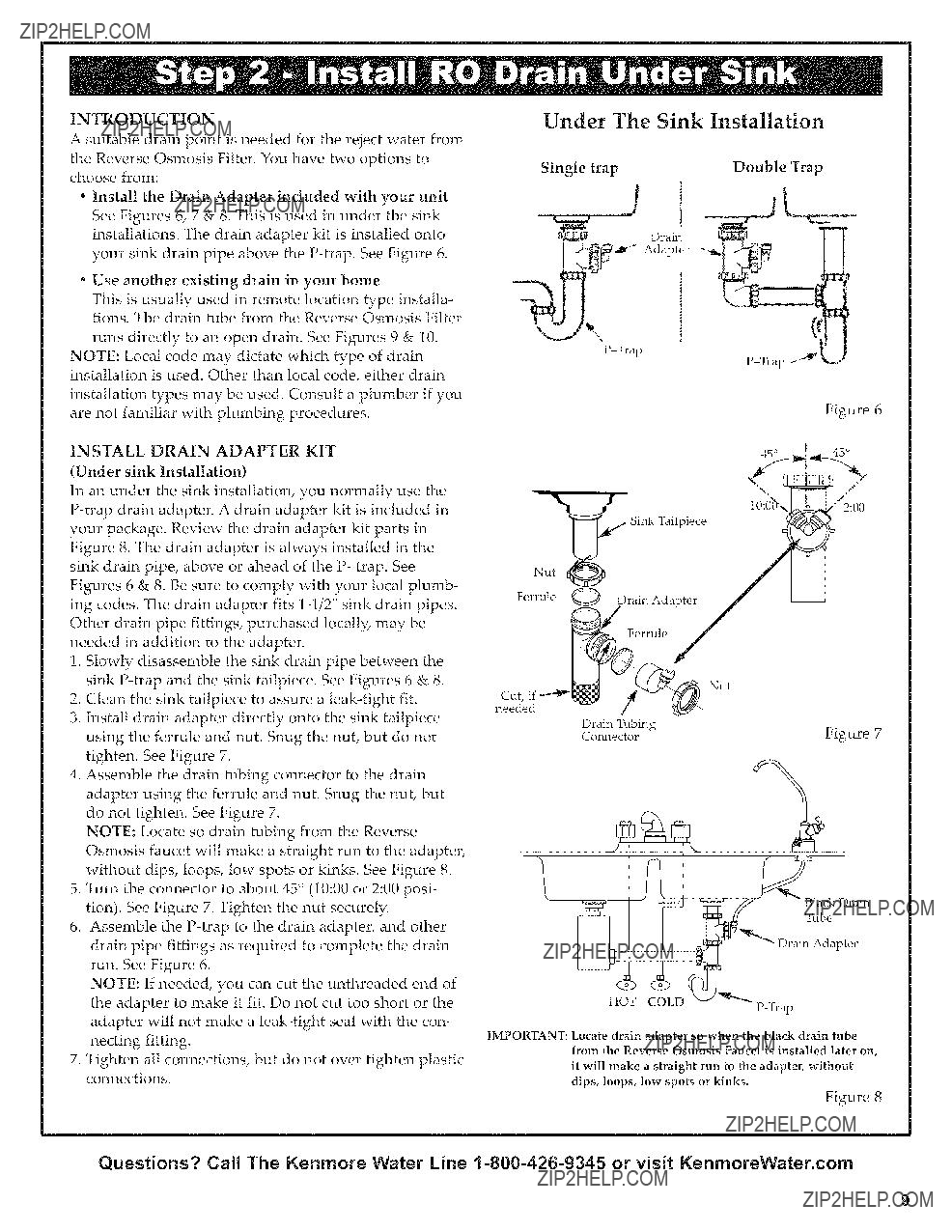
*Install the Drain Adapter included with your unit See Figures 6, 7 & 8. This is used in under the sink installations. The drain adapter kit is installed onto your sink drain pipe above the P-trap. See Figure 6.

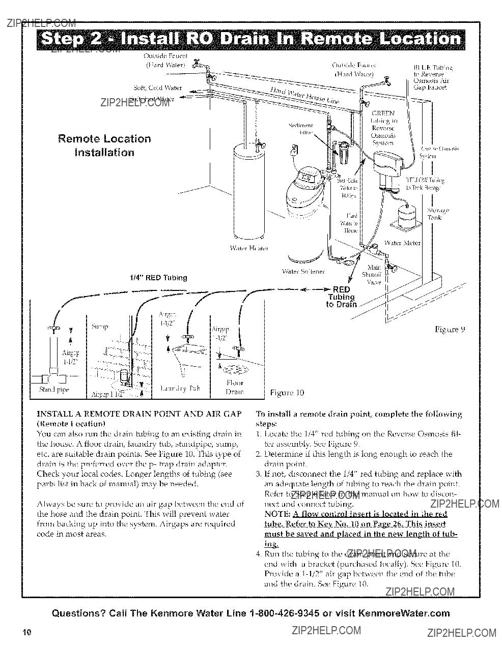
Use another existing drain in your home

This is usually used in remote location type installa- tions. The drain tube from the Reverse Osmosis Filter

runs directly to an open drain. See Figures 9 & 10. NOTE: Local code may dictate which type of drain installation is used. Other than local code, either drain installation types may be used. Consult a plumber if you are not familiar with plumbing procedures.

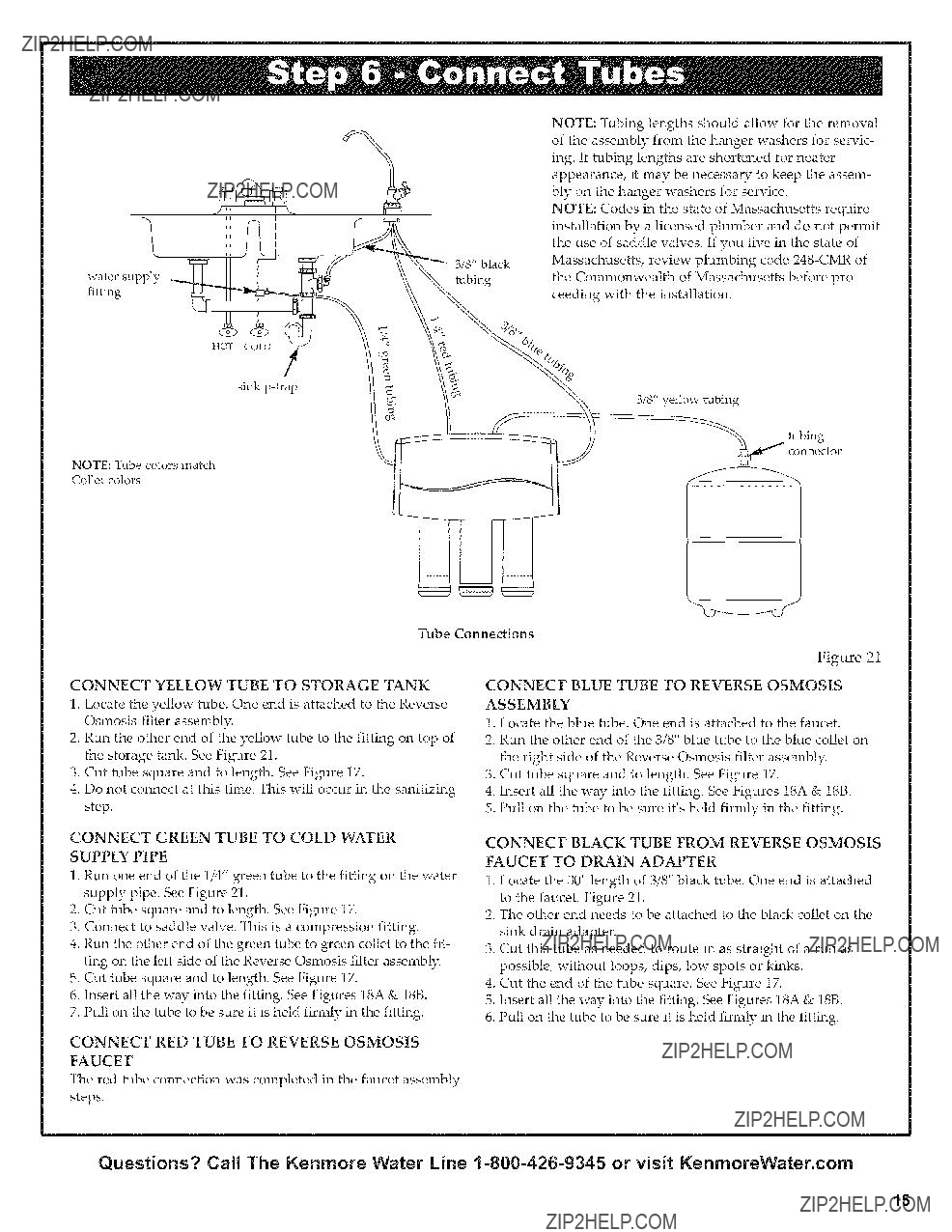
INSTALL DRAIN ADAPTER KIT (Under sink Installation)

in an under the sink installation, you normally use the P-trap drain adapter. A drain adapter kit is included in your package. Review the drain adapter kit parts in Figure 8. The drain adapter is always installed in the sink drain pipe, above or ahead of the P- trap. See Figures 6 & 8. Be sure to comply with your local plumb- ing codes. The drain adapter fits 1-1/2" sink drain pipes. Other drain pipe fittings, purchased locally, may be needed in addition to the adapter.

1.Slowly disassemble the sink drain pipe between the sink P-trap and the sink tailpiece. See Figures 6 & 8.

2.Clean the sink tailpiece to assure a leak-tight fit.

3.install drain adapter directly onto the sink tailpiece using the ferrule and nut. Snug the nut, but do not tighten. See Figure 7.

4.Assemble the drain tubing connector to the drain adapter using the ferrule and nut. Snug the nut, but do not tighten. See Figure 7.

NOTE: Locate so drain tubing from the Reverse Osmosis faucet will make a straight run to the adapter, without dips, loops, low spots or kinks. See Figure 8.

5.Turn the connector to about 45 ?? (10:00 or 2:00 posi- tion). See Figure 7. Tighten the nut securely.

6.Assemble the P-trap to the drain adapter, and other drain pipe fittings as required to complete the drain run. See Figure 6.

NOTE: If needed, you can cut the unthreaded end of the adapter to make it fit. Do not cut too short or the adapter will not make a leak-tight seal with the con- necting fitting.

7.Tighten all connections, but do not over tighten plastic connections.

Under The Sink Installation

Drain

_J Adapter

P-Trap

Figure 6

IMPORTANT: Locate drain adapter so when the black drain tube from the Reverse Osmosis Faucet is installed later on, it will make a straight run to the adapter, without

dips, loops, low spots or kinks.

Figure 8

Questions? Call The Kenmore Water Line 1-800-426-9345 or visit KenmoreWater.com

9

INSTALL A REMOTE DRAIN POINT AND AIR GAP

(Remote Location)

You can also run the drain tubing to an existing drain in the house. A floor drain, laundry tub, standpipe, sump, etc. are suitable drain points. See Figure 10. This type of drain is the preferred over the p- trap drain adapter. Check your local codes. Longer lengths of tubing (see parts list in back of manual) may be needed.

Always be sure to provide an air gap between the end of the hose and the drain point. This will prevent water

from backing up into the system. Airgaps are required code in most areas.

Figure 9

Figure 10

To install a remote drain point, complete the following steps:

1.Locate the 1/4" red tubing on the Reverse Osmosis fil- ter assembly. See Figure 9.

2.Determine if this length is long enough to reach the drain point.

3.if not, disconnect the 1/4" red tubing and replace with an adequate length of tubing to reach the drain point. Refer to Step 6 later in the manual on how to discon- nect and connect tubing.

NOTE: A flow control insert is located in the red tube, Refer to Key No. 10 on Page 26. This insert must be saved and placed in the new length of tub=

4.Run the tubing to the drain point and secure at the end with a bracket (purchased locally). See Figure 10. Provide a 1-1/2" air gap between the end of the tube and the drain. See Figure 10.

Questions? Call The Kenmore Water Line 1-800-426-9345 or visit KenmoreWater.com

10

INSTALL REVERSE OSMOSIS FILTER

ASSEMBLY

The Reverse Osmosis Filter Assembly is mounted on hanger washers. The hanger washers allow you to lift the filter assembly from the washers without any hardware removal. When planning your installation, you need to leave room for changing filters. See Figure 11.

Complete the following steps to install your Reverse Osmosis Filter Assembly:

1.Remove the cover.

2.Locate mounting slots on back of the assembly. See Figure 11.

3.Hold the assembly up to the wall surface and mark locations for the hanger washers. This allows room to change filters.

4.Fasten the hanger washers to the wall using the wood screws provided.

5.Hang assembly on washers.

6.Replace cover.

INSTALL STORAGE TANK

1.Apply thread sealing tape to the threads on the nipple at the top of the tank (max. 2 wraps). See Figure 12.

2.Locate the tubing connector. Tighten the tubing con- nector with a wrench onto the tank nipple 7-8 turns, being careful not to cross thread or overtighten. See Figure 12

3.Do not connect the tube at this time. This will occur later in the assembly.

4.Place the storage tank next to the Reverse Osmosis Assembly. The tank can be placed upright or on its side.

Hanger Washe_ (2) ::

Screw (2)

tank nipple

\

15-1/2" Minimum up from floor. This distance

allows for space to change filters

Figure 11

tank

Figure 12

Questions? Call The Kenmore Water Line i-800-426-9345 or visit KenmoreWater.com

li

SELECT LOCATION OF REVERSE OSMOSIS

FAUCET MOUNTING HOLE

You will need to select the location of the Reverse Osmosis Faucet. You have three options to choose from:

I

???Use the existing sink top hole for the spray hose or soap dispenser (Must be 1-1/4" in diameter)

Drill a new hole in the sink

Drill a new hole in the countertop next to the sink

. Determine where you are going to install your Reverse Osmosis Faucet.

2.Check to ensure the Reverse Osmosis faucet will mount flat against the mounting surface.

3.Visually review the routing of the tubes from the Reverse Osmosis filter assembly to the faucet. Check to ensure there is adequate tube routing space between the faucet and filter assembly.

4.if drilling is needed, drill a 1-1/4" diameter hole in the mounting surface.

IMPORTANT: Drilling holes into countertops and sinks should only be performed by a qualified installer who is certified for drilling such materials. Drilling of surfaces made of stone or solid surface materials such as granite, marble, Corian _Mor other plastic resin prod- ucts or sinks made of porcelain and stainless steel may cause permanent, irreparable damage to the sink or countertop surface.

INSTALL REVERSE OSMOSIS FAUCET

1.Locate and organize your RO faucet install parts. Refer to Figure 14.

2.Mount faucet base to sink hole until the faucet base is

square against the sink surface. The rubber gasket should be between the sink surface and the faucet

base.

3.Tighten the toggle bolts until the base is firmly mount- ed to the sink surface. Do not overtighten.

4.Locate the faucet base. The black and blue tubes are already connected to the faucet, insert these tubes into the sink hole until approximately one foot of tube length and the faucet base are left above the counter surface. Do not bend or kink the tubes in the process. See Figures 15 and 21.

black

red

Figure 13

Questions? Call The Kenmore Water Line 1-800-426-9345 or visit KenmoreWater.com

12

5.Locate the 1/4" red tubing. One end is connected to the

RO Filter assembly. See Figure 21. Locate the loose end.

A.Route red tube through countertop to faucet.

B.Cut the loose end of the red tube square and to length. See Figure 21.

NOTE: Tubing lengths should allow for the removal of the assembly from the hanger washers for servicing, if tubing lengths are shortened for nearer appearance, it

may be necessary to keep the assembly on the hanger washers for service.

C.insert all the way onto the 1/4" faucet barb fitting on faucet. See Figure 15.

D.Pull on the tubing to be sure it is held firmly in the

fitting.

NOTE: if you ran the red reverse osmosis drain tubing directly to a remote drain point, disregard step 3 and refer to instructions on page 10.

6. Mount the faucet body on to the faucet base, 1/4 turn.

FAUCET ELECTRONICS

inside the faucet base is a battery operated 6 month

timer. See Figure 14.

An amber LED indicator is also located in the front of

the faucet base. This LED will flash continuously after 6 months has passed. This indicates that it is time to replace the battery, prefilter and postfilter.

INSTALL BATTERY

To install battery, complete the following steps.

1.Loosen the screw on the right side of the faucet base. See Figure 14.

2.Press the battery housing upwards from the front faucet base until it releases from the faucet base. See

Figure 14.

3.Replace the battery (Maxell CR 2032 or equivalent). Place battery into the holder with the positive (+) side facing the back of the holder.

4.When the battery is first replaced it will flash six times and turn off. This indicates the battery is fully

charged. After the six flashes the timer enters the 6 month time cycle.

NOTE: if the LED repeatedly flashes just two times, it is not a fully charged battery and will need to be replaced.

5.Re-install the timer housing and firmly tighten the mounting screw. See Figure 14.

Figure 14

...... -J ......

BLACK TUBE

3/8" barb fitting for the black tube

UBE

BLUE

1/4" barb fitting 3/8" quick connectfor the red tube

fitting for the blue tube

Figure 15

Questions? Call The Kenmore Water Line 1-800-426-9345 or visit KenmoreWater.com

13

HOW TO CUT AND CONNECT THE TUBES

Your Reverse Osmosis Water System includes push-in

Foam Plug

Push In FittingN,. _

fittings for quick tubing connection. Review the follow- ing instructions before connecting the tubes in the next step.

Cut tubes to length

1.Use a sharp cutter or knife to cut the end of tubing. Always cut the tubing square. See Figure 17.

2.inspect the end (about 1") of the tubing to be sure there are no nicks, scratches or other rough spots, if needed, cut the tubing again. See Figure 17.

NOTE: Tubing lengths should allow for the removal of the assembly from the hanger washers for servicing, if tubing lengths are shortened for heater appearance, it

may be necessary to keep the assembly on the hanger washers for service.

Connect tubes

NOTE: Remove protective foam plugs before connect- ing tubes (See Fig. 16). Discard foam plugs.

1.Push tubing through collet, until it engages the o-ring. See Figure 18A. Continue pushing until the tube bot- toms out against the back of the fitting. See Figure 18B. A common mistake is to stop pushing when the tube engages the o-ring. This will lead to future leaks.

When a 1/4" tube is fully engaged, 11/16" of the tube has entered the fitting. When a 3/8" tube is fully engaged, 3/4" of the tube has entered the fitting. See Figures 18A & 18B.

2.if using tubing other than tubing supplied with the

system, be sure it is of high quality, exact size and roundness with a smooth surface.

To Disconnect Tubes

1.Push the collet inward with a finger tip. See Figure 20.

2.Continue holding collet inward while pulling the tub- ing out. See Figure 20.

\

Remove and Discard Foam Plugs

Figure 16

Push In Fitting

TubeNN_

Cut tubing square with end of tubing round, smooth, with no cuts, nicks or flat spots.

Tube Correctly Cut

Figure 17

O-Ring

/

Tube Partially Engaged With Fitting

Figure 18A

O-Ring

Tube Fully Engaged With Fitting

Questions? Call The Kenmore Water Line 1-800-426-9345 or visit KenmoreWater.com

14

cX9

i IOT COLD

/

sink p-trap

NOTE: Tubing lengths should allow for the removal of the assembly from the hanger washers for servic- ing. If tubing lengths are shortened for nearer appearance, it may be necessary to keep the assem- bly on the hanger washers for service.

NOTE: Codes in the state of Massachusetts require installation by a licensed plumber and do not permit the use of saddle valves. If you live in the state of Massachusetts, review plumbing code 248-CMR of the Commonwealth of Massachusetts before pro- ceeding with the installation.

3/8" yellow tubing

tubing

CONNECT RED TUBE TO REVERSE OSMOSIS

FAUCET

The red tube cormection was completed in the faucet assembly steps.

Questions? Call The Kenmore Water Line 1-800-426-9345 or visit KenmoreWater.com

15

SANITIZE THE SYSTEM

Sanitizing is recommended immediately after installation of the Reverse Osmosis system. It's also recommended after servicing inner parts. It is important that the person installing or servicing the system have clean hands while handling inner parts of the system.

Complete the following steps to sanitize the system. See Figure 22.

1.Turn off the water supply to the Reverse Osmosis sys- tem.

2.Open the Reverse Osmosis faucet, if the tank is not already empty, allow the water to empty:

3.Locate the eyedropper that is included in package and common household bleach (5.25%).

4.Add 3 ml. of bleach into open end of yellow tank tub- ing. Handle bleach according to bleach manufacturer's recommendations. See Figure 22.

5.Connect yellow tank tubing to tank connector. See Figures 12 and 22.

6.Sanitizing the system will be completed during the pressure test and purging steps on the following page. NOTE: The bleach must be removed from the system before drinking the water. See purging instructions on the next page.

//

1/

I/

I/

tl 11

II

I/

//

,7

//

Figure 22

Questions? Call The Kenmore Water Line 1-800-426-9345 or visit KenmoreWater.com

16

PRESSURE TEST THE SYSTEM

NOTE: Complete the sanitizing procedures on the pre- ceding page before pressure testing.

To pressure test the system, complete the following steps.

1.Turn the handle of the saddle valve counterclockwise to open the valve. See Fig. 23.

2.Open the water supply valve to the Reverse Osmosis System. See Figure 23.

3.Open the main water supply valve and several house faucets. This will purge air from the house plumbing and system. Close faucets when water runs smooth. See Figure 23.

NOTE: if leaking occurs at the saddle valve, you may need to tighten the saddle valve nut.

4.Pressure will start to build in the RO system in about 2 hours Carefully check all fittings and connections as the system builds pressure. Check for water leaks. Fix leaks if any are found, if problems exist, refer to the troubleshooting chart or call the toll free number.

NOTE: When the system is first pressurized, water may "spurt" from the faucet air gap hole until air is expelled from the RO system.

Please review the following operating features before using your Reverse Osmosis System:

You will not have filtered water immediately, it may

take 1-3 hours to completely fill the storage tank and create maximum flow from the Reverse Osmosis

faucet.

Water Pressure from the Reverse Osmosis faucet will be less than your standard faucet.

Water will run to the drain while the Reverse Osmosis system is producing water, even if you are not draw- ing water from the Reverse Osmosis faucet. You may hear a small quantity of water going to the drain for a couple of hours. Water going to the drain will auto- matically shut off when the storage tank is full.

PURGING THE SYSTEM

To purge the system, complete the following steps.

1.Open the Reverse Osmosis Faucet and let water

through the system for a 24 hour period.

NOTE: Water flow will be a slow trickle at this time.

2.Close the Reverse Osmosis faucet after the 24 hour purging period is complete.

3.When the purging is finished, your Reverse Osmosis system is ready for use.

Reverse"

Osmosis

Faucet

NOTE: Codes in the state of Massachusetts require installation by a licensed plumber and do not permit the use of saddle valves.

If you live in the state of Massachusetts, review plumb- ing code 248-CMR of the Commonwealth of Massachusetts before proceeding with the installation.

Questions? Call The Kenmore Water Line 1-800-426-9345 or visit KenmoreWater.com

17

HOW YOUR REVERSE OSMOSIS SYSTEM

WORKS

Introduction: Your Reverse Osmosis (RO) Drinking Water System uses your household water pressure to force water through three filters. Minerals and impurities are filtered out. Delicious tasting drinking water goes to the storage tank-ready for your use. Minerals and impu- rities are sent down the drain. The following paragraphs will explain in detail how your Reverse Osmosis

Drinking Water System works.

Prefilter: Water from the cold supply pipe enters the pre- filter. See Figure 24. The prefilter has a replaceable sedi- ment cartridge with activated carbon in its composition. The cartridge reduces taste, odor, sand, silt, dirt, other sediments, and up to the amount of chlorine shown in the specifications.

Reverse Osmosis Cartridge: Filtered water flows from the prefilter, to the Reverse Osmosis membrane car- tridge. See Figure 24. The Reverse Osmosis cartridge is a tightly wound special membrane. The membrane

reduces the dissolved solids and organic matter. High quality product water (about one ounce per minute) exits the Reverse Osmosis cartridge. The product water flows to the storage tank, postfilter or Reverse Osmosis faucet. See Figure 24. Reject water, with the dissolved solids and organic matter, is routed to the drain. See Figure 24.

Storage Tank: The storage tank holds product water. See Figure 24. A diaphragm inside the tank holds water pres-

surized to about 30 psi when the tank is full. This pro- vides fast flow to the Reverse Osmosis faucet. When the

tank is empty of water, it is pressurized to 5 - 7 psi.

Postfilter: Before going to the Reverse Osmosis faucet, product water goes through the postfilter. See Figure 24. The postfilter is an activated carbon type filter. Any remaining tastes and odors are reduced from the prod- uct water. Clean, high quality drinking water is available at the faucet.

Reverse Osmosis Faucet: The sink or countertop faucet has a hand operated knob to access drinking water. See Figure 24. An air-gap is built into the faucet drain water

connection to comply with plumbing codes. See Figure 24.

Faucet Electronics: Inside the faucet base is a battery

operated 6 month timer. See Figure 14. An amber LED indicator is also located in the front of the faucet base.

This LED will flash continuously after 6 months have passed. This indicates that it is time to replace the bat- tery, prefilter and postfilter.

Shutoff Assembly: The unit has an automatic shutoff system to conserve water. When the storage tank has filled to capacity, and the drinking water faucet is closed, pressure closes the shutoff to stop flow to the drain.

After enough drinking water is used, pressure in the sys- tem drops, and the shutoff opens to allow the tank to be refilled. See Figure 24.

Check Valve: A check valve is located in the Reverse

Osmosis manifold, above the center sump. The check valve prevents a backward flow of product water from the storage tank to drain. A backward flow could dam- age the Reverse Osmosis Membrane. See Figure 24.

Flow Control: Water flow to the drain is restricted by the flow control, it maintains the desired flow rate to obtain

the highest quality drinking water. The flow control is located in the end of the 1/4" red drain tubing, at the Reverse Osmosis manifold drain port. See Figure 24.

Questions? Call The Kenmore Water Line 1-800-426-9345 or visit KenmoreWater.com

18

PRODUCT

WATER FAUCET

air

@

PRODUCT WATER

gravity drain

WASTE WATER

AUTOMATIC drain flow check

SHUTOFF control valve

WATER

IN

GREEN

PREFILTER

o_

i POSTFILTER

IL

D

D

Reverse Osmosis Water Flow Schematic

Figure 24

Water Flow Description

1.Water enters prefilter. Sand, silt and other sediments are reduced. Chlorine is also reduced.

2.Water leaves prefilter and proceeds to the Reverse Osmosis Cartridge.

3.Water enters the Reverse Osmosis membrane. Dissolved solids are reduced.

4.Processed water leaves the Reverse Osmosis Membrane and flows to the storage tank.

5.Waste water with dissolved solids leave the Reverse Osmosis membrane and flows to the drain.

6.Faucet is activated.

7.Processed water leaves the storage tank and flows to the post filter filtered to ensure fresh taste.

8.Water flows to the Reverse Osmosis faucet.

Questions? Call The Kenmore Water Line 1-800-426-9345 or visit KenmoreWater.com

19

PREFILTER/POSTFILTER MAINTENANCE

NOTE: It is recommended to replace the battery, prefilter and postfilter cartridges at least every 6 months of prod-

uct water use. Replace more often if they begin to plug with sediments.

The prefilter and postfilter are replaceable sediment car- tridges with activated carbon in its composition. See Figure 25. You must periodically replace the prefilter and postfilter cartridge. This will protect the RO membrane from being destroyed by chlorine. It will also prevent the filters from plugging with sediments.

You may notice a slower output of product water as the prefilter and postfilter build up with sediments. Replace the prefilter and postfilter cartridges when this occurs.

You should replace the battery whenever you replace the cartridges.

RO MEMBRANE CARTRIDGE MAINTENANCE

The Reverse Osmosis cartridge is a tightly wound special membrane. See Figure 25. The membrane reduces the dissolved solids and organic matter. The life of the

Reverse Osmosis membrane cartridge depends mostly on the pH and hardness of the supply water. (see specifi- cations). Cartridge life is shorter with higher pH. For example, if supply water pH is from 6.8 to 7.7, the car- tridge may last for well over one year. However, car- tridge life may be as short as 6 months if the pH is as high as 8.5 to 10. Higher pH weakens the cartridge mem- brane and causes pin-hole leaks, it's time to replace the Reverse Osmosis cartridge when the production rate and/or quality of product water drops. Product water may begin to taste different or bad, indicating solids and organics are passing through the Reverse Osmosis mem- brane. See Reverse Osmosis cartridge replacement.

REVERSE OSMOSIS CARTRIDGE REPLACEMENT Complete the following steps to replace the cartridges.

1.If possible, turn off the water supply to the RO system.

2.Remove (turn to the left) the pre filter cartridge from the filter head to relieve pressure on the Reverse Osmosis cartridge.

3.Remove the Reverse Osmosis cartridge.

4.Remove the postfilter cartridge.

5.Discard the cartridges in a proper manner.

6.install new cartridges in reverse order (postfilter, Reverse Osmosis and then prefilter). Turn cartridges to the right to re-attach to the filter heads.

7.Remove and replace the timer battery. See Figure 14.

8.Turn on the water supply to the RO system.

9.Purge the Reverse Osmosis membrane cartridge. See page 17 for instructions.

Cover

Prefilter

Cartridge

Postfilter

Cartridge

Complete the following steps to replace the cartridges.

1.If possible, turn off the water supply to the RO system.

2.Remove the pre filter cartridge (turn to the left) from the filter head. Then remove the post filter cartridge.

3.Discard the cartridges in a proper manner.

4.install new cartridges in reverse order (postfilter first, then pre filter). Turn cartridges to the right to re-attach to the filter heads.

5.Remove and replace the timer battery. See Figure 14.

6.Turn on the water supply to the RO system.

7.Purge the Reverse Osmosis membrane cartridge. See page 17 for instructions.

Questions? Call The Kenmore Water Line 1-800-426-9345 or visit KenmoreWater.com

2O

FLOW CONTROL

The flow control is vital for proper operation of the Reverse Osmosis membrane cartridge. See Figure 26. The flow control, located in the red tube at the system hous- ing, keeps water flowing through the membrane at the required rate. This is to ensure the system produces the best quality product water.

Periodically check the flow control assembly to be sure the small hole through it is clean and unrestricted.

if the flow control assembly requires service, review the exploded view in Figure 26. Assemble and disassemble as shown.

CHANGE COLLET AND O-RING

1.Remove the collet and o-ring from the fitting with a small screwdriver. Be careful not to scratch the inter-

nal walls of the collet port. See Figures 27 & 28.

2.Clean collet port, lubricate and insert the o-ring seal into the bottom of the port. See Figures 27 & 28.

3.Push the collet inward until it locks in place. See Figures 27 & 28.

CHANGE BATTERY

To change battery, complete the following steps.

1.Loosen the screw on the right side of the faucet base. See Figure 29.

2.Press the battery housing upwards from the front faucet base until it releases from the faucet base. See

Figure 29.

3.Replace the battery (Maxell CR 2032 or equivalent). Place battery into the holder with the positive (+) side facing the back of the holder.

4.When the battery is first replaced it will flash six times and turn off. This indicates the battery is fully

charged. After the six flashes the timer enters the 6 month time cycle, if it repeatedly flashes just two times, it is not a fully charged battery:

5.Re-install the battery housing and firmly tighten the mounting screw. See Figure 29.

i (...].

Flow Control Insert

.....ifz

i_...._ 1/4" Red Tubing

Drain

Figure 26

Push o-ring seal into bottom of port then follow with collet.

Fitting

O-Ring Seal

Collet

Change collet and o-ring

Figure 27

Collet (depress to remove tubing)

Disconnect Tubing

Figure 28

Battery

Bartery

negative(-)_.__

Figure 29

Questions? Call The Kenmore Water Line 1-800-426-9345 or visit KenmoreWater.com

21

This system conforms to NSF/ANSI 58 for the specific performance claims as verified and substantiated by test data.

_@Feed water supply at 50 psi, 77??E and 750 TDS. Quality water production, amount of waste water and percent rejection all vary with changes in pressure, temperature and total dissolved solids.

2Efficiency rating means the percentage osmosis treated water under operating

of the influent water to the system that is available to the user as reverse conditions that approximate typical daily usage.

3Recovery rating means the percentage of the influent water to the membrane portion of the system that is available to the user as reverse osmosis treated water when the system is operated without a storage tank or when the storage tank is bypassed.

Non-potable Water Sources: Do not attempt to use this product to make safe drinking water from non-potable water sources. Do not use the system on microbiologically unsafe water, or water of unknown quality without an adequate disinfection before or after the system. This system is certified for cyst reduction and may be used on disinfected water that may contain filterable cysts.

Arsenic Reduction: This system shall only be used for arsenic reduction on chlorinated water supplies containing detectable residual free chlorine at the system inlet. Water systems using an inline chlorinator should provide a one minute chlorine contact time before the reverse osmosis system.

Nitrate/Nitrite Test Kit: This system is acceptable for treatment of influent concentrations of no more than 27mg/L nitrate and 3mg/L nitrite in combination measured as N. It is certified for nitrate/nitrite reduction only for water sup- plies with a pressure of 280 kPa (40 psig) or greater. This system is supplied with a nitrate/nitrite test kit. Product water should be monitored periodically according to the instructions provided with the test kit.

TDS Test Kits: TDS test kits are available by calling 1--800--949--8220, or check the water testing section of your local phone directory:

Installations In The Commonwealth Of Massachusetts: The Commonwealth of Massachusetts requires installation be performed by a licensed plumber and do not permit the use of saddle valves. Plumbing code 248--CMR of the Commonwealth of Massachusetts must be followed in these cases.

Product Water Testing: The Reverse Osmosis System contains a replaceable treatment component critical for the effective reduction of total dissolved solids. Product water should be tested periodically to verify that the system is performing properly:

Questions? Call The Kenmore Water Line 1-800-426-9345 or visit KenmoreWater.com

22

Questions? Call The Kenrnore Water Line 1=800=426=9345 or visit KenrnoreWater.corn

23

iiii!ii iii i iiiiiii!!ii i iilii ii!:: ii iii! ii iiiiiii i i ii!!iiiii iiii!iiii iiiii i iliiiiil!i!i !i!i!i !i

Cause: Reverse Osmosis membrane cartridge expended.

Cause: Contamination in product water storage Correction: tank.

Cause: Water supply to the Reverse Osmosis sys- Correction: tem not within specifications.

Replace the post filter cartridge. If taste and odor persists, replace the prefilter cartridge and Reverse Osmosis membrane cartridge.

See page 20.

Use sanitizing procedures. Replace pre and post filter cartridge. See pages "16& 20.

Sanitize entire system. Call 1-800-426-9345 for instructions.

Increase water pressure, precondition the water, etc., as needed to conform before doing maintenance on the Reverse Osmosis system.

Cause: Prefitter or Reverse Osmosis mem-

brane cartridges plugged with sedi- ments.

Cause: Storage tank air-charge bessthan 5-7 psi.

Correction: Replace the prefilter cartridge. If rate does not increase, replace the postfilter cartridge and Reverse Osmosis membrane cartridge. See page 20.

_te th:_

Correction: Open Reverse Osmosis faucet and drain tank until flow slows to a drip. Keep faucet open and check tank pressure. If low, pressur- ize to 6 psi. Close faucet to refill the tank.

Correction: Send treated and untreated water samples to a water analysis lab for testing. It is important to test both the treated and untreated water to determine system performance. If the TDS is not within the system's performance guidelines, replace the prefitter, post fit- ter and RO membrane cartridges.

Cause: Missing flow control insert in red drain tube [Correction: or its corresponding port.

Replace flow control insert. See page 21.

Questions? Call The Kenmore Water Line 1-800-426-9345 or visit KenmoreWater.com

24

Cause: Outer tubing surface finish not smooth. Correction: Remove tube from connection. Remove problem area by cutting tube to shorter length. Re-insert in connection. See page "14.

Questions? Call The Kenmore Water Line 1=800=426=9345 or visit KenmoreWater.com

25

o-r_ng seal

6J _ ??

collet

_) //17

20

- . ---. ....

I

11

I .16

J

Questions? Call The Kenmore Water Line 1-800-426-9345 or visit KenmoreWater.com

26

107275185Flow (Control) Insert

113805605Pre & Post Filter Cartridge

123857705RO Membrane Cartridge +

207281013Push=in Fitting Kit, 3/8" ??? o

217285368Repl. Manifold Assembly (incl. Key Nos. 3 - 9, 19 & 20)

Please purchase replacement pre & post filter cartridges from the retail store where you bought your reverse osmosis system.

+Please call 1-800-4-MY-HOME (1-800-469-4663) to purchase replacement RO membrane cartridges.

These o-rings and collets are for replacement in the manifold housing only. They do not fit the other push-in fitting on Key No. 16.

o Not included.

Tubing lengths for remote installations, direct replacement for colored lengths of tubing.

[] Not illustrated.

Questions? Call The Kenmore Water Line 1-800-426-9345 or visit KenmoreWater.com

27

iiiiiiiiiiiiiiiiiiiiiiiiiiiiii!...._

iiiiiiiiiiiiiiiiiiii iiiiiiiiiiiiiiiiiiii iiiiiiiiiiiiiiiiiiii iiiiiiiiiiiiiiiiiiii

iiiiiiiiiiiiiiiiiiii iiiiiiiiiiiiiiiiiiii

Your Home

For expert troubleshooting and home solutions advice:

www.managemyhome.com

iiiiiiiiiiiiiiiiiiiiFor repair - in your home - of all major brand appliances, iiiiiiiiiiiiiiiiiiiilawn and garden equipment, or heating and cooling systems,

iiiiiiiiiiiiiiiiiiii no matter who made it, no matter who sold it!

iiiiiiiiiiiiiiiiiiii For the replacement parts, accessories and iiiiiiiiiiiiiiiiiiii owner's manuals that you need to do-it-yourself.

iiiiiiiiiiiiiiiiiiii

iiiiiiiiiiiiiiiiiiii For Sears professional installation of home appliances iiiiiiiiiiiiiiiiiiii and items like garage door openers and water heaters.

??Registered Trademark / TMTrademark / SMService Mark of Sears Brands, LLC

??Marca Registrada / TMMarca de F_brica / SM Marca de Servicio de Sears Brands, LLC