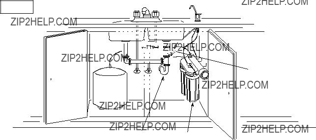
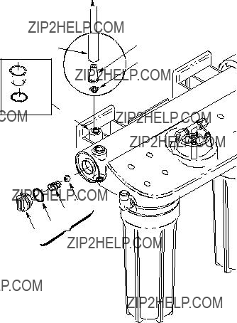
2.Press inward while turning the RO cap to the left (?) to remove from the bracket/membrane housing.
3.Use a pliers, or heavy wire made into a hook, to pull the RO cartridge from the housing.
Note: Sanitizing is recommended after servicing in- ner parts of the system (see page 9).
4.Install the new cartridge, end with o- ring seals in- ward. Work back and forth to get all the way in (end of cartridge about 1-1/4??? in from end of housing).
5.Lubricate the RO cap o- ring seal if dry. Replace the o- ring into the cap. Press inward on the cap while turning to the right (?)to lock. The cap will not go on if the RO cartridge is not fully seated inward.
6.Check the flow control and screen (see below).
7.Purge the RO membrane cartridge following instruc- tions on page 9.
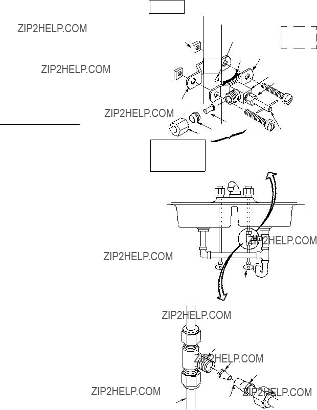
FLOW CONTROL AND SCREEN
The flow control is vital for proper operation of the RO membrane cartridge. The control keeps water flow through the membrane at the needed rate to ob- tain the best quality product water.
Whenever servicing the RO system, check the flow control to be sure the small hole through it is clean and unrestricted. Also check and clean or replace the cone- shaped screen in front of the control. The RO membrane cannot discharge minerals and impuri- ties to the drain if the flow control plugs with foreign material. If this happens, it only takes a short time for the membrane to foul and become useless.
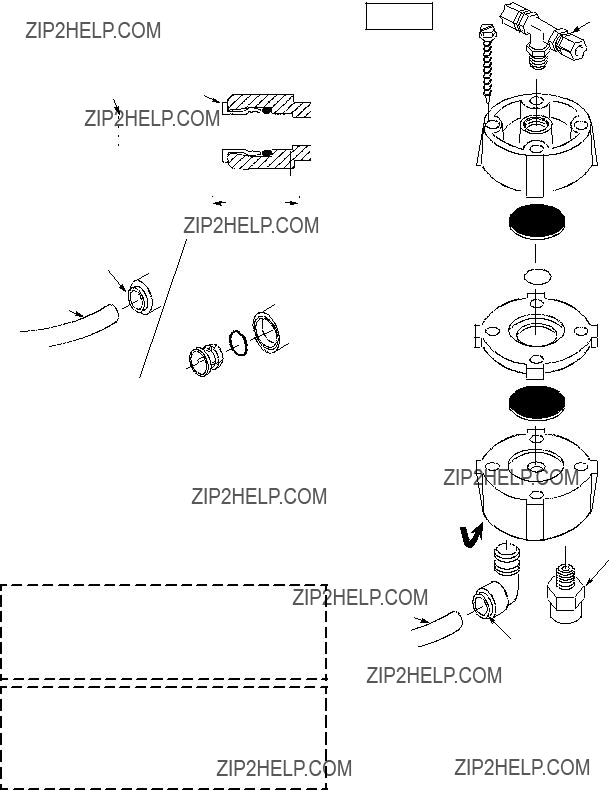
To clean/replace flow control and screen (FIG. 10):
1.At the drain connection, depress the collet (FIG. 11) with a finger while carefully pulling on the drain tubing to remove.
2.Remove the flow control from the end of the drain tubing. Be sure the center hole is clean.
3.Check the drain tubing to be sure it???s clean. Then, insert the cleaned or new flow control into the tubing.
4.With a small screwdriver, carefully remove the col- let and o-ring from the drain port. Use a small need- le-nose pliers or tweezers to remove the screen from the drain port. Thoroughly clean, or replace with a new screen. Install, pointed end down.
Note: Visually check to be sure it is positioned cor- rectly.
5.Inspect the o-ring and collet. Replace if worn, cut or otherwise damaged. Carefully replace into the drain port.
6.Be sure the flow control is in the end of the tubing, then push all the way into the fitting.
flow (control) insert
1/4???tubing
screen
 collet
o--ring seal
drain port
ball
spring  o-ring
cap  check
check
valve
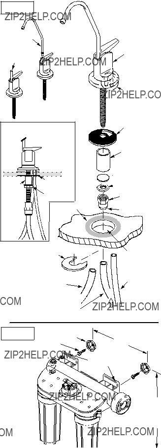
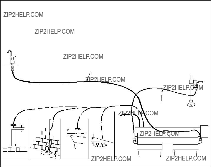
TUBING CONNECTION
(all push- in fitting locations)
This RO system includes push- in fittings for quick tubing connection at most locations. If working with the fittings, do the following.
Connection (FIG. 11):
1.Use a sharp cutter or knife to cut the end of tubing square.
2.Inspect the end (about 1???) of the tubing to be sure there are no nicks, scratches or other rough spots. If needed, cut the tubing again.
3.Push tubing through the collet and all the way into fitting. Full engagement is 11/16??? for 1/4??? tubing, and 3/4??? for 3/8??? tubing.
continued


 supply


 washer
 hex nut


 1/8???NPT x 1/4???Tube Male Elbow,1/8???


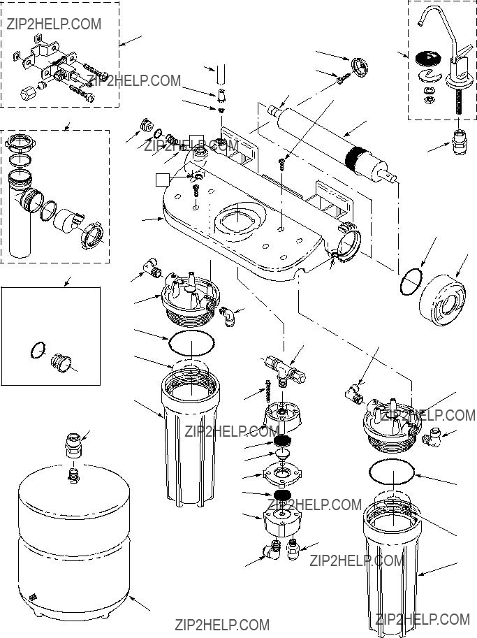


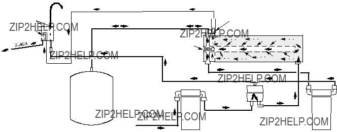
 airgap
  airgap