OWNER'S
MANUAL
MODEL NO.
UltraFilter 150
625.385700
UltraFilter 350
625.385720
Caution:
Read and Follow
All Safety Rules and
Operating Instructions
Before First Use of
This Product.
If you have questions when installing, operating or maintaining your reverse osmosis system, call this
For repair or replacement parts, call this
See back cover for other Sears service numbers.
www.KenmoreWater.com
SAVE THIS MANUAL
Reverse Osmosis
Drinking Water System
_i, Warranty
_i, How To Install
_i, How It Works
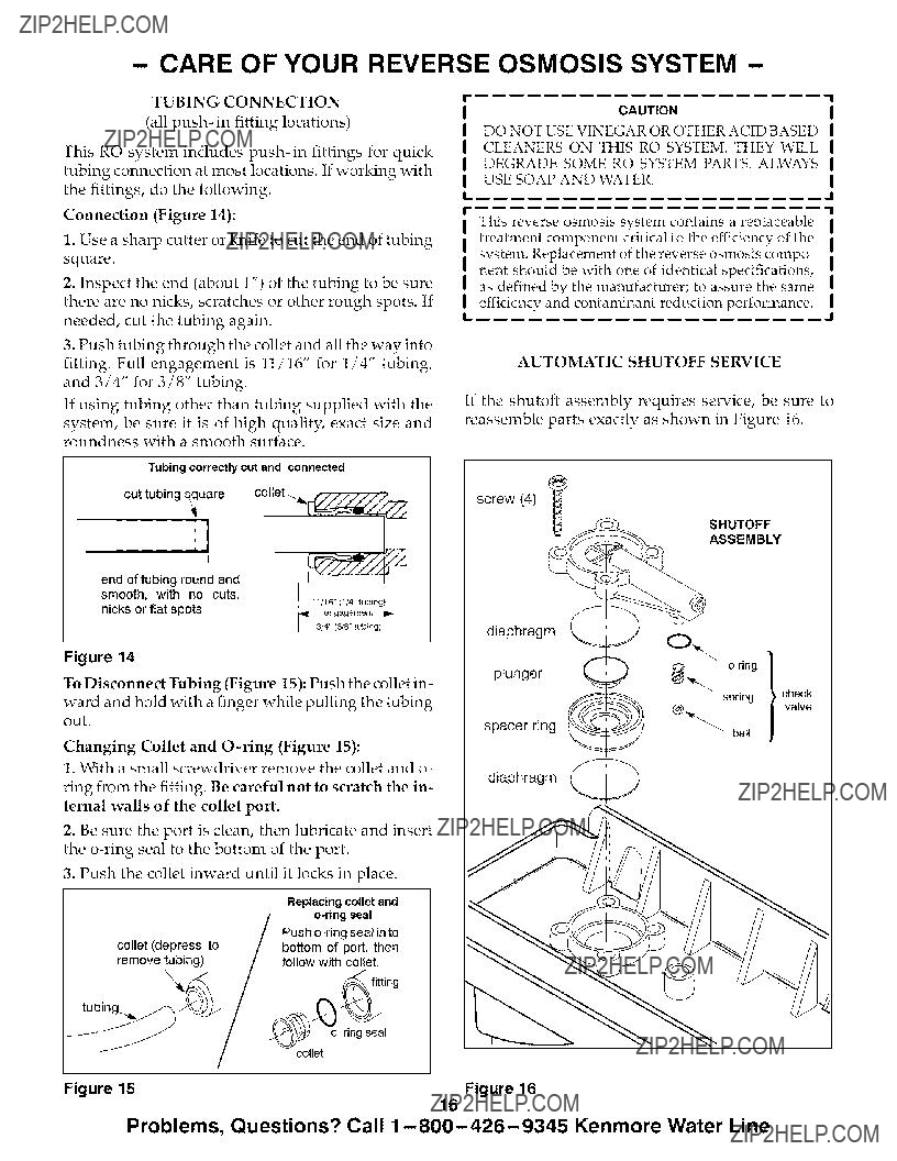
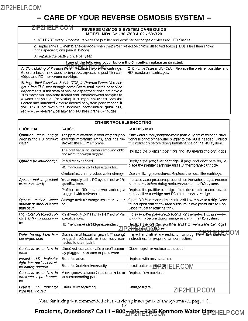
_i, Care Of
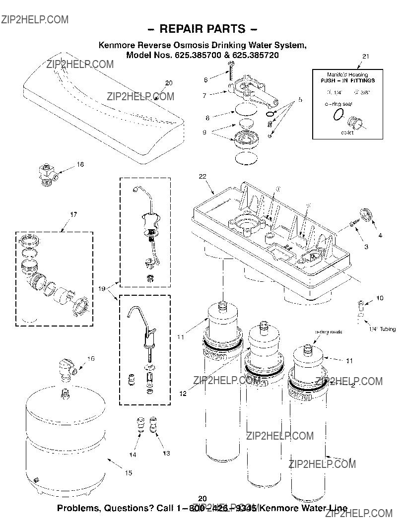
_i, Repair Parts
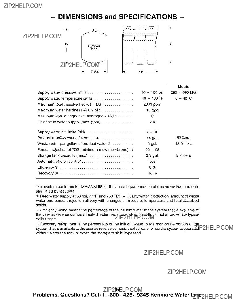
System tested and certified by NSF International to NSF!ANSl Standard 58 for the reduction of the
claims specified on the performance data sheet.
Sears, Roebuck and Co., Hoffman Estates, IL 60179 U. S. A.