INSTALLATION CO.VEBLRGET,ASGRILL JENN-AIR

MANUAL JGD8130& JGD8345

COOKTOPSERIES

DIMENSIONSSHOWNIN BOTHINCHESAND CENTIMETERS

*Blowermayberotatedforhorizontalorverticaldirectionbylooseningnutsaroundblowerinlet.Accessibleinsideventilation chamber.

???NOTICETO INSTALLER:Leavetheseinstructionswiththe appliance.

???NOTICETO CONSUMER:Retaintheseinstructionsf rfuturereference.

??? Dimension"A"- Provide2" rain.(5.08cm)cabinetclearanceto motorforcoolingpurpose.

??? Note- Wherepossible6," (15.24cm)isrecommendefdormotor/bloweservice.

??? SideClearance- Grillsinstalledneara sidewallmustallowa minimumclearanceof 8".

??? Accessmustbeprovidedto removeandemptygreasecontainer(s).

INSTRUCTIONSTOINSTALLER 8101 P406..60

(09-01-00)

L

InstallingCabinetryOverYourJenn.AirGrill

*A = 30" (76.2 ??m) minimum vertical clearance between cooking surfaceand construction above the appliance.

*B = 13" (33.02 cm) maximum depth of cabinets installed above cooking top.

of local codes, with the latest edition of the National Electrical Code ANSI/NFPA No. 70 USA or currant CSA STANDARD C22.1 Canadian Electrical Code part 1.

IDottedlines

indicate

'rangehood

iconstruction

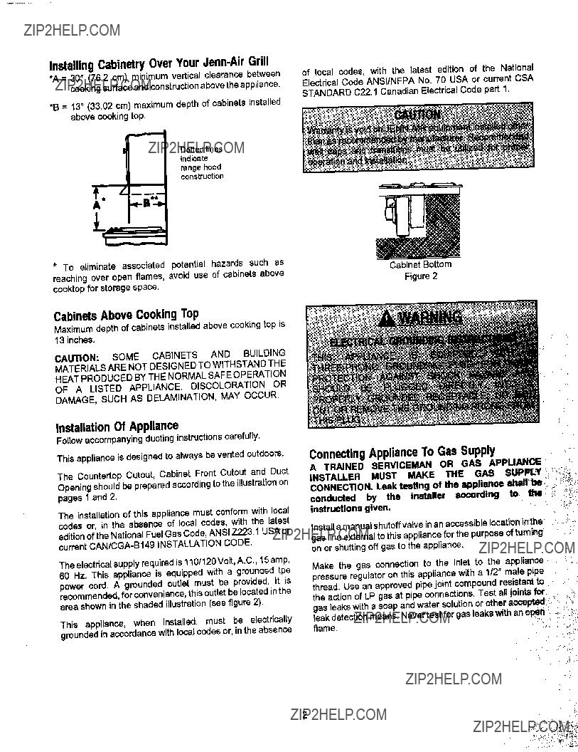
CabinetsAboveCookingTop

Maximum depth of cabinets installed above cooking top is 13 inches.

CAUTION: SOME CABINETS AND BUILDING

MATERIALS ARE NOT DESIGNED TO WITHSTAND THE

HEAT PRODUCED BY THE NORMAL SAFE OPERATION

OF A LISTED APPLIANCE. DISCOLORATION OR

DAMAGE, SUCH AS DELAMINATION, MAY OCCUR.

InstallationOf Appliance

Followaccompanyingducting instructionscarefully.

This appliance is designed to always be vented outdoors. The Countertop Cutout, Cabinet Front Cutout and Duct

Opening shouldbe prepared accordingto the illustrationon pages 1 and 2.

The installationof this appliancemust conform with local codes or, in the absence of local codes, with the latest

editionof the National FuelGas Code, ANSI Z223.1 USA or currentCAN/CGA-B149 )NSTALLATION CODE.

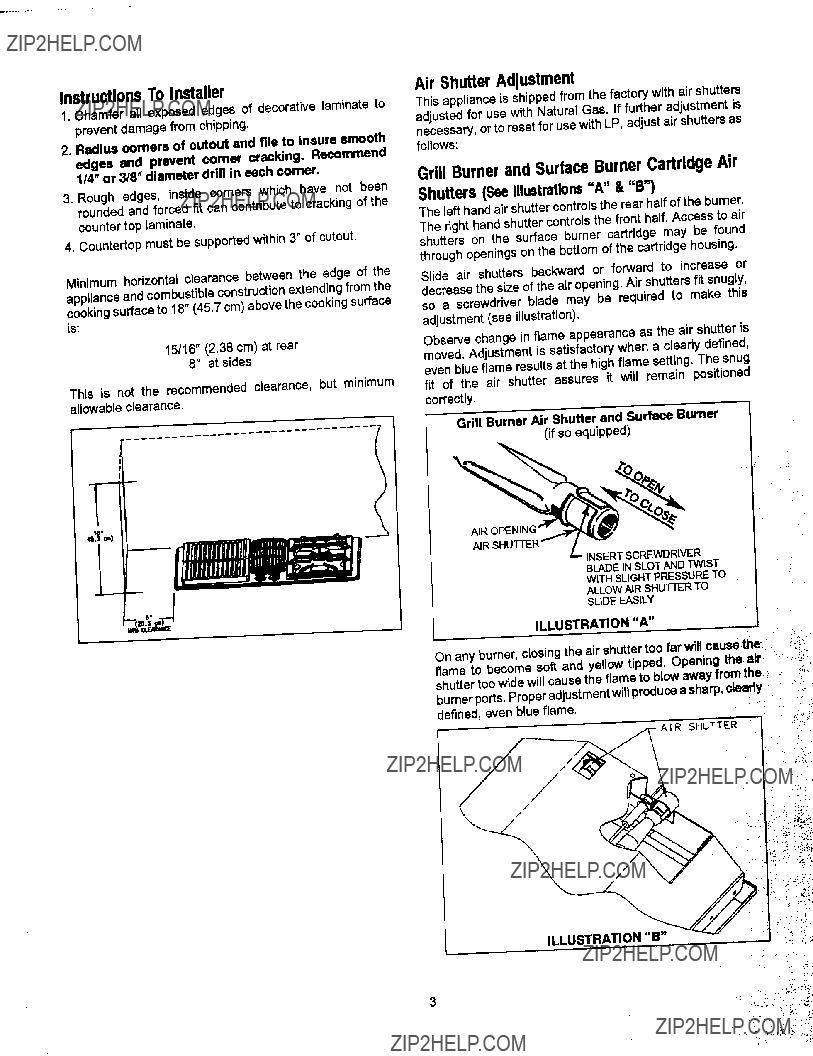
The electricalsupplyrequiredis 110/120 Volt,A.C., 15 amp, 60 Hz. This appliance is equipped with a grounded tpe power cord. A grounded outlet must be provided. It is recommended, for convenience, this outlet be located inthe area shown in the shaded illustration (see figure 2).

This appliance, when installed, must be electrically groundedin accordance with local codes or, in the absence

ConnectingApplianceToGasSupply

A TRAINED SERVICEMAN OR GAS APPLIANCE

conducted by the installer according to the _ -7 instructions given.

Installa manualshutoffvalve inan accessiblelocationinthe gas lineexternalto this appliancefor the purposeof turning on or shuttingoffgas to the appliance.

Make the gas connection to the inlet to the appliance pressure regulator on this appliance with a 1/2" male p_pe

thread. Use an approved pipe joint compound resistant to

the action of LP gas at pipe connections. Test all joints for gas leaks with a soap and water solution or other accepted

leak detection means. Never test for gas leakswith an opeIT" .. :: flame....

InstructionsToInstaller

1.Chamfer all exposed edges of decorative laminate to prevent damage from chipping,

2. Radius corners of outout and file to insure smooth edges and prevent corner cracking. Recommend

1/4" or 3/8" diameter drill in each corner,

3. Rough edges, inside comers which have not been rounded and forced fit can contribute to cracking of the counter top laminate.

4, Countertopmust be supportedw(thin 3" of cutout.

Minimum horizontal clearance between the edge of the

appliance and combustible construction extending from the cooking surface to 18" (45.7 cm)above the cooking surface is:

15/16" (2.38 cm) at rear

8" at sides

This is not the recommended clearance, but minimum allowable clearance,

j'"-

.............................t

So J

AirShutterAdjustment

This appliance is shipped from the factory with air shutters adjusted for use with Natural Gas. If further adjustment is necessary,or to reset for use with LP, adjustair shutters as follows:

Grill BurnerandSurfaceBurnerCartridgeAir

Shutters(SeeIllustrations"A" & "B')

The left handair shuttercontrolsthe rear halfof the burner,

The right hand shutter controlsthe front half. Access to air shutters on the surface burner cartridge may be found

throughopenings on the bottom of the certridge housing.

Slide air shutters backward or forward to increase or

decrease the size of the air opening. Air shutters fit snugly, so a screwdriver blade may be required to make this adjustment (see illustration).

Observe change in flame appearance as the air shutter is moved. Adjustment is satisfactory when a cleady defined, even blue flame results at the high flame setting. The snug fit of the air shutter assures it will remain positioned correctly.

(if SOequipped)

,.o

Grill Burner Air Shutter and Surface Burner

ILLUSTRATION _ _'_-"//

LowFlameAdjustment(SeeIllustration"C")

This appliance is shipped from the factory with low and medium flame settings adjusted for use with Natural Gas. If further adjustment is necessary, or to readjust for use with LP, proceed as follows:

1.Light burner and set control knob for low flame.

2.Remove control knob from valve stem.

3.Insert a slender, thin-blade screwdriver into the recess at

center of valve stem and engage blade with slot in adjusting screw.

4. Turn center stem adjusting screw to set flame size.

???clockwise to reduce.

???counterclockwise to increase.

5.Replace control knob when adjustment is completed.

Proper adjustment will produce a stable, steady blue flame of minimumsize. The final adjustment should be checked by

turning knob from high to low several times without extinguishing the flame.

This adjustment, at low setting, will automatically providethe proper flame size at medium setting.

INCREASE FLAME SIZE

CLOCKWISE

TO REDUCE

FLAME SIZE

COUNTERCLOCKWISE TO

VA'"___,-._,,,_i_._-

ILLUSTRATION "C"

PressureTesting

The maximum gas supply pressure for the appliance pressure regulator supplied on this appliance is 14" W.C. The test pressure for checking this appliance pressure regulator must be at least 6" W.C. for Natural Gas, and at least 11" W.C. for LP. It is shipped from the factory set for Natural Gas at 5" W.C. output pressure.

This appliance and its individual shutoff valve must be

disconnected from the gas supply piping system during any pressure testing of that system at test pressures in excess of 1/2" PSIG (3.5 k Pa).

This appliance must be isolated from the gas supply piping system by closing its individual manual shutoff valve during any pressuretesting of the gas supply piping system at test pressures equal to or less than 112"PSIG (3.5 k Pa).

AppliancePressureRegulatorConversion

(See Illustration "D")

This unit is supplied with a Maxitrol Appliance Pressure Regulator. Follow the instructions in illustration "D".

MAXITROL APPLIANCE PRESSURE REGULATOR

ILLUSTRATION "D"

ConversionToLPGas

5

TOCONVERTAPPLIANCEFORUSEWITHPROPANEGAS

NaturalGasTo PropaneGas(LP)ConversionInstructions

JGD8345(Shown)

6

TOCONVERTAPPLIANCEFORUSEWITHNATURALGAS

PropaneGas(LP)ToNaturalGas

ConversionInstructions

If this appliance has been convertedfor use with LP Gas,

each of the followingmodificationsmustbe performedto convertthe unit back to NaturalGas.

Models- JGD8130& JGD8345Series

Manifold - NaturalGas pressurerequired- 5" W.C,

Incoming Natural Gas pressure required to appliance pressureregulator- 6" - 7" W.C.

Natural Gas input specified,Model JGD8130/JGD8345 - 36,000 BTU/hr / 56,000 BTU/hr.

A.Replaceallorificehoods- Perform steps1 through4on page4. Locatethe (4) fouror (2) twoNaturalGas hoods (with small numbers stamped on their sides) saved from the originalNatural Gas unit. Page 4 Illustration "E". The two hoodswith .0520 (#55 orifice)stamped on themare for the left frontand left rear burners.The two hoodswiththe .0550 (#54 orifice)stampedon themare for the two rightburners.

To make these conversion adjustments follow the

inatructions and illustrations ("A" through "E") pages 3 and 4,

B. Invert cap in appliance pressure regulator (see Illustration "D"). With the appliance installed, the appliancepressureregulator is locatedon the center underside of the appliance at the inlet to the gas manifold. Identify the type of appliance pressure regulatoron the unitand followthe instructionsin the appropriateillustration.

C.Adjust low flame setting for each burner. Followthe

instructionsfor burner low flame adjustmenton page 4 to increasethe simmerflame size.

!

JGD834S (Shown)

REQUIREDADJUSTMENTSATTIMEOFINSTALLATION

The installation of this appliance mustconformwithlocalcodes, or in the absence of localcodes,with the latesteditionofthe NationalFuelGasCodeANSI Z223.1 USAor currentCAN/CGA-B149Installation

Code.

WJENN-AIR

'I0WS ESTFOURTHSTREETNOR,TH" NEWTON,IA 502_