Video Management Software
Video Management Software

Getting Started
Thank you for using the
The
This setup manual provides descriptions on procedures to install and set up
Refer to the
This product includes software developed by the Apache Software Foundation (http://www.apache.org/). This product includes software written by Tim Hudson (tjh@cryptsoft.com).
This product includes software written by Eric Young (eay@cryptsoft.com).
This product includes software developed by the OpenSSL Project for use in the OpenSSL Toolkit (http://www.openssl.org/)
2
Please carefully read this
If You do not agree to the terms of the Agreement, you may not install the Software. INSTALLING OR
USING THE SOFTWARE INDICATES YOUR ACCEPTANCE OF THESE TERMS AND CONDITIONS. The Software also includes the associated materials, and any modification, upgrade and update of the Software granted to You by JVC.
1.Copyright; Ownership
You acknowledge that all copyrights and other intellectual property rights in the Software is owned by JVC and its licensor, and remain vested in JVC and such licensor. The Software is protected under the copyright law of Japan, the United States, and other countries, and related Conventions.
2.Grant of License
(1)Subject to the conditions of the Agreement, JVC grants to You a
(2)You may install and use the Software on a HDD or other storage devices incorporated in Your PC. (3)You may make a copy of the Software for the
3.Restriction
(1)You may not modify, reverse engineer, decompile or disassemble (except to the extent as permitted by the applicable laws) the Software in any manner.
(2)You may not copy or use Software, in whole or in part, other than as expressly specified in this Agreement.
(3)You have no right to grant a license to use the Software, and may not sell, lease or rent the Software to any other person for any purpose.
4.Limited Warranty
THE SOFTWARE IS PROVIDED "AS IS" WITHOUT WARRANTY OF ANY KIND. JVC MAKES NO
WARRANTIES, EXPRESS OR IMPLIED, INCLUDING BUT NOT LIMITED TO WARRANTIES OF
MERCHANTABILITY OR FITNESS FOR A PARTICULAR PURPOSE. SHOULD THERE BE ANY
PROBLEM ARISING FROM OR CAUSED BY THE SOFTWARE, YOU SHALL BE RESPONSIBLE TO
SETTLE ALL SUCH PROBLEMS AT YOUR OWN COSTS.
5.Limitation of Liability
JVC SHALL HAVE NO LIABILITY WITH RESPECT TO ITS OBLIGATIONS UNDER THIS
AGREEMENT OR OTHERWISE FOR CONSEQUENTIAL, EXEMPLARY OR INCIDENTAL DAMAGES
EVEN IF IT HAS BEEN ADVISED OF THE POSSIBILITY OF SUCH DAMAGES RELATING TO THE
3
SOFTWARE. YOU WILL INDEMNIFY AND HOLD HARMLESS JVC FROM ANY LOSS, LIABILITY OR
COSTS ARISING OUT OF OR IN ANY WAY CONNECTED TO CLAIMS FROM ANY OTHER
PERSONS RELATING TO THE USE OF THE SOFTWARE.
6.Term
This Agreement will become effective on the date when You install the Software onto Your machine, and continue to be in effect until the termination under the reasons as below:
Should You breach any provision of this Agreement, JVC may terminate this Agreement without giving any notice to You. In this event, JVC may claim against You any damages caused by Your breach. Should this Agreement be terminated, You should immediately destroy the Software stored in Your machine (including erasing it from any memory in Your PC), and then will not possess such Software.
7.Export Control
You agree that You will not ship, transfer or export the Software or underlying information and technology to any countries to which Japan and other relevant countries embargoed goods.
8.U.S. Government User
If You are an agency of the United States of America (the "Government"), You acknowledge JVC's representation that the Software is a "Commercial Item" as defined in Federal Acquisition Regulation (FAR) part 2.101 (g) consisting of unpublished "Commercial Computer Software" as those items are used at FAR part 12.212 and is only licensed to You with the same use rights JVC grants all commercial end users pursuant to the terms of this Agreement.
9.General
(1)No modification, change, addition, deletion or other alteration of or to the Agreement will be valid unless reduced to writing and signed by an authorized representative of JVC.
(2)To the maximum extent permitted by the applicable law where the Software was acquired, any conditions or warranties imposed or implied by law are hereby excluded. You may nevertheless have the benefit of certain rights or remedies pursuant to the applicable law in respect of which liability may not be excluded. In any case, however, JVC's entire liability will be limited to the replacement of the defective media containing the Software within six (6) months after Your acquirement of the Software. (3)Even if any part of the Agreement is held invalid by or in conflict with any law having jurisdiction over this Agreement, the remaining provisions will remain in full force and effect.
(4)The Agreement shall be governed by and interpreted under the laws of Japan. The Tokyo District Court has jurisdiction over all disputes which may arise with respect to the execution, interpretation and performance of this Agreement.
4
5

1. Software Installation
1.1. Setup
* Log on as an authorized Windows administrator.
* Install the new version after uninstalling the existing version. * Please uninstall
1.2. Installation
(1) Execute the
Click [Next].
(2) Install by following instructions on the screen.
6

(3) After installation is successfully completed, the installation complete screen appears. Click [Close] to end the wizard.
Installation of
1.3. Uninstallation
*To uninstall
7

2. Software Settings
2.1. Starting Up the Setup Tool
*
*Upon loading the setting data, the password entry screen appears.
System Password
Password Entry Screen
*Enter the system password, followed by clicking the ???OK??? button.
(Set the system password according to ???2.2. System Setting???. During the initial startup or when the system password is not set, click the ???OK??? button without entering anything.)
*The setup tool starts up.
Setup Tool Screen
8

2.2. System Setting
This is used for performing common setting of the system.
*Click the ???System Setting??? button on the upper center of the setup tool screen.
*The system setting screen appears, and setting can be performed as follows.
(14)
 (15)
(15)
(16)
 (17)
(17)
(18)
(19)
(20)
(21)
System Setting Screen
(1)RS No. (0 ??? 16)
This is reserved. This number cannot be altered.
(2)RS Name (Within 32 letters)
This is reserved. Do not change the default value.
9
(3)System Password (Within 8 letters)
The system password is used for the startup check of the setup tool and verification of the various services.
(4)Title Name (Within 32 letters)
The title Name of the viewer application is displayed. (The title name of the setup tool may also be displayed.)
(5)Still Image Folder
This is used for setting the folder for storing still image files when saving the images from the viewer application.
(6)Movie Folder
This is used for setting the folder for storing movie files when saving the images from the viewer application.
(7)Live Auto Switching Interval (5 ??? 30 seconds)
This is used for setting the time interval for automatically switching the live display of the viewer application.
(8)Search Result Count (100 ??? 300)
This is used for setting the number of results to be displayed when searching the alarm on the playback display of the viewer application.
(9)Emergency Recording Time (30 ??? 3600 seconds)
This is used for setting the recording time when performing emergency recording using the viewer application.
(10)Emergency Recording Rate (1 ??? 30 fps)
This is used for setting the recording frame rate when performing emergency recording using the viewer application.
(11)Recording File Folder
This is used for setting the destination for saving the recorded files.
(12)Recording File Keeping Period (1 ??? 365 day[s])
Record files are automatically deleted once they exceed this period.
(13)Deletion Starting HDD Capacity (2 ??? 500 GB)
Record files are automatically deleted starting from the oldest data when the remaining level of the drive on which the record file storage folder is located falls below this value.
(14)Database Keeping Period (1 ??? 365 day[s])
The keeping period of the database that manages the generation history of the alarm. Database information is automatically deleted once they exceed this period.
(15)Database Maintenance Time
The maintenance time of the database that manages the generation history of the alarm. Database maintenance is performed everyday at this time.
*It sets at standard time, and it executes it at standard time.
(16)Output to Event Viewer
The User message is output to the Event Viewer that is the Windows standard function.
10
(17)Log File Keeping Period (0 ??? 365 day[s])
The keeping period of the log file is set. If "0" is specified, the keeping period becomes unrestricted. Please set it for 1 - 365 day(s) usually.
(18)Enable Alarm Sound
When the alarm is received, the sound file is played back.
(19)Alarm Sound File
The sound file when the alarm is received is set.
(20)Enable Error Sound
When the error occurs, the sound file is played back.
(21)Error Sound File
The sound file when the error occurs is set.
*When setting is complete, click the ???OK??? button to close the ???System Setting??? screen.
*Click the ???Cancel??? button to discard changes on the ???System Setting??? screen.
11

2.3. Unit Registration
This is used for registering the unit to be used with
* Select the ???Unit Registration??? tab.
Unit List
When the unit registration tab is selected
* Only registered units are displayed in the ???Unit List???.
12

*To register a new unit, click the ???Register??? button.
*The ???Unit Registration??? screen appears.
IP Address
Unit Type
 ???Next??? Button
Unit Registration Screen
*Enter the ???IP Address??? and select the ???Unit Type???.
*Click the ???Next??? button. The setting screen corresponding to the unit type is displayed, which allows setting as shown below.
[For
(7)
(8)
(9)
(10)
(11)
(12) 

(14)
(15)
(16) 
(13)
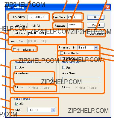
(1)IP Address
For setting the IP address of the unit.
(2)User Name (admin / operator / user)
For entering the user name for logging into the unit.
(3)Password (Within 8 letters)
13
For entering the password for logging into the unit.
(4)Unit Name (Within 32 letters) For entering the name of the unit.
(5)Video CH [1 ??? 4]
Turning on the ???Use??? check box enables use of the corresponding video channel.
(6)Audio Monitor
The audio input to
(7)Send Audio
Turning on the check box, operating the ???Send Audio??? button on the viewer application becomes possible. The audio input to PC can be transmitted to
(8)Camera Name (Within 32 letters)
For setting the camera name. The entered name appears on the live image.
(9)Size
For specifying the image size to give priority to during display or recording.
(10)Motion Detection
To use the motion detection alarm, turn on the check box.
When the check box is turned on, the name of the motion detection alarm is automatically set to ???Camera Name??? + ???Motion Detection???. This name cannot be altered.
(11)Serial Terminal [1 ??? 2]
Turning on the ???Use??? check box enables use of the corresponding serial terminal.
(12)Unit
For selecting the unit name connected with the serial terminal.
(13)Camera
For selecting the ???Video CH??? corresponding to the unit connected with the serial terminal.
(14)Alarm Terminal [1 ??? 4]
Turning on the ???Use??? check box enables use of the corresponding alarm terminal.
(15)Alarm Name (Within 32 letters)
For entering the name of the alarm. If the alarm name is left unspecified (blank) when the check box in (12) is turned on, this is automatically set to ???Camera Name??? + ???AL???? (??????? is the alarm number).
(16)Trigger
For selecting the method for determining the alarm.
(17)Web Setting Button
For displaying the Web Setting screen of the unit.
14
[For unit types other than
(4)
(5)
(11)
(12)
(13)
(14)
Setting Screen for Units Other Than
(1)IP Address
For setting the IP address of the unit.
(2)User Name (admin / operator / user)
For entering the user name for logging into the unit.
*It is displayed only for
(3)Password (Within 8 letters)
For entering the password for logging into the unit.
*Password setting is not available for
(4)Unit Name (Within 32 letters) For entering the name of the unit.
(5)Camera Name
This is automatically set to the same name as the unit name. This name cannot be altered.
(6)Motion Detection
To use the motion detection alarm, turn on the check box.
When the check box is turned on, the name of the motion detection alarm is automatically set to ???Camera Name??? + ???Motion Detection???. This name cannot be altered.
*Motion detection setting is not available for
*For
15
Alarm Setting??? (to be explained later).
(7)Request Mode (Normal / High Speed)
When "High Speed" is selected, the image is acquired in the
*It is displayed only for
*Please note the following points when you select "High Speed".
-The frame rate of the image transmitted from the camera to
-When the communication traffic between the camera and
-The client
(8)Audio Monitor
The audio input to
* It is displayed only for
(9)Send Audio
Turning on the check box, operating the ???Send Audio??? button on the viewer application becomes possible. The audio input to PC can be transmitted to
* It is displayed only for
(10)Alarm Terminal [1 ??? 2]
Turning on the ???Use??? check box enables use of the corresponding alarm terminal.
* For
(11)Alarm Name (Within 32 letters)
For entering the name of the alarm. If the alarm name is left unspecified (blank) when the check box in (6) is turned on, this is automatically set to ???Camera Name??? + ???AL???? (??????? is the alarm number).
(12)Trigger
For selecting the method for determining the alarm. * It is displayed only for
(13)Serial Terminal [1]
Turning on the ???Use??? check box enables use of the corresponding serial terminal. * It is displayed only for
(14)Unit
For selecting the unit name connected with the serial terminal. * It is displayed only for
(15)Web Setting Button
For displaying the Web Setting screen of the unit.
16
*When setting is complete, click the ???OK??? button to close the ???Unit Setting??? screen.
*To change the settings of a registered unit, select the unit to alter from the unit list, followed by clicking the ???Modify??? button.
*Screens and procedures when changing settings are similar to those for unit registration.
*To delete a registered unit, select the unit to delete from the unit list, followed by clicking the ???Delete??? button.
2.3.1.
*To use the alarm on
Example: Set No.01 to ???Alarm Input 1???, No.02 to ???Alarm Input 2???, and No.03 to ???Motion Detection???.
*Please change the setting of the firewall so that the
17

2.4. Camera Setting
* This used to perform various settings for video input units on the screen where the ???Camera Setting??? tab is selected.
Camera List
Up Button
Down Button
When the Camera Setting tab is selected
*Video channels that are registered via ???Unit Registration??? are displayed on the ???Camera List???.
*The order of this list indicates the order of display on the viewer application.
*To alter the order of display, select a camera, and click the ???Up??? or ???Down??? button to the right of the list. Alternatively, drag and drop the item using the mouse.
18
2.4.1. Camera Property Setting
*To alter the camera settings, select a camera, and click the ???Property??? button. Doing so enables setting as follows.
(1)
(2)
(3)
(4)
(5)
(6)
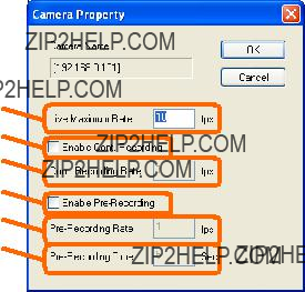
Camera Property Screen
(1)Live Maximum Rate (From
(2)Enable Cont. Recording
Tick to enable continuous recording.
(3)Cont. Recording Rate (From
(4)Enable
Tick to enable
(5)
(6)
(Precautions)
*If a negative value is set to the frame rate, second of the absolute value number becomes a frame interval. (Example:
*The frame rate is automatically adjusted according to the number of screens. As such, there are cases when images are not displayed using the frame rate set here.
*Frame rates have an impact on the record file storage period and CPU usage. Determine a frame rate upon taking the amount of disk space and CPU usage ratio into consideration.
*When the CPU usage ratio is below 60%, it is recommended that the amount of disk space allocated for the record file storage period be less than 70% of the total space.
19

2.4.2. Camera Display/Position Registration
*Select a camera from the list, followed by clicking the ???Camera Display/Position Registration??? button to display the ???Camera Display/Position Registration??? screen for checking the video images.
*When
*Procedures to register a position are as follows.
(1)Select the position number to register from the position list.
Selecting a position that has been registered beforehand moves display of the camera???s video image to that position.
(2)Control the camera by dragging the Position/Zoom Control area to display the image to register.
(3)Click the ???Register??? button.
(4)A screen for entering the position name appears. Enter a name (Within 32 letters).
When a position that has been registered beforehand is selected, the current position name appears. Alter this name accordingly.
(5)The current image is registered with the selected position.
*To delete a registered position, select the position to delete from the position list, followed by clicking the ???Delete??? button.
20
* To close the ???Camera Display/Position Registration??? screen, click the ???Close??? button.
(Precautions)
*In the case of
Each value of "Pan???, ???Tilt???, and ???Zoom" cannot be set though "Position Name" can be set. Moreover, the HOME position cannot be deleted.
Refer to "Instructions" of
*In the case of
Please select "Pattern 4/6/8" to which ???digital PTZ function??? of JPEG is effective by "Encode setting" of
When you change "Encode setting" after the position of
21

2.5. Alarm Event Registration
*This is used to control camera recording actions that are associated with alarm occurrences as ???alarm events???.
*Register alarm events on the screen where the ???Alarm Event Registration??? tab is selected.
*Alarm events that are registered in the ???Alarm Event List??? are displayed.
*To add a new alarm event, click the ???Register??? button.
The ???Alarm Event Registration??? screen appears. Register the alarm event by setting as follows.
22
(1) 
(2) 
(4)
(3)  (5)
(5)
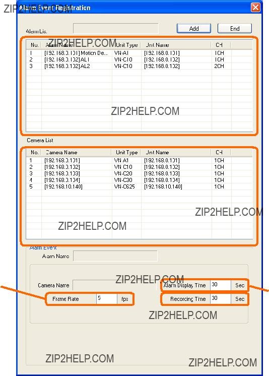
Alarm Event Registration Screen
(1)Alarm List
Select the alarm for which recording is to be triggered.
(2)Camera List
Select the camera to perform recording when an alarm occurs.
(3)Alarm Display Time (10 ??? 3600 seconds)
23

Set the time for displaying the alarm message on the live screen of the viewer application.
(4)Frame Rate (1 ??? 30 fps)
Set the frame rate for alarm recording.
(5)Recording Time (10 ??? 3600 seconds) Set the time for alarm recording.
*When setting is complete, click the ???Add??? button to add the alarm event.
*Repeat the same setting procedures to add subsequent alarm events.
*When adding is complete, click the ???End??? button to close the ???Alarm Event Registration??? screen.
*To change the settings of a registered alarm event, select the alarm event to alter from the alarm event list, followed by clicking the ???Modify??? button.
 Alarm Display Time
 Recording Time
Frame Rate
Alarm Event Modification Screen
*You can alter the frame rate, recording time, and alarm display time.
*When change is complete, click the ???OK??? button to close the ???Alarm Event Modification??? screen.
*To delete a registered alarm event, select the alarm event to delete from the alarm event list, followed by clicking the ???Delete??? button.
(Precautions)
*The image immediately after the alarm event might not be recorded by alarm recording. Please set
Refer to "2.4.1 Camera Property Setting" for
24

2.6. Schedule Registration
*This is used to manage the schedule for performing automatic recording on a specified date/time.
*Register the schedule on the screen where the ???Schedule Registration??? tab is selected.
Schedule Registration Tab
Delete Button
Modify Button
Register Button
* Schedules that are registered in the ???Schedule List??? are displayed.
25

*To add a new schedule, click the ???Register??? button. The ???Schedule Registration??? screen appears. Register the recording schedule by setting as follows.
(4)
 (6)
(6)
 (5)
(5)
 (7)
(7)
Schedule Registration Screen
(1)Duration
Select either ???Do not specify??? or ???Specify???.
(2)Start Day
Select the date for starting the scheduled action.
This is enabled only when the Duration item is set to ???Specify???.
(3)End Day
To specify the date for ending the scheduled action, turn on the check box and specify the ending date of the scheduled action. The period when "Year" was stepped over cannot be set.
This is enabled only when the Duration item is set to ???Specify???, and the ???End Day Check Box??? is turned on.
When you turn off "End Day Check Box", it is set as a schedule executed only on the day specified by "Start day".
(4)Repeat
(5)Time
Set the starting/ending time for the scheduled recording.
(6)Frame Rate (From
(7)Camera List
26
Select the camera to perform the scheduled recording.
*When setting is complete, click the ???OK??? button to close the ???Schedule Registration??? screen.
*To change the settings of a registered schedule, select the schedule to alter from the list, followed by clicking the ???Modify??? button.
*Screens and procedures when changing settings are similar to those for schedule registration.
*To delete a registered schedule, select the schedule to delete from the list, followed by clicking the ???Delete??? button.
27

2.7. User Registration
*Register the user on the screen where the ???User Registration??? tab is selected.
*Use the user name and password registered here to start up the viewer application.
User Registration Tab
Delete Button
Modify Button
Register Button
* Users that are registered in the ???User List??? are displayed.
28

*To add a new user, click the ???Register??? button.
The ???User Registration??? screen appears. Register the user by setting as follows.
(1) 
(2) 
(3) 
(4)
(5)
(6)
(7)
User Registration Screen
(1)User Name (Within 8 letters)
Enter the name of the user to be registered.
(2)Windows Authentication
The viewer application can be started without inputting the password when the login user name of Windows is corresponding to the user name of (1).
(3)Password (Within 8 letters)
Enter the password of the user to be registered.
(4)Control
To assign camera control authority to the user to be registered, turn on the check box.
(5)Playback Control
To assign playback control authority to the user to be registered, turn on the check box.
(6)Emergency Recording
To assign emergency recording execution authority to the user to be registered, turn on the check box.
(7)Export
To assign AVI export execution authority to the user to be registered, turn on the check box.
*When setting is complete, click the ???OK??? button to close the ???User Registration??? screen.
*To change the settings of a registered user, select the user to alter from the user list, followed by clicking the ???Modify??? button.
*Screens and procedures when changing settings are similar to those for user registration.
29

*To delete a registered user, select the user to delete from the user list, followed by clicking the ???Delete??? button.
2.8. Reflection of Settings
Setting Start Button
*When the settings are complete, click the ???Setting Start??? button to reflect the settings.
*Setting is complete when the ???Output in progress. Please wait for a moment...??? screen disappears.
2.9. Exiting the Setup Tool
End Button
* Use the ???End??? button to exit the setup tool.
2.10. Starting Up the Viewer Application
*
*Refer to the
30
3. Other Controls
3.1. Restarting the Service
* One of the emergency measures to take when system abnormalities occur, such as when images are not renewed or recorded, is to restart the various groups of services.
* To restart the various groups of services, click [Start] ??? [All Programs] ??? [JVC] ???
3.2. Terminating (Starting) the Service
*To stop recording or transmission, such as during maintenance of the disk or network, terminate the various groups of services.
*To terminate the various groups of services, click [Start] ??? [All Programs] ??? [JVC] ???
*To restart after maintenance is complete, click [Start] ??? [All Programs] ??? [JVC] ???
31
4. Backup and restoration
Please kindly refer to the instruction manual of each backup software regarding the detailed procedure both backup and restoration.
When you use
4.1. Files to be backed up
The search and playback of recording data at the backup are possible by backup and restoring the following files.
(1)Configuration file
All in the following folders (Windows XP/Server 2003)
???C:??Documents and Settings??All Users??Application Data??JVC??SCoF??conf??? (Windows Vista)
???C:??ProgramData??JVC??SCoF??conf???
(2)Alarm data base
All in the following folders (Windows XP/Server 2003)
???C:??Documents and Settings??All Users??Application Data??JVC??SCoF??db??? (Windows Vista)
???C:??ProgramData??JVC??SCoF??db???
(3)Recording data
All in folder set to ???System Setting??? - ???Recording File Folder???
4.2. Limitations
Please note that there are the following limitations (notes).
(When you use Windows Vista)
???The following script files (BackupAlarmDb.bat and RestoreAlarmDb.bat) are made by using the path name for ???Windows XP/Server 2003???. Please use it for ???Windows Vista??? after correcting the path name.
(When you use OS other than an English version)
???Please change the path name in the following script files (BackupAlarmDb.bat and RestoreAlarmDb.bat) correctly when the path name is different from the
32
(The alarm data base is backed up.)
???It is necessary to stop the service of the data base of
*Refer to 4.3 (1), (2)
(Restoration and Search)
???While
???When restoring and searching for old data, the operation that stops this function is needed because the function to delete old data works by setting ???System Setting??? ??? ???Recording File Keeping Period???.
*Refer to 4.3 (3)
???When the configuration file is restored, the restart of all services is needed.
*Refer to 4.3 (3)
4.3. Method of operating related function of
(1)Data base function how to stop when backing up
??? The backup of the alarm data base backs up
When backing up, it is necessary to stop the service of the data base of
???There is the following procedure as a method of shortening the stop period of the data base service. 1). Stop the data base service
2). Copy
4). Back up file
???The script file that does
"C:??Program Files??JVC??SCoF??bin??" as "BackupAlarmDb.bat".
(2)Method of restoring data base when restoring it
???When searching,
???Please execute "RestoreAlarmDb.bat" of "C:??Program Files??JVC??SCoF??bin??".
(3)Unnecessary function how to stop in PC to execute restoration and search
???It is necessary to stop the following functions when searching and playing on not PC that executes the record but another PC.
--Acquisition of camera image (extra load of communication traffic and camera)
--Deletion function of old image
???Please execute "InstallPlayOnly.bat" of "C:??Program Files??JVC??SCoF??bin??" to install
33
???Please execute "UninstallPlayOnly.bat" of "C:??Program Files??JVC??SCoF??bin??" to return the regular version the
(4)Method of restarting all services
???It is necessary to restart service to reflect the setting in service after the configuration file is restored.
???To restart the various groups of services, click [Start] ??? [All Programs] ??? [JVC] ???
4.4. Example of backup procedure
(1) The backup of the setting, and the replacement and restoration of PC
(Backup)
1.After it initializes it, the configuration file of "4.1 (1)" is copying backed up. (Restoration)
2.The
3.???1.??? is restored to new PC.
4.New PC is restarted. (Refer to 4.3 (4))
(2)Regular backup of image data and playback on another PC
(Backup)
1.To execute "BackupAlarmDb.bat" regularly, it registers in "System Tools" - "Scheduled Tasks" of Windows.
2.To back up
3.The
(Playback on another PC)
4.The backup data of ???2.??? is restored to
5.The file name of
6.Each service of
7.
*???The search and playback of the record image become possible when the camera is selected and it switches to "View Records" screen though a live image of the camera is not displayed.
34
5. Operating Suggestions
5.1. Personal computer setting
Do not set your computer to enter ???System standby??? or ???System hibernates??? mode when
5.2. Concerning the CPU load
The frame rate of the image recorded at that time might decrease when processing with a high CPU load is done with the personal computer
5.3. Concerning the recording file save location (hard disk drive) and file save period
It is recommended to use a different disk drive for the recording file save location from the OS system's drive.
Additionally the NTFS is recommended for the file system of the disk drive which has the file save location. FAT/FAT32 may sometimes make the recording impossible because of its limitation of the number of files per a folder.
For the stable performance with recordings over the long term, defragment the disk drive regularly. Keep the disk drive 70% or less occupied by deleting old recording files using effectively the file save period setting. This operation also avoids the fragmentation of the disk drive. (See ???2.2 System Setting??? ???Recording File Keeping Period??? and ???Deletion Starting HDD Capacity???)
5.4. Concerning the adjustment of the time of PC
When you return the time of PC at past time, the recorded recording data is overwritten by recording the data of the same time. Moreover, when you advance the time of PC at time of the future, continuous image data is recorded as discontinuous recording data.
When adjusting it at time, the recording stop and the recording data are recommended to be backed up referring to ???3.2 Terminating (Starting) the Service??? or ???4 Backup and restoration???.
35

COPYRIGHT ?? 2008 Victor Company of Japan, Limited
36