R

UPCONVERTER HDTV D2300U-BC

HDTV UPCONVERTER

BC-D2300U INSTRUCTIONS

BC-D2300U HDTV UP CONVERTER

POWER STATUS INPUT SYNC

ENTER ESC

LOCAL REMOTE

MENU

R

VICTOR COMPANY OF JAPAN, LIMITED

Thank you for purchasing this JVC product. Before operating this unit, please read the instructions carefully to ensure the best possible performance.

For Customer Use:

Enter below the Serial No. which is located on the top cover. Retain this information for future reference.

Model No. BC-D2300U

Serial No.

This instruction book is made from 100% recycled paper.

SAFETY PRECAUTIONS

1.Read all of these instructions.

2.Save these instructions for later use.

3.All warnings on the product and in the operating instructions should be adhered to.

4.Unplug this appliance system from the wall outlet before cleaning. Do not use liquid cleaners or aerosol cleaners. Use a damp cloth for cleaning.

5.Do not use attachments not recommended by the appliance manufacturer as they may cause hazards.

6.Do not use this appliance near water ??? for example, near a bathtub, washbowl, kitchen sink, or laundry tub, in a wet basement, or near a swimming pool, etc.

7. Do not place this appliance on an unstable cart, stand, or table. The appliance may fall, caus- ing serious injury to a child or adult, and serious damage to the appliance.

Use only with a cart or stand recommended by the manufacturer, or sold with the appliance.

Wall or shelf mounting should follow the manufacturer???s instructions, and should use a mount- ing kit approved by the manufacturer. An appliance and cart combination should be moved with care. Quick stops, excessive force, and uneven surfaces may cause the appliance and cart combination to overturn.

8. Slots and openings in the cabinet and the back or bottom are provided for ventilation, and to insure reliable operation of the appliance and to protect it from overheating, these openings

must not be blocked or covered. The openings should never be blocked by placing the appliance on a bed, sofa, rug, or other similar surface. This appliance should never be placed near or over a radiator or heat register. This appliance should not be placed in a built-in installation such as a bookcase unless proper ventilation is provided.

CAUTION

RISK OF ELECTRIC SHOCK

DO NOT OPEN

CAUTION: TO REDUCE THE RISK OF ELECTRIC SHOCK,

DO NOT REMOVE COVER (OR BACK).

NO USER-SERVICEABLE PARTS INSIDE.

REFER SERVICING TO QUALIFIED SERVICE PERSONNEL

The lightning flash with arrowhead symbol, within an equilateral triangle, is intended to alert the user to the presence of uninsulated ???dangerous voltage??? within the product???s enclosure that may be of sufficient magnitude to constitute a risk of electric shock to persons.

The exclamation point within an equilateral triangle is intended to alert the user to the presence of important operating and maintenance (servicing) instructions in the literature accompanying the appliance.

WARNING:

TO REDUCE THE RISK OF FIRE OR ELECTRIC

SHOCK, DO NOT EXPOSE THIS APPLIANCE

TO RAIN OR MOISTURE.

This unit should be used with 120 V AC only.

CAUTION:

To prevent electric shocks and fire hazards, do NOT use any other power source.

NOTE:

The rating plate (serial number plate) is on the top cover.

INFORMATION

This equipment has been tested and found to comply with the limits for a Class A digital device, pursuant to Part 15 of the FCC Rules. These limits are designed to provide reasonable protection against harmful interference when the eqipment is operated in a commercial environment. This equipment generates, uses, and can radiate radio frequency energy and, if not installed and used in accordance with the instruction manual, may cause harmful interference to radio communications.

Operation of this eqipment in a residential area is likely to cause harmful interference in which case the user will be required to correct the interference at his own expense.

CAUTION

CHANGES OR MODIFICATIONS NOT APPROVED BY JVC

COULD VOID USER???S AUTHORITY TO OPERATE THE

EQUIPMENT.

ATTENTION

RISQUE D'ELECTROCUTION

NE PAS OUVRIR

ATTENTION: POUR EVITER TOUT RISQUE D'ELECTROCUTION

NE PAS OUVRIR LE BOITER.

AUCUNE PIECE INTERIEURE N'EST

A REGLER PAR L'UTILISATEUR.

SE REFERER A UN AGENT QUALIFIE EN CAS DE PROBLEME.

Le symbole de l????? clair ?? l???int??rieur d'un triangle ??quilat??ral est destin?? ?? alerter l???utilisateur sur la pr??sence d???une ???tension dangereuse??? non isol??e dans le bo??tier du produit. Cette tension est suffisante pour provoquer l?????lectrocution de personnes.

Le point d???exclamation ?? l???int??rieur d???un triangle ??quilat??ral est destin?? ?? alerter l???utilisateur sur la pr??sence d???op??rations d???entretien importantes au sujet desquelles des renseignements se trouvent dans le manuel d???instructions.

*Ces symboles ne sont utilis??s qu???aux Etats-Unis.

AVERTISSEMENT:

POUR EVITER LES RISQUES D'INCENDIE OU

D'ELECTROCUTION, NE PAS EXPOSER

L'APPAREIL A L'HUMIDITE OU A LA PLUIE.

Ce magn??toscope ne doit ??tre utilis?? que sur du courant alternatif en 120 V.

ATTENTION:

Afin d'??viter tout resque d'incendie ou d'??lectrocution, ne pas utiliser d'autres sources d'alimentation ??lectrique.

REMARQUE:

La plaque d'identification (num??ro de s??rie) se trouve sur le panneau arri??re de l'appareil.

HANDLING

PRECAUTIONS

???Avoid using this unit in places subject to the following conditions:

???direct sunlight

???high humidity and dust

???vibrations

???extreme heat

These conditions can cause problems and may damage the unit.

CONTROLS, INDICATORS AND

CONNECTORS

Front panel

BC-D2300U HDTV UP CONVERTER

POWER STATUS INPUT SYNC

ENTER ESC

LOCAL REMOTE

MENU

This unit converts SMPTE259M-standard SD digital serial signal input to the SMPTE292M-standard (1080I or 720P) HD digital serial signal for output.

Conversion modes are provided for input NTSC video signals with an aspect ratio of 4:3 (standard), in the letter box format or squeezed.

The delay time for video conversion is added to the embedded audio to synchronize audio and video for output.

Input signal can be cropped (in the 4:3 mode, independently for the left and right sides)

Background color can be set with hue, saturation and lightness.

It is possible to set or show the model name (up to 10 characters).

Each function can be set on the front panel with the LCD. The unit can also be remote-controlled via the 9-pin connector on the rear panel (RS-485 or RS-232C).

Menu settings can be saved in memory and loaded from memory.

Four independent memories are provided to store menu settings. Stored menu settings can be recalled as required.

Compact design allows this unit to be installed in a 1U EIA rack.

Color bar output possible.

External reference sync signal input connector

Three video/audio output connectors

Enhancer (contour correction), motion sensitivity, background color, screen horizontal/vertical position and system phase can be adjusted.

Error indication and alarm signal output function

Color correction function (option)

Variable enhancer (option)

NOTES ON SETTINGS

AND USE

INSTALLATION IN A

RACK

This unit can be installed in EIA standard rack. Ensure sufficient rack strength by attaching L-metal supports on both sides of the rack on which you will place the unit.

1.Detach the four feet on the base of the unit.

2.Install the supplied rack mount brackets on both sides of front panel using the four supplied screws (M4).

3.Set this unit on the rack, and fix the rack mount brackets onto the rack using the four supplied screws (M5).

2.Rack mount bracket

10

1[POWER] indicator

Lights green when power is supplied to this unit.

2[STATUS] indicator

Normally lights green. Lights orange in the menu setting mode, when the set value is changed or the set data is transmitted to this unit. When the transmission is complete, this indicator lights green again. When errors occur in hardware, etc., this indicator lights red.

3[INPUT] indicator

Normally lights green. When no signal is input, this indicator lights orange. If there is an error in the input signals, this indicator lights red.

4[SYNC] indicator

Normally lights green. If a sync system-related error occurs, this indicator lights red.

??? For details on error indicators, see page 17.
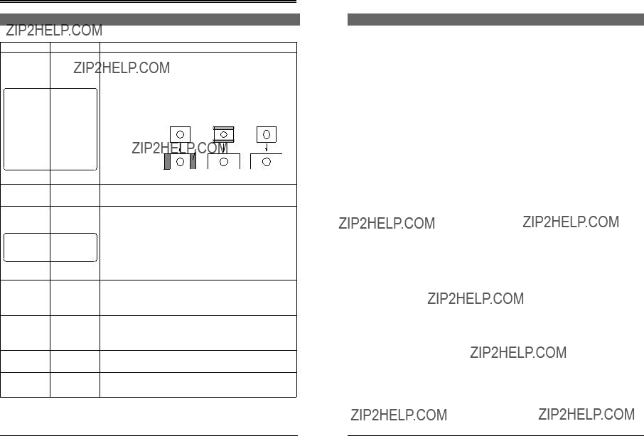
5Display

???When power is applied, the input/output or screen display mode is shown. (Normal display mode)

Model name:

The model name can be set with the menu (up to 10 characters). In the remote mode, the remote ID number (1 ??? 31) is shown following the model name.

(e.g.) BC-D2300 ID: 

B C ??? D 2 3 0 0

[ D 1 | 1 0 8 0 | 4 : 3 ]

Input form Output form Screen conversion mode

Memoranda:

???The screen conversion mode can be selected with menu <Output Mode>.  p. 10.

???Output form can be selected with menu <Output>.  p. 10.

???When menu <Color Correction> is set to ???ON??? or <Colorimetry> is set to ???OFF???, the normal display changes as follows.

6

6[+/???] button

Press this button to change the set value for a menu item in the menu setting mode.

7 [/] button

Press this button to select the menu item in the menu setting mode.

8[ENTER/MENU] button

???In the normal display mode, press this button to engage the menu setting mode.

???In the menu setting mode, press this button to enter the set value for the following menu items. (? is shown.)

Output Mode item Output item Profile Save item Profile Load item

???Use to enter the sub menu. ([ENTER] is shown.)

9[ESC] button

In the menu setting mode, press this button to restore the normal display mode.

Memorandum:

??? To use the menu setting, refer to pages 7 to 9.

0[LOCAL/REMOTE] switch

Use to select LOCAL or REMOTE to operate this unit. LOCAL : Set to this position to operate this unit with

the operation buttons on this unit.

REMOTE : Set to this position to remote-control this unit via the [REMOTE IN] connector or [ALARM] connector on the rear panel. Also, set to this position to lock the front panel???s operation buttons.

??? The factory preset is LOCAL.

???When the menu item <Reference> is set to [INPUT] and there is no SD input signal, output video signals may be distorted. In this

case, input external sync signals and set <Reference> to [BB] or [HD-SYNC]. ( p. 10).

???When the menu item <Reference> is set to [BB] or [HD-SYNC] and these external sync signals are not input or are incorrect, output video signals may be distorted. In this case, system phase cannot be assured. ( p.10)

 See ??????Supplement?????? on page 21.

B C ??? D 2 3 0 0

[ D 1 / 1 0 8 0 / 4 : 3 ]

Change

???Press the 8 [ENTER/MENU] button to display the item in the menu setting mode.

???If an error occurs in the normal display mode, a description of the error is shown.  p. 17.

CONTROLS, INDICATORS AND CONNECTORS

Rear panel

MENU SETTINGS

You can set various functions on the menu. Settings are stored and automatically activated whenever you turn on the power. Up to four independent menu settings can be stored in the unit???s memory and recalled at any time. You can also restore the default factory settings at any time. The menu is shown on the display.

Setting the menu

POWER STATUS INPUT SYNC

LOCAL REMOTE

BC-D2300U HDTV UP CONVERTER

ENTER ESC

1[AC IN] power input connector

Connect to an AC 120 V, 50 Hz/60 Hz power outlet with

the provided power cable. Attach the provided hook beforehand.  p. 18.

2[POWER] switch

Use to turn the power on/off. When the power is turned on, the indicators and display on the front panel light up.

3Fuse holder

The fuse is built in. For fuse replacement, consult your nearest JVC dealer.

4[SDI IN] connector

Input a SMPTE259M standard SD digital serial signal (NTSC). Compatible with embedded audio signals as well. Embedded 20-bit digital audio with 48 kHz sampling frequency can be input with 4 channels.

5 [SDI OUT] connector

Active through output of digital serial video/audio signals input to the 4 [SDI IN] connector is possible.

6[CVBS] connector

Input analog composite signals (NTSC). The optional BC-D231 (D2/analog optional board) is required.

7 [Y/Pr/Pb] connectors

Input analog component signals (NTSC) to each connector. The optional BC-D231 (D2/analog optional board) is required.

Note:

???The [CVBS] and [Y/Pr/Pb] connectors are enabled only when the BC-D231 optional board is installed. For details, refer to the BC-D231 instruction manual.

9[HD SERIAL OUT] HD digital serial output connectors (3 lines)

Output SMPTE292M standard HD digital serial signals. Output embedded digital audio signals with 20-bit

48 kHz sampling frequency as 4-channel signals.

0[ALARM] connector ... D-sub 9-pin (male)

???This connector is an alarm output (relay contact) connector. When a problem occurs with this unit, an alarm signal is output.

???When menu switch <Remote Port> is set to ???ALARM???, remote operation via the RS-232C is possible.

To remote-control this unit via this connector, set the [LOCAL/REMOTE] switch on the front panel to ???REMOTE???.

![REMOTE-IN] connector ... D-sub 9-pin (female)

This connector is the input connector for remote-control device.

Connect this connector to a device conforming to the RS-485 serial interface standard.

Memoranda:

???To use this connector, set menu switch <Remote Port> to ???REMOTE-IN???.

???Set the remote ID and remote transmission speed with the menu switches.

???To remote-control this unit, set the [LOCAL/REMOTE] switch on the front panel to ???REMOTE???.

Normal display

3[] button 6 [ESC] button

1Turn the power of this unit ON.

The model name, input/output and screen display mode are shown on the display (normal mode).

2Press the [ENTER/MENU] button to engage menu setting mode.

??? The display shows the menu. The current setting is shown.

3Press the [] or [] button to select the menu item.

4Press the [+] or [???] button to change the setting.

Memoranda:

???When ???[??? is shown at the right of the display, press the [+] button to change the setting. When ???p???is shown at the left of the display, press the [???] button.

???When ???????appears after the value you want to set, press the [ENTER/MENU] button to enter the setting.

???When the setting is changed, the [STATUS] indicator lights orange while the set data is transmitted to this unit. When the transmission is complete, this indicator lights green.

Refer to the next page for details on how to store menu setting contents in memory.

5Press the [ESC] button to end menu setting.

??? Your changes are stored in memory and the display returns to

normal.

Note:

If power is turned OFF without pressing the [ESC] button, setting changes are not saved.

8[REF] external reference sync signal input connectors (loop-through)

Input external reference sync signal. As these connectors use a loop-through system, signals input to one connector can be distributed from another connector to the other equipment.

Memoranda:

???When signal distribution is not required or this unit is a terminating device, terminate this unit with the external 75-ohm terminator.

???When the signals input to these connectors are used

as a reference sync signal, set the menu switch <Reference> to ???B.B??? or ???HD SYNC???.  p. 10.

???When the signals input to these connectors are used as a reference sync signal, synchronize the input signal with the reference sync signal so that the V sync is within ??300 ??s.

#[TERMINATE] switch

This is the terminating switch for remote control signals. With a series connection, set this switch to ???ON??? when this unit is terminated or control signals from the [ALARM] connector are received.

??? The factory preset is ???OFF???.

Sub menu

Menu display

Exact settings for variable enhancer (option), color correction (option) and administration can be done on the sub menu.

1.When setting the variable enhancer or color correction to ON, or selecting administration, [ENTER] is shown on the display. To enter the sub menu, press the [ENTER/MENU] button.

2.Set each menu item in the same way as with the ordinary menu.

3.Press the [ESC] button to go to the upper menu by one.

MENU SETTINGS

Storing menu settings in memory of this unit

Entering characters

Normal display

1Press the [ENTER/MENU] button to engage the Menu Display mode.

2Select Profile Save with the [] or [] button.

Enter characters to set the model name and the [License key].

P r o f i l e S a v e

MEMOR Y 2 ?

ENTER/MENU

3Select the memory number where you want to store the menu settings with the [+] or [???] button (one of MEMORY 1 to 4).

??? The ??????? is added to the end of the selected memory number.

4Press the [ENTER/MENU] button.

??? The check screen is shown for confirmation.

5Press the [ENTER/MENU] button again to confirm the setting.

???The menu settings are stored in the selected memory. Once the settings have been stored, the completion screen is shown.

Memorandum:

???When the check screen is shown, press the [ESC] button to cancel it. The previous Profile Save menu setting display is restored.

POWER STATUS INPUT SYNC

LOCAL REMOTE

Name menu display

BC-D2300U HDTV UP CONVERTER

ENTER ESC

MENU

An example of model name setting is shown below.

1Select [Name] in the sub menu for administration.

??? The currently-set device name is shown.

Completion screen

P r o f i l e S a v e

S a v e d .

ENTER/MENU or ESC

6Press the [ENTER/MENU] button or [ESC] button.

??? Menu setting display is restored.

7Press the [ESC] button to restore the normal display.

Note:

???Settings for Remote ID, Remote Speed and Remote Port are not stored in memory for each Profile. One value is used for all profiles.

3Move the cursor with the [+] or [???] button.

Change the characters with [] or [] button (up to 10 characters).

4Press the [ENTER/MENU] button to store the device name in memory.

???The setting is refreshed and the name menu display is restored.

Recalling stored menu settings or factory default settings

Normal display

B C ??? D 2 3 0 0

[ D 1 | 1 0 8 0 | 4 : 3 ]

ENTER/MENU

ESC

Profile Load

Menu display

1Press the [ENTER/MENU] button to engage the Menu Display mode.

2Select Profile Load with the [] or [] button.

3Select the memory to be recalled (MEMORY 1 to 4, DEFAULT) with the [+] or [???] button.

When DEFAULT is selected, the factory setting is recalled.

5To restore the normal display, press the [ESC] button.

4Press the [ENTER/MENU] button.

??? Display the check screen for confirmation.

5Press the [ENTER/MENU] button again to confirm.

???The selected settings are recalled. When completed, the completion display is shown.

Memorandum:

???When the check screen is shown, press the [ESC] button to cancel it. The previous Profile Load menu setting display is restored.

6Press the [ENTER/MENU] button or [ESC] button.

???Menu setting display is restored and the recalled menu settings are activated.

7Press the [ESC] button to restore the normal display.

Memorandum:

??? The factory default settings are stored in MEMORY 1 to 4.

MENU SETTINGS

Menu contents

Note:

???The following menu item values can be saved for each setting mode.

???V Position

???Motion Sense

???Enhance Level

???Variable Enhancer and 5-related item (option)

When the setting for Output Mode is changed, check the setting of the above menu items.

Note:

???System Phase settings can be saved for each of these item settings.

[ ]: Factory Setting

Contents

Sets the HD Conversion mode according to the NTSC video source.

4 : 3: When the input video has an aspect ratio of 4:3, it is converted to HD pictures without changing the aspect ratio for output. In this case, the side panels appear on the screen.

LETTER BOX : When the input video is in the LETTER BOX format, it is converted to HD pictures with an aspect ratio of 16:9 for output.

SQUEEZE : When the input video has been ???squeezed??? for display on 4:3 screens, it is converted to HD pictures with an aspect ratio of 16:9 for output.

4 : 3LETTER BOX SQUEEZE

NTSC

Side panel

HD

Sets the output video format.

Selects the reference sync signal.

INPUT : Synchronizes with the video signal input to the [SDI IN] connector of this unit.

BB: Synchronizes with the black burst signal input to the [REF] connector of this unit.

HD-SYNC : Synchronizes with the tri-sync input to the [REF] connector of this unit. Tri-sync must be input in the same signal form as the output setting.

Note:

???When this is set to ???BB??? or ???HD-SYNC???, the V sync position of these external signals and video input signals must synchronize within ??300 ??s..

Sets the HD output signal phase for the reference sync signal selected with <Reference>.

(Variation for ??300 is equivalent to about ??4 ??s.)

Adjusts the picture???s horizontal display position (varies in ??120 x 2 pixels).

???This item is enabled only when the Output Mode is set to 4:3.

???When the <Output> item is set to ???720P???, the actual display position area is ??80 x 2 pixels. Keep in mind that this is different from the value set with the menu.

Sets the crop width at the left of the input picture.

???This item is enabled only when the Output Mode is set to 4:3. For the part cropped, the background color is shown.

Sets the crop width at the right of the input picture.

???This item is enabled only when the Output Mode is set to 4:3. For the part cropped, the background color is shown.

Menu contents (contd.)

MENU SETTINGS

Menu contents (contd.)

[ ]: Factory Setting

Menu contents (contd.)

MENU SETTINGS

Menu contents (contd.)

Menu contents (contd.)

See "1.4 About Error Messages"

OTHERS

When an abnormality is detected, error notification is provided by LED illumination, error indication on the display and error output to the [ALARM] connector.

Error output (contd.)

Error indications and output contents

Error output

STATUS INPUT SYNC

Front panel

BC-D2300U HDTV UP CONVERTER

POWER STATUS INPUT SYNC

ENTER ESC

MENU

Error indication

Display

1. LED lighting

The [STATUS], [INPUT] or [SYNC] indicator on the front panel lights orange (warning) or red (error), depending on the type of error.

2. Display indication

The first line of the display shows a description of the error. When the menu is displayed, errors are not shown.

Memoranda:

???With LOCAL, the error indication is shown when the error is detected and goes out when the error is no longer detected. With REMOTE, once an error is detected, the indication remains (goes out when the switch is set to LOCAL).

???Error codes with 2 to 6 digits may be shown at the same time. In this case, report the error codes to your JVC dealer.

Rear panel

1 5

69

ALARM

3. [Alarm] connector output

2-line alarm output terminals are provided for the rear panel???s [ALARM] connector. Terminals A and B are short-circuited (relay contact) when an error occurs or the power is turned off. Normally, these terminals are open. (For open and short-circuited conditions, refer to the table on the next page.)

The maximum rated value is 30 V 0.5 A for AC/DC with non- inductive load.

Pin assignment of the [ALARM] connector

Note: When an incorrect external sync signal is input, the REF No-input error indication may be shown.

When an error indication is shown, check the input signal and connections according to type of error indicated. When this unit malfunctions, consult your nearest JVC authorized service agent.

on page 1-3.

OTHERS

Rear panel connectors

Specifications

 REMOTE-IN, REMOTE-OUT terminal pin assignment

5 1

96

Note:

???For the REMOTE connection, use a straight cable which contains twisted paired lines for the signals of TxA and TxB, RxA and RxB.

Installing the power cable hook

1.Before connecting the power cable, install the supplied hook as shown on the left.

2.After connecting the power cable, lower the hook to secure the power cable in place.

Hook

OTHERS

Specifications (contd.)

5 External dimensions (unit: mm)

Design and specifications subject to change without notice.

Supplement

 Attaching the L-metal support on EIA rack

L-metal support

Screw

Thickness: 2 mm

WARNING :

???Rack mounting is optional. Use only with racks that have fully adjustable vertical rack rails.

???Use the rack mount brackets (eras) and L-metal supports together.

Do not use only the rack mount brackets (ears) by themselves for support.

23