AUDIO/ VIDEO CONTROL RECEIVER
RX-1024VBK
COMPULINK
Remote
RM-SR1024U REMOTE CONTROL
D I G I T A L
INSTRUCTIONS
For Customer Use:
Enter below the Model No. and Serial No. which are located either on the rear, bottom or side of the cabinet. Retain this information for future reference.
Model No.
Serial No.
LVT0018-001A
To get the best DSP (Digital Signal Processor) effect in your listening room, note the speaker settings you have set on the table below for future reference (even though the receiver memorizes the settings until you change them).
For actual setting procedures, see pages 19 to 21.
Note:
If the power cord is unplugged or a power failure occurs, all preset settings will be erased in a few days.


 Getting Started
This section explains how to connect audio/video components and speakers to the receiver, and how to connect the power supply.
Before Installation
General
???Be sure your hands are dry.
???Turn the power off to all components.
???Read the manuals supplied with the components you are going to connect.
Locations
???Install the receiver in a location that is level and protected from moisture.
???The temperature around the receiver must be between 23?? and 95?? F (???5?? and 35?? C).
???Make sure there is good ventilation around the receiver. Poor ventilation could cause overheating and damage the receiver.
Handling the receiver
???Do not insert any metal object into the receiver.
???Do not disassemble the receiver or remove screws, covers, or cabinet.
???Do not expose the receiver to rain or moisture.
Checking the Supplied Accessories
Check to be sure you have all of the following items, which are supplied with the receiver.
The number in the parentheses indicates quantity of the pieces supplied.
???Remote Control (1)
???Batteries (2)
???AM Loop Antenna (1)
???FM Antenna (1)
If anything is missing, contact your dealer immediately.
Getting Started
Connecting the FM and AM Antennas
FM Antenna Connections
ANTENNA
FM 75
FM
GND
GND
AM
LOOP
AM
EXT
FM Antenna
Extend the FM wire antenna horizontally.
4
Outside FM Antenna Wire
 13/16 in.
(10 mm)
Note:
If reception is poor, connect the outside antenna.
Before attaching a 75?? coaxial cable (the kind with a round wire going to an outside antenna), disconnect the supplied FM wire antenna.
(20 mm)
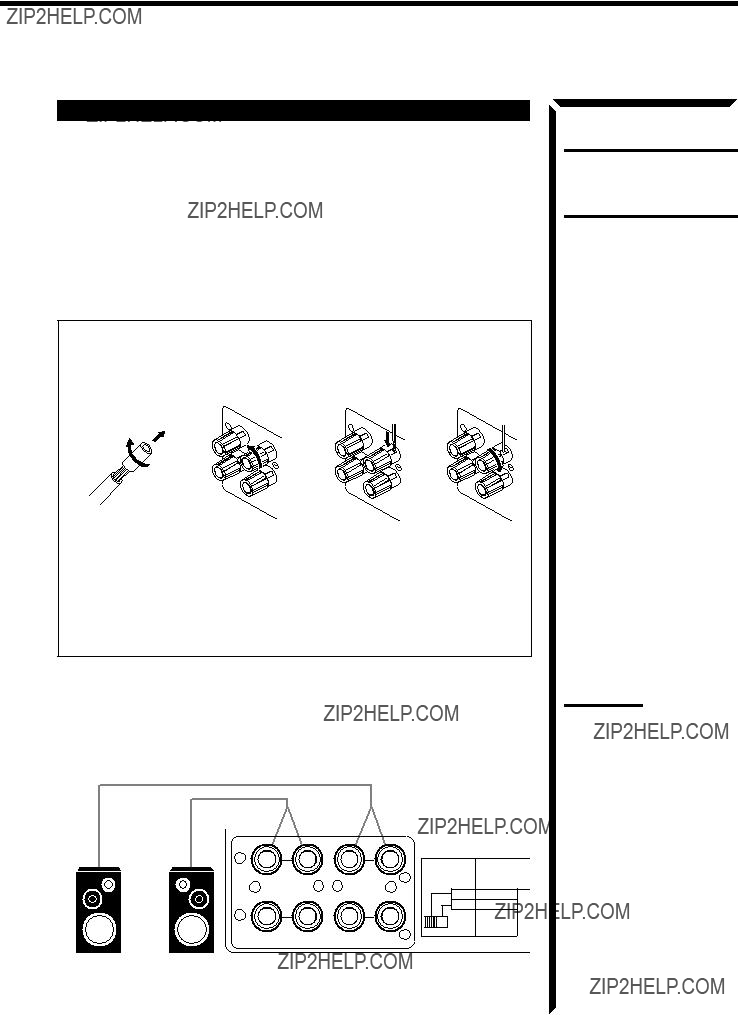
How to strip the 75?? coaxial cable and connect it to the FM terminals
1. Strip back the outside covering of the 75?? coaxial cable to expose the braided metallic mesh about 13/16 inches (20 mm).
2. Pull the mesh back and twist it into a single connector as shown in the illustration above.
3. Strip the insulation about 7/16 inches (10 mm) back from the central wire.
4. Insert the twisted mesh and the central wire to the FM terminals, as shown in the illustration above.
AM Antenna Connections
FM 75
FM
GND
AM Loop Antenna
GND
AM
LOOP
AM
EXT
Snap the tabs on the loop into the slots of the base to assemble the AM loop.
Outdoor single vinyl- covered wire
Getting Started
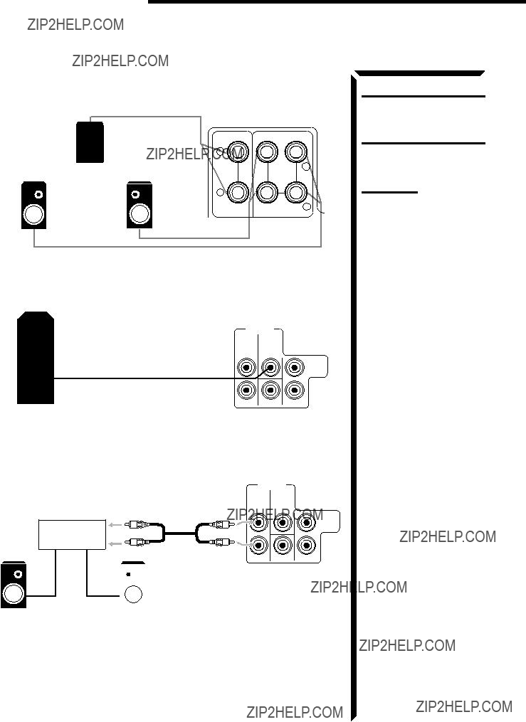
Digital connections
This receiver is equipped with three DIGITAL IN terminals ??? one digital coaxial terminal and two digital optical terminals.
To enjoy Dolby Digital, you have to connect the source components using the DIGITAL IN terminals.
You can connect any component to any one of the digital terminals using the digital coaxial cable (not supplied) or digital optical cable (not supplied).
When the component has a digital coaxial output terminal, connect it to the DIGITAL1 (DBS) terminal, using the digital coaxial cable (not supplied).
DIGITALIN
PCM/DOLBYDIGITAL
When the component has a digital optical output terminal, connect it to the DIGITAL2 (DVD) or DIGITAL3 (CD) terminal, using the digital optical cable (not supplied).
Before connecting a digital optical cable, unplug the protective plug.
DIGITAL1(DBS)
DIGITAL2(DVD)
DIGITAL3(CD)
IMPORTANT:
???When connecting the DVD player or the DBS tuner using the digital terminal, you also need to connect it to the video jack (either composite video terminal or S-video terminal) on the rear. Without connecting it to the video jack, you can view no playback picture.
???After connecting the above components using the DIGITAL IN terminals, set the following correctly if necessary.
???Select the digital input mode correctly. For details, see ???Selecting the Input Mode??? on page 17.
???Set the digital input (DIGITAL IN) terminal setting correctly. For details, see ???Digital Input (DIGITAL IN) Terminal Setting??? on page 19.
From the remote control:
Selecting different sources for picture and sound
You can watch picture from a video component while listening to sound from another component.
Note:
When you press one of the source selecting buttons marked above with an asterisk (*), the receiver automatically turns on.
Notes:
On the front panel:
1.Press SOUND SELECT briefly while viewing the picture from a video component such as the VCR or DVD player, etc. ???SOUND SELECT??? appears on the display.
2.Turn SOURCE SELECTOR to select the sound (except the TV sound), while the indication of the above step is still on the display.
From the remote control:
SOUND SELECT
INPUT ATT.
SOURCE SELECTOR
Press one of the audio source selecting buttons (CD, TAPE/MD, PHONO, FM, AM), while viewing the picture from a video component such as the VCR or DVD player, etc.
Adjusting the Volume
On the front panel:
To increase the volume, turn MASTER VOLUME clockwise.
CAUTION:
Always set the volume to the
minimum before starting any
To decrease the volume, turn it counterclockwise.
source. If the volume is set at its high level, the sudden blast of
When you turn MASTER VOLUME rapidly, the volume level also changes rapidly.
When you turn MASTER VOLUME slowly, the volume level also changes slowly.
From the remote control:
To decrease the volume, press VOLUME ???.
sound energy can permanently damage your hearing and/or ruin your speakers.
Note:
The volume level can be adjusted within the range of ???0??? (minimum) to ???90??? (maximum).
Attenuating the Input Signal
When the input level of the playing source through the analog terminals is too high, the sounds will be distorted. If this happens, you need to attenuate the input signal level to prevent the sound distortion.
On the front panel only:
Press and hold SOUND SELECT/INPUT ATT until ???INPUT ATT ON??? appears on the display.
The ATT indicator also lights up on the display.
Each time you press and hold the button, the input attenuator mode turns on (???INPUT ATT ON???) and off (???INPUT NORMAL???).
You can set input attenuator mode separately for each source.
Adjusting the Subwoofer Output Level
You can adjust the subwoofer output level if you have selected ???YES??? for the ???SUBWOOFER??? (see page 18).
Once it has been adjusted, the receiver memorizes the adjustment.
On the front panel:
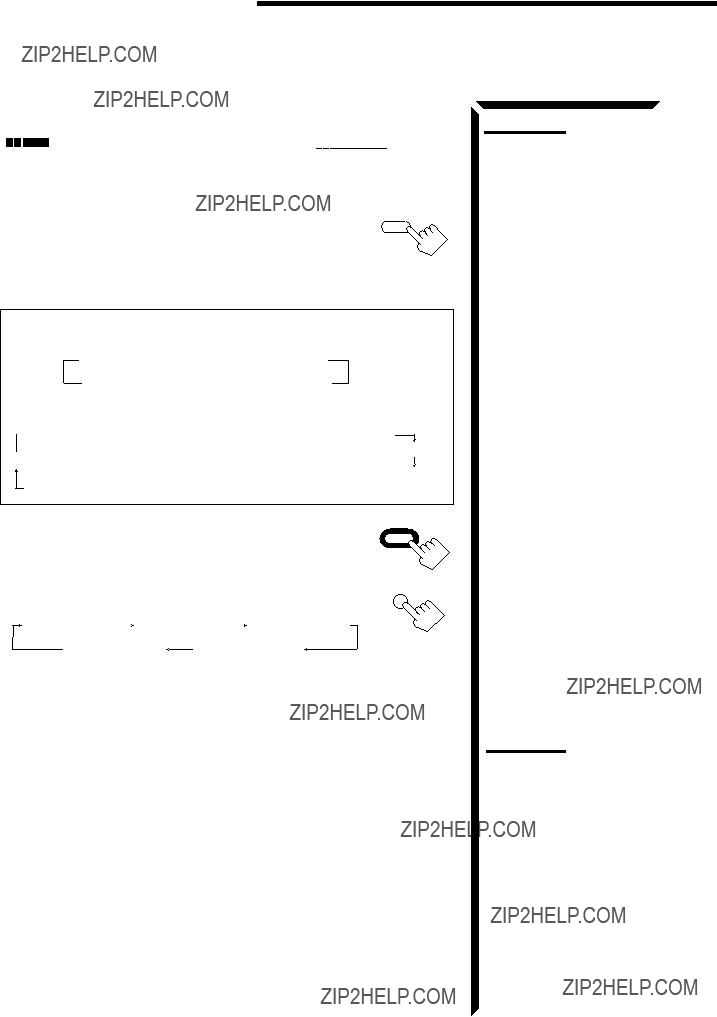
1.Press BALANCE/SURROUND ADJUST repeatedly until ???SUBWFR LEVEL??? appears on the display.
The display changes to show the current setting.
2.Turn MULTI JOG to adjust the subwoofer output level (??? 10 dB to +10 dB), while the indication of the previous step is still on the display.
From the remote control:
1.Press SOUND.
10 keys are activated for sound adjustments.
BALANCE/SURROUND
ADJUST
MULTI JOG
SOUND
??? SUBWOOFER +
2.Press SUBWOOFER +/??? to adjust the subwoofer output level (???10 dB to +10 dB).
Recording a Source
You can record any source playing through the receiver to the cassette deck or the MD recorder connected to the TAPE/MD jacks and the VCRs connected to the VCR1 and VCR2 jacks at the same time.
While recording, you can listen to the selected sound source at whatever sound level you like, without affecting the sound levels of the recording.
Note:
The output volume level and SEA modes cannot affect the recording.
IMPORTANT:
When recording the digital source, turn off the DSP mode.
16
Adjusting the Front Speaker Output Balance
If the sounds you hear from the front right and left speakers are unequal, you can adjust the speaker output balance.
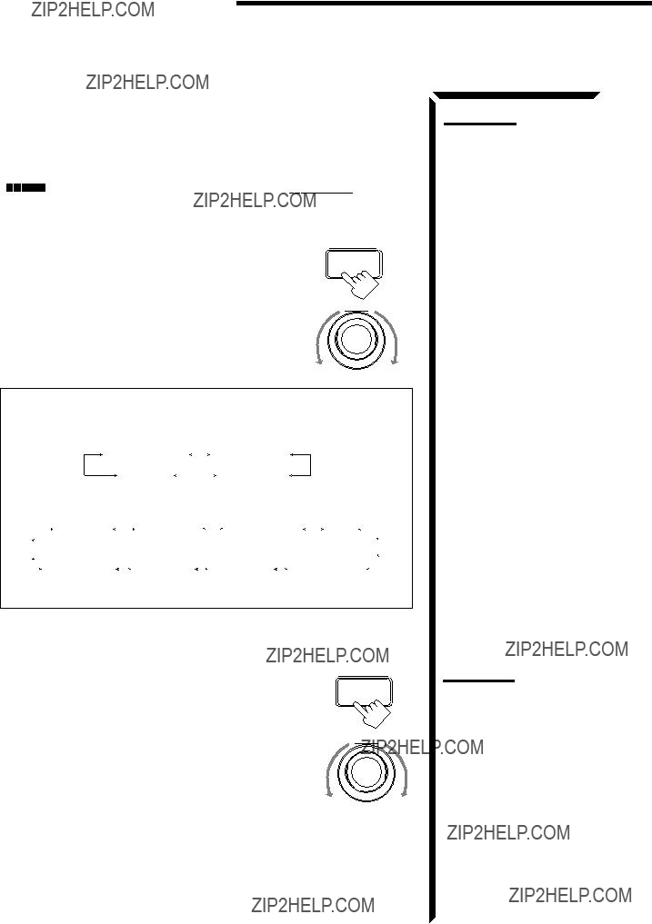
1.Press BALANCE/SURROUND ADJUST repeatedly until ???L/R BALANCE??? appears on the display.
The display changes to show the current setting.
MULTI JOG
2.Turn MULTI JOG to adjust the balance, while the indication of the previous step is still on the display.
???Turning it clockwise decreases the left channel output.
???Turning it counterclockwise decreases the right channel output.
Setting the Subwoofer Information
Register whether or not you have connected a subwoofer.
On the front panel only:
1.Press SETTING repeatedly until ???SUBWOOFER??? appears on the display.
The display changes to show the current setting.
2.Turn MULTI JOG to register whether you have connected a subwoofer or not, while the indication of the previous step is still on the display.
As you turn it, the subwoofer setting alternates between ???YES??? and ???NO.???
YES Select this when you use a subwoofer.
Listening at Low Volume (Loudness)
Human ears are not sensitive to bass at low volume. To compensate for this, the loudness function automatically boosts the bass level as you lower the volume.
Note:
The loudness function affects the front speaker sounds only.
On the front panel only:
Press LOUDNESS/SOURCE NAME briefly to select the loudness function.
Each time you press the button, the loudness function turns on (???LOUDNESS ON???) and off (???LOUDNESS OFF???).
???Select ???LOUDNESS ON??? to activate the loudness function. The LOUDNESS indicator lights up on the display.
???Select ???LOUDNESS OFF??? to cancel it.
The indicator goes off.
Receiving Radio Broadcasts
Assigning Names to Preset Stations
You can assign a name of up to four characters to each preset station. When a preset station is tuned in, its assigned name will appear on the display.
On the front panel only:
1.Tune in a preset station.
See page 24 for details.
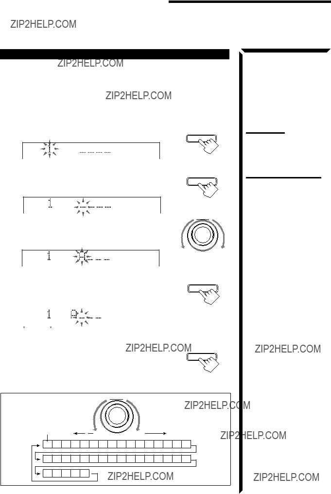
2.Press TUNER/SEA MEMORY.
The preset channel number starts flashing for about 5 seconds.
CH???
Note:
If you turn MULTI JOG while the preset channel number is flashing, you can change
the preset channel number.
3.Press TUNER PRESET, while the preset channel number is flashing.
The first character position starts flashing.
CH???
VOLUME
4.Turn MULTI JOG to select the first character, while the first character position is flashing..
You can use characters listed below.
CH???
VOLUME
Note on step 3 to 7:
You cannot select any entry after the indication on the display stops flashing.
In this case, repeat the procedure from step 2 again.
The next (or previous) character position starts flashing.
character is flashing after you have assigned a name.
To erase the input characters
Insert spaces using the same procedure described above.
MULTI JOG
Available characters

 Using the SEA Modes
The SEA (Sound Effect Amplifier) modes give you control of the way your music sounds.
Selecting Your Favorite SEA Mode
On the front panel:
1.Press SEA MODE.
The display changes to show the current setting.
2.Turn MULTI JOG until the mode you want appears on the display, while the indication of the previous step is still on the display.
As you turn it, the SEA mode changes as follows:
 SEA ROCK
 SEA MUSICAL
 SEA MOVIE
  SEA COUNTRY
SEA OFF
 SEA USERMODE
 SEA JAZZ
Notes:
???The SEA modes cannot be used for recording.
???When the SEA mode is turned on, the SEA indicator lights up on the display.
???When the SEA mode is used with the DAP mode (see page 32), sounds may be distorted. If this happens, turn off the DAP mode or decrease the effect level of the DAP mode.
To cancel the SEA mode
Turn MULTI JOG until ???SEA OFF??? appears in step 2 above.
The SEA indicator goes off from the display.
From the remote control:
1.Press SOUND.
10 keys are activated for sound adjustments.
2.Press SEA MODE repeatedly until the SEA mode you want appears on the display.
Each time you press the button, the SEA mode changes as follows:
 SEA ROCK
 SEA MUSICAL
 SEA MOVIE
  SEA COUNTRY
SEA OFF SEA USERMODE
  SEA JAZZ
To cancel the SEA mode
Press SEA MODE until ???SEA OFF??? appears in step 2 above. The SEA indicator goes off from the display.
Note:
When the SEA mode is turned on, the SEA indicator lights up on the display.
Using the SEA Modes
Creating Your Own SEA Mode
You can adjust and store your own SEA adjustment into memory (SEA USERMODE).
On the front panel only:
If you do not want to store your adjustment, but rather want to adjust the SEA temporarily, skip step 4 below.
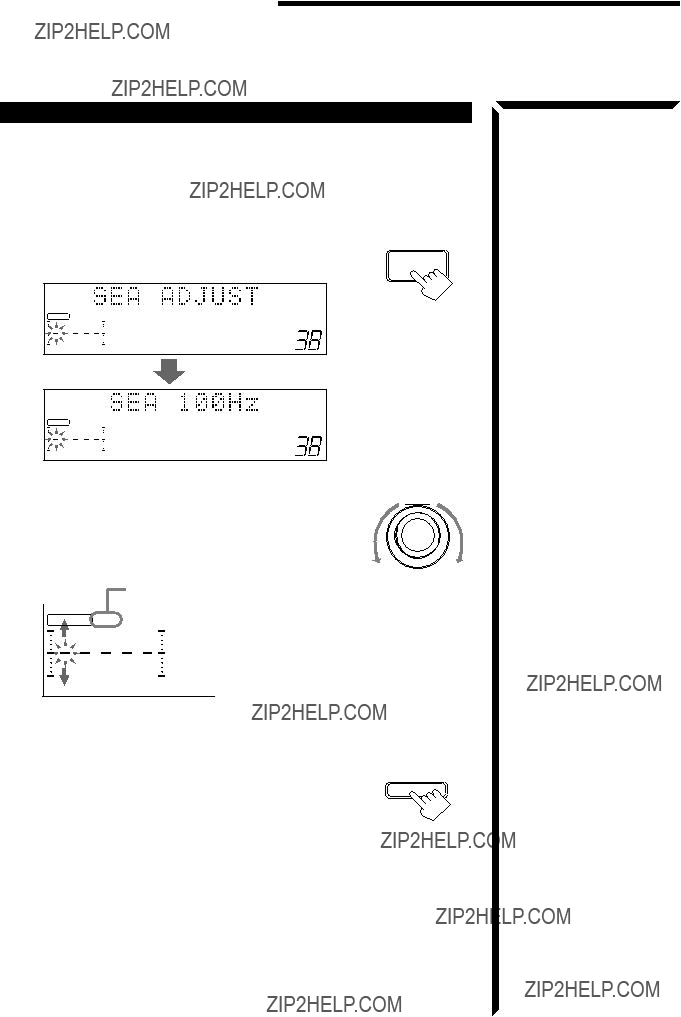
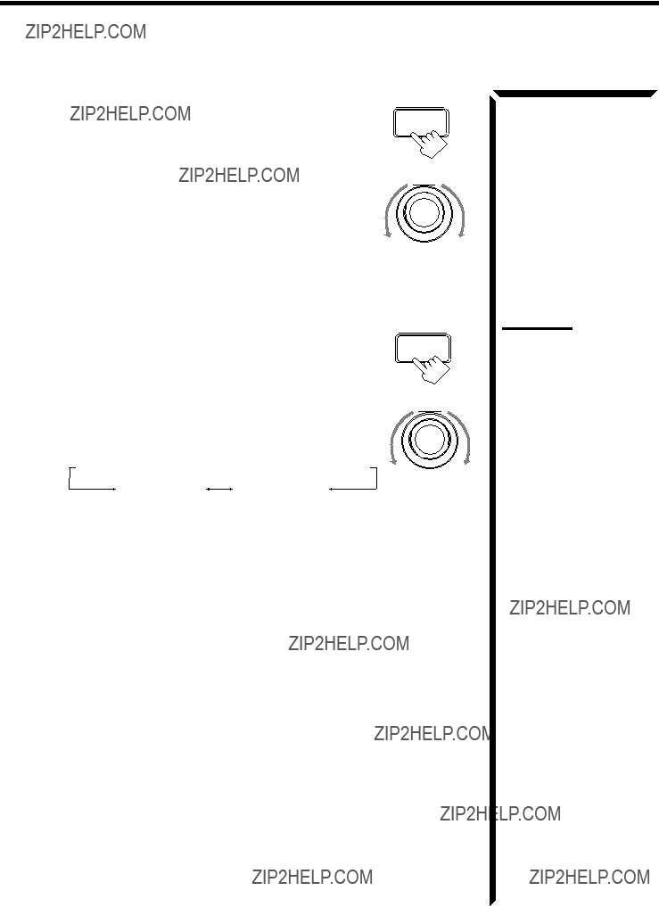
1.Press SEA ADJUST repeatedly until the frequency range (100Hz, 1kHz or 10kHz) you want appears on the display.
S E A FR
VOLUME
100 1k 10k
S E A FR
VOLUME
100 1k 10k
2.Turn MULTI JOG to adjust the SEA level of the selected frequency range, while the indication of the previous step is still on the display.
???Turning it clockwise increases the level.
???Turning it counterclockwise decreases the level.
This FR means this adjustment can be applied to the front speakers only
S E A FR
3.Repeat step 1 and 2 to adjust other frequency ranges if necessary.
4.Press TUNER/SEA MEMORY, while the indication of the previous step is still on the display.
Your adjustment is stored into the SEA USERMODE.
To recall your own SEA adjustment
See page 26.
To erase a stored adjustment
Storing a new adjustment into SEA USERMODE erases the previously stored one.

C:Lights when the test tone comes out of the center speaker.
R: Lights when the test tone comes out of the right front speaker.
RS: Lights when the test tone comes out of the right rear speaker.
LS: Lights when the test tone comes out of the left rear speaker.
IMPORTANT:
???Output the test tone while playing back an audio source.
With the DVD digital input selected as the source, no test tone may come out while no signal is input to this receiver.
???Test tone comes out even while playing back a source encoded with Dolby Digital. In this case, the PRO LOGIC indicator lights up on the display.
???To adjust the center speaker level, press CNTR +/???.
???To adjust the left rear speaker level, press REAR???L +/???.
TEST
Notes:
???No test tone comes out of the center speakers when ???CENTER SPK??? is set to ???NONE??? (see page 19).
???No test tone comes out of the rear speakers when ???REAR SPK??? is set to ???NONE??? (see page 19).
???If the TV is turned on and the proper video input is selected on the TV, the test tone screen will appear on the TV.
Notes:
6.Press TEST again to stop the test tone.
7.Press CNTR TONE to select the center tone level you want.
The center tone adjustment affects the mid-frequency range, which the human voice is mostly made up of. Each time you press the button, the display changes to show the following:
Note:
The center tone cannot be adjusted when ???CENTER SPK??? is set to ???NONE??? (see page 19).

 SOFT2
SOFT2  SOFT1
SOFT1  FLAT
FLAT  SHARP1
  SHARP2
Adjusted levels are also shown on the equalizer display.
100 1k 10k
To make the dialogue clearer, select ???SHARP1??? (little) or ???SHARP2??? (much). To make the dialogue softer, select ???SOFT1??? (little) or ???SOFT2??? (much). When ???FLAT??? is selected, no adjustment is applied.
To cancel the Surround mode
Press SURROUND MODE repeatedly until ???OFF??? appears.
5.Press BALANCE/SURROUND ADJUST repeatedly until ???CENTER TONE??? appears on the display.
The display changes to show the current setting.
6.Turn MULTI JOG to select the center tone level you want, while the indication of the previous step is still on the display.
The center tone adjustment affects the mid-frequency range, which the human voice is mostly made up of. As you turn it, the display changes to show the following:
BALANCE/SURROUND
ADJUST
MULTI JOG
 DSP EFFECT 1
 DSP EFFECT 2
 DSP EFFECT 3
As the number increases, the surround effect becomes stronger.
To cancel the Theater Surround mode
Turn MULTI JOG until ???DSP OFF??? appears in step 3.
The DSP and THEATER indicators goes off.
40

 Using the On-Screen Menus
You can use the menus on the TV screen to control the receiver.
To use this function, you need to connect the TV to the MONITOR OUT jack on the rear panel (see page 9), and set the TV???s input mode to the proper position to which the receiver is connected.

 Selecting the Source to Play (Also see page 13)
1.Press any button of ON SCREEN CONTROL %/ ???/ @/ #once.
The MAIN MENU appears on the TV.
Note
The on-screen display will disappear if no operation is done for about one minute.
MAIN MENU
 SOURCE :ch 1 FM 87.5 MHz??? VISUAL :VCR1???
MODE :OFF???
???
MAIN MENU
Shows the buttons you can use on the current menu.
In this case, use % / ??? to move  up and down, and @/ # to select, adjust or set the item.
2.Press ON SCREEN CONTROL %/ ???to move  to ???SOURCE.???
3.Press ON SCREEN CONTROL @/ #to select the source.
4.When you finish, press EXIT.
The menu disappears from the TV.

 Selecting the Different Sources for Picture and Sound
You can view the pictures played back on a video component while listening to any source.
1.Press any button of ON SCREEN CONTROL %/ ???/ @/ #once.
The MAIN MENU appears on the TV.
2.Press ON SCREEN CONTROL %/ ???to move  to ???VISUAL.???
3.Press ON SCREEN CONTROL @/ #to select a different video source.
??? When you select ???OSD,??? see page 49.
4.When you finish, press EXIT.
The menu disappears from the TV.
Using the DSP Modes (Also see pages 29, 32, 34, 37)
1.Press any button of ON SCREEN CONTROL %/ ???/ @/ #once.
The MAIN MENU appears on the TV.
2.Press ON SCREEN CONTROL %/ ???to move  to ???MODE.???
3.Press ON SCREEN CONTROL @/ #to select the DSP mode you want to use.
4.When you finish, press EXIT.
The menu disappears from the TV.

 TEXT COMPU LINK Remote Control System
The TEXT COMPU LINK remote control system has been newly developed to deal with the disc information recorded in the CD Text* and MDs. Using these information in the discs, you can operate the CD player or MD recorder equipped with the TEXT COMPU LINK remote control system through the receiver.
CONNECTIONS:
To use this remote control system, you need to connect the CD player and/or MD recorder you want to operate, following the procedures below.
1.If you have already plugged your CD player, MD recorder, and this receiver into the AC outlets, unplug their AC power cords first.
2.Connect your CD player, MD recorder, and this receiver as follows, through the COMPU LINK-3 (SYNCHRO) jacks and TEXT COMPU LINK jacks.
1)COMPU LINK-3 (SYNCHRO) jacks: Use the cables with the monaural mini- plugs (not supplied with this receiver)
COMPU LINK ??? 3 (SYNCHRO)
2)TEXT COMPU LINK jacks: Use the cables with the stereo mini-plugs (not supplied with this receiver)
IMPORTANT:
Set the Master/Slave Selector on the rear to ???1(MASTER UNIT).???
??? ???2(SLAVE UNIT)??? is just for the serviceman???s use. The TEXT COMPU LINK remote control system does not function with the selector set to ???2(SLAVE UNIT).???
3.Connect your CD player, MD recorder and this receiver, using the cables with RCA pin plugs (see page 8) (and a digital cable if you want ??? see page 11).
4.Plug the AC power cords of these components above into the AC outlets.
5.When turning on these components for the first time, turn on the connected components first, then turn on this receiver.
FUNCTIONS:
This remote control system allows you to use the functions listed below.
Displaying the Disc Information on the TV screen
Disc information such as its performer and disc title (and track titles only when a CD Text is selected) is shown on the TV screen.
Disc Search: Only for CD Player
This remote control system can allow you to search discs by the performer, disc title, and music genre.
With this disc search, you can easily find the disc you want to play.
Additional Functions:
???If your CD player has the User File function, you can select a disc from the groups.
*A ???user file??? is a group of the discs you make as you like on the CD player.
???If your CD player has the disc memory function, you can input the performer, disc title, and music genre about these normal audio CDs on the TV screen.
* What is a CD Text?
In a CD Text, some information about the disc (its disc title, performer, composer, arranger, etc.) is recorded.
Notes:
???If your audio component has two COMPU LINK-3 (SYNCHRO) jacks, you can use either one. If it has only one COMPU LINK-3 (SYNCHRO) jack, connect it so that it is the last item in the series of components. (For example, the CD player in the diagram to the left.)
???If your audio component has two TEXT COMPU LINK jacks, you can use either one. If it has only one TEXT COMPU LINK jack, connect it so that it is the last item in the series of components. (For example, the CD player in the diagram to the left.)
???Refer also to the manuals supplied with your CD player or MD recorder.
Note:
If you turn on the receiver before turning on the other components after connecting components, the TEXT COMPU LINK remote control system does not work correctly.
If this happens:
1.Turn off the all components including this receiver.
2.Turn on the connected components.
3.Turn on this receiver.

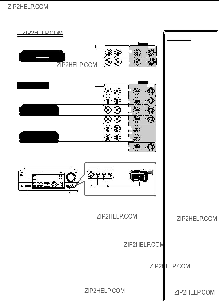
 AV COMPU LINK Remote Control System
The AV COMPU LINK remote control system allows you to operate JVC video components (TV, VCR, and DVD player) through the receiver.
CONNECTIONS:
To use this remote control system, you need to connect the video components you want to operate, following the procedures below.
1.If you have already plugged your VCR1 (the VCR connected to the VCR 1 jacks), DVD player, TV, and this receiver into the AC outlets, unplug their AC power cords first.
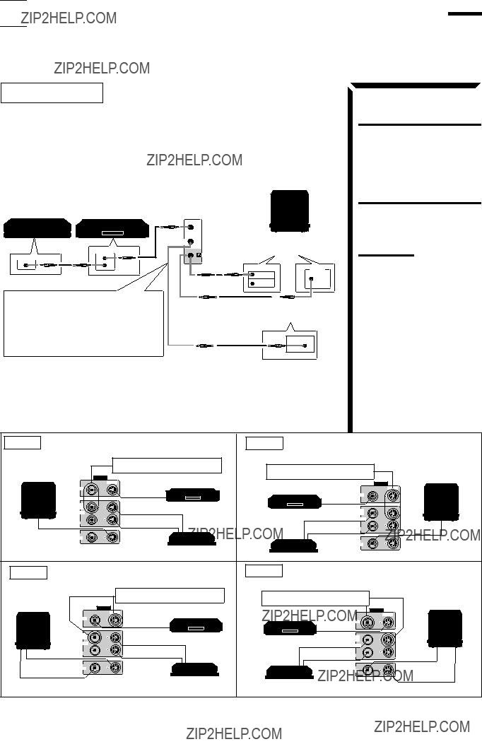
2.Connect your VCR1, DVD player, TV, and this receiver as follows, using the
CAUTION:
The AV COMPU LINK remote control system cannot control the DBS tuner connected to the TV/DBS jacks, and video components connected to the VIDEO and VCR2 jacks on the receiver.
Note:
When connecting either the VCR or DVD player to this receiver, connect it directly to the receiver using cable with the monaural mini-plugs.
3.Connect the audio input/output jacks on VCR1, DVD player, TV, and this receiver using the cables with RCA pin plug (see pages 9 to 10) (and a digital cable if you want ??? see page 11).
4.Connect the video input/output jacks on VCR1, DVD player, TV, and this receiver as follows, using the cables with RCA pin plug or with S-video plug.

 Operating JVC???s Audio/Video Components
You can operate JVC???s audio and video components with this receiver???s remote control, since control signals for JVC components are preset in the remote control.
IMPORTANT:
To operate JVC???s audio components using this remote control:
???You need to connect JVC audio components through the COMPU LINK-3 (SYNCHRO) jacks (see page 48) in addition to the connections using cables with RCA pin plugs (see page 8) or using digital cables (see page 11).
???Aim the remote control directly at the remote sensor on the receiver.
Tuner
After pressing FM or AM (with the remote control mode selector set to ???AUDIO/TV/VCR??? ), you can perform the following operations:
For channel number 5, press 5. For channel number 15, press +10, then 5. For channel number 20, press +10, then 10.
TUNING UP/TUNING DOWN:
Tunes into stations.
FM MODE/MUTE: Changes the FM reception mode.
Sound control section (Amplifier)
You can always perform the following operations (with the remote control mode selector set to ???AUDIO/TV/VCR??? ):
SURROUND MODE: Changes the DSP modes.
After pressing SOUND (with the remote control mode selector set to ???AUDIO/TV/VCR???) , you can perform the following operations:
CD player
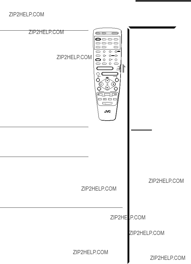
 LIGHT
LIGHT
RM-SR1024U REMOTE CONTROL
Note:
After adjusting sounds, press the corresponding source selecting button or DISC to operate your target source by using 10 keys; otherwise, 10 keys cannot be used for operating your target source.
After pressing CD (with the remote control mode selector set to ???AUDIO/TV/VCR??? ), you can perform the following operations on a CD player:
Starts playing.
Returns to the beginning of the current (or previous) track. Skips to the beginning of the next track.
Stops playing.
Pauses playing. To release it, press the PLAY button. Press this button with the PLAY button to start recording.
Press this button with the PAUSE button to enter recording pause.
Operating JVC???s Audio/Video Components
CD player-changer
After pressing DISC (with the remote control mode selector set to ???AUDIO/TV/VCR??? ), you can perform the following operations on the CD player-changer:
PLAY: Starts playing.
4: Returns to the beginning of the current (or previous) track.
??: Skips to the beginning of the next track.
STOP: Stops playing.
PAUSE: Pauses playing. To release it, press the PLAY button.
1 ??? 6, 7/P: Select the number of a disc installed in a CD player-changer.
After pressing CD (with the remote control mode selector set to ???AUDIO/TV/VCR??? ), you can perform the following operations on the CD player-changer:
1 ??? 10, +10: Selects a track number directly.
For track number 5, press 5. For track number 15, press +10, then 5. For track number 20, press +10, then 10. For track number 30, press +10, +10, then 10.
Turntable
After pressing PHONO (with the remote control mode selector set to ???AUDIO/TV/VCR??? ), you can perform the following operations on the turntable:
PLAY: Starts playing.
STOP: Stops playing.
Cassette deck
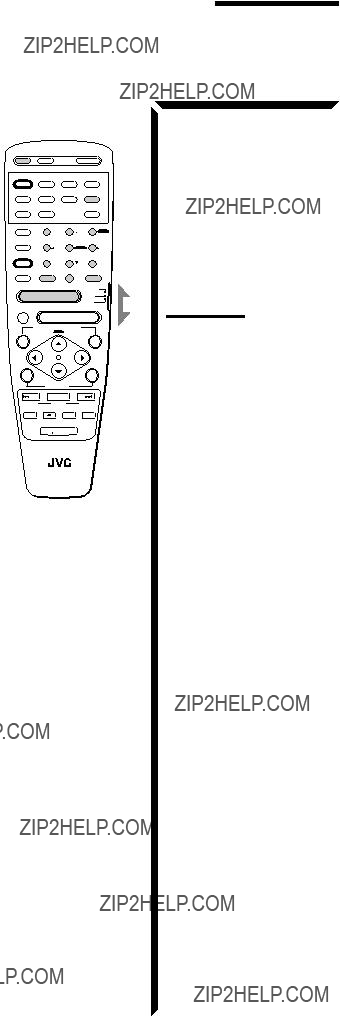
 LIGHT
LIGHT
RM-SR1024U REMOTE CONTROL
After pressing TAPE/MD or TAPE CONTROL (with the remote control mode selector set to ???AUDIO/TV/VCR??? ), you can perform the following operations on the cassette deck: PLAY: Starts playing.
REW: Fast winds the tape from right to left.
FF: Fast winds the tape from left to right.
STOP: Stops operations.
PAUSE: Pauses playing or recording temporarily. To release it, press the PLAY button.
REC ??: Press this button with the PLAY button to start recording.
Press this button with the PAUSE button to enter recording pause.
MD recorder
After pressing TAPE/MD or TAPE CONTROL (with the remote control mode selector set to ???AUDIO/TV/VCR??? ), you can perform the following operations on the MD recorder:
PLAY:
4: ??: STOP:
PAUSE: REC ??:
LIGHT
RM-SR1024U REMOTE CONTROL

 Operating Other Manufactures??? Components
This remote control supplied with the receiver can transmit control signals for other manufacturers??? VCRs, TVs, CATV converters and DBS tuners. By changing the transmittable signals from preset ones to the other manufacturers???, you can operate the other manufacturer???s components using this remote control.
When operating the other manufacturers??? components, refer also to the manuals supplied with them.
To operate these components with the remote control, first you need to set the manufacturer???s code each for the VCR, TV, CATV converter, and DBS tuner.
To operate a CATV converter, set it to ???CATV.???
To operate a DBS tuner, set it to ???DBS.???
To change the transmittable signals for operating another manufacturer???s TV
1.Set the remote control mode selector to ???AUDIO/TV/ VCR.???
2.Press and hold TV/CATV/DBS POWER.
3.Press TV/DBS.
4.Enter the manufacturer???s code (three digits) using buttons 1 ??? 9, and 0.
See the lists on page 65 to find the code.
5.Release TV/CATV/DBS POWER.
The following buttons can be used for operating the TV (with the remote control mode selector set to ???AUDIO/TV/ VCR??? ):
TV/CATV/DBS POWER: Turns on and off TV.
TV/VIDEO: Sets the input mode (either TV or
VIDEO).
Note:
Refer also to the manual supplied with your TV.
After pressing TV/DBS (with the remote control mode selector set to ???AUDIO/TV/VCR??? ), you can perform the
following operations on the TV:
CHANNEL +/???: Changes the channels.
1 ??? 10, 0, 100+(+10):Selects the TV channels.
100+(+10) button will function as the ENTER button if your TV requires pressing ENTER after selecting a channel number.
6.Try to operate your TV by pressing TV/CATV/DBS POWER.
When your TV turns on or off, you have entered the correct code.
7.If there are more than one code listed for your brand of TV, try each one until the correct one is entered.
When the TV is connected to the TV SOUND/DBS jacks on the rear:
The receiver automatically turns on and select ???TV SOUND??? as the source about 5 seconds after you turn on the TV. (If you change the source name from ???TV SOUND??? to ???DBS,??? the receiver will not turn on along with the TV. See page 17)
Note:
When you turn off the receiver with the TV kept turned on, the receiver will turn on soon again. To prevent this from happening, make sure that you turn off the TV before turning off the receiver.
Operating Other Manufactures??? Components
To change the transmittable signals for operating a CATV converter or DBS tuner
1.For the CATV converter:
Set the remote control mode selector to ???CATV.???
For the DBS tuner:
Set the remote control mode selector to ???DBS.???
2.Press and hold TV/CATV/DBS POWER.
3.Press TV/DBS.
4.Enter the manufacturer???s code (three digits) using buttons 1 ??? 9, and 0.
See the lists on page 66 to find the code.
5.Release TV/CATV/DBS POWER.
After setting the remote control mode selector to ???CATV??? or ???DBS,??? you can perform the following operations on the CATV converter or on the DBS tuner:
TV/CATV/DBS POWER: Turns on and off the CATV
6.Try to operate your CATV converter or DBS tuner by pressing TV/CATV/DBS POWER.
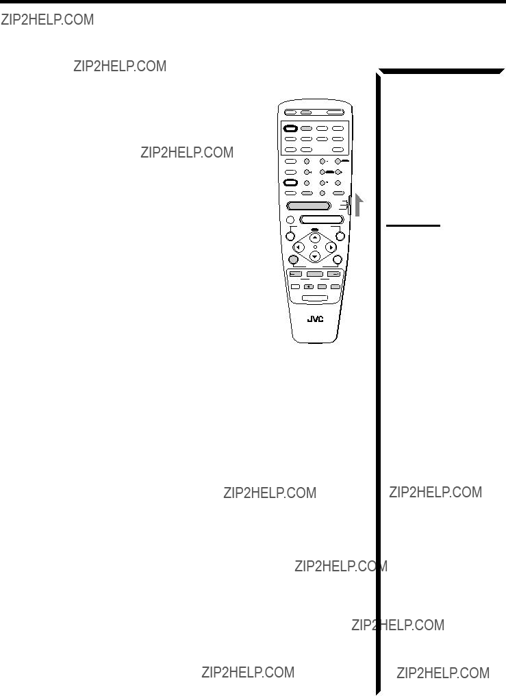
 LIGHT
LIGHT
RM-SR1024U REMOTE CONTROL
Note:
Refer also to the manual supplied with your CATV converter or DBS tuner.
When your CATV converter or DBS tuner turns on or off, you have entered the correct code.
7.If there are more than one code listed for your brand of CATV converter or DBS tuner, try each one until the correct one is entered.
To change the transmittable signals for operating another manufacturer???s VCR
1.Set the remote control mode selector to ???AUDIO/TV/ VCR.???
2.Press and hold VCR1 POWER.
3.Press VCR1.
4.Enter the manufacturer???s code (three digits) using buttons 1 ??? 9, and 0.
See the lists on pages 66 and 67 to find the code.
5.Release VCR1 POWER.
The following buttons can be used for operating the VCR (with the remote control mode selector set to ???AUDIO/TV/ VCR??? ):
VCR1 POWER: Turns on and off VCR.
After pressing VCR1 or VCR1 CONTROL (with the remote control mode selector set to ???AUDIO/TV/VCR??? ), you can perform the following operations on the VCR:
CHANNEL +/???: Changes the channels on the VCR.
1 ??? 10, 0, 100+(+10): Selects the channels on the VCR.
6. Try to operate your VCR by pressing VCR1 POWER.
REC
 LIGHT
LIGHT
RM-SR1024U REMOTE CONTROL
When your VCR turns on or off, you have entered the correct code.
7.If there are more than one code listed for your brand of VCR, try each one until the correct one is entered.

HOW TO LOCATE YOUR JVC SERVICE CENTER
TOLL FREE : 1-800-537-5722
Dear customer:
In order to receive the most satisfaction from your purchase, read the instruction booklet before operating the unit. In the event that repair is necessary, or for the address nearest your location, please refer to the factory service center list below or within the Continental United States, Call 1-800-537???5722 for your authorized servicer. Remember to retain you Bill of Sale for Warranty Service.
???JVC
JVC SERVICE & ENGINEERING
COMPANY OF AMERICA
DIVISION OF US JVC CORP.
FACTORY SERVICE CENTER LOCATIONS
Sophisticated electronic products may require occasional service. Just as quality is a keyword in the engineering and production of the wide array of JVC products, service is the key to maintaining the high level of performance for which JVC is world famous. The JVC service and engineering organization stands behind our products.
NATIONAL HEADQUARTERS
JVC SERVICE & ENGINEERING COMPANY OF AMERICA
DIVISION OF US JVC CORP.
107 Little Falls Road
Fairfield, NJ 07004-2105
If you ship the product ??? ??? ???
Pack your JVC unit in the original carton or one of equivalent size and strength. Enclose, with the unit, a letter stating the problem or symptom that exists and also a copy of the receipt or bill of sale you received when you purchased your JVC unit. Print your home return address on the outside and the inside of the carton. Send to the appropriate JVC Factory Service Center as listed above.
Don???t service it yourself.
CAUTION
To prevent electrical shock, do not open the cabinet. No user serviceable parts inside.
Refer servicing to qualified service personnel.
ACCESSORIES
To purchase accessories for your JVC product, you may contact your local JVC Dealer. Or from the 48 Continental United States call toll free : 800-882-2345
(0694)
LIMITED WARRANTY AUDIO-2
JVC COMPANY OF AMERICA warrants this product and all parts thereof, except as set forth below ONLY TO THE ORIGINAL PURCHASER AT RETAIL to be FREE FROM DEFECTIVE MATERIAL AND WORKMANSHIP from the date of original retail purchase for the period as shown below. (???The Warranty Period.???)
THIS LIMITED WARRANTY IS VALID ONLY IN THE FIFTY(50) UNITED STATES, THE DISTRICT OF COLUMBIA AND IN
COMMONWEALTH OF PUERTO RICO.
WHAT WE WILL DO:
If this product is found to be defective, JVC will repair or replace defective parts at no charge to the original owner. Such repair and replacement services shall be rendered by JVC during normal business hours at JVC authorized service centers. Parts used for replacement are warranted only for the remainder of the Warranty Period. All products and parts thereof may be brought to a JVC authorized service center on a carry-in basis except for Television sets having a screen size 25 inches and above which are covered on an in-home basis.
WHAT YOU MUST DO FOR WARRANTY SERVICE:
Return your product to a JVC authorized service center with a copy of your bill of sale. For your nearest JVC authorized service center, please call toll free: (800)537-5722.
If service is not available locally, box the product carefully, preferably in the original carton, and ship, insured, with a copy of your bill of sale plus and letter of explanation of the problem to the nearest JVC Factory Service Center, the name and location of which will be given to you by the toll-free number.
If you have any questions concerning your JVC Product, please contact our Customer Relations Department.
WHAT IS NOT COVERED:
This limited warranty provided by JVC does not cover:
1. Products which have been subject to abuse, accident, alteration, modification, tampering, negligence, misuse, faulty installation, lack of reasonable care, or if repaired or serviced by anyone other than a service facility authorized by JVC to render such service, or if affixed to any attachment not provided with the products, or if the model or serial number has been altered, tampered with, defaced or removed;
2. Initial installation and installation and removal for repair;
3. Operational adjustments covered in the Owner???s Manual, normal maintenance, video and audio head cleaning;
4.Damage that occurs in shipment, due to act of God, and cosmetic damage;
5.Signal reception problems and failures due to line power surge;
6. Video Pick-up Tubes/CCD Image Sensor, Cartridge, Stylus(Needle) are covered for 90 days from the date of purchase;
7. Accessories;
8. Batteries (except the Rechargeable Batteries are covered for 90 days from the date of purchase);
There are no express warranties except as listed above.
THE DURATION OF ANY IMPLIED WARRANTIES, INCLUDING THE IMPLIED WARRANTY OF MARCHANTABILITY, IS
LIMITED TO THE DURATION OF THE EXPRESS WARRANTY HEREIN.
JVC SHALL NOT BE LIABLE FOR THE LOSS OF USE THE PRODUCT, INCONVENIENCE, LOSS OR ANY OTHER
DAMAGES, WHETHER DIRECT, INCIDENTAL OR CONSEQUENTIAL (INCLUDING, WITHOUT LIMITATION, DAMAGE TO
TAPES, RECORDS OR DISCS) RESULTING FROM THE USE OF THIS PRODUCT, OR ARISING OUT OF ANY BREACH
OF THIS WARRANTY. ALL EXPRESS AND IMPLIED WARRANTIES, INCLUDING THE WARRANTIES OF
MERCHANTABILITY AND FITNESS FOR PARTICULAR PURPOSE, ARE LIMITED TO THE WARRANTY PERIOD SET
FORTH ABOVE.
Some states do not allow the exclusion of incidental or consequential damages or limitations on how long an implied warranty last, so these limitations or exclusions may not apply to you. This warranty gives you specific legal rights and you may also have other rights which vary from state to state.
REFURBISHED PRODUCTS CARRY A SEPARATE WARRANTY, THIS WARRANTY DOES NOT APPLY. FOR DETAILS OF
REFURBISHED PRODUCT WARRANTY, PLEASE REFER TO THE REFURBISHED PRODUCT WARRANTY INFORMATION
PACKAGED WITH EACH REFURBISHED PRODUCT.
For customer use:
Enter below the Model No. and Serial No. which is located either on the rear, bottom or side of the cabinet. Retain this information for future reference.
G-4


 Table of Contents


 Parts Identification
 LIGHT
LIGHT


 Basic Operations
 STANDBY
 CD
CD
 PHONO
PHONO
 TAPE/MD
 FM
FM
 AM
AM
 DVD
DVD
 VIDEO
VIDEO
 VCR2
VCR2
 VCR1
VCR1
 TV SOUND/DBS


 Basic Settings

 LARGE
LARGE
 SMALL
SMALL
 NONE
NONE 


 CROSS: 80Hz
 CROSS:100Hz
 CROSS:120Hz


 LFE ATT:10dB
 COMP.: OFF
 COMP.: MID
 COMP.: MAX


 One Touch Operation

 Receiving Radio Broadcasts


 Using the DSP Modes
 ) or with Dolby Surround (bearing the mark


 ).
). ) or with Dolby Surround (bearing the mark

 ), Theater Surround has been designed to create a real ???being there??? feeling.
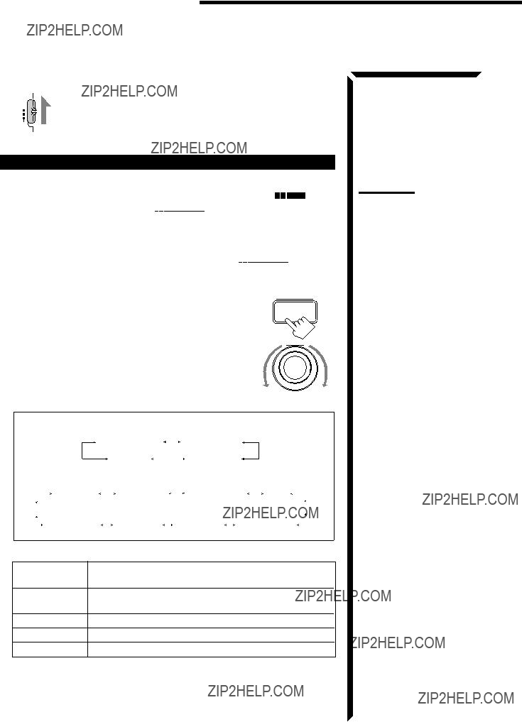


 ).
). ) or with Dolby Surround (bearing the mark

 ).
).
 DSP EFFECT 1
 DSP EFFECT 2
 DSP EFFECT 3


 ).
). DOLBY DIGITAL
  DIG-THEATER
 3D DIGITAL

 PRO LOGIC
  THEATER
  LIVE CLUB
  DANCE CLUB
 3D DRAMA
 3D ACTION


 DIG-THEATER


 3D DIGITAL

 DSP EFFECT 1
 DSP EFFECT 2
 DSP EFFECT 3


 LIVE CLUB
  DANCE CLUB
 3D DRAMA
 3D ACTION


 ).
). DOLBY DIGITAL
 3D DIGITAL
 HEADPHONE

 THEATER
  LIVE CLUB
  DANCE CLUB
 3D DRAMA
 3D ACTION
 HEADPHONE


 ).
).
 SOFT1
SOFT1 
 FLAT
FLAT
 SHARP1
 SHARP2


 ).
). 3D DIGITAL
 HEADPHONE
 PRO LOGIC
 LIVE CLUB
  DANCE CLUB
 3D DRAMA
 3D ACTION
 HEADPHONE


 SOFT2
SOFT2  SOFT1
SOFT1  FLAT
FLAT  SHARP1
  SHARP2


 ).
).

 SOFT1
SOFT1 
 FLAT
FLAT
 SHARP1


 Adjusting the Front Speaker Output Balance
  to ???SOUND CONTROL,??? then press
  to ???BAL.??? (Balance).
 Listening at Low Volume (Loudness)
  to ???SOUND CONTROL,??? then press
  to ???LOUDNESS.???
 Attenuating the Input Signal
  to ???SOUND CONTROL,??? then press
  to ???INPUT ATT.???
 :OPERATE
 LOUDNESS : OFF???
 :OPERATE
 INPUT ATT : NORMAL??? SUBWFR LEVEL: 0dB???
 :OPERATE

 Adjusting the Subwoofer Output Level
  to ???SOUND CONTROL,??? then press
  to ???SUBWFR LEVEL??? (Subwoofer Level).
 to ???MODE.???
 to ???SOUND CONTROL,??? then press
  to ???SURROUND LEVEL,??? then press
  to the item you want to set or adjust, then press ON SCREEN CONTROL
  SOURCE :ch 1 FM 87.5 MHz??? VISUAL :VCR1???
 :OPERATE

 Selecting Your Favorite SEA Mode
  to ???SOUND CONTROL,??? then press
  to ???SEA,??? then press
  to ???SEA MODE.???
 TEST TONE : OFF
 :OPERATE


 Creating Your Own SEA Mode
  to ???SOUND CONTROL,??? then press
  to ???SEA,??? then press
  to ???SEA ADJUST,??? then press
 Basic Settings
 to ???SETTING,??? then press
 to ???NEXT PAGE,??? then press
  to ???PREVIOUS PAGE,??? then press


 :ENTER
 :ENTER

 Operating the Tuner
 to ???TUNER CONTROL,??? then press
  to the item you want to set or adjust, then press ON SCREEN CONTROL
 Storing the Preset Stations
  to ???TUNER CONTROL,??? then press
  to ???PRESET MEMORY,??? then press
  to ???PRESET CH.???
 :OPERATE
 :OPERATE

 Assigning Names to the Preset Stations
  to ???TUNER CONTROL,??? then press
  to ???PRESET CH.???
 to ???PRESET MEMORY,??? then press
  to ???PRESET NAME,??? then press SET.
 in front of a character you want.
 : To go back to the previous character position or go to the next character position
 to ???PRESET
 COMPU LINK Remote Control System
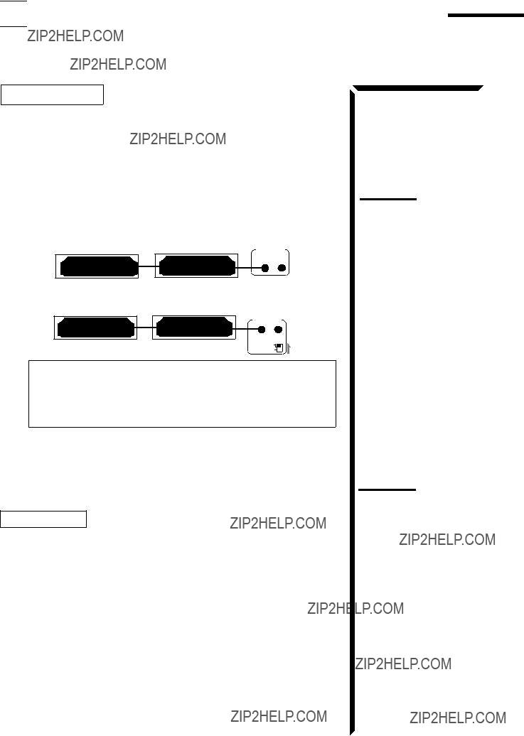


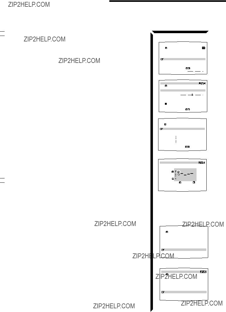
 Showing the Disc Information on the TV Screen
 to ???SOURCE.???
 to ???VISUAL.???
 to a track number, you can change the track information by pressing
  in front), then press SET to go to the DISC SEARCH screen (see page 51).
 in front), then press SET to go to the USER FILE screen (see page 53).
 in front), then press SET to go to the TITLE INPUT screen (see page 54).
 in front) , you can change the disc information by pressing
 or
or  , then press SET to change the track.
 in front)
 to ???VISUAL.???

 Searching a Disc (Only for the CD player)
 to ???SEARCH,??? then press SET.
 to ???PERFORMER???, then press SET.
 in front of the first character of the performer you want to search, then press SET.
 to ???CANCEL,??? then press SET.
 to a searched disc, then press
 to
to  (or
(or  ), then press SET.
 to ???SEARCH,??? then press SET.
 ???DISC TITLE???, then press SET.
 in front of the first character of the disc title you want to search, then press SET.
 to ???CANCEL,??? then press SET.
 ???
???


 ???
???

 to a searched disc, then press
 to
to  (or
(or  ), then press SET.
 to ???SEARCH,??? then press SET.
 to ???GENRE???, then press
 to the genre you want to search, then press SET.
 to a searched disc, then press
 to
to  (or
(or  ), then press SET.


 ???
??? 


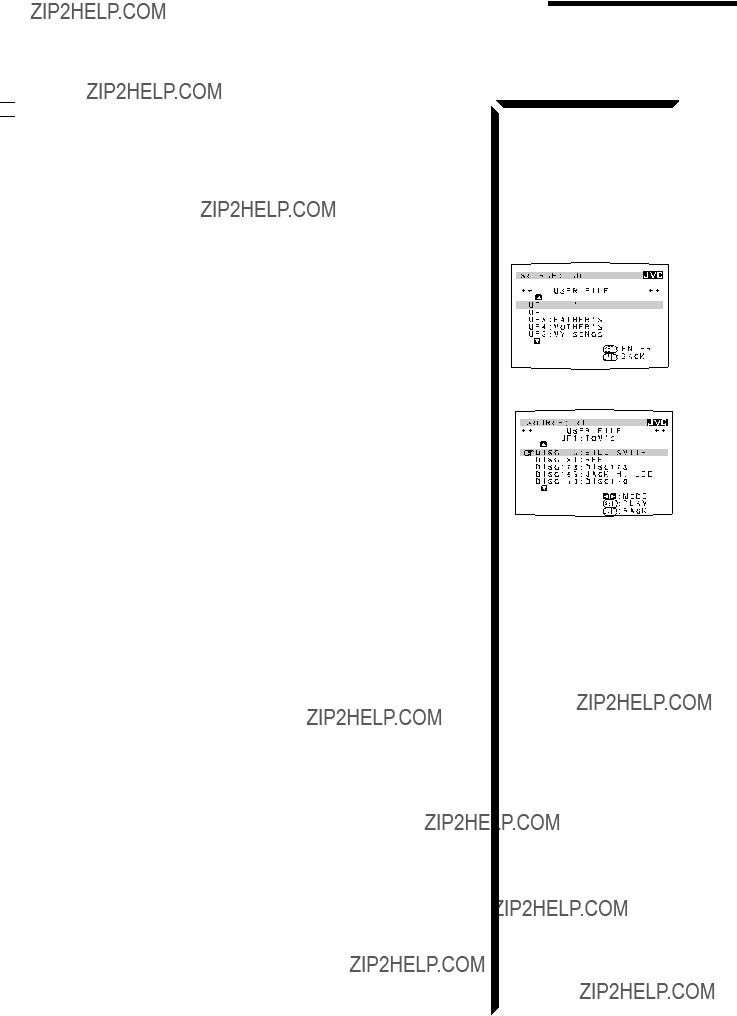

 Using the User File (Only for the CD Player with the User File Function)
 to ???USER FILE,??? then press SET.
 to the User File you want, then press SET.
 to a disc, then press SET.
 to
to  (or
(or  ) and press SET.


 Entering the Disc Information
 to ???TITLE INPUT,??? then press SET.
 in front of a character you want, then press SET to enter the character.
 to SPACE , then press SET.
 to
to  or
or  , then press SET until the incorrect character is selected.
 to CANCEL, then press SET to erase the character.
 in front of an correct character, then press SET to enter a correct character.
 to ???DISC1:


 to ???DISC1: MY
 to the genre you want, then press SET.
 to ???TITLE INPUT,??? then press SET.
 to the disc title you have just entered, then press SET.
 to the song title you have just entered, then press SET.
 ???
??? 


 LIGHT
LIGHT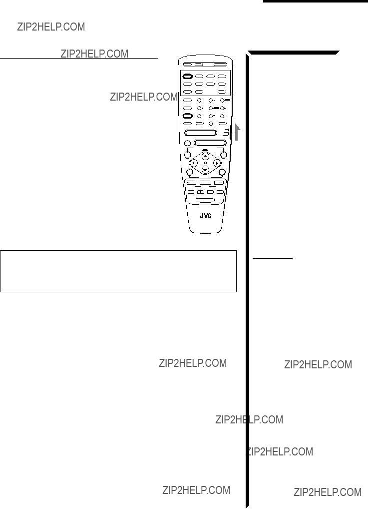
 LIGHT
LIGHT


 Troubleshooting

 Specifications

