Please visit our CyberCam Homepage on the World Wide Web and answer our Consumer Survey (in English only):
http://www.jvc-victor.co.jp/index-e.html
STILL CAMERA
For Customer Use:
Enter below the Model No. and Serial
No. which is located on the bottom of
INSTRUCTIONS cabinet. Retain this information for future reference.
Model No.
Serial No.
???After use, unplug the Power Cord from the AC outlet.
1 Connect the Power Cord to the AC Power Adapter.
???Make sure connections are secure.
2 Connect the DC Cord to the DC Input Connector of the Digital Still Camera.
3 Connect the Power Cord to an AC outlet.
NOTES:
cThe optional AA-V33 AC Power Adapter features automatic voltage selection in the AC range from 110 V to 240 V.
cMake sure the Power Cord is securely connected to the AC Power Adapter.
cWhen using the AC Power Adapter, use only the Power Cord provided with the AC Power Adapter. Use of any other cord may result in shock or fire.
cConnect the Power Cord to the AC Power Adapter before connecting it to an AC outlet. If you plug it into an outlet first, and the Adapter???s terminals come in contact with a metal surface or object, short circuit or fire may result.
cVibration noise can sometimes be heard coming from the inside of the AC Power Adapter. This is normal.
cThe AC Power Adapter processes electricity internally, and will become warm during use. This is normal. Make sure to use the AC Power Adapter in well-ventilated areas only.
ATTENTION:
Before detaching the power source, make sure that the camera???s power is turned off. Failure to do so may cause the camera???s built-in memory to be corrupted.
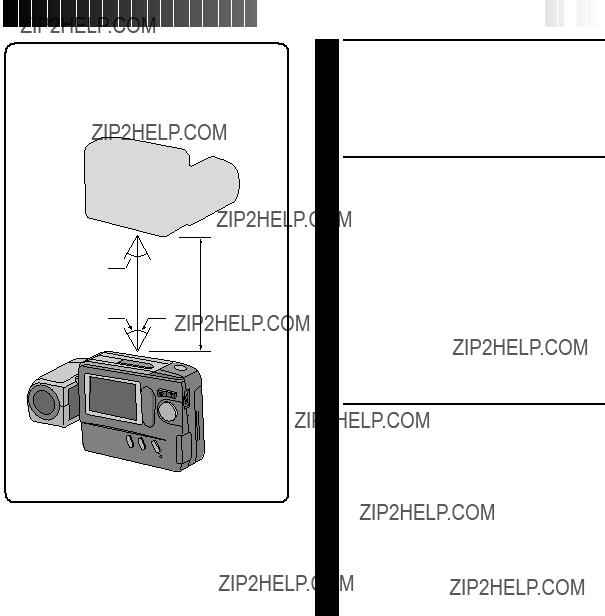
To obtain the most stable position for shooting while viewing the LCD monitor, hold the lens so that it forms an angle of 45 degrees in relation to the camera body.
The lens tilts up to 100 degrees forward and 90?? backward. You can photograph yourself, while viewing your own image on the LCD monitor (Self- Recording), by tilting the lens 90 degrees backward and taking your picture. This can be used for things such as keeping a photo diary.
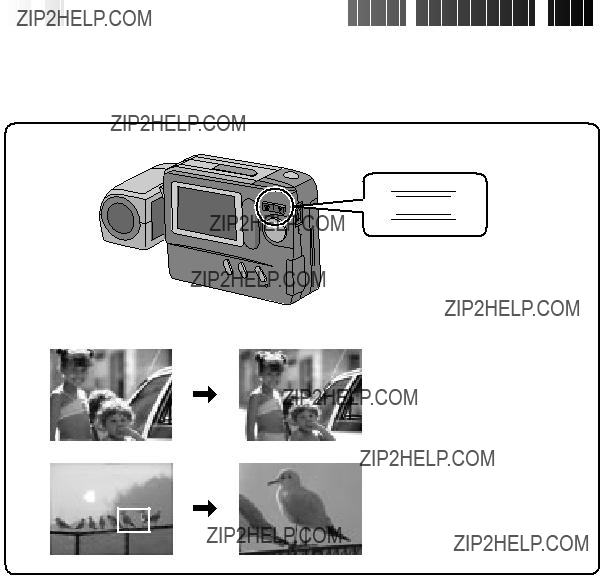
The Shutter Release Button of the camera has two steps. At the first step, when the button is pressed halfway, ??? ??? is displayed and the camera automatically focuses on the subject. ???
 ??? disappears once the subject has been brought into focus.
The operation of pressing the Shutter Release Button to the first step is called a ???half-press???. From the ???half-pressed??? position, press the button all the way to the second step.
Unpressed position
Half-pressed position
Fully-pressed position
cDo not press the Shutter Release Button with your finger raised over the button or do not press it with too strong a force, as this may disrupt the horizontal positioning of the image or cause blurring. When shooting, always half-press the button before pressing it fully to the second step.
cIf focusing is performed by pressing the Shutter Release Button frequently during auto focus, the period between when the Shutter Release Button is pressed and when the shutter is released will be shortened.
cWhile the camera is performing auto focusing with the button half-pressed, the displayed image may freeze temporarily. This is not a malfunction.
cWhen the Shutter Release Button is released from the half-pressed position and half-pressed again, the camera performs auto focusing again.
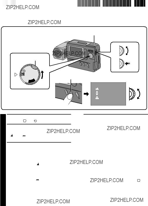
Shooting Mode Selection
Turning the Power Dial allows you to select the appropriate shooting mode from among the following:
 OFF
OFF  YA
YA
??? : Full Auto mode
The camera will automatically control all items including exposure, shutter speed, focusing and white balance.
??? : Manual mode
Exposure, shutter speed, focusing and white balance can be controlled manually according to the shooting conditions.
??? ??? : Self-Timer mode
A 15-second self-timer can be used.
Simple Shooting (Full Auto Shooting)
In the Full Auto mode, the camera controls focusing, shutter speed, exposure and white balance automati- cally to make your shooting simple and easy.
Shutter Release Button
Power Dial
Lock Button
 OFF
OFF  YA
YA
??? The camera turns on in the Full Auto mode.
2 Train the lens on the subject to be photo- graphed.
???If the low light ???
 ??? icon appears on the LCD monitor, use the flash (Z pg. 22).
3 Press the Shutter Release Button.
??? The image will be stored in the built-in memory or Compact Flash card.
NOTES:
cWhen the Shutter Release Button is half-pressed, auto focusing is performed.
cAfter storing images in the built-in memory, it is recommended that you transfer them to a Compact Flash card or PC.
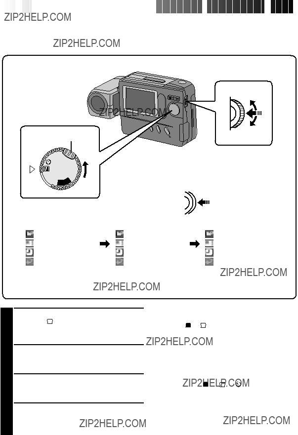
DISPLAY Button
Standard View mode (color display)
LCD monitor
Standard View with Information Display mode
Standard View with Information Display mode (color display)
cEach press of the DISPLAY Button switches the View mode. The camera setup can be checked in the Information Display Screen.
Zoom Shooting
The camera incorporates a 10X zooming function that corresponds to a 43 mm to 430 mm lens of a 35 mm camera. Zooming allows you to shoot wide areas, as well as close-ups of subjects located far away, without changing the shooting position.


 W
W 
 T
T 


W (Wide-angle) zooming
A relatively wide area can be photographed.
T (Telescopic) zooming
A faraway subject can be magnified and photographed.
NOTE:
Use the flash when the low light ???
 ??? icon appears.
Power Dial
Lock button
LCD monitor
Jog Dial.
???The CAMERA MENU Screen appears.
2 Rotate the MENU Jog Dial to select ???CAMERA??? and push it.
???The CAMERA Setup Screen appears.
3 Rotate the MENU Jog Dial to select ???EXPOSURE??? and push it.
???The EXPOSURE Setup Screen appears.
4 Rotate the MENU Jog Dial to select the current value and push it.
???The item color changes to indicate that setting is possible.
5 Rotate the MENU Jog Dial to adjust the exposure.
???The exposure value can be selected from ???6 and +6.
To brighten the image:
Increase the exposure value. (maximum +6)
To darken the image:
Decrease the exposure value. (maximum ???6)
6 Push the MENU Jog Dial twice.
???The EXPOSURE Setup Screen disappears. ???The exposure value is set and the shooting
screen reappears.
To adjust a previously set exposure value . . .
.... repeat the above procedure from step 1.
To set the exposure value to the standard level, set the exposure value to ???0??? or turn the Power Dial to

 OFF
OFF
1 Turn the Power Dial, while pressing its Lock Button, to ??? M ??? or ??? ??? and push the MENU Jog Dial.
??? The CAMERA MENU Screen appears.
2 Rotate the MENU Jog Dial to select ???CAMERA??? and push it.
??? The CAMERA Setup Screen appears.
3 Rotate the MENU Jog Dial to select ???M.W.B.??? (Manual White Balance) and push it.
??? The M.W.B. Setup Screen appears.
NOTE:
If a satisfactory white balance cannot be obtained with any of the ??? ???, ???
 ???, ???
 ??? or ???AUTO??? positions, adjust the white balance manually as indicated in ???Adjusting the White Balance Manu- ally??? (Z pg. 25).
4 Rotate the MENU Jog Dial to select ??? ???, ???
 ???, ???
 ??? or ???AUTO??? and push it.
???Select the preset that can provide the subject with the most desirable white balance.
The following 5 options can be selected. AUTO ...... Select this position to adjust the
color balance automatically. When the Full Auto mode is selected with the Power Dial, this position is selected automatically.
 ............ Select for shooting outdoors on a fine day.
 ........... Select for shooting on a cloudy day or in the shade.
 ............. Select for shooting with in- candescent lamps or video lighting, etc.
MWB .......Select to photograph the subject with a previously adjusted color balance (Z pg. 25).
5 Push the MENU Jog Dial twice.
???The M.W.B. Setup Screen disappears and the shooting screen reappears.
Example:
When red paper is used:
The colors will be blue-greenish. When blue paper is used:
The colors will be amberish. When yellow paper is used:
The colors will be purplish.
NOTE:
The manually-set white balance is held in memory until another balance value is set by selecting ???M.W.B.???.
When the white balance is adjusted using colored paper . . .
.... in step 2, you can shoot images with a different color tone than when white paper is used.
???The M.W.B. Setup Screen disappears and the shooting screen reappears.
To return a manually-set white balance to an automatically-set white balance . . .
.... select ???AUTO??? in step 4 in the procedure on page 24 or turn the Power Dial to ??? A ???.
During indoor shooting . . .
.... the subject is exposed to a variety of light sources, including outdoor light, fluorescent light, candle light and so on. As the color temperatures of these light sources vary widely, manual white balance adjustment is recom- mended if you want to shoot images with the most natural color tones possible.
Rotate the MENU Jog Dial to select ???EXIT??? and push it 3 times.
4
Push the MENU Jog Dial.
???The setting is completed after about 1 second.
???The setting can be redone by pushing the MENU Jog Dial again.
3
EN 25
Adjusting the White Balance Manually (M.W.B.)
If none of the preset ??? ???, ??? ???, ??? ??? or ???AUTO??? positions can make the colors in the image look natural, adjust the white balance manually to obtain the most suitable color tones possible.
1 In step 4 on the previous page (Z pg. 24), select ???MWB???.
2 Place a sheet of white paper about 1 ft. (30 cm) in front of the lens.
???Place it so that the white paper fills the
screen.
Playback Through a TV Monitor or VCR
By connecting the digital still camera to a TV monitor or VCR and starting playback, images can be monitored on the TV screen or recorded onto a videotape.
TV
VCR
NOTES:
cFor connections to a TV monitor or VCR, refer to their instruction manuals.
cThe playback image can also be viewed on the LCD monitor of the camera without connecting it to a TV monitor or VCR.
cDuring playback on a TV monitor, indications displayed in any of the shooting modes do not appear.
???The PLAY MODE Screen appears.
Rotate the MENU Jog Dial to select ???EFFECT??? and push it.
???The EFFECT Setup Screen appears.
Rotate the MENU Jog Dial to select ???ZOOM??? and push it.
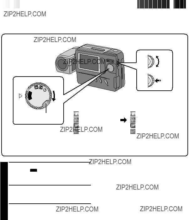
Dial.
???The PLAY MENU Screen appears.
2 Rotate the MENU Jog Dial to select ???PLAY MODE??? and push it.
3
4
5 Rotate the MENU Jog Dial to select the area to be magnified, and push it.
???The selected image is split into 9 areas, from which you can select the area to be magni- fied. By rotating the MENU Jog Dial, you can reach the desired area as indicated above.
???The effect is applied to other displayed images until it is canceled.
To cancel the effect . . .
.... press the CLEAR Button.


 EN
EN 47
47

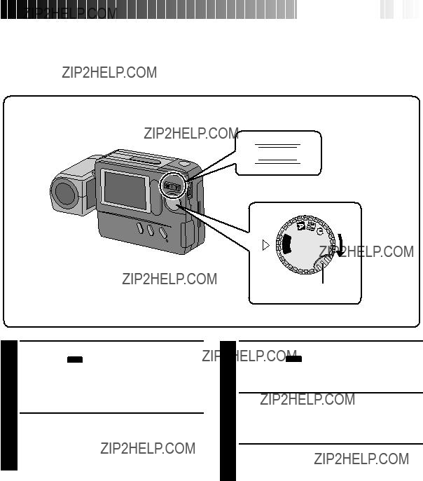
Initializing the Storage Media
Since the camera is a microcomputer-controlled device, external noise and interference (from a TV, a radio, etc.) might prevent it from functioning properly. For example, when a still image you shot is stored in memory, the above may cause the following: Although the remaining number of shots indicator shows that shooting is possible, a still image cannot be stored in memory after shooting.
In such a case, initialize the memory by following steps 1 through 4 below. Please note that initialization deletes all the still images (including ones for which you performed the ???Protect??? function) stored in memory. If you wish to keep any of the still images that are stored in memory, before initialization first transfer them to a PC and save them. If image data is corrupt, transfer is impossible. Normally, it is not necessary to initialize a Compact Flash card. However, if a malfunction occurs (for example, if the image you shot cannot be played back), then initialize the Compact Flash card.
NOTE:
Switch the camera off with the Power Dial before installing a Compact Flash card.
Preparation
Insert the Compact Flash card to be initialized.
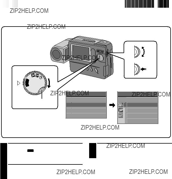
Dial.
???The PLAY MENU Screen appears.
PLAY MENU Screen
PLAY MENU

 PLAY MODE

 F I LE

 COMM . MODE

 EX I T
F I LE


 PROTECT
DELETE
COPY
FORMAT
EX I T
Power Dial
 OFFY
OFFY
A
L
 P
P
Lock Button
MENU Jog Dial
FILE Screen
2 Rotate the MENU Jog Dial to select ???FILE??? and push it.
???The FILE Screen appears.
3 Rotate the MENU Jog Dial to select ???FORMAT??? and push it.
4 Rotate the MENU Jog Dial to select ???EXECUTE??? and push it.
???The message ???FORMATTING IN PROGRESS??? is displayed and formatting starts.
???When ???NO IMAGES STORED??? is displayed, formatting is complete.
CAUTION
without the preset frames.
cAfter initializing, all images stored in the compact flash card, including those which have been protected, are cleared. Be sure to transfer important images to a PC before proceeding with initialization. However, if image data is corrupt, it cannot be transferred to a PC.
cInitializing a Compact Flash card does not clear images stored in the camera???s built-in memory.
cIf the message ???PLEASE INITIALIZE??? appears, the built-in memory needs to be initialized. Without inserting a Compact Flash card, perform steps 1 through 4.
cWhen a Compact Flash card is not installed, ???FORMAT??? normally cannot be selected. If it can be selected, then the built-in memory is malfunctioning. When this occurs, make a back-up of the stored image data before initializing.
1 Install the Compact Flash card in the camera.
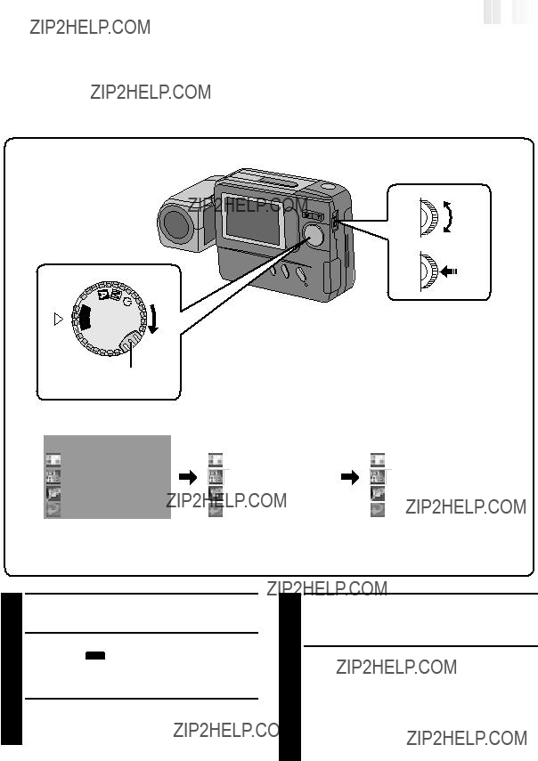
Dial.
???The PLAY MENU screen appears.
3 Rotate the MENU Jog Dial to select ???FILE??? and push it.
???The FILE Screen appears.
4 Rotate the MENU Jog Dial to select ???COPY??? and push it.
???The COPY Screen appears.
5 Rotate the MENU Jog Dial to select ???CAMERA ??CARD??? or ???CARD ??CAMERA??? and push the MENU Jog Dial.
???The COPY Setup Screen appears.
To copy selected images only . . .
Go to step 6 on page 50.
To copy all images . . .
Go to step 6 on page 51.
Power Dial
 OFFY
OFFY
A
L
 P
P
MENU Jog Dial
FLASH/TRANSFER Button
1 Turn the Power Dial, while pressing its Lock Button, to ??? PLAY ??? and push the MENU Jog Dial.
??? The PLAY MENU Screen appears.
2 Rotate the MENU Jog Dial to select ???COMM. MODE??? and push it.
??? The COMM. MODE Setup Screen appears.
3 Rotate the MENU Jog Dial to select ???IR MODE??? and push it twice.
???The normal playback screen reappears.
ACCESSORIES
To purchase accessories for your JVC product, you may contact your local JVC Dealer.
Or from the 48 Continental United States call toll free: 1-800-882-2345.
Don't service it yourself.
CAUTION
To prevent electrical shock, do not open the cabinet. No user serviceable parts inside. Refer servicing to qualified service personnel.
 WARRANTY
 (Only
(Only

 in
in
 U.S.A.)


 EN
EN 71
71

JVC COMPANY OF AMERICA warrants this product and all parts thereof, except as set forth below ONLY TO THE ORIGINAL PURCHASER AT RETAIL to be FREE FROM DEFECTIVE MATERIALS AND WORKMANSHIP from the date of original retail purchase for the period as shown below. ("The Warranty Period")
THIS LIMITED WARRANTY IS VALID ONLY IN THE FIFTY (50) UNITED STATES, THE DISTRICT OF
COLUMBIA AND IN COMMONWEALTH OF PUERTO RICO.
WHAT WE WILL DO:
If this product is found to be defective, JVC will repair or replace defective parts at no charge to the original owner. Such repair and replacement services shall be rendered by JVC during normal business hours at JVC authorized service centers. Parts used for replacement are warranted only for the remainder of the Warranty Period. All products and parts thereof may be brought to a JVC authorized service center on a carry-in basis except for Television sets having a screen size 25 inches and above which are covered on an in-home basis.
WHAT YOU MUST DO FOR WARRANTY SERVICE:
Return your product to a JVC authorized service center with a copy of your bill of sale. For your nearest JVC authorized service center, please call toll free: (800) 252-5722.
If service is not available locally, box the product carefully, preferably in the original carton, and ship, insured, with a copy of your bill of sale plus a letter of explanation of the problem to the nearest JVC Factory Service Center, the name and location of which will be given to you by the toll-free number.
If you have any questions concerning your JVC Product, please contact our Customer Relations Department.
WHAT IS NOT COVERED:
This limited warranty provided by JVC does not cover:
1.Products which have been subject to abuse, accident, alteration, modification, tampering, negligence, misuse, faulty installation, lack of reasonable care, or if repaired or serviced by anyone other than a service facility authorized by JVC to render such service, or if affixed to any attachment not provided with the products, or if the model or serial number has been altered, tampered with, defaced or removed;
2.Initial installation and installation and removal for repair;
3.Operational adjustments covered in the Owner's Manual, normal maintenance, video and audio head cleaning;
4.Damage that occurs in shipment, due to act of God, and cosmetic damage;
5.Signal reception problems and failures due to line power surge;
6.Video Pick-up Tubes/CCD Image Sensor, Cartridge, Stylus (Needle) are covered for 90 days from the date of purchase;
7.Accessories;
8.Batteries (except that Rechargeable Batteries are covered for 90 days from the date of purchase);from the date of purchase);
There are no other express warranties except as listed above.
THE DURATION OF ANY IMPLIED WARRANTIES INCLUDING THE IMPLIED WARRANTY OF
MERCHANTABILITY, IS LIMITED TO THE DURATION OF THE EXPRESS WARRANTY HEREIN.
JVC SHALL NOT BE LIABLE FOR THE LOSS OF USE OF THE PRODUCT, INCONVENIENCE, LOSS OR ANY
OTHER DAMAGES, WHETHER DIRECT, INCIDENTAL OR CONSEQUENTIAL (INCLUDING, WITHOUT
LIMITATION, DAMAGE TO TAPES, RECORDS OR DISCS) RESULTING FROM THE USE OF THIS PRODUCT,
OR ARISING OUT OF ANY BREACH OF THIS WARRANTY. ALL EXPRESS AND IMPLIED WARRANTIES,
INCLUDING THE WARRANTIES OF MERCHANTABILITY AND FITNESS FOR PARTICULAR PURPOSE, ARE
LIMITED TO THE WARRANTY PERIOD SET FORTH ABOVE.
Some states do not allow the exclusion of incidental or consequential damages or limitations on how long an implied warranty lasts, so these limitations or exclusions may not apply to you. This warranty gives you specific legal rights and you may also have other rights which vary from state to state.
REFURBISHED PRODUCTS CARRY A SEPARATE WARRANTY, THIS WARRANTY DOES NOT APPLY. FOR
DETAILS OF REFURBISHED PRODUCT WARRANTY, PLEASE REFER TO THE REFURBISHED PRODUCT
WARRANTY INFORMATION PACKAGED WITH EACH REFURBISHED PRODUCT.
For customer use:
Enter below the Model No. and Serial No. which is located either on the rear, bottom or side of the cabinet. Retain this information for future reference.


 EN
EN


 EN
EN


 EN
EN


 QUICK
QUICK
 START
START


 OFF
OFF YA
YA


 QUICK
QUICK
 START
START


 MAJOR
MAJOR
 FEATURES


 are trademarks of SanDisk Corporation, registered in the U.S.A. and other countries.


 EN
EN


 EN
EN


 GETTING
 STARTED


 OFF
OFF


 EN
EN


 EN
EN


 BASIC
BASIC OPERATION


 EN
EN


 CAMERA
 P I CTURE MODE
 SYSTEM
 EX I T

 F I NE


 BASIC
BASIC OPERATION


 EN
EN


 BASIC
BASIC OPERATION


 EN
EN


 OFF
OFF ???.
???. ??? appears.
 ??? icon appears on the LCD monitor, use the flash (
 ???.
???.


 BASIC
BASIC OPERATION


 ??? icon appears
  OFF
OFF 
 ??? icon appears on the LCD monitor.


 EN
EN


 To darken the image
 To brighten the image


 MANUAL
 SHOOTING


 ???, ???
 ??? or ???
 ???), select the one that makes the colors in the image look the most natural. If the colors appear only slightly unnatural, select ???AUTO???.


 MANUAL
 SHOOTING


 OFF
OFF ??? and push the MENU Jog Dial.


 MANUAL
 SHOOTING


 OFF
OFF ??? appear, and the focus can be adjusted manually.
 ??? starts to blink.
 ??? and ???
 ??? disappear.


 EN
EN


 OFF
OFF 


 MANUAL
 SHOOTING


 OFF
OFF ??? and push the MENU Jog Dial.
 ??? or ???


 EN
EN


 OFF
OFF


 PLAYBACK


 EN
EN


 W
W 
 T
T 


 OFF
OFF P
P


 PLAYBACK


 : Protect icon


 EN
EN


 PLAYBACK


 OFF
OFF P
P


 EN
EN


 PLAYBACK


 OFF
OFF P
P
 PLAY MODE
 F I LE
 COMM . MODE
 EX I T

 PROTECT


 PLAYBACK


 EN
EN


 PLAYBACK


 EN
EN


 OFF
OFF P
P
 PLAY MODE
 F I LE
 COMM . MODE
 EX I T


 PLAYBACK


 OFF
OFF P
P
 PLAY MODE
 F I LE
 COMM . MODE
 EX I T


 EN
EN


 ADVANCED
 OPERATION


 marking on the bottom of the camera and the one on the Compact Flash card upward,
 marking on the Compact Flash card at the camera and install straight in.
 Lock Button


 OFF
OFF ).
).


 EN
EN


 OFF
OFF P
P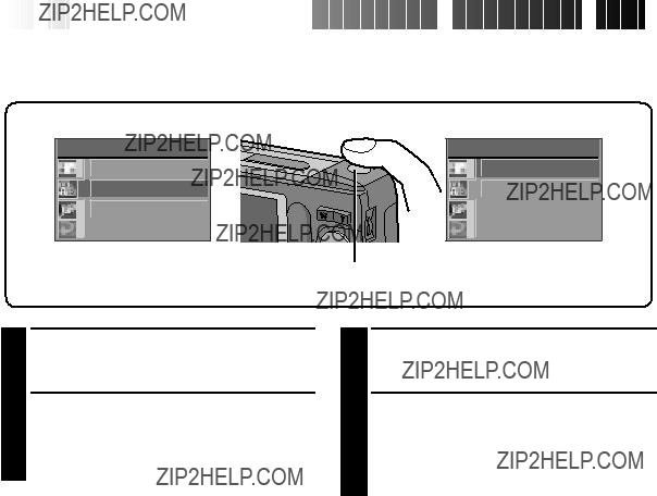


 ADVANCED
 OPERATION


 EN
EN


 ALL
ALL

 EX I T

 EXECUTE


 ADVANCED
 OPERATION


 15
15


 EN
EN


 ADVANCED
 OPERATION


 PLAY MODE
 F I LE
 COMM . MODE
 EX I T

 PC MODE

 EX I T


 EN
EN


 CONTROLS,
 CONNECTORS
 AND
AND
 INDICATORS


 OFF
OFF YA
YA !
!


 CONTROLS,
 CONNECTORS
 AND
AND
 INDICATORS


 1
1
 ???/Cloudy ???
 ???/Halogen???
 ???/ Manual White Balance ???
 : Appears when the Power Dial is set to ???
 ???. When the Shutter Release Button is pressed, this indicator blinks and the
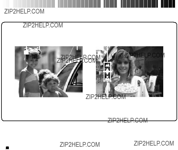


 CONNECTORS
 AND
AND
 INDICATORS


 is displayed.
 is displayed.


 EN
EN


 TROUBLESHOOTING


 EN
EN


 CAUTIONS


 EN
EN


 CAUTIONS


 EN
EN


 MAJOR
MAJOR SPECIFICATIONS


 INDEX
INDEX


 FOR
FOR

 SERVICING

 (Only
(Only

 in
in
 U.S.A.)