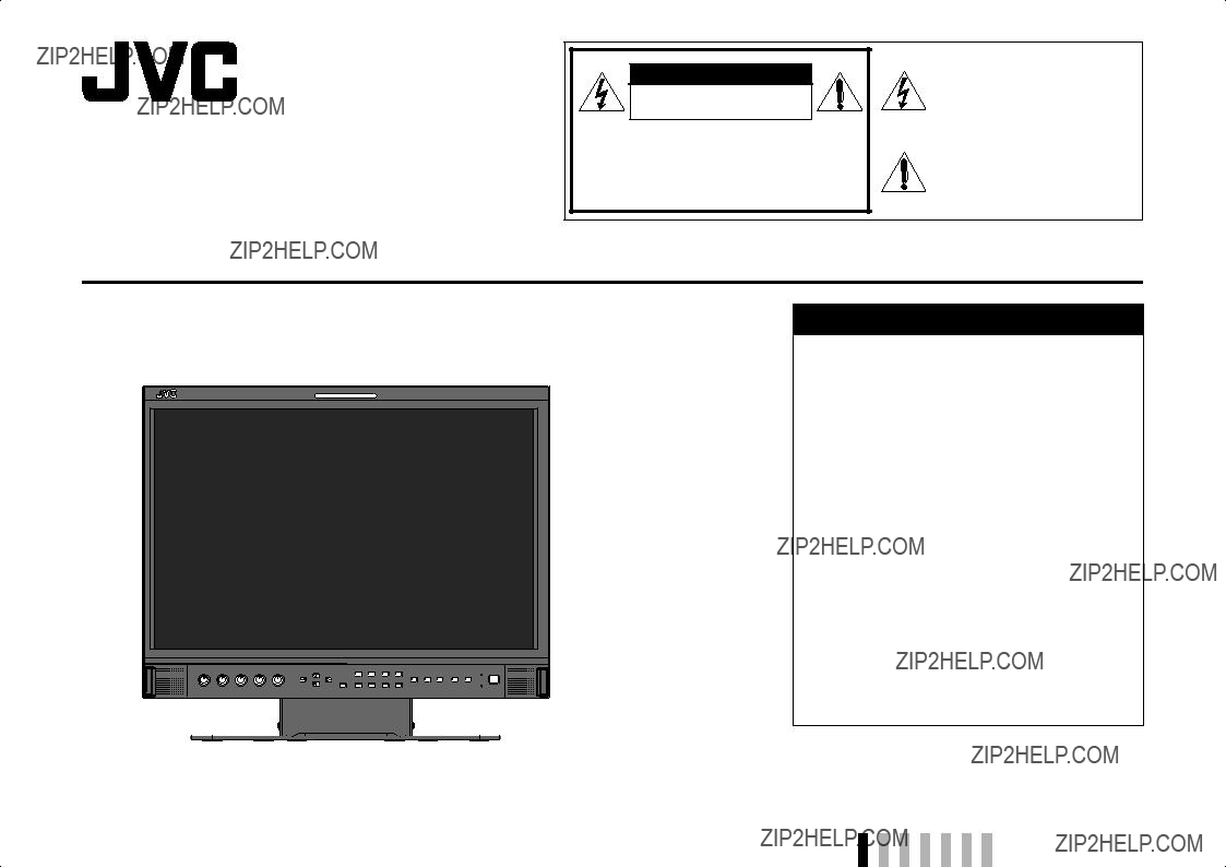
Safety Precautions
WARNING: TO REDUCE RISK OF FIRE OR ELECTRIC SHOCK, DO NOT EXPOSE THIS APPARATUS TO
RAIN OR MOISTURE. NO OBJECTS FILLED WITH LIQUIDS, SUCH AS VASES, SHALL BE
PLACED ON THE APPARATUS.
IMPORTANT SAFEGUARDS
Electrical energy can perform many useful functions. This unit has been engineered and manufactured to assure your personal safety. But IMPROPER USE CAN RESULT IN POTENTIAL ELECTRIC SHOCK OR FIRE. In order not to defeat the safeguards incorporated into this product, observe the following basic rules for its installation, use, and service. Please read these ???IMPORTANT SAFEGUARDS??? carefully before use.
???All the safety and operating instructions should be read before the product is operated.
???The safety and operating instructions should be retained for future reference.
???All warnings on the product and in the operating instructions should be adhered to.
???All operating instructions should be followed.
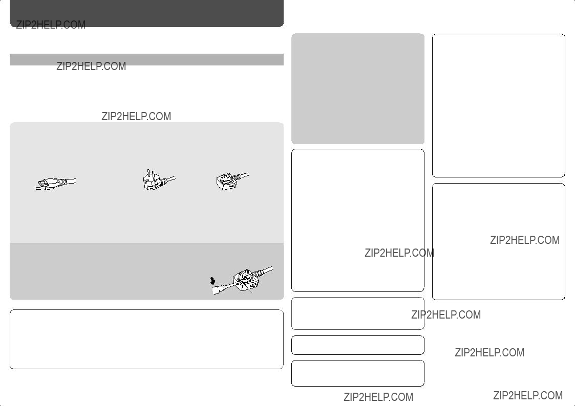
POWER CONNECTION
The power supply voltage rating of this product is AC 120 V (For U.S.A. and Canada) and AC 220 ??? 240 V (For European countries, Asian countries, and United Kingdom).
The power cord attached conforms to the following power supply voltage and countries. Use only the power cord designated to ensure safety and EMC regulations of each country.
This plug will fit only into a grounded power outlet. If you are unable to insert the plug into the outlet, contact your electrician to install the proper outlet. Do not defeat the safety purpose of the grounded plug.
???This product should be operated only with the type of power source indicated on the label. If you are not sure of the type of power supply of your home, consult your product dealer or local electric power company.
Warning:
???Do not use the same power cord for AC 120 V as for AC 220 ??? 240 V. Doing so may cause malfunction, electric shock or fire.
Note for United Kingdom power cord only
The plug of United Kingdom power cord has a built-in fuse. When replacing the fuse, be sure to use only a correctly rated approved type, re-fit the fuse cover. (Consult your dealer or qualified personnel.)
How to replace the fuse
Open the fuse compartment with the blade screwdriver, and replace the fuse.
Fuse
???Before connecting other products such as VCR???s and personal computers, you should turn off the power of this product for protection against electric shock.
???Do not use attachments not recommended by the manufacturer as they may be hazardous.
???When replacement parts are required, be sure the service technician has used replacement parts specified by the manufacturer or equivalents. Unauthorized substitutions may result in fire, electric shock, or other hazards.
???Upon completion of any service or repairs to this product, ask the service technician to perform safety checks to determine that the product is in proper operating condition.
Under the following conditions,
1.Turn off the power.
2.Unplug this product from the wall outlet.
3.Refer service to qualified service personnel. a) When the product emits smoke or unusual
smell.
b) When the product exhibits a distinct change in performance???for example, no picture or no sound.
c) If liquid has been spilled, or objects have fallen on the product.
d) If the product has been exposed to rain or water. e) If the product has been dropped or damaged in
any way.
f) When the power supply cord or plug is damaged.
???Do not install this product in the following places:
???in a damp or dusty room
???where the product is exposed to soot or steam, such as near the cooking counter or a humidifier
???near heat sources
???where condensation easily occurs, such as near the window
???Do not place this product on an unstable cart, stand, or table. The product may fall, causing serious injury to a child or adult, and serious damage to the product.
The product should be mounted according to the manufacturer???s instructions, and should use a mount recommended by the manufacturer.
???Do not use this product near water.
???Be sure to install the product in the place where proper temperature and humidity are kept (??? ???Operating conditions??? on page 17).
This product becomes hot during its use. Take enough care when handling the product.
Do not attempt to service this product yourself, as opening or removing covers may expose you to dangerous voltages and other hazards. Refer all service to qualified service personnel.
Do not use the product for a long time if the sound is distorted.
Use only the power source specified on the unit.
???AC power: 120 V/220 ??? 240 V, 50 Hz/60 Hz
???DC power: 12 ??? 17 V
2
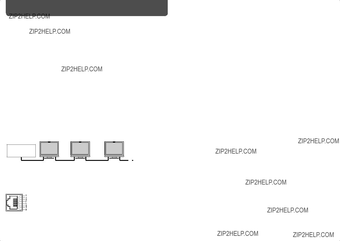
???The AC power supply is controlled by turning on/ off the POWER switch on the rear panel. If the product is installed in a place where you cannot easily turn on/off the POWER switch, control the AC power supply by plugging/unplugging the power cord into/from the AC outlet. In this case, install the product as close to the AC outlet as possible, and leave enough space for plugging/ unplugging the power cord. If the product is installed in a place where you cannot easily plug/unplug the power cord, equip an easily accessible device to the wiring of the building for turning on/off the power.
???When the product is left unattended and unused for a long period of time, unplug it from the wall outlet and disconnect the cable system.
???Do not overload wall outlets, extension cords, or convenience receptacles on other equipment as this can result in a risk of fire or electric shock.
???Use only the accessory cord designed for this product to prevent shock.
???Slots and openings in the cabinet are provided for ventilation. These ensure reliable operation of the product and protect it from overheating.
These openings must not be blocked or covered.
???Never push objects of any kind into this product through openings as they may touch dangerous voltage points or short-circuit the parts, which could result in a fire or electric shock.
???Never spill liquid of any kind on the product.
???Never place anything on the product. (Placing liquids, naked flames, cloths, paper, etc. on the product may cause a fire.)
???Do not apply any strong shock to the LCD panel. (Do not hit any object against it or push it with a sharp-pointed tool.)
???Do not put heavy objects on the product.
???Do not step on or hang on the product.


 Stand body
 (not provided)
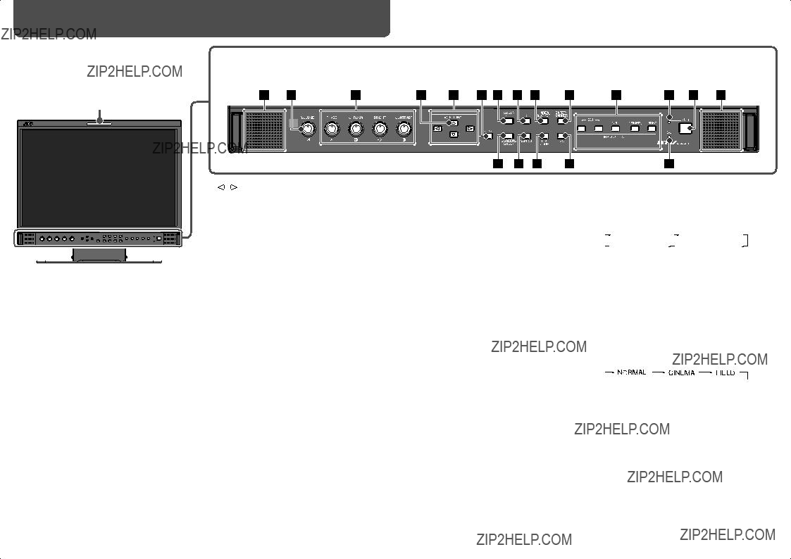
 /
/  buttons
 button while holding
  button displays the
 button
 button while pressing
  button.
 buttons to select an item, then press button.
 buttons to select an item, then press
  buttons to make adjustments.
 buttons to select the left (L ch) or right (R ch).
 buttons to select an audio channel.

 button on the front panel to turn on the monitor after turning on the DC switch.
 button on the front panel to turn on the monitor after turning on the POWER switch.


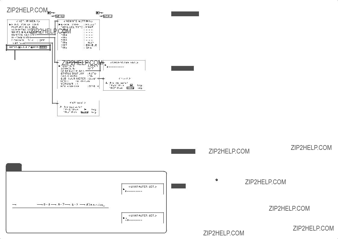

 buttons to select the first character.
 button, the character changes as follows. Press
  button to reverse the order.
 button to move the arrow to the next.
 button while pressing
  button) and turning ???CONTROL LOCK??? to ???OFF???
 Control lock on!??? appears on the screen.