PLASMA DISPLAY MONITOR
PLASMA DISPLAY MONITOR

INSTRUCTIONS
Model
Thank you for purchasing this JVC Monitor.
Before using the monitor, read this manual carefully so that you know how to use the Monitor correctly.
Refer to this manual whenever questions or problems about operation arise. Be sure to read and observe the safety precautions.
Keep this manual where the user can see it easily.
*Installation and removal require special expertise. Consult your product dealer for details.
Contents
1
Safety Precautions
IMPORTANT INFORMATION
WARNING: TO REDUCE THE RISK OF FIRE AND ELECTRIC SHOCK, DO NOT EXPOSE THIS
APPARATUS TO RAIN, MOISTURE, DRIPPING OR SPLASHING AND THAT NO
OBJECTS FILLED WITH LIQUIDS, SUCH AS VASES, SHALL BE PLACED ON THE
APPARATUS.
Warning: This is a class A product. In a domestic environment this product may cause radio interference in which case the user may be required to take adequate measure.
IMPORTANT SAFEGUARDS
Electrical energy can perform many useful functions. This unit has been engineered and manufactured to assure your personal safety. But IMPROPER USE CAN RESULT IN POTENTIAL ELECTRICAL SHOCK OR FIRE HAZARD. In order not to defeat the safeguards incorporated into this product, observe the following basic rules for its installation, use and service. Please read these ???Important Safeguards??? carefully before use.
???All the safety and operating instructions should be read before the product is operated.
???The safety and operating instructions should be retained for future reference.
???All warnings on the product and in the operating instructions should be adhered to.
???All operating instructions should be followed.
???Unplug this product from the wall outlet before cleaning. Do not use liquid cleaners or aerosol cleaners. Use a damp cloth for cleaning.
??? Use a vacuum cleaner to get rid of the dust around the intakes (all the openings) on the rear. If a vacuum is not available, use a cloth and wipe it off. Failure to do so will cause internal heat buildup and, therefore, cause damage to the product.
???Do not use attachments not recommended by the product manufacturer as they may be hazardous.
??? Do not use this product near water. Do not use immediately after moving from a low temperature to high temperature, as this causes condensation, which may result in fire, electric shock, or other hazards.
???Do not place this product on an unstable cart, stand, or table. The product may fall, causing serious injury to a child or adult, and serious damage to the product. The product should be mounted according to the manufacturer???s instructions, and should use a mount recommended by the manufacturer.
???When the product is used on a cart, care should be taken to avoid quick stops, excessive force, and uneven surfaces which may cause the product and cart to overturn, damaging equipment or causing possible injury to the operator.
???Slots and openings in the cabinet are provided for ventilation. These ensure reliable operation of the product and protect it from overheating. These openings must not be blocked or covered. (The openings should never be blocked by placing the product on bed, sofa, rug, or similar surface. It should not be placed in a
For proper ventilation, separate the product from other equipment, which may prevent ventilation and keep distance more than 10 cm.
???This product should be operated only with the type of power source indicated on the label. If you are not sure of the type of power supply to your home, consult your product dealer or local power company.
2
???
???For added protection of this product during a lightning storm, or when it is left unattended and unused for long periods of time, unplug it from the wall outlet and disconnect the cable system. This will prevent damage to the product due to lightning and power line surges.
???Do not overload wall outlets, extension cords, or convenience receptacles on other equipment as this can result in a risk of fire or electric shock.
???Never push objects of any kind into this product through openings as they may touch dangerous voltage points or short out parts that could result in a fire or electric shock. Never spill liquid of any kind on the product.
???Do not attempt to service this product yourself as opening or removing covers may expose you to dangerous voltages and other hazards. Refer all service to qualified service personnel.
???Unplug this product from the wall outlet and refer service to qualified service personnel under the following conditions: a)When the power supply cord or plug is damaged.
b)If liquid has been spilled, or objects have fallen on the product.
c) If the product has been exposed to rain or water.
d)If the product operated normally by following the operating instructions. Adjust only those controls that are covered by the Operation Manual, as an improper adjustment of controls may result in damage and will often require extensive work by a qualified technician to restore the product to normal operation.
e)If the product has been dropped or damaged in any way.
f) When the product exhibits a distinct change in performance ??? this indicates a need for service.
???When replacement parts are required, be sure the service technician has used replacement parts specified by the manufacturer or with same characteristics as the original part. Unauthorized substitutions may result in fire, electric shock, or other hazards.
???Upon completion of any service or repairs to this product, ask the service technician to perform safety checks to determine that the product is in proper operating condition.
???The product should be placed more than 30 cm away from heat sources such as radiators, heat registers, stoves, and other products (including amplifiers) that produce heat.
???When connecting other products such as VCR???s, and personal computers, you should turn off the power of this product for protection against electric shock.
???Do not place combustibles behind the cooling fan. For example, cloth, paper, matches, aerosol cans or gas lighters that present special hazards when over heated.
???Use only the accessory cord designed for this product to prevent shock.
???Do not touch the handles on the rear soon after many hours of continuous use. They are so hot and will cause a burn on the hand. If you need to touch the handles, for example, to move the product, wait until the handles are cooled enough.
??? Option terminal: This terminal is intended exclusively to be used to drive the fan motor.
Do not connect any plugs to the terminal other than JVC???s recommended optional parts.


 Polarity of terminal
POWER CONNECTION
The power supply voltage rating of this product is AC 220 V.
Do not use other power cords than the power cord attached to this unit.
3
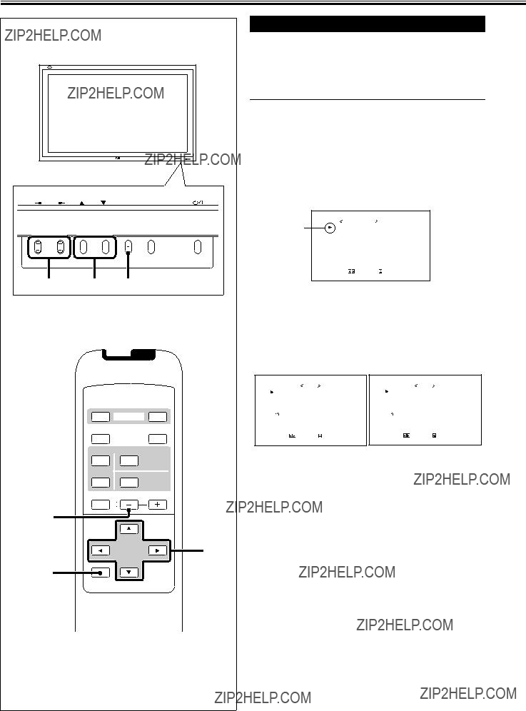
Parts Identification
Remote Control
1 2
2
MENU/EXIT
3OFF POWER ON
DISPLAYASPECT
INPUT SELECT
6


 p
p
7
8
MENU/EXIT
1Remote control cable jack (page 11)
Connect the remote control cable (not supplied) when using this remote control as a wired remote control.
2 Remote signal transmission window
3POWER ON/OFF button (page 14)
Use this button to turn on and off (on standby) the Monitor when the POWER switch on the rear of the Monitor is ???| (on).???
4DISPLAY button (page 14)
Use this button to display the input terminal, color system (for VIDEO A or VIDEO B input), scan system (for COMPONENT input) and horizontal/vertical frequency (for RGB A and RGB B input).
5INPUT SELECT (VIDEO A, VIDEO B, COMPO./(RGB B) and RGB A) buttons
(page 14)
Use these buttons to switch between inputs.
To select the COMPONENT or RGB B input, you have to set ???RGB/COMPO.??? correctly on the menu (see page 22).
6MUTING button (page 14)
Use this button to turn off the volume immediately. Pressing the button again will resume the previous volume level.
72 / 3 / 5 / ??? buttons
Use these buttons to select menu items or make adjustments.
8MENU/EXIT button
Use this button to display or erase menus.
While a
9ASPECT button (page 15)
Use this button to switch between aspect ratios. Each time you press the button, the aspect ratio changes as follows:
 REGULAR
  FULL
FULL
PANORAMIC ZOOM
pVOLUME + / ??? buttons (page 14)
Use these buttons to adjust the volume level.
4

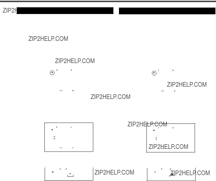
Monitor: Front View
1Remote sensor/power lamp
Point the front end of the wireless remote control toward here.
When the Monitor is turned on, the power lamp glows green. It glows orange in standby mode.
2
These lamps light/flash if something abnormal occurs with the Monitor.
32 / 3 / 5 / ??? buttons
Use these buttons to select menu items and to make adjustments.
???When no menu is displayed, you can use the 2 / 3 buttons to adjust the volume level.
4MENU button
Use this button to display or erase menus.
While a
5INPUT button (page 14)
Use this button to switch between inputs.
To select the COMPONENT or RGB B input, you have to set ???RGB/COMPO.??? correctly on the menu (see page 22).
6 button (page 14)
Use this button to turn on and off (on standby) the Monitor when the POWER switch on the rear of the Monitor is ???| (on).???
5
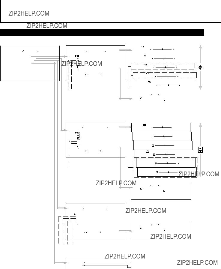
Parts Identification (Continued)
Monitor: Rear Views
1RGB A input terminals (page 11)
Input terminal
Connect to the video output terminal of a personal computer.
Note:
???Use a cord as short as possible when connecting a personal computer to this terminal. (Recommended length is within 3 m.)
AUDIO IN terminal (stereo mini jack)
Connect to the audio output terminal of a personal computer.
2REMOTE terminals (pages 11 and 13)
Connect to the
MAKE terminal (mini DIN, 4pin)
Connect an external control unit. (See page 13.)
WIRED terminal (stereo mini jack)
Connect a wired remote control unit to this terminal.
Note:
???When the above three terminals are used at the same time, transmitted commands through the MAKE terminal have priority over those through the other terminals.
3AUDIO OUT terminals (pin jack) (page 11)
Connect to the audio input terminals of external equipment such as an amplifier.
4AC IN terminal (page 11)
Connect the supplied power cord to this terminal.
5POWER switch (page 14)
When this switch is set to ???| (on),??? you can turn on and off (on standby) the Monitor by using the POWER button on the remote control or the  button on the Monitor.
6OPTION terminal (page 13)
Connect the power cord of the Cooling Fan Unit (not supplied) when installing the Monitor vertically.
7SPEAKER OUT L/R terminals (page 11)
Connect external speakers, such as unique JVC speakers (not supplied), etc.
8INTERNAL/EXTERNAL
6

AUDIO (L/MONO, R) input terminals (pin jack)
Connect these terminals to the audio input terminals of a VCR, etc.
VIDEO IN terminal (BNC)
Connect this terminal to the video output terminal of a VCR, etc.
VIDEO OUT terminal (BNC)
Connect this terminal to the video input terminal of another Monitor, etc.
Note:
???Since the video output terminals on this Monitor are
pVIDEO B terminals (option) (page 12)
AUDIO (L/MONO, R) input terminals (pin jack)
Connect these terminals to the audio output terminals of a VCR, etc.
Y/C (S video) IN terminal (mini DIN 4pin)
Connect this terminal to the
VIDEO IN terminal (pin jack)
Connect this terminal to the video output terminal of a VCR, etc.
Note:
???When both the video and
AUDIO (L/MONO, R) input terminals (pin jack)
Connect these terminals to the audio output terminals of the other equipment.
G, B, R, HD/Cs, VD (VIDEO) input terminals (BNC)
Connect these terminals to the following output terminals of a personal computer or other equipment:
???Analog RGB signal output terminals
???Horizontal sync (HD) signal or composite (Cs) signal output terminal
???Vertical sync (VD) signal output terminal
Notes:
???External sync signals are automatically detected when they come in.
???When both horizontal (HD)/vertical (VD) sync and composite (Cs) sync are connected, HD/VD sync signals will be used.
Y, Pb, Pr (VIDEO) input terminals (BNC)
Connect these terminals to the component signal output terminals of NTSC or
Note:
???When these terminals are used as the component terminals (Y, Pb,
7
Preparations
Checking the Accessories
The following accessories are included with the Monitor. Check for them. If any item is missing, please contact the dealer where you purchased the Monitor.
???Remote control
???Power cord x 1
???Batteries (AA/R6P) x 2
???Ferrite core x 1
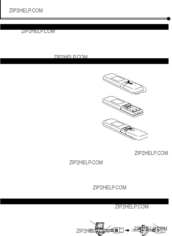
Installing the Batteries
Put the batteries in the remote control as follows. If the remote control has become erratic in operation, change the batteries.
1
2
3
Remove the back cover.
While pushing the release lever on the cover, remove the cover in the direction of the arrow.
Place the batteries.
Put the two supplied batteries (AA/R6P), noting the ?? and ?? markings, as shown.
Replace the back cover as illustrated.
Make sure the release lever on the cover is locked in place correctly.
Precautions for using batteries
If batteries are used improperly, the liquid could leak out, causing a fire, injury, etc. or dirtying the vicinity. Take notice of the following:
???Do not mix old and new batteries.
???Do not mix different types of battery as different types may have different characteristics.
???Place the batteries according to the ?? and ?? markings indicated on the battery compartment.
???When installing the batteries, insert the ?? end first to avoid a short circuit.
???Use only the specified batteries.
???When you are not using the remote control for a long time, remove the batteries.
???When the batteries have reached the end of their life, replace them with new ones immediately. Otherwise, the liquid may leak out, or malfunction may be caused by the leaked liquid. If the leaked liquid contacts your skin, wipe off the liquid with a soft cloth. If the affected skin is left as is, you may get a rough skin.
???Do not throw the batteries into fire or try recharging them.
???The service life of batteries is six months to one year for normal use. The supplied batteries are only for checking the operation and their life may be shorter. When the remote control operation becomes erratic, replace with new batteries.
Attaching the Ferrite Core
Attach the ferrite core to the power cord. Using the power cord without the ferrite core may lead to noise (interference). Open the ferrite core, insert the power cord and close the ferrite core. Attach the ferrite core to the AC IN end of the power cord.
Ferrite core
Power cord
Plug to AC IN
8
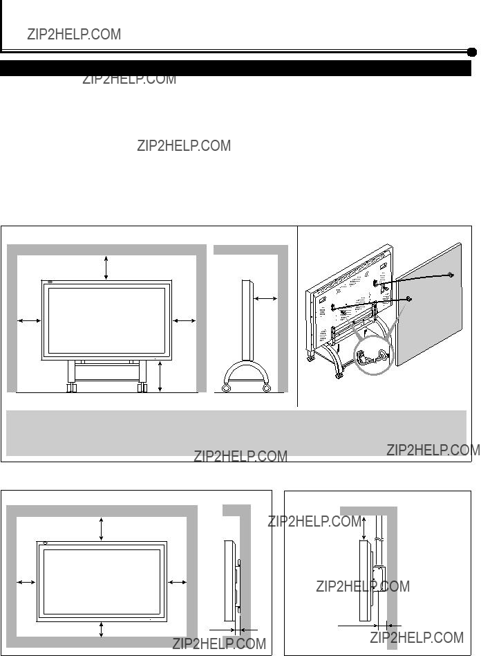
Installation
Precautions
???When mounting the Monitor vertically, consult your dealer. (See also page 13.)
???When installing the Monitor, be sure to use a dedicated Stand Unit, Wall Mounting Unit, or Monitor Hanger Unit, depending on a particular case. Ask your dealer for installation.
???When installing the Monitor, refer also to the user manual for each option to use. Do not tilt the Monitor rightward, leftward, or backward.
???Route the power cord and connection cables along wall or floor corners to avoid walking on them.
???For good heat dissipation, try to leave the following distances of space (minimum) around the Monitor.
???The ambient temperature of the installation place should be within the range of 0??C to 40??C (slightly variable depending on ambient conditions for installation.)
???When installing the Monitor in a place, such as near the ceiling, the remote control may not work correctly because of possible effects from the surroundings. If this happens, use the remote control as a wired remote control or move the Monitor where it is free from these effects.
When installing the Monitor on a stand
Side View
Unit: mm
Take measures against the Monitor from overturning:
To protect against abnormal events such as earthquakes and to prevent unexpected accidents, take appropriate measures for preventing the Monitor from overturning; should it overturn, this could lead to personal injury.
For detailed information, refer to the manual supplied for the stand.
???Do not allow the same image (pattern) to be continuously displayed on the screen for a long time; otherwise, the area on the screen corresponding to the image may vary in brightness, leaving an afterimage on the screen. To reduce the afterimage, you can use the Refresh function (see page 31).
???The Monitor is manufactured using very
???Do not install the Monitor in such a way that the Monitor and other AV equipment affect each other adversely. (For example, if a disturbed image or noise due to electromagnetic interference occurs, or if the infrared remote control malfunctions, change the installation place.)
9
Connections
Precautions
???Before making connections, turn off all the equipment.
???Use a cord whose plugs are correctly matching for the terminals on this Monitor and the equipment.
???Plugs should be firmly inserted; poor connection could cause noise.
???To unplug a cord, be sure to grasp its plug and pull it out.
???Connect the power cord after having finished all other connections.
???Refer also to the user manual of each piece of equipment.
Available Signals
Video signals (option)
The following signals can be input to this Monitor:
???VIDEO A and VIDEO B terminals accept ??? PAL, PAL60, NTSC, NTSC4. 43, and SECAM signals.
???COMPONENT/RGB B terminals accept ??? 480i, 576i, 480p, 576p, 720/60p, 1080/60i (1035/60i), and 1080/50i signals. (You need to set ???RGB/COMPO.??? to ???COMPO.??? on the menu (see page 22).
Computer signals (Preset)
This Monitor has 18 preset video modes for the most popular industrial standard, and the signals of the following image resolutions can be input to the RGB input terminals.
Notes:
???When a signal other than listed above is input, a part of the screen may become void or an unnecessary picture may appear.
???Signals, though they are within the acceptable range of frequencies, may not be displayed normally, depending on the signal type.
???Depending on the connected equipment, the Monitor may not be compatible with composite sync (Cs) or G on sync signals.
???When a preset mode signal is input, the vertical frequency displayed on the screen will have an ???*??? shown at its right top position.
???When the No. 6 signal is input, change the aspect ratio to ???FULL??? with the ASPECT button (page 15) on the remote control or from the ???FUNCTION SELECT??? menu (page 21).
???When No. 8 to No. 16 signals are input, thin lines may become obscure for their signal frequencies are higher than the screen resolution.
10

Connection Diagrams
Typical connections
??? For connection, see page 13.
Amplifier, etc.
Power cord (supplied)
???
To a wall outlet
Ferrite core
??? Make sure to attach the ferrite core to the power cord. See also page 8.
External speaker connection
 ?? ??
?? ??


External speakers
(Ex.


 ?? ??
?? ??
To speaker input terminals
How to connect the cords
To speaker input terminals
When using external speakers, set this to EXTERNAL.
Note:
It is recommended to use the speaker
???Impedance: Between 6 ??? and 8 ???
???Power handling capacity: More than 3 W
Caution:
???Do not
11
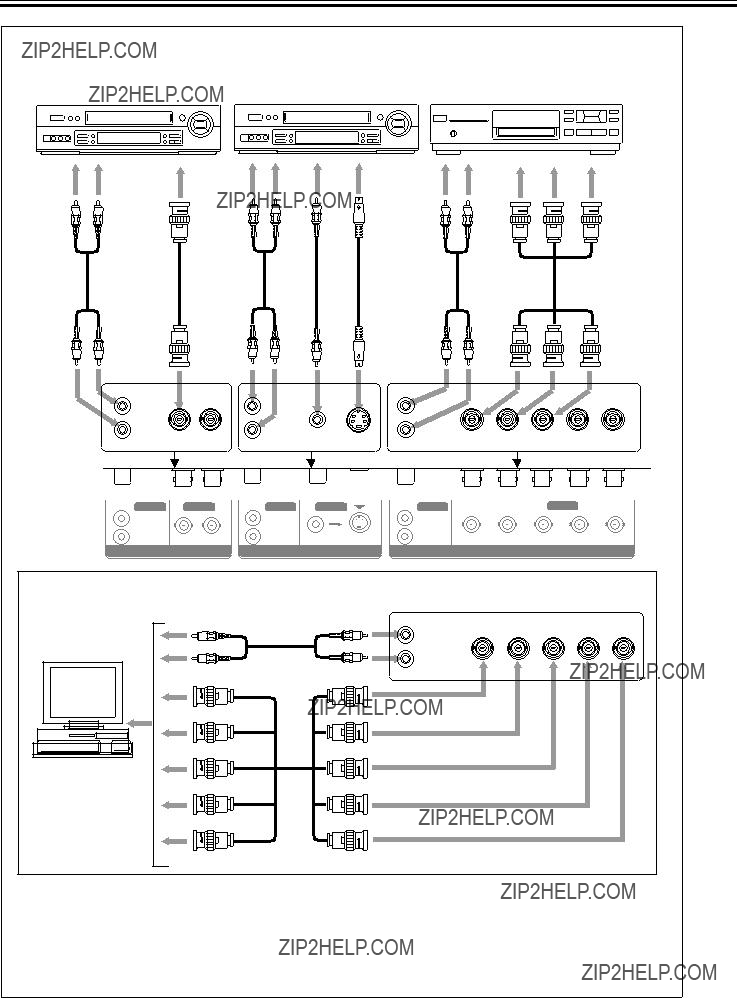
Connections (Continued)
When connecting another PC to the COMPONENT/RGB B terminals, set the ???RGB/COMPO.??? setting to ???RGB??? (see page 22).
Personal computer
(used as the playback
source)
Notes:
???You can connect another VCR or Monitor to the VIDEO A OUT terminal. However, when connecting a VCR to the VIDEO A terminals, do not connect both IN and OUT terminals to the same VCR.
???When connecting a VCR to the VIDEO B terminals, you can use either the video or
12

Connecting an external control unit
When connecting the external control unit to the MAKE terminal, you can operate the following functions through the MAKE terminal;
???Turn on or off the Monitor.
Preparation: The POWER switch on the rear must be set to ???| (on)??? (so that the Monitor is in standby mode).
???Select the input.
Preparation: ???REMOTE SWITCH??? should be set correctly to select your desired input (see page 27).
Notes:
???There is no remote control on/off switch. When a plug is inserted to the MAKE terminal, remote control through the external control unit is automatically activated.
???When the other REMOTE terminals are used at the same time, transmitted commands through the MAKE terminal have priority over those through the other terminals.
??? MAKE terminal
??? External control unit
Signals transmitted
*Input A and Input B will be determined by the ???REMOTE SWITCH??? setting.
IMPORTANT:
External control unit is not commercially available in the market. When you need it, consult your dealer.
Connecting the Cooling Fan Unit (not supplied)
When installing this Monitor vertically, it is required to attach the Cooling Fan Unit.
Note: If you install the Monitor in such a way not instructed in this manual (for example, installing it diagonally), the Cooling Fan Unit may not be able to cool down the internal heat enough to make the Monitor operate; therefore, reinstallation or another method for cooling will be required.
??? For more detailed connection, refer to the manual supplied with the Cooling Fan Unit.
Cooling Fan Unit:
IMPORTANT:
When installing the Monitor vertically, consult your dealer.
13

Basic Operations
Rear View
1
POWER
OFF POWER ON
DISPLAYASPECT
DISPLAY
MUTING
MENU/EXIT
Daily Operations
1 Turn on the main power.
Set POWER on the back of the Monitor to ???| (on)???. The POWER lamp on the upper left of the front panel lights orange.
???If you have turned off the Monitor not by using POWER ON on the remote control (or  on the front panel), but by using the POWER switch, setting the power switch to ???| (on)??? lights the power lamp green and turns the Monitor on.
2 Turn on the power.
Press POWER ON on the remote control to turn the power on.
The POWER lamp lights green.
???You can also use the  on the front panel (lower right) to turn on the Monitor.
3 Select an input.
Select the desired input by pressing INPUT SELECT (VIDEO A, VIDEO B, COMPO./(RGB B) and RGB A).
???You can also select the input by pressing INPUT on the Monitor. Each time you press the button, the input mode changes in sequence.
Ex. When selecting ???VIDEO A??? input
V I D E O A
N T S C
Input selected
Input video signal
2 Note:
???To select ???COMPONENT??? or ???RGB B,??? you need to set the ???RGB/COMPO.??? setting correctly.
4 Adjust the volume.
4 Note:
???While no menu is displayed, you can adjust the volume by pressing 2 / 3 on the Monitor.
To turn off the volume immediately
Press MUTING.
???MUTING ON??? is displayed, and the sound goes out. Pressing the button again resumes the previous volume level.
To make the screen indication appear
Press DISPLAY.
The types of input and signal are indicated on the screen for about 3 seconds.
You can also make the screen indication appear using menus (page 24).
14
Changing the Aspect Ratio
With this Monitor, you can select among three types of wide screens (FULL, ZOOM, and PANORAMIC) in addition to the REGULAR screen of conventional 4:3 aspect ratio.
MENU/EXIT
ZOOM:REGULAR size display is enlarged vertically and horizontally at the same ratio.
Precautions for using the screen mode switching function
???This Monitor features a screen mode switching (aspect ratio change) function. If you select a mode different in aspect ratio from software such as TV programs, the picture may look different from original picture. Be aware of this point when you are selecting a screen mode.
???If you select a wide screen mode while viewing conventional video programs of the aspect ratio 4:3, some portions (edges) of the original picture will be cut off, or deformed. To enjoy the original picture as it is, select ???REGULAR??? while viewing such programs.
???If you place the Monitor in a tea room, hotel, etc. for business purposes or public viewing and modify the picture by using the screen mode switching (aspect ratio change) function, this could violate the copyright protected by the copyright law, which requires your special attention.
???If you make the screen very bright and watch programs selecting ???REGULAR,??? for a long period of time, the Monitor screen may happen to be burned in. If this occurs, watching programs using a wide screen mode for a while will reduce the
PANORAMIC: REGULAR size display is enlarged horizontally to the extent that the picture does not look abnormally.
Notes:
???When one of the following signals is being input, you cannot select the aspect ratio you want.
???720/60p, 1080/60i (1035/60i), or 1080/50i signal through the COMPONENT/RGB B input terminals
You can only select FULL.
???When any signal other than
You can select only REGULAR and FULL.
???The aspect ratio can also be changed on the Function Selection Menu (page 21).
15

To make an adjustment while viewing the adjustment bar
After step 3 on page 16, proceed as follows:
1Press 5/??? to move the cursor (3) to ???sub menu.???
2Press 3 to display the Sub Menu.
The Sub Menu for CONTRAST appears on the screen.
3 Press 3 to display the Size/Position
Adjustment Menu.
3Press 5/??? to select the Sub Menu you want to adjust.
Each time you press the button, the Sub Menu changes as follows:
CONTRAST BRIGHT CHROMA
SHARPNESSPHASE
4Press 2/3 to adjust the selected item.
5Repeat steps 3 and 4 to adjust the other items.
6Press MENU/EXIT (or MENU on the Monitor) three times to exit from the menu operations.
To reset the adjustments
After step 3 on page 16, proceed as follows:
1Press 5/??? to move the cursor (3) to ???reset.???
2Press 3.
The confirmation screen appears.
" N O " t h e n M E N U k e y .
3Press 3 again to reset the adjustments.
To cancel the reset, press MENU/EXIT (or MENU on the Monitor).
Adjusting the Screen Size and Position
The screen size and position can be adjusted.
Adjusted settings can be stored for each signal type; therefore, when the same signal comes in, the stored settings are recalled.
???When adjusting the size, the size cannot be adjusted proportionally, but can be enlarged rightward (or downward) only and reduced leftward (or upward) only. Therefore, it is necessary to adjust both the size and position alternately to adjust to the appropriate size.
1 Press MENU/EXIT (or MENU on the Monitor) to display the Main Menu.
2 Press 5/??? to move the cursor (3) to ???SIZE/POSITION ADJ.???
*Appearing and being adjustable only when you use RGB A or RGB B input.
4 Press 5/??? to move the cursor (3) to the item you want to adjust.
*1 Size and position adjustments are so related that if one is adjusted much, the other???s adjustable range will be reduced.
*2 DOT CLOCK is the function to adjust the pixel sampling number of the A/D converter to the resolution (the vertical pixel number) of the input signal.
CLOCK PHASE is the function to adjust the sampling timing (phase) to the phase of the input signal.
You can use the two functions to reduce flickering and blurring on the screen when using the RGB A or RGB B input.
5 Press 2/3 to adjust the selected item.
Note:
???During size and position adjustments, the Monitor screen may be distorted. This is normal, but not a malfunction of the Monitor.
6 Press MENU/EXIT (or MENU on the Monitor) twice to exit from the menu operations.
(To be continued on the next page)
17

Adjusting the Color Temperature
The adjusted setting applies to all inputs.
1 Press MENU/EXIT (or MENU on the Monitor) to display the Main Menu.
2 Press 5/??? to move the cursor (3) to
???FUNCTION SELECT.???
3 Press 3 to display the Function
Selection Menu.
4 Press 5/??? to move the cursor (3) to ???COLOR TEMP.???
5 Press 2/3 to make an adjustment.
Each time you press the button, the color temperature alternates between ???HIGH??? and ???LOW.???
HIGH: To make the screen become bluish.
LOW: To make the screen become reddish.
Adjusting the White Balance
G GAIN, B GAIN and R GAIN can be finely adjusted separately for ???HIGH??? and ???LOW??? settings of the color temperature.
1 On the remote control:
Press MENU/EXIT while holding VOLUME ??? to display the Setup Menu.
On the Monitor:
Press MENU while holding 2 to display the Setup Menu.
2 Press 5/??? to move the cursor (3) to ???WHITE BALANCE.???
???The Setup Menu consists of two pages. If you keep pressing 5/???, you can move to the other page from the current page.
3 Press 3 to display the White Balance
Adjustment Menu.
W H I T E B A L A N C E : H I G H
s u b m e n u  r e s e t
A D J U S T :
 S E L E C T :
 E X I T : M E N U
6 Press MENU/EXIT (or MENU on the Monitor) twice to exit from the menu operations.
Note:
???To make a fine adjustment, adjust ???WHITE BALANCE??? (see the right column).
4 Press 5/??? to move the cursor (3) to the item you want to adjust.
5
6 Repeat steps 4 and 5 to adjust the other items.
7 Press MENU/EXIT (or MENU on the Monitor) twice to exit from the menu operations.
Notes:
???Adjustable range will vary among the Monitors.
??????MAX??? may appear soon after you begin adjustment. This is normal but not a malfunction.
19
Video Adjustments (Continued)
MENU INPUT
OFF POWER ON
DISPLAYASPECT
2 / 3
5 / 5
MENU/EXIT
MENU/EXIT
*1 ???ASPECT??? does not appear when 720/60p, 1080/60i (1035/60i), or 1080/50i signal is being input through the COMPONENT/RGB B input terminals.
*2 ???SIGNAL MODE??? appears only when VIDEO A, VIDEO B, or COMPONENT input is selected.
*3 ???RGB/COMPO.??? appears only when the RGB B or COMPONENT input is selected.
*4 ???SYNC TERM.??? appears only when the RGB B input is selected.
To make an adjustment while viewing the adjustment bars
After step 3 on page 19, proceed as follows:
1Press 5/??? to move the cursor (3) to ???sub menu.???
2Press 3 to display the Sub Menu.
The Sub Menu for R GAIN appears on the screen.
3Press 5/??? to select the Sub Menu you want to adjust.
Each time you press the button, the Sub Menu changes as follows:
 R GAIN
  G GAIN
B GAIN
4Press 2/3 to adjust the selected item.
5Repeat steps 3 and 4 to adjust the other items.
6Press MENU/EXIT (or MENU on the Monitor) three times to exit from the menu operations.
To reset the adjustments
After step 3 on page 19, proceed as follows:
1Press 5/??? to move the cursor (3) to ???reset.???
2Press 3.
The confirmation screen appears.
" N O " t h e n M E N U k e y .
3Press 3 again to reset the adjustments.
To cancel the reset, press MENU/EXIT (or MENU on the Monitor).
20

The setting adjusted applies to all inputs.
???You can change the aspect ratio by pressing ASPECT. (See page 15.)
1 Press MENU/EXIT (or MENU on the Monitor) to display the Main Menu.
2 Press 5/??? to move the cursor (3) to
???FUNCTION SELECT.???
3 Press 3 to display the Function
Selection Menu.
F U N C T I O N S E L E C T
*1 *2 *3 *4
4
5 Press 2/3 to select an aspect ratio you want.
Each time you press the button, the aspect ratio changes as follows:
 REGULAR
  FULL
FULL
PANORAMIC ZOOM
ZOOM 
*For detailed information on these aspect ratios, see page 15.
6 Press MENU/EXIT (or MENU on the Monitor) twice to exit from the menu operations.
Note:
???When one of the following signals is being input, you cannot select the aspect ratio you want.
???720/60p, 1080/60i (1035/60i), or 1080/50i signal through the COMPONENT/RGB B input terminals
Aspect ratio is fixed to FULL (???ASPECT??? does not appear on the display).
???When any signal other than
You can select only REGULAR and FULL.
You can set the receivable signal types. Normally, select ???AUTO.???
A common setting will apply to both the VIDEO A input and the VIDEO B input, and a different setting will apply to the COMPONENT input.
1 Press MENU/EXIT (or MENU on the Monitor) to display the Main Menu.
2 Press 5/??? to move the cursor (3) to
???FUNCTION SELECT.???
3 Press 3 to display the Function
Selection Menu.
F U N C T I O N S E L E C T
*1 *2 *3 *4
4 Press 5/??? to move the cursor (3) to ???SIGNAL MODE.???
5 Press 2/3 to select the receivable video signal type.
Each time you press the button, the receivable video signal type changes as follows:
??? When VIDEO A or VIDEO B input is selected:
 AUTO
AUTO
 NTSC
NTSC 
 PAL
PAL 
 PAL60
PAL60 
 N4.43
N4.43 
 SECAM
SECAM 
(NTSC4.43)
??? When COMPONENT input is selected:
 AUTO
AUTO
 480i
480i 
 576i
576i
 480p
480p
 1080/50i
 1080/60i
 720p
720p
 576p
576p (1035i)*
*Changes according to the ???HD SIGNAL MODE??? setting (see page 27).
6 Press MENU/EXIT (or MENU on the Monitor) twice to exit the menu operations.
21
Video Adjustments (Continued)
MENU INPUT
OFF POWER ON
DISPLAYASPECT
2 / 3
5 / 5
MENU/EXIT
MENU/EXIT
*1 ???ASPECT??? does not appear when 720/60p, 1080/60i (1035/60i), or 1080/50i signal is being input through the COMPONENT/RGB B input terminals.
*2 ???SIGNAL MODE??? appears only when VIDEO A, VIDEO B, or COMPONENT input is selected.
*3 ???RGB/COMPO.??? appears only when the RGB B or COMPONENT input is selected.
*4 ???SYNC TERM.??? appears only when the RGB B input is selected.
Setting the COMPONENT/RGB B Input
After connecting the playback device such as a PC or a DVD player to the COMPONENT/RGB B terminals, you have to specify which type of signal comes into this
???Without setting ???RGB/COMPO.??? correctly, you cannot show any picture though you select the COMPONENT or RGB B input.
1 Press MENU/EXIT (or MENU on the Monitor) to display the Main Menu.
2 Press 5/??? to move the cursor (3) to
???FUNCTION SELECT.???
3 Press 3 to display the Function
Selection Menu.
F U N C T I O N S E L E C T
*1 *2 *3 *4
4 Press 5/??? to move the cursor (3) to ???RGB/COMPO.???
5 Press 2/3 to select the type of signal.
COMPO.: When connecting the playback device such as a DVD player, which can emit the component signals.
RGB: When connecting the playback device such as a PC, which can emit the RGB signals.
The setting changes and the ???FUNCTION SELECT??? Menu disappears.
22
Changing the Resistance of the RGB B
Input Terminals
You can set the resistance of the two of the RGB B input terminals to either HIGH (1 k???) or LOW (75 ???):
???HD/Cs (Horizontal sync/Composite) terminal
???VD (Vertical sync) terminal.
HIGH is the normal setting. Change the setting to LOW when you use a long connecting cord and the picture flickers and blurs on the screen.
1 Press MENU/EXIT (or MENU on the Monitor) to display the Main Menu.
2 Press 5/??? to move the cursor (3) to
???FUNCTION SELECT.???
3 Press 3 to display the Function
Selection Menu.
F U N C T I O N S E L E C T
*1 *2 *3 *4
4 Press 5/??? to move the cursor (3) to ???SYNC TERM.???
5 Press 2/3 to select the terminal resistance.
Each time you press the button, the resistance alternates between ???HIGH??? and ???LOW.???
HIGH: Initial setting. Normally select this.
LOW: When using a long connecting cord and the picture flickering and blurring on the screen.
6 Press MENU/EXIT (or MENU on the Monitor) twice to exit the menu operations.
Resetting the Function Selection Menu Settings
You can reset all the Function Selection Menu settings at a time.
1 Press MENU/EXIT (or MENU on the Monitor) to display the Main Menu.
2 Press 5/??? to move the cursor (3) to
???FUNCTION SELECT.???
3 Press 3 to display the Function
Selection Menu.
F U N C T I O N S E L E C T
*1 *2 *3 *4
4 Press 5/??? to move the cursor (3) to ???reset.???
5 Press 3.
The confirmation screen appears.
" N O " t h e n M E N U k e y .
6 Press 3 again to reset the adjustments.
To cancel the reset, press MENU/EXIT (or MENU on the Monitor).
7 Press MENU/EXIT (or MENU on the Monitor) twice to exit the menu operations.
23
Confirming the Use Time and Model Name
You can confirm the hours of use and the model name on the Setup Menu.
This may be necessary when you ask for any service.
1 On the remote control:
Press MENU/EXIT while holding VOLUME ??? to display the Setup Menu.
On the Monitor:
Press MENU while holding 2 to display the Setup Menu.
W H I T E B A L A N C E
T I M E R
A D J U S T :
 S E L E C T :
 E X I T : M E N U
2 Keep pressing 5/??? until the second page of the Setup Menu appears.
???The Setup Menu consists of two pages. If you keep pressing 5/???, you can move to the other page from the current page.
3 Confirm the hour of use and model name.
???The displayed value for the hours of use is divided by 100. To calculate the actual hours of use, multiply the displayed value by 100.
4 Press MENU/EXIT (or MENU on the Monitor) once to exit from the menu operations.
Notes:
???The value for the hours of use is added by one hour unit. If you use the Monitor within one hour, it will not be added to the hours of use.
???The period when the Monitor is on standby (the power lamp glows orange) will not be added to the hours of use.
Showing the
the Input Mode
With this function, you can see the selected input mode and signal type when changing the input mode.
1 On the remote control:
Press MENU/EXIT while holding VOLUME ??? to display the Setup Menu.
On the Monitor:
Press MENU while holding 2 to display the Setup Menu.
2 Press 5/??? to move the cursor (3) to
???STATUS DISPLAY.???
???The Setup Menu consists of two pages. If you keep pressing 5/???, you can move to the other page from the current page.
3 Press 2/3 to select the desired setting.
Each time you press the button, the Status Display function alternates between ???ON??? and ???OFF.???
To cancel the Status Display function, select ???OFF.???
4 Press MENU/EXIT (or MENU on the Monitor) once to exit from the menu operations.
25
Setting the
When connecting the external control unit to the REMOTE MAKE terminal, you need to set the desired input to use, which you can select from the connected external control unit.
1 On the remote control:
Press MENU/EXIT while holding VOLUME ??? to display the Setup Menu.
On the Monitor:
Press MENU while holding 2 to display the Setup Menu.
2 Press 5/??? to move the cursor (3) to ???REMOTE SWITCH.???
???The Setup Menu consists of two pages. If you keep pressing 5/???, you can move to the other page from the current page.
3 Press 2/3 to select the desired setting.
Each time you press the button, the Remote Switch Mode changes as follows:
MODE1: Input alternates between ???VIDEO A??? and  ???VIDEO B??? when controlled from the external control unit.
MODE2: Input alternates between ???VIDEO A??? and ???COMPONENT/RGB B??? when controlled from the external control unit.
MODE3: Input alternates between ???VIDEO A??? and ???RGB A??? when controlled from the external control unit.
MODE4: Input alternates between ???VIDEO B??? and ???COMPONENT/RGB B??? when controlled from the external control unit.
MODE5: Input alternates between ???VIDEO B??? and ???RGB A??? when controlled from the external control unit.
MODE6: Input alternates between ???COMPONENT/ RGB B??? and ???RGB A??? when controlled from the external control unit.
4 Press MENU/EXIT (or MENU on the Monitor) once to exit from the menu operations.
Setting the
You can select one of the
???Without setting ???RGB/COMPO.??? correctly, you cannot show any picture though you select the COMPONENT input (see page 22).
1 On the remote control:
Press MENU/EXIT while holding VOLUME ??? to display the Setup Menu.
On the Monitor:
Press MENU while holding 2 to display the Setup Menu.
2 Press 5/??? to move the cursor (3) to ???HD SIGNAL MODE.???
???The Setup Menu consists of two pages. If you keep pressing 5/???, you can move to the other page from the current page.
3 Press 2/3 to select the desired setting.
Each time you press the button, the HD signal type alternates between ???1080i??? and ???1035i.???
???You can select either ???1080i??? and ???1035i??? according to the HD signal you input ??? whichever gives you proportionally shaped pictures.
4 Press MENU/EXIT (or MENU on the Monitor) once to exit from the menu operations.
27

??? Using the Power On/Off Timer
Select the item you want to set in step 3 in ???Setting the Clock??? (page 28) and follow the instructions below.
You can activate/deactivate the
Press 2/3 to select ???ON??? or ???OFF.???
ON: The Monitor automatically turns on at the time set in
OFF: The
You can adjust the time to turn on the Monitor.
Set the hour and minute following steps 4 to 6 in ???Setting the Clock??? (page 28).
You can activate/deactivate the
Press 2/3 to select ???ON??? or ???OFF.???
ON: The Monitor automatically turns off at the time set in
OFF: The
You can adjust the time to turn off the Monitor.
Set the hour and minute following steps 4 to 6 in ???Setting the Clock??? (page 28).
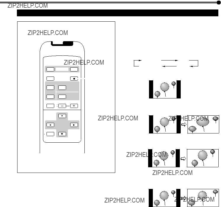
Using the Pixel Shift Function
This function periodically shift the position (pixels) of the displayed picture on the screen so that you can avoid the screen from being burned in.
1 On the remote control:
Press MENU/EXIT while holding VOLUME ??? to display the Setup Menu.
On the Monitor:
Press MENU while holding 2 to display the Setup Menu.
2 Press 5/??? to move the cursor (3) to ???PIXEL SHIFT??? (on the second page).
???The Setup Menu consists of two pages. If you keep pressing 5/???, you can move to the other page from the current page.
 a l l r e s e t
H O U R M E T E R x 1 0 0 h : 1 2 3
3 Press 2/3 to select the desired setting.
Each time you press the button, the Pixel Shift function alternates between ???ON??? and ???OFF.???
To cancel the Pixel Shift function, select ???OFF.???
4 Press MENU/EXIT (or MENU on the Monitor) once to exit from the menu operations.
Using the Power Save Function
You can use this function to reduce the electrical consumption and to extend the lifetime of the Monitor???s screen.
??? The brightness of the screen will be reduced.
1 On the remote control:
Press MENU/EXIT while holding VOLUME ??? to display the Setup Menu.
On the Monitor:
Press MENU while holding 2 to display the Setup Menu.
2 Press 5/??? to move the cursor (3) to ???POWER SAVE??? (on the second page).
???The Setup Menu consists of two pages. If you keep pressing 5/???, you can move to the other page from the current page.
3 Press 2/3 to select the desired setting.
SAVE1: The screen gets dim.
SAVE2: The screen gets dimmer.
OFF: The Power Save function is deactivate.
To cancel the Power Save function, select ???OFF.???
4 Press MENU/EXIT (or MENU on the Monitor) once to exit from the menu operations.
29

START TIME
You can adjust the time to activate the function.
???Set the hour and minute following steps 4 to 6 in ???Setting the Clock??? (page 28).
END SET
You can activate/deactivate the
???Press 2/3 to select ???ON??? or ???OFF.???
ON: The function is automatically deactivated at the time set in ???END TIME.???
OFF: The
END TIME
You can adjust the time to deactivate the function.
???Set the hour and minute following steps 4 to 6 in ???Setting the Clock??? (page 28).
4 Press MENU/EXIT (or MENU on the Monitor) repeatedly to exit from the menu operations.
Note:
???The
3 Press 5/??? to select the item you want to set and set the item as follows.
REFRESH
You can activate/deactivate the function manually.
???Press 2/3 to select the desired setting.
ON: The function is activated immediately after exiting the menu operations.
OFF: The function is deactivated.
TIMER: Select this when you use the Refresh On/Off
Timer.
Note:
???Set the clock (see page 28) and select ???TIMER,??? before using the Refresh On/Off Timer.
START SET
You can activate/deactivate the Refresh On Timer.
???Press 2/3 to select ???ON??? or ???OFF.???
ON: The function is automatically activated at the time set in ???START TIME.???
OFF: The Refresh On Timer is deactivated.
START TIME
You can adjust the time to activate the function.
???Set the hour and minute following steps 4 to 6 in ???Setting the Clock??? (page 28).
Refreshing the Screen
After the power is turned off, a whitish image may be left on the screen. In that case, leave the monitor in a white back state for a while, and the image will disappear.
You can activate/deactivate the function with the Refresh On/Off Timer.
1 On the remote control:
Press MENU/EXIT while holding VOLUME ??? to display the Setup Menu.
On the Monitor:
Press MENU while holding 2 to display the Setup Menu.
2 Press 5/??? to move the cursor (3) to ???REFRESH??? (on the second page) then press 3.
???The Setup Menu consists of two pages. If you keep pressing 5/???, you can move to the other page from the current page.
END SET
You can activate/deactivate the Refresh Off Timer.
???Press 2/3 to select ???ON??? or ???OFF.???
ON: The function is automatically deactivated at the time set in ???END TIME.???
OFF: The Refresh Off Timer is deactivated.
END TIME
You can adjust the time to deactivate the function.
???Set the hour and minute following steps 4 to 6 on ???Setting the Clock??? (page 28).
4 Press MENU/EXIT (or MENU on the Monitor) repeatedly to exit from the menu operations.
Note:
???The Refresh function requires considerable time to reduce the afterimage. Deactivate the function temporarily at intervals of 30
31

Resetting All the Setup Menu Settings
You can reset all the following Setup Menu settings at a time, except the use time (HOUR METER).
1 On the remote control:
Press MENU/EXIT while holding VOLUME ??? to display the Setup Menu.
On the Monitor:
Press MENU while holding 2 to display the Setup Menu.
2 Press 5/??? to move the cursor (3) to ???reset??? (on the second page).
???The Setup Menu consists of two pages. If you keep pressing 5/???, you can move to the other page from the current page.
3 Press 3.
The confirmation screen appears.
" N O " t h e n M E N U k e y .
Resetting All the Menu Settings
You can reset all the Menu settings and adjustments at a time, except the use time (HOUR METER).
1 On the remote control:
Press MENU/EXIT while holding VOLUME ??? to display the Setup Menu.
On the Monitor:
Press MENU while holding 2 to display the Setup Menu.
2 Press 5/??? to move the cursor (3) to ???all reset??? (on the second page).
???The Setup Menu consists of two pages. If you keep pressing 5/???, you can move to the other page from the current page.
3 Press 3.
The confirmation screen appears.
" N O " t h e n M E N U k e y .
4
5
To cancel the reset, press MENU/EXIT (or MENU on the Monitor).
Press 3 again to reset all the Setup
Menu settings.
Press MENU/EXIT (or MENU on the Monitor) once to exit from the menu operations.
To cancel the reset, press MENU/EXIT (or MENU on the Monitor).
4 Press 3 again to reset all the Menu settings and adjustments.
The power is turned off, then turned on again automatically.
33
Menu Classifications
Main Menu
Main Menu
M A I N M E N U
 P I C T U R E A D J .
S I Z E / P O S I T I O N A D J .
F U N C T I O N S E L E C T
S T A T U S D I S P L A Y
E N T E R :  S E L E C T :
  E X I T : M E N U
Picture Adjustment Menu
Size/Position Adjustment Menu
 H S I Z E
++ 
 H P O S I T I O N
++ 
 V S I Z E
++++
:+ 0 1
 ++
++
:+ 0 1
 ++
++
:+ 0 1
 ++ ++
++ ++
:+ 0 1
 ++
++
:+ 0 1
+
: + 0 1
+
Function Selection Menu
F U N C T I O N S E L E C T
*4 *5 *6 *7
Status Display
V I D E O A
N T S C
Ex. When ???VIDEO A??? input is selected.
k e y . k e y .
k e y . k e y .
34

PICTURE ADJ. (Picture adjustment): See page 16.
SIZE/POSITION ADJ. : See page 17.
FUNCTION SELECT: See pages 19 to 23.
STATUS DISPLAY: See page 24.
Shows the input mode and signal type on the screen.
*1 Adjustable when viewing the NTSC, PAL or SECAM signal, or component signal. *2 Adjustable when viewing the NTSC signal or component signal.
*3 Adjustable when RGB A or RGB B input is selected.
*4 Not adjustable when viewing the following component
*5 Adjustable when VIDEO A, VIDEO B, or COMPONENT input is selected. *6 Adjustable when RGB B or COMPONENT input is selected.
*7 Adjustable when RGB B input is selected.
35

Menu Classifications (Continued)
Setup Menu
 To ???Reset Confirmation Screen???

STATUS DISPLAY: See page 25.
Sets if you want the input terminal and the type of signal to be indicated on the screen just after inputs are switched.
CONTROL LOCK: See page 26.
Sets the Monitor so that it cannot be operated with the buttons on itself.
REMOTE SWITCH: See page 27.
Set the selectable input terminals when controlling the Monitor with the external control unit.
HD SIGNAL MODE: See page 27.
Select the
WHITE BALANCE: See page 19.
Adjusts R GAIN, G GAIN and B GAIN finely each for ???HIGH??? and ???LOW??? settings of the color temperature.
TIMER: See page 28.
Sets the clock and the Power On/Off Timer.
PIXEL SHIFT: See page 29.
Sets a screen saver.
POWER SAVE: See page 29.
Sets the power save function.
Use to reduce the afterimage on the screen of the still picture by reversing the color.
REFRESH: See page 31.
Use to reduce the whitish image remaining on the screen after turning off the power.
reset: See page 33.
Resets the Setup Menu settings to defaults.
all reset: See page 33.
Resets the all menu settings and adjustments to defaults.
HOUR METER x 100h: See page 25.
Use to confirm the hours of use.
MODEL NAME: See page 25.
Use to confirm your model name.
37

Troubleshooting
Solutions to common problems related to the Monitor are described here. If none of the solutions presented here solves the problem, unplug the Monitor and consult an authorized dealer or service center.
38

When something abnormal occurs with the Monitor, this function informs you of the condition of the Monitor with
Remote sensor
1
2
3
Power lamp
???If the screen monitor turns off and
If the
???If
This may be caused by the dusty intakes on the rear. If this happens, switch off the main power by POWER switch (set to ?????? (off)???), unplug the AC power cord, then clean the intakes by referring to the instruction on page 2.
???After cleaning, switch on the Monitor???s main power again. If
???If the screen monitor dims a little and ???TEMP. OVER??? lights (or flashes)
If ???TEMP. OVER??? lights or flashes at the right bottom of the screen, check the following before consulting the dealer where you purchased the Monitor.
???TEMP. OVER??? appears to warn you of the internal heat buildup, which is usually caused by accumulated dust around the intakes or by improper installation. If the cause of the internal heat buildup is eliminated, this indication disappears and the screen recovers the brightness.
???If ???TEMP. OVER??? flashes in yellow
This may be caused by the dusty intakes on the rear. If this happens, switch off the main power by POWER switch (set to ?????? (off)???), unplug the AC power cord, then clean the intakes by referring to the instruction on page 2.
???After cleaning, switch on the Monitor???s main power again. If ???TEMP. OVER??? still flashes, this trouble may be caused by improper installation or improper location of the Monitor. In this case, consult your dealer immediately to solve this improper installation and to improve the circumstances around the Monitor.
???If ???TEMP. OVER??? lights in red
???TEMP. OVER??? will be shown for abut two minutes, the Monitor will shut off automatically, then the Self- diagonal lamps light in red. If this happens, switch off the main power by POWER switch (set to ?????? (off)???), unplug the AC power cord, then consult your dealer immediately.
If the trouble still persists, follow the procedure below:
1 Check which lamps are lighting or flashing.
On the
???Only one lamp may light or flash, or all three lamps may do so.
2 Switch off the POWER switch on the back of the Monitor.
3
4 Call your dealer and tell which lamps are lighting or flashing. (Copy and fax the
Note:
If you switch on the main power immediately after switching it off (or after recovering from a brief power interruption), the
Store name where you purchased the Monitor
To
Model Name:
Plasma Display Monitor
The
Your Name:
Telephone No.:
Address:
39
Specifications
General
Input/output terminals
*To use the COMPONENT/RGB B terminals either as the COMPONENT input terminal or as the RGB B input terminal, you need to set ???RGB/COMPO.??? correctly (see page 22).
???For easy understanding, pictures and illustrations are shown by being emphasized, omitted or composed, and may be more or less different from actual products.
???Design and specifications are subject to change without notice.
???IBM and IBM PC are registered trademarks of International Business Machines Corporation. Macintosh is registered trademarks of Apple Computer, Inc.
All other product names mentioned herein are used for identification purposes only, and may be the trademarks or registered trademarks of their respective companies.
40
Input/output terminals
Options (not supplied)
??? Consult your dealer to see if other options are available.
Notice on transportation
This Monitor is precision equipment and needs dedicated packing material for transportation. Never use any packing material supplied from other than JVC or
41
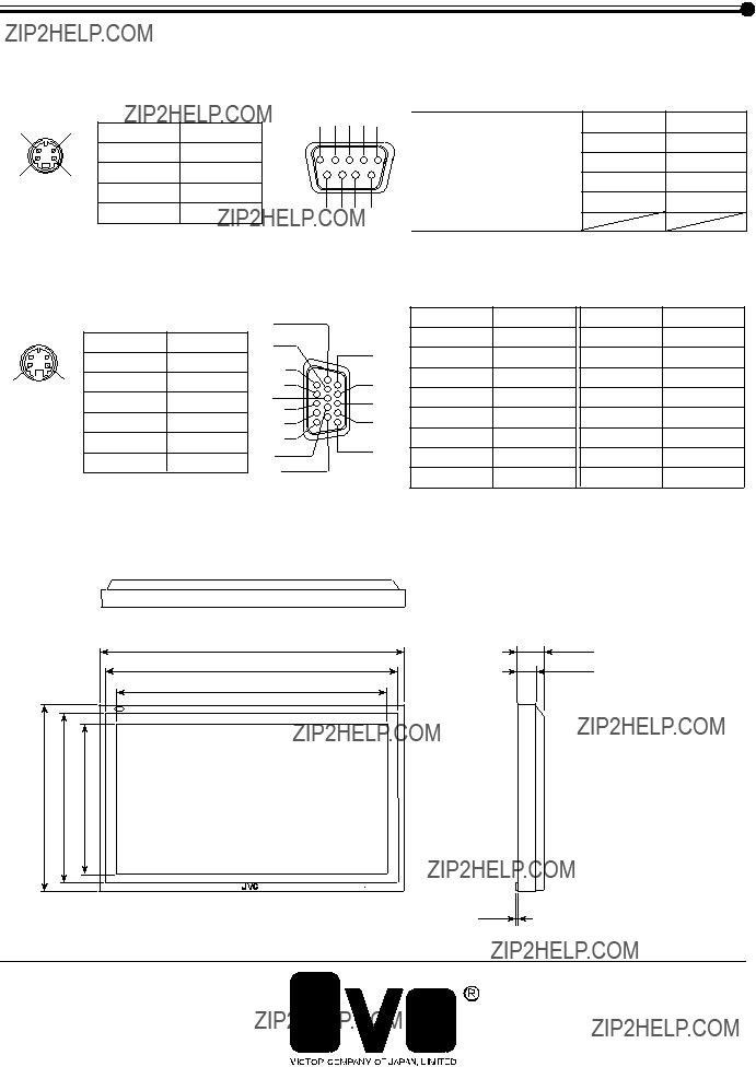
Specifications (Continued)
Pin assignment (Specifications for terminals)
??? Y/C terminal
???
This is a female type connector.
5 4 3 2 1
9 8 7 6
6 5
5
4
 3
3
2 1
Dimensions
Top view
Unit: mm
?? Registered Trademark owned by VICTOR COMPANY OF JAPAN, LTD.
42