External HDD Unit

VR-D0U INSTRUCTIONS

BEDIENUNGSANLEITUNG

INSTRUCTIONS

INSTRUCCIONES

ISTRUZIONI

Please read the following before getting started:

Thank you for purchasing this JVC product.

Before operating this unit, please read the instructions carefully to ensure the best possible performance.

For Customer Use:

Enter below the Serial No. which is located on the body.

Retain this information for future reference.

LST0419-001A

IMPORTANT SAFEGUARDS

1.Read all of these instructions.

2.Save these instructions for later use.

3.All warnings on the product and in the operating instructions should be adhered to.

4.Unplug this appliance system from the wall outlet before cleaning. Do not use liquid cleaners or aerosol cleaners. Use a damp cloth for cleaning.

5.Do not use attachments not recommended by the appliance manufacturer as they may cause hazards.

6.Do not use this appliance near water - for example, near a bathtub, washbowl, kitchen sink, or laundry tub, in a wet basement, or near a swimming pool, etc.

7. Do not place this appliance on an unstable cart, stand, or table. The appliance may fall, causing serious injury to a child or adult, and serious damage to the appliance. Use only with a cart or stand recommended by the manufacturer, or sold with the appliance.

Wall or shelf mounting should follow the manufacturer???s instructions, and should use a mounting kit approved by the manufacturer.

An appliance and cart combination should be moved with care. Quick stops, excessive force, and uneven surfaces may cause the appliance and cart combination to overturn.

8. Slots and openings in the cabinet and the back or bottom are provided for ventilation, and to insure reliable operation of the appliance and to protect it from overheating, these

openings must not be blocked or covered. The openings should never be blocked by placing the appliance on a bed, sofa, rug, or other similar surface. This appliance should never be placed near or over a radiator or heat register. This appliance should not be placed in a built-in installation such as a bookcase unless proper ventilation is provided.

9.This appliance should be operated only from the type of power source indicated on the marking label. If you are not sure of the type of power supplied to your home, consult your dealer or local power company. For appliance designed to operate from battery power, refer to the operating instructions.

10.This appliance system is equipped with a 3-wire grounding type plug (a plug having a third (grounding pin). This plug will only fit into a grounding-type power outlet. This is a safety feature. If you are unable to insert the plug into the outlet, contact your electrician to replace your obsolete outlet. Do not defeat the safety purpose of the grounding plug.

11.For added protection for this product during a lightning storm, or when it is left unattended and unused for long periods of time, unplug it from the wall outlet and disconnect the antenna or cable system. This will prevent damage to the product due to lightning and power-line surges.

12.Do not allow anything to rest on the power cord. Do not locate this appliance where the cord will be abused by persons walking on it.

13.Follow all warnings and instructions marked on the appliance.

14.Do not overload wall outlets and extension cords as this can result in fire or electric shock.

15.Never push objects of any kind into this appliance through cabinet slots as they may touch dangerous voltage points or short out parts that could result in a fire or electric shock. Never spill liquid of any kind on the appliance.

16.Do not attempt to service this appliance yourself as opening or removing covers may expose you to dangerous voltage or other hazards. Refer all servicing to qualified service personnel.

17.Unplug this appliance from the wall outlet and refer servicing to qualified service personnel under the following conditions:

a.When the power cord or plug is damaged or frayed.

b.If liquid has been spilled into the appliance.

c.If the appliance has been exposed to rain or water.

d.If the appliance does not operate normally by following the operating instructions. Adjust only those controls that are covered by the operating instructions as improper adjustment of other controls may result in damage and will often require extensive work by a qualified technician to restore the appliance to normal operation.

e.If the appliance has been dropped or the cabinet has been damaged.

f.When the appliance exhibits a distinct change in performance - this indicates a need for service.

18.When replacement parts are required, be sure the service technician has used replacement parts specified by the manufacturer that have the same characteristics as the original part. Unauthorized substitutions may result in fire, electric shock, or other hazards.

19.Upon completion of any service or repairs to this appliance, ask the service technician to perform routine safety checks to determine that the appliance is in safe operating condition.

I

SAFETY PRECAUTIONS (for USA & Canada)

The lightning flash with arrowhead symbol, within an equilateral triangle, is intended to alert the user to the presence of uninsulated ???dangerous voltage??? within the product???s enclosure that may be of sufficient magnitude to constitute a risk of electric shock to persons.

The exclamation point within an equilateral triangle is intended to alert the user to the presence of important operating and maintenance (servicing) instructions in the literature accompanying the appliance.

WARNING:

TO REDUCE THE RISK OF FIRE OR ELECTRIC

SHOCK, DO NOT EXPOSE THIS APPLIANCE TO

RAIN OR MOISTURE.

This unit should be used with 120 V to 240 V AC only.

CAUTION:

To prevent electric shocks and fire hazards, DO NOT use any other power source.

NOTE:

The rating plate (serial number plate) is on the rear of the unit.

INFORMATION:

This equipment has been tested and found to comply with the limits for a Class A digital device, pursuant to Part 15 of the FCC Rules. These limits are designed to provide reasonable protection against harmful interference when the equipment is operated in a commercial environment.

This equipment generates, uses, and can radiate radio frequency energy and, if not installed and used in accordance with the instruction manual, may cause harmful interference to radio communications.

Operation of this equipment in a residential area is likely to cause harmful interference in which case the user will be required to correct the interference at his own expense.

CAUTION:

CHANGES OR MODIFICATIONS NOT APPROVED BY JVC

COULD VOID USER???S AUTHORITY TO OPERATE THE

EQUIPMENT.

NOTE:

The rating plate (serial number plate) is on this unit.

WARNING:

TO REDUCE THE RISK OF FIRE OR ELECTRIC SHOCK, DO NOT

EXPOSE THIS APPLIANCE TO RAIN OR MOISTURE.

THIS DEVICE COMPLIES WITH PART 15 OF THE FCC RULES.

OPERATION IS SUBJECT TO THE FOLLOWING TWO

CONDITIONS: (1) THIS DEVICE MAY NOT CAUSE HARMFUL

INTERFERENCE, AND (2) THIS DEVICE MUST ACCEPT ANY

INTERFERENCE RECEIVED, INCLUDING INTERFERENCE THAT

MAY CAUSE UNDESIRED OPERATION.

Le symbole de l?????clair ?? l???int??rieur d???un triangle ??quilat??ral est destin?? ?? alerter l???utilisateur sur la pr??sence d???une ???tension dangereuse??? non isol??e dans le bo??tier du produit. Cette tension est suffisante pour provoquer l?????lectrocution de personnes.

Le point d???exclamation ?? l???int??rieur d???un triangle ??quilat??ral est destin?? ?? alerter l???utilisateur sur la pr??sence d???op??rations d???entretien importantes au sujet desquelles des renseignements se trouvent dans le manuel d???instructions.

* Ces symboles ne sont utilis??s qu???aux Etats-Unis.

AVERTISSEMENT:

POUR EVITER LES RISQUES D???INCENDIE OU

D???ELECTROCUTION, NE PAS EXPOSER

L???APPAREIL A L???HUMIDITE OU A LA PLUIE.

Ce magn??toscope ne doit ??tre utilis?? que sur du courant alternatif en 120 V ?? 240 V.

ATTENTION:

Afin d?????viter tout resque d???incendie ou d?????lectrocution, ne pas utiliser d???autres sources d???alimentation ??lectrique.

REMARQUE:

La plaque d???identification (num??ro de s??rie) se trouve sur le panneau arri??re de l???appareil.

INFORMATION (FOR CANADA)

RENSEIGNEMENT (POUR CANADA)

This Class A digital apparatus complies with Canadian ICES-003.

Cet appareil num??rique de la Classe A est conforme ?? la norme NMB-003 du Canada.

II

SAFETY PRECAUTIONS

IMPORTANT (In the United Kingdom)

Mains Supply (AC 230 V)

WARNING - THIS APPARATUS

MUST BE EARTHED

The wires in this mains lead are coloured in accordance with the following code;

GREEN-and-YELLOW : EARTH

BLUE : NEUTRAL

BROWN : LIVE

As the colours of the wires in the mains lead of this apparatus may not correspond with the coloured markings identifying the terminals in your plug, proceed as follows.

The wire which is coloured GREEN-AND-YELLOW must be connected to the terminal in the plug which is marked with the letter E or by the safety earth symbol or coloured GREEN or GREEN-AND-YELLOW.

The wire which is coloured BLUE must be connected to the terminal which is marked with the letter N or which is coloured BLACK. The wire which is coloured BROWN must be connected to the terminal which is marked with the letter L or coloured RED.

POWER SYSTEM

Connection to the mains supply

This unit operates on voltage of 120 V to 240 V AC, 50 Hz/60 Hz.

WARNING:

TO REDUCE THE RISK OF FIRE OR ELECTRIC

SHOCK, DO NOT EXPOSE THIS APPLIANCE TO RAIN

OR MOISTURE.

CAUTION

To prevent electric shock, do not open the cabinet. No user serviceable parts inside. Refer servicing to qualified service personnel.

Note:

The rating plate and the safety caution are on the rear and top of the unit.

Caution for AC Power Cord

FOR YOUR SAFETY PLEASE READ THE FOLLOWING TEXT CAREFULLY.

Appropriate AC Power Cord must be used in each local area.

III

SAFETY PRECAUTIONS

Information for Users on Disposal of Old Equipment

Attention:

This symbol is only valid in the European Union.

[European Union]

This symbol indicates that the electrical and electronic equipment should not be disposed as general household waste at its end-of-life. Instead, the product should be handed over to the applicable collection point for the recycling of electrical and electronic equipment for proper treatment, recovery and recycling in accordance with your national legislation.

By disposing of this product correctly, you will help to conserve natural resources and will help prevent potential negative effects on the environment and human health which could otherwise be caused by inappropriate waste handling of this product. For more information about collection point and recycling of this product, please contact your local municipal office, your household waste disposal service or the shop where you purchased the product.

Penalties may be applicable for incorrect disposal of this waste, in accordance with national legislation.

(Business users)

If you wish to dispose of this product, please visit our web page www.jvc-europe.com to obtain information about the take-back of the product.

[Other Countries outside the European Union]

If you wish to dispose of this product, please do so in accordance with applicable national legislation or other rules in your country for the treatment of old electrical and electronic equipment.

Dear Customer,

This apparatus is in conformance with the valid European directives and standards regarding electromagnetic compatibility and electrical safety.

European representatives of Victor Company of Japan Limited is:

JVC Technology Centre Europe GmbH P.O. Box 10 05 52

61145 Friedberg Germany

E-1

Getting Started

Main FeaturesContents

This is an HDD External Unit for Digital Video Recorders manu- factured by JVC

This HDD unit can be connected to the following DVR (Digital Video Recorders).

VR-509E

VR-N900U (scheduled for release December 2006)

*These units cannot be connected to any DVR or PC manufactured by any other company.

*When the VR-509E is connected to the VR-D0U, you may need a software update version for the DVR.

For more details, please contact the dealer where you purchased the unit or your nearest JVC dealer.

Getting Started

Contents . . . . . . . . . . . . . . . . . . . . . . . . . . . . . . . . . . . . . . E-2

PRECAUTIONS . . . . . . . . . . . . . . . . . . . . . . . . . . . . . . . . E-3

Part Names and Functions . . . . . . . . . . . . . . . . . . . . . . . . E-4

Preparation

Attaching to the Rack . . . . . . . . . . . . . . . . . . . . . . . . . . . . E-5 Connecting the Digital Video Recorder. . . . . . . . . . . . . . . E-5

Others

Specifications . . . . . . . . . . . . . . . . . . . . . . . . . . . . . . . . . . E-6

How to Read this Manual

???In the subsequent sections of this manual, this equipment shall be referred to as VR-D0U.

???The names of buttons used during operation are enclosed in [ ].

Example: MENU button ??? [MENU]

*All product names stated in this manual are trademarks or registered trademarks of their respective companies. Marks such as???, ?? and ?? are omitted in this manual.

E-2

PRECAUTIONS

???Place of storage and use

Please avoid storing or using this unit in the following places:

???Extremely hot or cold places beyond the allowable temperature for operation (5??C - 40??C).

???Humid or dry places beyond the allowable humidity range for operation (30% - 80% RH).

???Dusty or sandy places.

???Places exposed to oil, smoke or steam, such as the kitchen vicinity.

???Vibrating or unstable places.

???Places prone to condensation.

???Places that generates strong magnetic fields, e.g., transformer or motor.

???Places near devices that generate electric waves, e.g., transceiver or mobile phone.

???Places that generate radiation, X-rays or corrosive gases.

???Handling the unit

???Please do not place heavy objects on this unit, like a monitor or TV. Also, do not stack the VR-D0U units on top of each other.

???Please do not block the ventilation openings.

???Avoid violent shocks to the unit. Do not drop the unit.

???Maintaining the unit (Please turn off the power before performing maintenance work.)

Please wipe the unit with a soft cloth. Do not wipe it with thinner or benzene lest the surface melts or becomes dull. For stubborn stains, wipe first with a water-diluted neutral detergent and then wipe dry.

???Please use the supplied power cord. Using a different type or damaged cord may cause fire or electric shock.

???To save energy, be sure to turn off the system when not in use.

???Do not use the power cord supplied with this equipment on other devices.

???Do not stack up the equipment to prevent temperature within from rising.

???Do not insert foreign object into this unit as this may cause malfunction or electric shock.

Hard Disk Drive

The distance between the head and disk that read and write data on the hard disk drive (hereinafter known as the HDD) is a miniscule 0.02??m. Vibrations and physical shocks to the HDD may therefore result in the head coming into contact with the disk, producing dents and scratches to its surface. This will consequently prevent data from being read, and will result in disk crashes if use is continued. It is therefore necessary to handle the recorder with great care.

???The HDD is a consumable item. Replacement is recommended after 10000 hours of use (if use in a 25??C environment). For information on maintenance planning and costs, consult your nearest JVC dealer.

???It is recommended that an UPS (Uninterruptible Power Supply) is used when installing additional external hard disk drives to make sure the system remains stable.

???If a power failure occurs during formatting of HDD, disconnection, or when configuring or disabling mirroring, operation of the equipment may be disabled even if it is connected to the UPS.

???Please note that we will not provide compensation for any failure during recording or playback due to defects in this equipment or the HDD.

???Please note that recorded images will be erased when replacing hard disks. Note that there are cases where recorded images may be erased when software is upgraded.

???This equipment will automatically reset when minor data writing errors occur with the HDD or other device in this equipment???s system.

E-3

Getting Started

Part Names and Functions

Front View

Turns the power on and off. The POWER display lights green after the power is switched on.

2 [HDD ACCESS] display

Lights green while the HDD is being accessed. Never switch off the power while this display is lit.

Lights red if the HDD malfunctions. If this display lights contact the vendor where your purchased the unit or a JVC service representative for repairs.

4 [FAN ERR] display

Lights if the fan motor inside the unit malfunctions.

If this display lights contact the vendor where your purchased the unit or a JVC service representative for repairs.

Rear View

The connection point for the AC 120 V - 240 V power cord provided with the unit.

6 Cable clamp

The connection point for the provided cable and the DVR. You must use the special cable provided for the connection.

???Page E-5

Prevents the connection cable from disconnecting. ???Page E-5

E-4

Preparation

Attaching to the Rack

Use the rack mount fittings provided to attach the unit to the EIA rack.

When installing this unit in the EIA rack, contact your nearest JVC dealer.

Rack mount fitting

1.Remove the unit side screws.

Remove the front panel side screws (??4).

2.Attach the rack mount fittings.

Use the four screws (M4 ?? 10 mm) at ??? to fasten both sides of the unit.

3.Remove the feet (??4) from the bottom of the unit.

Loosen the fastening screws ??? and remove them.

4.Attach the unit to the rack.

Use the provided four screws (M5 ?? 11 mm) at ??? to fasten.

Caution

???Never place anything on top of a unit with a rack mount attached. This is to prevent unbalancing the rack, tipping it over, falling, and damaging the unit.

???When installing two or more units in a rack, leave space between the units about the size of one unit.

Connecting the Digital Video

Recorder

Before connecting the DVR and this unit, make sure that both are switched off.

For more details about the settings and operation of the DVR to be connected to this unit, please refer to the DVR operating instructions.

Connection cable (provided)

1.Connect this unit and DVR.

Use the provided cable to make the connection.

2.Fasten the connection cable.

Be sure to fasten the cable clamp (this prevents cable disconnection).

???Loosen the fastener screw of the cable clamp, then remove the cable clamp.

???Pass the connection cable through the cable clamp then fasten it to the unit.

3.Connect the power cord.

Connect the power cord plug to an AC 120 V - 240 V power outlet.

4.Switch this unit on.

5.Switch the DVR on.

6.Do the settings for the DVR.

Do the settings by following the procedures in the DVR operating instructions.

Note

???Never switch off the unit while the HDD ACCESS display is lit.

???Always make sure that the DVR is switched off before you switch on this power.

???Always power off the DVR before you switch off this unit. (The HDD ACCESS display may stay lit for about 30 seconds after the DVR has been turned off. You may turn off the power to the equipment because communication has ended.)

E-5

Others

Specifications

??? General

??? Accessories

Instructions. . . . . . . . . . . . . . . . . . . . . . . . . . . . . . . . . . . . 1 Power cord (For continental Europe, etc.: 2.5 m) . . . . . . 2 Power cord (For U.K. only: 2 m) . . . . . . . . . . . . . . . . . . . 1 Connection cable (1 m) . . . . . . . . . . . . . . . . . . . . . . . . . . 1 Rack mount fitting . . . . . . . . . . . . . . . . . . . . . . . . . . . . . . 2 Rack mount fitting fastener screws (M4 ?? 10 mm) . . . . . 4 Rack mount screws (M5 ?? 11 mm) . . . . . . . . . . . . . . . . . 4 Installation Date Label . . . . . . . . . . . . . . . . . . . . . . . . . . 3

???External Dimensions (Units: mm) 340 ?? 88 ?? 350 mm (W ?? H ?? D)

EXTERNAL HDD UNIT

VR-D0U

*Specifications and appearance of this unit are subject to change for improvement without prior notice.

Consumable Parts

The table below is a list of the consumable parts. The parts fee that accompanies these replacement and repair costs includes technical and official trip fees that are charged even during the guarantee period.

In order to support exchange and maintenance of consumable supplies, use the attached Installation date label. Enter the beginning date of use on the Installation date label and attach it to this equipment.

E-6

SICHERHEITSVORKEHRUNGEN

ACHTUNG:

UM DER GEFAHR VON BR??NDEN UND

ELEKTRISCHEN SCHL??GEN VORZUBEUGEN, DARF

DIESES GER??T WEDER DEM REGEN NOCH HOHER

FEUCHTIGKEIT AUSGESETZT WERDEN.

ACHTUNG

Um elektrische Schl??ge zu vermeiden, das Geh??use nie ??ffnen. Im Innern befinden sich keine Teile, die vom Benutzer gewartet werden k??nnen. ??berlassen Sie die Wartung qualifiziertem Service-Personal.

Sehr geehrter Kunde, sehr geehrte Kundin, dieses Ger??t stimmt mit den g??ltigen europ??ischen Richtlinien und Normen bez??glich elektromagnetischer Vertr??glichkeit und elektrischer Sicherheit ??berein.

Die europ??ische Vertretung f??r die Victor Company of Japan, Limited ist:

JVC Technology Centre Europe GmbH Postfach 10 05 52

61145 Friedberg Deutschland

Benutzerinformationen zur Entsorgung alter Ger??te

Hinweis:

Dieses Symbol ist nur in der Europ??ischen Union g??ltig.

[Europ??ische Union]

Dieses Symbol zeigt an, dass das elektrische bzw. elektronische Ger??t nicht als normaler Haushaltsabfall entsorgt werden soll. Stattdessen sollte das Produkt zur fachgerechten Entsorgung, Weiterverwendung und Wiederverwertung in ??bereinstimmung mit der Landesgesetzgebung einer entsprechenden Sammelstelle f??r das Recycling elektrischer und elektronischer Ger??te zugef??hrt werden.

Die korrekte Entsorgung dieses Produkts dient dem Umweltschutz und verhindert m??gliche Sch??den f??r die Umwelt und die menschliche Gesundheit, welche durch unsachgem????e Behandlung des Produkts auftreten k??nnen. Weitere Informationen zu Sammelstellen und dem Recycling dieses Produkts erhalten Sie bei Ihrer Gemeindeverwaltung, Ihrem ??rtlichen Entsorgungsunternehmen oder in dem Gesch??ft, in dem Sie das Produkt gekauft haben.

F??r die nicht fachgerechte Entsorgung dieses Abfalls k??nnen gem???? der Landesgesetzgebung Strafen ausgesprochen werden.

(Gesch??ftskunden)

Wenn Sie dieses Produkt entsorgen m??chten, besuchen Sie bitte unsere Webseite www.jvc-europe.com, um Informationen zur R??cknahme des Produkts zu erhalten.

[Andere L??nder au??erhalb der Europ??ischen Union]

Wenn Sie dieses Produkt entsorgen m??chten, halten Sie sich dabei bitte an die entsprechenden Landesgesetze und andere Regelungen in Ihrem Land zur Behandlung elektrischer und elektronischer Ger??te.

Erkl??rung zum Rauschen (f??r die Bundesrepublik Deutschland):

Maschinenl??rminformations-Verordunung 3. GPSGV, 06.01.2004: Der h??chste

Schalldruckpegel betr??gt 70 dB(A) oder weniger gem???? EN ISO 7779

Hinweis zum Netzanschlu??kabel

Zu Ihrer Sicherheit lesen Sie bitte das folgende sorgf??ltig.

Verwenden Sie ausschlie??lich ein in Ihrem Land zul??ssiges Netzkabel.

G-1

Einleitung

HauptmerkmaleInhalt

Dieses Ger??t ist ein externes Festplattenlaufwerk f??r digitale Videorekorder, die von JVC hergestellt wurden.

Dieses Festplattenlaufwerk kann an die folgenden digitalen Videorekorder (DVR) angeschlossen werden.

VR-509E

VR-N900U (geplante Markteinf??hrung: Dezember 2006)

*Diese Ger??te k??nnen nicht an digitale Videorekorder oder PCs von anderen Firmen angeschlossen werden.

*Wenn das Modell VR-509E an das Modell VR-D0U angeschlossen wird, m??ssen Sie die Software-Version des digitalen Videorekorders aktualisieren.

Weitere Einzelheiten erhalten Sie im Gesch??ft, in dem Sie Ihr Ger??t gekauft haben, oder bei Ihrem n??chsten JVC- Fachh??ndler.

Einleitung

Inhalt. . . . . . . . . . . . . . . . . . . . . . . . . . . . . . . . . . . . . . . . .G-2 VORSICHTSHINWEISE. . . . . . . . . . . . . . . . . . . . . . . . . .G-3 Bezeichnungen und Funktionen der Teile . . . . . . . . . . . . . .G-4

Vorbereitung

Befestigung am Rack . . . . . . . . . . . . . . . . . . . . . . . . . . . .G-5 Anschlie??en des digitalen Videorekorders . . . . . . . . . . . .G-5

Sonstiges

Technische Daten . . . . . . . . . . . . . . . . . . . . . . . . . . . . . . .G-6

Wie diese Bedienungsanleitung zu lesen ist

???In den nachfolgenden Abschnitten dieser Bedienungsanleitung wird dieses Ger??t als VR- D0U bezeichnet.

???Die Bezeichnungen der Tasten, die bei der Bedienung verwendet werden, sind in eckigen Klammern ([ ]) angef??hrt.

Beispiel: Men??-Taste ??? [MENU]

*Alle in der Bedienungsanleitung angef??hrten Produktnamen sind Warenzeichen oder eingetragene Warenzeichen der jeweiligen Firmen.

Bezeichnungen wie???, ?? und ?? werden in dieser Bedienungsanleitung ausgelassen.

G-2

VORSICHTSHINWEISE

???Aufbewahrungs- und Verwendungsorte

Vermeiden Sie die folgenden Orte, um das Ger??t aufzubewahren oder zu verwenden:

???Besonders hei??e oder kalte Orte, deren Temperatur au??erhalb des zul??ssigen Temperaturbereichs von 5??C bis 40??C liegt.

???Feuchte oder trockene Orte, deren Luftfeuchtigkeit au??erhalb des zul??ssigen Bereichs von 30% bis 80% relative Feuchte liegt.

???Staubige oder sandige Orte.

???Orte mit viel ??l, Rauch oder Dampf, beispielsweise die Umgebung einer K??che.

???Orte, die Ersch??tterungen ausgesetzt oder unstabil sind.

???Orte, an denen sich leicht Kondensation bilden kann.

???Orte, die starke Magnetfelder erzeugen, z. B. die Umgebung von Transformatoren oder Motoren.

???Orte in der Umgebung von Ger??ten, die starke Elektrowellen erzeugen, z. B. Transceiver oder Handys.

???Orte, die Strahlungen, R??ntgenstrahlen oder korrosive Gase erzeugen.

???Handhabung des Ger??ts

???Stellen Sie keine schweren Gegenst??nde, beispielsweise einen Bildschirm oder Fernsehen, auf dieses Ger??t. Stapeln Sie auch nicht mehrere VR- D0U-Modelle ??bereinander.

???Blockieren Sie nicht die Entl??ftungs??ffnungen.

???Setzen Sie das Ger??t keinen starken St????en aus. Lassen Sie das Ger??t nicht fallen.

???Wartung des Ger??ts (Schalten Sie die Stromversorgung aus, bevor Sie Wartungsarbeiten durchf??hren.)

Wischen Sie das Ger??t mit einem weichen Tuch ab. Wischen Sie es nicht mit Verd??nner oder Benzol ab, da anderenfalls die Geh??useoberfl??che besch??digt oder matt werden kann. Bei hartn??ckigen Flecken wischen Sie das Ger??t zuerst mit einem Tuch ab, das in einem neutralen Reinigungsmittel angefeuchtet wurde, und wischen Sie das Ger??t dann trocken.

???Bitte verwenden Sie das mitgelieferte Netzkabel. Bei Verwendung eines anderen bzw. eines besch??digten Netzkabels besteht Brand- oder Stromschlaggefahr.

???Um Strom zu sparen, schalten Sie das Ger??t aus, wenn Sie es nicht verwenden.

???Verwenden Sie das Netzkabel dieses Ger??ts nicht f??r andere Ger??te.

???Stapeln Sie dieses Ger??t nicht, damit im Ger??teinneren kein Temperaturstau auftritt.

???F??hren Sie keine Fremdk??rper in das Ger??t ein, da anderenfalls die Gefahr einer Funktionsst??rung bzw. eines Stromschlags besteht.

Festplattenlaufwerk

Der Abstand zwischen dem Kopf und der Platte, die die Daten lesen und auf dem Festplattenlaufwerk (HDD) aufzeichnen, betr??gt nur 0,02 ??m. Ersch??tterungen und St????e, denen das Festplattenlaufwerk ausgesetzt ist, k??nnen dazu f??hren, dass der Kopf mit der Platte in Ber??hrung kommt, so dass auf ihrer Oberfl??che Beulen oder Kratzer entstehen. Dies kann dazu f??hren, dass beim Lesen der Daten Probleme auftreten, so dass die Platte abst??rzt, falls der Betrieb fortgesetzt wird. Daher sollten Sie beim Umgang mit dem Rekorder besonders vorsichtig sein.

???Das Festplattenlaufwerk ist ein Verbrauchsteil. Wir empfehlen, das Festplattenlaufwerk nach jeweils 10 000 Betriebsstunden (in einer Umgebungstemperatur von 25??C) auszutauschen. Weitere Informationen zur Planung der Wartung und deren Kosten erhalten Sie bei Ihrem n??chsten JVC-Fachh??ndler.

???Wir empfehlen, eine unterbrechungsfreie Stromversorgung (USV) zu verwenden, wenn Sie zus??tzliche externe Festplattenlaufwerke anschlie??en, damit die Anlage stabil bleibt.

???Falls beim Formatieren des Festplattenlaufwerks, seiner Abtrennung oder Konfiguration bzw. der Deaktivierung des Plattenspiegelungsbetriebs ein Stromausfall auftritt, kann der Betrieb des Ger??ts beeintr??chtigt werden, selbst wenn es an eine unterbrechungsfreie Stromversorgung angeschlossen ist.

???Beachten Sie bitte, dass wir keinen Schadenersatz f??r Ger??teversagen w??hrend der Aufnahme oder Wiedergabe anbieten, die auf Defekte in diesem Ger??t oder dem Festplattenlaufwerk zur??ckzuf??hren sind.

???Beachten Sie bitte, dass die aufgezeichneten Bilder beim Austauschen von Festplatten gel??scht werden. Beachten Sie bitte, dass die aufgezeichneten Bilder u. U. auch beim Aktualisieren der Software gel??scht werden k??nnen.

???Dieses Ger??t f??hrt automatisch eine R??cksetzung durch, wenn kleinere Datenschreibfehler auf der Festplatte oder anderen Ger??ten dieser Anlage auftreten.

G-3

Einleitung

Bezeichnungen und

Funktionen der Teile

1 Netzschalter [POWER]

Dient zum Ein- und Ausschalten des Ger??ts. Die Anzeige POWER leuchtet gr??n, nachdem das Ger??t eingeschaltet wurde.

Falls diese Anzeige leuchtet, wenden Sie sich an das Gesch??ft, in dem Sie das Ger??t erworben haben, oder eine JVC-Kundendienststelle, um das Ger??t reparieren zu lassen.

2 Anzeige [HDD ACCESS]

Leuchtet gr??n, wenn ein Zugriff auf das Festplattenlaufwerk erfolgt. Schalten Sie das Ger??t nie aus, w??hrend diese Anzeige leuchtet.

3 Anzeige [HDD ERR]

Leuchtet rot, wenn eine Funktionsst??rung des Festplattenlaufwerks vorliegt.

4 Anzeige [FAN ERROR]

Leuchtet, wenn eine Funktionsst??rung des Gebl??semotors im Ger??t vorliegt.

Falls diese Anzeige leuchtet, wenden Sie sich an das Gesch??ft, in dem Sie das Ger??t erworben haben, oder eine JVC-Kundendienststelle, um das Ger??t reparieren zu lassen.

Schlie??en Sie das mit diesem Ger??t mitgelieferte Kabel f??r Netzstrom mit einer Spannung von 120 V bis 240 V hier an.

6 Kabelklemme

Verhindert, dass das Anschlusskabel abgetrennt wird. ???Seite G-5

Verwenden Sie das mit diesem Ger??t mitgelieferte Kabel, um den digitalen Videorekorder an diese Buchse anzuschlie??en. Sie m??ssen das f??r den Anschluss vorgesehene Spezialkabel verwenden.

???Seite G-5

G-4

Vorbereitung

Verwenden Sie die mitgelieferten Rack-Montage- anschlussst??cke, um das Ger??t am EIA-Rack zu befestigen. Wenden Sie sich an den n??chsten JVC-Fachh??ndler, um das Ger??t am EIA-Rack zu befestigen.

Rack-Montage- anschlussst??cke

1.Entfernen Sie die Seitenschrauben des Ger??ts.

Entfernen Sie die Seitenschrauben der Frontplatte (x4).

2.Befestigen Sie die Rack-Montage- anschlussst??cke.

Verwenden Sie die vier Schrauben (M4 x 10 mm) von Schritt ???, um beide Seiten des Ger??ts zu befestigen.

3.Entfernen Sie die F????e (x4) von der Unterseite des Ger??ts.

Lockern Sie die Befestigungsschrauben ???, und entfernen Sie sie dann.

4.Befestigen Sie das Ger??t am Rack.

Verwenden Sie die vier Schrauben (M5 x 11 mm) von Schritt ???, um das Ger??t zu befestigen.

Vorsicht

???Stellen Sie nie Gegenst??nde auf ein Ger??t mit angebrachten Rack-Montageanschlussst??cken. Sie verhindern dadurch, dass das Rack nicht das Gleichgewicht verliert, umf??llt und das Ger??t besch??digt.

???Achten Sie bei der Installation von zwei oder mehreren Ger??ten in einem Rack darauf, dass zwischen den Ger??ten ausreichend Platz bleibt, und zwar jeweils entsprechend etwa der Gr????e eines Ger??ts.

Bevor Sie den digitalen Videorekorder mit dem Hauptger??t verbinden, vergewissern Sie sich, dass beide Ger??te ausgeschaltet sind.

Weitere Einzelheiten zu den Einstellungen und der Bedienung des digitalen Videorekorders, der an dieses Ger??t angeschlossen werden soll, entnehmen Sie bitte der Bedienungsanleitung des digitalen Videorekorders.

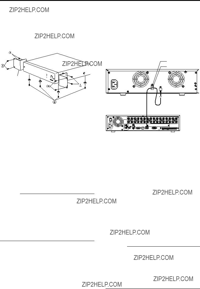
Anschlusskabel (mitgeliefert)

1.Verbinden Sie dieses Ger??t mit dem digitalen Videorekorder.

Verwenden Sie das f??r den Anschluss vorgesehene Spezialkabel.

2.Befestigen Sie das Anschlusskabel.

Befestigen Sie die Kabelklemme (dadurch wird verhindert, dass das Kabel abgetrennt wird).

???Locken Sie die Befestigungsschraube des Kabelklemme, und nehmen Sie die Kabelklemme

dann ab.

???F??hren Sie das Anschlusskabel durch die Kabelklemme ein, und befestigen Sie es dann am Ger??t.

3.Schlie??en Sie das Netzkabel an.

Stecken Sie den Netzkabelstecker in eine Steckdose, die Strom mit einer Spannung von 120 V bis 240 V f??hrt.

4.Schalten Sie dieses Ger??t ein.

5.Schalten Sie den digitalen Videorekorder ein.

6.F??hren Sie die Einstellungen des digitalen Videorekorders durch.

F??hren Sie diese Einstellungen durch, indem Sie die Verfahren in der Bedienungsanleitung des digitalen Videorekorders befolgen.

Hinweise

???Schalten Sie das Ger??t nie aus, w??hrend die Anzeige [HDD ACCESS] leuchtet.

???Vergewissern Sie sich immer, dass der digitale Videorekorder ausgeschaltet ist, bevor Sie dieses Ger??t einschalten.

???Schalten Sie immer zuerst den digitalen Videorekorder aus, bevor Sie dieses Ger??t ausschalten. (Die Anzeige [HDD ACCESS] bleibt ca. 30 Sekunden lang leuchten, nachdem der digitale Videorekorder ausgeschaltet wurde. Sie k??nnen das Ger??t dann ausschalten, da die Kommunikation beendet wurde.)

G-5

Sonstiges

Technische Daten

??? Allgemein

??? Zubeh??r

Bedienungsanleitung . . . . . . . . . . . . . . . . . . . . . . . . . . . 1 Netzkabel (F??r Kontinentaleuropa usw.: 2,5 m). . . . . . . . 2 Netzkabel (nur f??r Gro??britannien: 2 m) . . . . . . . . . . . . .1 Anschlusskabel (1 m) . . . . . . . . . . . . . . . . . . . . . . . . . . . 1 Rack-Montageanschlussst??ck . . . . . . . . . . . . . . . . . . . .2 Befestigungsschrauben (M4 x 10 mm) f??r die Rack-Montageanschlussst??cke . . . . . . . . . . . . . . . . . . . .4 Rack-Montageschrauben (M5 x 11 mm) . . . . . . . . . . . . .4 Installationsdatumsaufkleber . . . . . . . . . . . . . . . . . . . . . . 3

???Au??enabmessungen (Einheit: mm) 340 x 88 x 350 mm (B x H x T)

EXTERNAL HDD UNIT

VR-D0U

*??nderungen der technischen Daten und der ??u??ere Aufmachung des Ger??ts jederzeit ohne vorherige Ank??ndigung vorbehalten.

Verbrauchsteile

Die untenstehende Tabelle zeigt eine Liste der Verbrauchsteile. Die neben den Ersatzteilen aufgelisteten Preise umfassen die technischen Kosten und die Versandkosten, die selbst w??hrend der Garantieperiode berechnet werden.

Um den Austausch und die Wartung der Verbrauchsteile zu unterst??tzen, verwenden Sie den angebrachten Installationsdatumsaufkleber. Geben Sie das Anfangsdatum des Gebrauchs auf dem Installationsdatumsaufkleber ein, und befestigen Sie den Aufkleber an diesem Ger??t.

G-6

PR??CAUTIONS DE S??CURIT??

Cher(e) client(e),

Cet appareil est conforme aux directives et normes europ??ennes en vigueur concernant la compatibilit?? ??lectromagn??tique et ?? la s??curit?? ??lectrique.

Repr??sentant europ??en de la soci??t?? Victor Company of Japan, Limited : JVC Technology Centre Europe GmbH

Postfach 10 05 52

61145 Friedberg Allemagne

Informations relatives ?? l?????limination des appareils usag??s, ?? l???fintention des utilisateurs

Attention :

Ce symbole n???est reconnu que dans l???Union europ??enne.

[Union europ??enne]

Lorsque ce symbole figure sur un appareil ??lectrique et ??lectronique, cela signifie qu???il ne doit pas ??tre ??limin?? en tant que d??chet m??nager ?? la fin de son cycle de vie. Le produit doit ??tre port?? au point de pr??- collecte appropri?? au recyclage des appareils ??lectriques et ??lectroniques pour y subir un traitement, une r??cup??ration et un recyclage, conform??ment ?? la l??gislation nationale.

En ??liminant correctement ce produit, vous contriburez ?? la conservation des ressources naturelles et ?? la pr??vention des ??ventuels effets n??gatifs sur l???environnement et la sant?? humaine, pouvant ??tre dus ?? la manipulation inappropri??e des d??chets de ce produit. Pour plus d???informations sur le point de pr??-collecte et le recyclage de ce produit, contactez votre mairie, le service d?????vacuation des ordures m??nag??res ou le magasin dans lequel vous avez achet?? le produit.

Des amendes peuvent ??tre inflig??es en cas d?????limination incorrecte de ce produit, conform??ment ?? la l??gislation nationale.

(Utilisateurs professionnels)

Si vous souhaitez ??liminer ce produit, visitez notre page Web www.jvc-europe.com afin d???obtenir des informations sur sa r??cup??ration.

[Pays ne faisant pas partie de l???Union europ??enne]

Si vous souhaitez ??liminer ce produit, faites-le conform??ment ?? la l??gislation nationale ou autres r??gles en vigueur dans votre pays pour le traitement des appareils ??lectriques et ??lectroniques usag??s.

F-1

Pour commencer

Cet appareil est une Unit?? HDD Externe pr??vue pour les enregistreurs vid??o num??riques fabriqu??s par JVC

Cette unit?? HDD peut ??tre connect??e aux enregistreurs vid??o num??riques (DVR) indiqu??s ci-dessous.

VR-509E

VR-N900U (lancement pr??vu pour D??cembre 2006)

*Cet appareil ne peut pas ??tre connect?? ?? un DVR ou PC d???une autre marque.

*Quand le VR-509E est connect?? au VR-D0U, une version mise ?? jour du logiciel peut s???av??rer n??cessaire pour le DVR. Pour plus de d??tails, pri??re de contacter le revendeur chez qui on a achet?? l???appareil ou le revendeur JVC le plus proche.

Pour commencer

Sommaire . . . . . . . . . . . . . . . . . . . . . . . . . . . . . . . . . . . . . F-2 PR??CAUTIONS . . . . . . . . . . . . . . . . . . . . . . . . . . . . . . . . F-3 Nomenclature et fonctions . . . . . . . . . . . . . . . . . . . . . . . . F-4

Pr??paration

Fixation ?? un b??ti . . . . . . . . . . . . . . . . . . . . . . . . . . . . . . . F-5 Connexion de l???enregistreur vid??o num??rique . . . . . . . . . F-5

Divers

Caract??ristiques techniques . . . . . . . . . . . . . . . . . . . . . . . F-6

Comment lire ce manue

???Dans la suite de ce manuel, ce mat??riel est appel?? VR-D0U.

???Les noms des touches utilis??es pour les diverses op??rations sont indiqu??s entre [ ].

Exemple: Touche MENU ??? [MENU]

*Tous les noms de produit mentionn??s dans ce manuel sont des marques de fabrique ou des marques d??pos??es de leurs soci??t??s respectives.

Dans ce manuel, les marques telles que???, ?? et ?? sont omises.

F-2

PR??CAUTIONS

???Endroit de rangement et d???utilisation

Pri??re d?????viter de ranger ou d???utiliser cet appareil dans les endroits suivants:

???Endroits extr??mement froids ou chauds o?? la temp??rature est hors de la plage d???utilisation admissible (5??C - 40??C).

???Endroits humides ou secs o?? l???h???umidit?? relative est

hors de la plage d???utilisation admissible (30% - 80% HR).

???Endroits poussi??reux ou sablonneux.

???Endroits expos??s ?? de l???huile, de la fum??e ou de la vapeur, comme dans une cuisine ou ?? proximit??.

???Endroits instables ou soumis ?? des vibrations.

???Endroits sujets ?? de la condensation.

???Endroits qui g??n??rent de puissants champs magn??tiques, par ex., transformateur ou moteur ??lectrique.

???Endroits ?? proximit?? d???appareils qui g??n??rent des ondes ??lectromagn??tiques, par ex., ??metteur-r??cepteur ou t??l??phone portable.

???Endroits o?? des radiations, des rayons X ou des gaz corrosifs sont g??n??r??s.

???Manipulation de l???appareil

???Pri??re de ne pas poser d???objet lourd, tel qu???un moniteur ou un t??l??viseur, sur cet appareil. En outre, ne pas empiler plusieurs appareils VR-D0U.

???Pri??re de ne pas obstruer les ouvertures de ventilation.

???Eviter de soumettre l???appareil ?? des chocs. Ne pas le laisser tomber.

???Entretien de l???appareil (Pri??re de couper l???alimentation avant de proc??der ?? toute op??ration d???entretien.)

Pri??re d???essuyer l???appareil avec un chiffon doux. Ne jamais utiliser du diluant ou du benz??ne pour le nettoyer; cela pourrait faire fondre ou ternir la surface. Pour les taches rebelles, essuyer d???abord avec un chiffon l??g??rement imbib?? d???un d??tergent neutre dilu?? ?? l???eau, puis avec un chiffon sec.

???Pri??re d???utiliser le cordon d???alimentation fourni. L???utilistion d???un cordon endommag?? ou de type diff??rent peut donner lieu ?? un incendie ou un choc ??lectrique.

???Pour ??conomiser l?????nergie, ne pas oublier d?????teindre le syst??me quand il n???est pas utilis??.

???Ne pas utiliser le cordon d???alimentation fourni avec cet appareil sur un autre mat??riel.

???Pour ??viter toute augmentation anormale de la temp??rature interne des divers appareils, ne pas les empiler.

???Ne pas introduire de corps ??tranger dans cet appareil; cela pourrait entra??ner un mauvais fonctionnement ou un choc ??lectrique.

Disque dur

Le minuscule espace entre le disque dur (aussi appel?? HDD) et la t??te qui lit et ??crit les donn??es sur ce disque est de 0,02 ??m. Si le disque dur est soumis ?? des vibrations ou des chocs, cela peut entra??ner un contact de la t??te avec le disque, donnant lieu ?? des entailles et des rayures sur la surface de celui-ci. Ceci emp??che alors la lecture des donn??es, et peut provoquer un endommagement irr??m??diable du disque. Il est donc n??cessaire de manipuler l???enregistreur avec une tr??s grande attention.

???Le disque dur est un ??l??ment consommable. Il est conseill?? de le remplacer apr??s 10 000 heures d???utilisation (sous une temp??rature ambiante de 25??C). Pour les informations concernant les pr??visions et les frais d???entretien, consulter le revendeur JVC le plus proche.

???Il est conseill?? d???utiliser une alimentation ininterruptible (UPS) lors de l???installation de disques durs externes suppl??mentaires, cela permettra d???assurer la stabilit?? du syst??me.

???Si une panne d???alimentation se produit pendant le formatage du disque dur, la d??connexion, ou lors de la configuration ou de la d??sactivation du mode miroir, le fonctionnement du mat??riel peut ??tre interrompu m??me s???il est connect?? ?? une UPS.

???Pri??re de noter que nous n???accordons aucune indemnisation pour toute panne pendant l???enregistrement ou la lecture du fait de d??fauts dans ce mat??riel ou le disque dur.

???Pri??re de noter que les images enregistr??es seront effac??es lors du remplacement des disques durs. Noter que dans certains cas les images enregistr??es peuvent ??tre effac??es lors de la mise ?? niveau du logiciel.

???Ce mat??riel est automatiquement r??initialis?? quand des erreurs mineures d?????criture de donn??es se produisent avec le disque dur ou tout autre appareil se trouvant dans le syst??me.

F-3

Pour commencer

Nomenclature et fonctions

Vue de face

Permet d???allumer et d?????teindre l???appareil. L???affichage POWER s???allume en vert quand l???appareil est allum??.

2 Affichage [HDD ACCESS]

S???allume en vert quand il y a un acc??s au disque dur.

Ne jamais ??teindre l???appareil quand cet affichage est 4 allum??.

Affichage [HDD ERR]

S???allume en rouge en cas de mauvais fonctionnement du disque dur. Si cet affichage s???allume, contacter le revendeur chez qui on a achet?? l???appareil ou un agent de service JVC pour le faire r??parer.

Affichage [FAN ERR]

S???allume en cas de mauvais fonctionnement du moteur de ventilateur situ?? ?? l???int??rieur de l???appareil. Si cet affichage s???allume, contacter le revendeur chez qui on a achet?? l???appareil ou un agent de service JVC pour le faire r??parer.

Vue de dos

Point de connexion pour le cordon d???alimentation CA 120 V - 240 V fourni avec l???appareil.

6 Bride de c??ble

Emp??che le c??ble de connexion de se d??brancher. ???Page F-5

DVR)

Point de connexion pour le c??ble fourni et le DVR. Pour la connexion, il faut utiliser le c??ble sp??cial fourni. ???Page F-5

F-4

Pr??paration

Fixation ?? un b??ti

Pour fixer l???appareil ?? un b??ti EIA, utiliser les ferrures de fixation fournies.

Pour l???installation de cet appareil dans un b??ti EIA, contacter le revendeur JVC le plus proche.

Ferrure de fixation sur b??ti

1.Enlever les vis lat??rales de l???appareil.

Enlever les vis lat??rales du panneau avant (??4).

2.Monter les ferrures de fixation sur b??ti.

Utiliser les quatre vis (M4 ?? 10 mm) en ??? pour fixer les deux c??t??s de l???appareil.

3.Enlever les pieds (??4) de la base de l???appareil.

Desserrer les vis de fixation ??? et les enlever.

4.Fixer l???appareil au b??ti.

Utiliser les quatre vis fournies (M5 ?? 11 mm) en ??? pour fixer.

Attention

???Ne jamais rien poser sur un appareil fix?? ?? un b??ti. Le b??ti pourrait ??tre d??s??quilibr??, se renverser, tomber, et endommager l???appareil.

???Lors de l???installation de deux appareils ou plus dans un b??ti, laisser un espace d???environ la taille d???un appareil entre eux.

Connexion de l???enregistreur vid??o num??rique

Avant de connecter le DVR et l???appareil, s???assurer que les deux sont ??teints.

Pour plus de d??tails sur les r??glages et l???utilisation du DVR ?? connecter ?? cet appareil, pri??re de se r??f??rer au mode d???emploi du DVR.

Vis de fixation de bride de c??ble

C??ble de connexion (fourni)

Enregistreur vid??o num??rique A la borne s??rie

1.Connecter cet appareil et le DVR.

Utiliser le c??ble fourni pour faire la connexion.

2.Attacher le c??ble de connexion.

Veiller ?? fixer la bride de c??ble (cela emp??che la d??connexion du c??ble).

???Desserrer la vis de fixation de la bride de c??ble, puis

enlever la bride de c??ble.

???Faire passer le c??ble de connexion ?? travers la bride de c??ble puis fixer cette bride ?? l???appareil.

3.Brancher le cordon d???alimentation.

Brancher le cordon d???alimentation ?? une prise CA 120 V - 240 V.

4.Allumer cet appareil.

5.Allumer le DVR.

6.Faire les r??glages pour le DVR.

Faire les r??glages en proc??dant comme d??crit dans le mode d???emploi du DVR.

Remarque

???Ne jamais ??teindre l???appareil lorsque l???affichage HDD ACCESS est allum??.

???Avant d???allumer cet appareil, toujours s???assurer que le DVR est ??teint.

???Avant d?????teindre cet appareil, toujours ??teindre le DVR. (Une fois que le DVR est ??teint, l???affichage HDD ACCESS peut rester allum?? pendant environ 30 secondes. Du fait que la communication est termin??e, vous pouvez ??teindre l???appareil.)

F-5

Divers

Caract??ristiques techniques

??? G??n??rales

??? Accessoires

Mode d???emploi . . . . . . . . . . . . . . . . . . . . . . . . . . . . . . . . . 1 Cordon d???alimentation

(Pour Europe continentale, etc.: 2,5 m) . . . . . . . . . . . . . . 2 Cordon d???alimentation

(Pour Royaume-Uni seulement: 2 m) . . . . . . . . . . . . . . . 1 C??ble de connexion (1 m) . . . . . . . . . . . . . . . . . . . . . . . .1 Ferrure de fixation sur b??ti . . . . . . . . . . . . . . . . . . . . . . . . 2 Vis de fixation de ferrure de fixation sur b??ti

(M4 ?? 10 mm) . . . . . . . . . . . . . . . . . . . . . . . . . . . . . . . . . 4 Vis de fixation sur b??ti (M5 ?? 11 mm) . . . . . . . . . . . . . . .4 Etiquette de date d???installation . . . . . . . . . . . . . . . . . . . . 3

???Dimensions externes (Unit??: mm) 340 ?? 88 ?? 350 mm (L ?? H ?? P)

EXTERNAL HDD UNIT

VR-D0U

*Les caract??ristiques techniques et l???aspect ext??rieur de l???appareil sont modifiables sans pr??avis.

El??ments consommables

Le tableau ci-dessous est une liste des ??l??ments consommables. Le prix des pi??ces qui accompagne ces frais de remplacement et de r??paration comprend les prix de l???intervention technique et du transport qui sont factur??s m??me pendant la p??riode de garantie.

Pour confirmer l?????change et l???entretien des ??l??ments consommables, utiliser l?????tiquette de date d???installation fournie. Inscrire la date de d??but de l???utilisation sur l?????tiquette de date d???installation et coller cette ??tiquette sur l???appareil.

F-6

PRECAUCIONES DE SEGURIDAD

Apreciado cliente,

Este aparato cumple con las normativas y normas europeas respecto a la seguridad el??ctrica y a la compatibilidad electromagn??tica.

El representante europeo de Victor Company of Japan, Limited es: JVC Technology Centre Europe GmbH

Postfach 10 05 52

61145 Friedberg Alemania

Informaci??n para los usuarios sobre la eliminaci??n de equipos usados

Atenci??n:

Este s??mbolo s??lo es v??lido en la Uni??n Europea.

[Uni??n Europea]

Este s??mbolo indica que los aparatos el??ctricos y electr??nicos no deben desecharse junto con la basura dom??stica al final de su vida ??til. El producto deber?? llevarse al punto de recogida correspondiente para el reciclaje y el tratamiento adecuado de equipos el??ctricos y electr??nicos de conformidad con la legislaci??n nacional.

Si desecha el producto correctamente, estar?? contribuyendo a conservar los recursos naturales y a prevenir los posibles efectos negativos en el medio ambiente y en la salud de las personas que podr??a causar el tratamiento inadecuado del producto desechado. Para obtener m??s informaci??n sobre el punto de recogida y el reciclaje de este producto, p??ngase en contacto con su oficina municipal, su servicio de recogida de basura dom??stica o la tienda en la que haya adquirido el producto.

De acuerdo con la legislaci??n nacional, podr??an aplicarse multas por la eliminaci??n incorrecta de estos desechos.

(Empresas)

Si desea desechar este producto, visite nuestra p??gina Web www.jvc-europe.com para obtener informaci??n acerca de la retirada del producto.

[Otros pa??ses no pertenecientes a la Uni??n Europea]

Si desea desechar este producto, h??galo de conformidad con la legislaci??n nacional vigente u otras normativas de su pa??s para el tratamiento de equipos el??ctricos y electr??nicos usados.

S-1

Introducci??n

Principales funciones Contenido

??sta es una Unidad HDD Externa para Grabadoras de V??deo Digitales fabricadas por JVC

Esta unidad HDD puede conectarse a las siguientes grabadoras DVR (Grabadoras de V??deo Digitales).

VR-509E

VR-N900U (lanzamiento programado para diciembre de 2006)

*Estas unidades no pueden conectarse a ning??n DVR o PC fabricados por cualquier otra compa????a.

*Cuando se conecta la unidad VR-509E a la unidad VR- D0U, se requiere una versi??n actualizada del software para el DVR.

Para los detalles, p??ngase en contacto con el revendedor donde ha comprado la unidad o con su distribuidor JVC m??s cercano.

Introducci??n

Contenido . . . . . . . . . . . . . . . . . . . . . . . . . . . . . . . . . . . . . S-2 PRECAUCIONES. . . . . . . . . . . . . . . . . . . . . . . . . . . . . . . S-3 Nombres y funciones de los componentes. . . . . . . . . . . . S-4

Preparaci??n

Instalaci??n en el bastidor . . . . . . . . . . . . . . . . . . . . . . . . . S-5 Conexi??n de la Grabadora de V??deo Digital . . . . . . . . . . . S-5

Otros

Especificaciones. . . . . . . . . . . . . . . . . . . . . . . . . . . . . . . . S-6

C??mo leer este manual

???En las secciones subsiguientes de este manual, se referir?? a este equipo como el VR-D0U.

???Los nombres de los botones que se utilizan durante las operaciones est??n encerrados en corchetes [ ].

Ejemplo: Bot??n MENU ??? [MENU]

*Todos los nombres de productos que aparecen en este manual son las marcas comerciales o marcas registradas de sus respectivas compa????as.

En este manual se omiten las marcas como???, ?? y ??.

S-2

PRECAUCIONES

???Lugar de almacenaje y uso

Evite almacenar o utilizar esta unidad en los siguientes lugares:

???Lugares extremamente calientes o fr??os m??s all?? de la temperatura permisible para la operaci??n (5??C - 40??C).

???Lugares h??medos o secos m??s all?? del rango de

humedad permisible para la operaci??n (30% - 80% RH).

???Lugares polvorientos o arenosos.

???Lugares expuestos al aceite, humo o vapor, tales como en las cercan??as de la cocina.

???Lugares oscilantes o inestables.

???Lugares propensos a condensaci??n.

???Lugares que generan campos magn??ticos intensos, como por ejemplo, un transformador o motor.

???Lugares cerca de dispositivos que generan ondas el??ctricas, como por ejemplo, transceptores o tel??fonos m??viles.

???Lugares que generan radiaci??n, rayos X o gases corrosivos.

???Manipulaci??n de la unidad

???No coloque objetos pesados sobre esta unidad, como un monitor o televisor. Adem??s, no apile unidades VR- D0U una sobre la otra.

???No bloquee las aberturas de ventilaci??n.

???Evite impactos violentos a la unidad. No deje caer la unidad.

???Mantenimiento de la unidad (Apague la alimentaci??n antes de realizar el trabajo de mantenimiento.)

Limpie la unidad con un pa??o blando. No limpie la unidad con diluyentes o bencina, pues la superficie podr??a derretirse u opacarse. Para manchas resistentes, limpie primero con un detergente neutro diluido en agua y, a continuaci??n, seque.

???Utilice el cable de alimentaci??n suministrado. El uso de un tipo de cable diferente o de un cable da??ado puede causar fuego o descarga el??ctrica.

???Para ahorrar energ??a, aseg??rese de apagar el sistema cuando no lo est?? utilizando.

???No utilice el cable de alimentaci??n suministrado con este equipo en otros dispositivos.

???No apile este equipo con otros dispositivos para evitar la elevaci??n de la temperatura en su interior.

???No inserte objetos extra??os en esta unidad, pues esto puede ocasionar fallos de funcionamiento o descargas el??ctricas.

Unidad de Disco Duro

La distancia entre el disco y la cabeza que lee y escribe los datos en el disco duro (de aqu?? en adelante referido como el HDD) es una distancia min??scula de 0,02 ??m. Por lo tanto, las vibraciones e impactos f??sicos al HDD pueden hacer que la cabeza entre en contacto con el disco, produciendo abolladuras y ara??azos y en su superficie. En consecuencia, eso impedir?? la lectura de los datos, pudiendo inclusive romper el disco si se contin??a utilizando. Por lo tanto, es necesario manipular la grabadora con mucho cuidado.

???El HDD es un ??tem consumible. Se recomienda su reemplazo despu??s de 10 000 horas de uso (si se lo utiliza en un ambiente de 25??C). Para la informaci??n acerca del planeamiento y coste de mantenimiento, consulte su distribuidor JVC m??s cercano.

???Se recomienda el uso de un dispositivo UPS (Suministro de Energ??a Ininterrumpido) cuando instale discos duros externos adicionales, para asegurar que el sistema permanezca estable.

???Si ocurre un corte de energ??a durante un procedimiento de formateo, desconexi??n, o configuraci??n o desactivaci??n del duplicado simult??neo del HDD, puede que la operaci??n del equipo quede imposible, aunque est?? conectado al equipo UPS.

???Observe que no proveemos ning??n tipo de indemnizaci??n por cualquier fallo durante la grabaci??n o reproducci??n debido a defectos de este equipo o del HDD.

???Tenga en cuenta que las im??genes grabadas se apagar??n cuando se reemplacen los discos duros. Observe tambi??n que hay casos en que las im??genes grabadas pueden apagarse cuando se actualiza el software.

???Este equipo se reiniciar?? autom??ticamente cuando ocurren peque??os errores de escritura de datos con el HDD o con otro dispositivo en este sistema.

S-3

Introducci??n

Nombres y funciones de los componentes

Vista frontal

Se utiliza para encender y apagar la alimentaci??n. El indicador POWER se ilumina en verde cuando se enciende la alimentaci??n.

2 Indicador [HDD ACCESS]

Se ilumina en verde mientras se est?? accediendo al HDD. No apague nunca la alimentaci??n mientras este indicador est?? iluminado.

Se ilumina en rojo si el HDD funciona incorrectamente. Cuando se ilumine este indicador, p??ngase en contacto con el revendedor donde ha comprado la unidad o con un representante de servicio JVC para la reparaci??n.

4 Indicador [FAN ERR]

Se ilumina si el motor del ventilador en el interior de la unidad funciona incorrectamente. Cuando se ilumine este indicador, p??ngase en contacto con el revendedor donde ha comprado la unidad o con un representante de servicio JVC para la reparaci??n.

Vista trasera

El punto de conexi??n para el cable de alimentaci??n de CA 120 V - 240 V suministrado con la unidad.

6 Abrazadera de cable

Previne la desconexi??n del cable. ??? P??gina S-5

DVR)

El punto de conexi??n para el cable suministrado y el DVR. Debe utilizar el cable especial suministrado para la conexi??n.

???P??gina S-5

S-4

Preparaci??n

Utilice los accesorios de montaje en bastidor suministrados para instalar la unidad en el bastidor EIA.

Cuando instale esta unidad en el bastidor EIA, p??ngase en contacto con su distribuidor JVC m??s cercano.

Accesorio de montaje en bastidor

1.Extraiga los tornillos de los lados de la unidad.

Extraiga los tornillos del panel frontal (??4).

2.Instale los accesorios de montaje en bastidor.

Utilice los cuatro tornillos (M4 ?? 10 mm) en ??? para apretar ambos lados de la unidad.

3.Extraiga los pies (??4) de la parte inferior de la unidad.

Afloje los tornillos de fijaci??n ??? y extr??igalos.

4.Instale la unidad en el bastidor.

Utilice los cuatro tornillos suministrados (M5 ?? 11 mm) en ??? para fijar.

Precauci??n

???Nunca coloque nada encima de una unidad con accesorios de montaje en bastidor instalados. Eso es para prevenir el desequilibrio del bastidor, ya que el bastidor podr??a volcarse, caer y da??ar la unidad.

???Cuando instale dos o m??s unidades en un bastidor, deje un espacio entre las unidades de aproximadamente el mismo tama??o de una unidad.

Antes de conectar el DVR y la unidad principal, aseg??rese de ambos est??n apagados.

Para los detalles acerca de las configuraciones y operaci??n del DVR que se conectar?? a esta unidad, consulte el manual de instrucciones del DVR.

Tornillo de fijaci??n de la abrazadera de cable

Cable de conexi??n (suministrado)

Grabadora de v??deo digital Al terminal serie

1.Conecte esta unidad y el DVR.

Utilice el cable suministrado para hacer la conexi??n.

2.Apriete el cable de conexi??n.

Aseg??rese de apretar la abrazadera de cables (esto previne la desconexi??n del cable).

???Afloje el tornillo de fijaci??n de la abrazadera de cable y, a continuaci??n, extraiga la abrazadera de cable.

???Pase el cable de conexi??n a trav??s de la abrazadera de cable y, a continuaci??n, f??jelo a la unidad.

3.Conecte el cable de alimentaci??n.

Conecte el enchufe del cable de alimentaci??n a una toma de CA 120 V - 240 V.

4.Encienda esta unidad.

5.Encienda el DVR.

6.Haga las configuraciones para el DVR.

Haga las configuraciones siguiendo los procedimientos que se describen en el manual de instrucciones del DVR.

Nota

???No apague nunca la unidad mientras el indicador HDD ACCESS est?? iluminado.

???Aseg??rese siempre de que el DVR est?? apagado antes de encender esta unidad.

???Aseg??rese siempre de apagar el DVR antes de apagar esta unidad. (Puede que el indicador HDD ACCESS permanezca iluminado durante aproximadamente 30 segundos despu??s que se apague el DVR. Puede apagar el equipo porque la comunicaci??n ha terminado.)

S-5

Otros

Especificaciones

??? Generalidades

??? Accesorios

Manual de instrucciones . . . . . . . . . . . . . . . . . . . . . . . . . 1 Cable de alimentaci??n

(para Europa continental, etc.: 2,5 m) . . . . . . . . . . . . . . . 2 Cable de alimentaci??n

(para Reino Unido solamente: 2 m) . . . . . . . . . . . . . . . . . 1 Cable de conexi??n (1 m) . . . . . . . . . . . . . . . . . . . . . . . . . 1 Accesorio de montaje en bastidor . . . . . . . . . . . . . . . . . . 2 Tornillos de fijaci??n de accesorio de montaje

en bastidor (M4 x 10 mm) . . . . . . . . . . . . . . . . . . . . . . . . 4 Tornillos de montaje en bastidor (M5 x 11 mm) . . . . . . . . 4 Etiqueta de fecha de instalaci??n . . . . . . . . . . . . . . . . . . . 3

???Dimensiones exteriores (Unidades: mm) 340 ?? 88 ?? 350 mm (An. ?? Al. ?? Pr.)

EXTERNAL HDD UNIT

VR-D0U

*Las especificaciones y la apariencia de esta unidad est??n sujetas a cambios sin previo aviso.

Piezas consumibles

La tabla a continuaci??n es una lista de las piezas consumibles. Los gastos de reparaci??n, incluyendo el costo de las piezas de reemplazo, de visita del t??cnico y de sus servicios t??cnicos se cobran a??n durante el per??odo de garant??a.

Como un criterio para el per??odo de mantenimiento y de cambio de las piezas consumibles, verifique la etiqueta de la fecha de instalaci??n que se encuentra fijada. Escriba la fecha de uso inicial en la etiqueta de la fecha de instalaci??n y f??jela a este equipo.

S-6

PRECAUZIONI PER LA SICUREZZA

Gentile Cliente,

Questa apparecchiatura ?? conforme alle direttive e alle norme europee relative alla compatibilit?? elettromagnetica e alla sicurezza elettrica.

Il rappresentante europeo della Victor Company of Japan, Limited ??: JVC Technology Centre Europe GmbH

Postfach 10 05 52

61145 Friedberg Germania

Informazioni per gli utenti sullo smaltimento delle apparecchiature obsolete

Attenzione:

Questo simbolo ?? valido solo nell???Unione Europea.

[Unione Europea]

Questo simbolo indica che l???apparecchiatura elettrica ed elettronica a cui ?? relativo non deve essere smaltita tra i rifiuti domestici generici alla fine della sua vita utile. Il prodotto, invece, va consegnato a un punto di raccolta appropriato per il riciclaggio di apparecchiature elettriche ed elettroniche, per il trattamento, il recupero e il riciclaggio corretti, in conformit?? alle proprie normative nazionali.

Mediante lo smaltimento corretto di questo prodotto, si contribuir?? a preservare le risorse naturali e a prevenire potenziali effetti negativi sull???ambiente e sulla salute umana che potrebbero essere provocati, altrimenti, da uno smaltimento inappropriato del prodotto. Per ulteriori informazioni sul punto di raccolta e il riciclaggio di questo prodotto, contattare la sede comunale locale, il servizio di smaltimento rifiuti domestici o il negozio in cui si ?? acquistato il prodotto.

L???utente ?? responsabile del conferimento dell???apparecchio a fina vita alle appropriate strutture di raccolta, pena le sanzioni previste dalla vigente legislazione sui rifiuti.

(Per gli utenti aziendali)

Qualora si desideri smaltire questo prodotto, visitare la nostra pagina web www.jvc-europe.com per ottenere informazioni sul ritiro del prodotto.

[Per altre nazioni al di fuori dell???Unione Europea]

Qualora si desideri smaltire questo prodotto, effettuare lo smaltimento in conformit?? alla normativa nazionale applicabile o alle altre leggi della propria nazione relative al trattamento delle apparecchiature elettriche ed elettroniche obsolete.

I-1

Guida introduttiva

Caratteristiche principali Indice

Questa unit?? HDD esterna ?? intesa per l???uso con registratori video digitali prodotti da JVC

Questa unit?? HDD pu?? essere collegata ai seguenti DVR (registratori video digitali):

VR-509E

VR-N900U (immissione in commercio prevista per Dicembre 2006)

*Queste unit?? non possono essere collegate ad alcun PC o DVR di qualsiasi altro produttore.

*Collegando l???unit?? VR-D0U al registratore VR-509E, potrebbe essere necessario aggiornare la versione software del DVR.

Per maggiori informazioni, contattare il rivenditore presso cui ?? stata acquistata l???unit?? oppure il rivenditore JVC pi?? vicino.

Guida introduttiva

Indice . . . . . . . . . . . . . . . . . . . . . . . . . . . . . . . . . . . . . . . . .I-2 PRECAUZIONI . . . . . . . . . . . . . . . . . . . . . . . . . . . . . . . . . .I-3 Nome e funzione delle parti . . . . . . . . . . . . . . . . . . . . . . . .I-4

Preparazione

Montaggio in rack . . . . . . . . . . . . . . . . . . . . . . . . . . . . . . . .I-5 Collegamento del registratore video digitale. . . . . . . . . . . .I-5

Altro

Specifiche tecniche. . . . . . . . . . . . . . . . . . . . . . . . . . . . . . .I-6

Come leggere questo manuale

???Nelle seguenti sezioni del presente manuale, questo apparecchio sar?? chiamato VR-D0U.

???I nomi dei pulsanti da utilizzare per il funzionamento sono racchiusi tra [ ].

Esempio: Pulsante MENU ??? [MENU]

*Tutti i nomi dei prodotti citati nel presente manuale sono marchi o marchi registrati dei rispettivi proprietari.

In questo manuale sono stati omessi i simboli???, ?? e ??.

I-2

PRECAUZIONI

???Luogo di conservazione e di utilizzo

Evitare di conservare o di utilizzare questa unit?? nei seguenti luoghi:

???Ambienti estremamente caldi o freddi, con temperature al di fuori delle temperature di funzionamento consentite (5??C - 40??C).

???Ambienti molto umidi o molto asciutti, al di fuori dell???umidit?? di funzionamento consentita (UR 30% - 80%).

???Ambienti polverosi.

???Ambienti esposti a olio, fumo o vapore, come ad esempio in una cucina.

???Superfici instabili o soggette a vibrazioni.

???Ambienti soggetti alla formazione di condensa.

???Ambienti in cui vengono generati forti campi magnetici, come ad esempio in presenza di un trasformatore o di un motore.

???In prossimit?? di apparecchi che generano onde elettromagnetiche, come ad esempio ricetrasmettitori o telefoni cellulari.

???Ambienti in cui vengono generate radiazioni, raggi X o gas corrosivi.

???Maneggio dell???unit??

???Non collocare oggetti pesanti, quali ad esempio un monitor o un televisore, sull???unit??. Evitare anche di collocare le unit?? VR-D0U una sopra l???altra.

???Non ostruire le aperture di ventilazione.

???Non sottoporre l???unit?? a urti violenti. Non lasciar cadere l???unit??.

???Manutenzione dell???unit?? (prima di effettuare qualsiasi intervento di manutenzione, disinserire l???alimentazione dell???unit??)

Pulire l???unit?? con un panno morbido. Non utilizzare diluenti o benzene, in quanto possono opacizzare o far fondere le superfici dell???unit??. In caso di sporco ostinato, pulire prima con un panno inumidito con detergente neutro diluito con acqua, e quindi asciugare.

???Utilizzare il cavo di alimentazione fornito in dotazione. L???uso di un cavo di tipo diverso o di un cavo danneggiato pu?? provocare scosse elettriche o incendi.

???Per risparmiare corrente elettrica, assicurarsi di spegnere l???unit?? quando non la si utilizza.

???Non utilizzare con altri dispositivi il cavo di alimentazione fornito in dotazione con questo apparecchio.

???Onde evitare un pericoloso aumento della temperatura interna, evitare di accatastare o impilare l???unit??.

???Non introdurre oggetti estranei nell???unit??, in quanto ci?? pu?? provocare guasti o scosse elettriche.

Unit?? Hard Disk

La distanza tra il disco e la testina che legge e scrive i dati sull???unit?? hard disk (di seguito HDD) ?? di appena 0.02 ??m. Se l???HDD ?? soggetto a vibrazioni e urti, la testina pu?? entrare in contatto con la superficie del disco, ammaccandola e graffiandola. Ci?? impedisce la lettura dei dati e pu?? causare il blocco del disco, se si continua ad utilizzarlo. ?? pertanto necessario maneggiare il registratore con la massima cura.

???L???HDD ?? un prodotto di consumo. La sostituzione ?? consigliata dopo 10.000 ore di utilizzo (in un ambiente a 25??C). Per informazioni sulla pianificazione e sui costi della manutenzione, rivolgersi al rivenditore JVC pi?? vicino.

???Per garantire la stabilit?? del sistema, quando si installano delle unit?? hard disk esterne aggiuntive, si consiglia di utilizzare un gruppo di continuit?? UPS (Uninterruptible Power Supply).

???Se si verifica una mancanza di corrente durante la formattazione dell???HDD, lo scollegamento, o durante la configurazione o la disabilitazione del mirroring, il funzionamento dell???apparecchio pu?? essere disabilitato anche se ?? collegato a un gruppo di continuit??.

???Non forniamo alcun risarcimento per eventuali guasti durante la registrazione o la riproduzione dovuti a difetti del DVR o dell???HDD.

???Sostituendo l???hard disk, le immagini registrate vengono cancellate. In taluni casi le immagini registrate vengono cancellate anche aggiornando il software.

???L???apparecchio si ripristina automaticamente al verificarsi di errori non gravi nella scrittura dei dati a livello dell???HDD o di altri dispositivi del sistema di cui fa parte questo apparecchio.

I-3

Guida introduttiva

Nome e funzione delle parti

Lato anteriore

Accende e spegne l???apparecchio. La spia POWER si accende in verde quando l???apparecchio ?? acceso.

2 Spia [HDD ACCESS]

Si accende in verde durante l???accesso all???HDD. Evitare

di spegnere l???apparecchio quando questa spia ?? 4 accesa.

Spia [HDD ERR]

Si accende in rosso in caso di guasto dell???HDD. Se si accende questa spia, rivolgersi al rivenditore presso cui ?? stata acquistata l???unit?? oppure a un addetto all???assistenza JVC.

Spia [FAN ERR]

Si accende in caso di guasto del motore della ventola interna.

Se si accende questa spia, rivolgersi al rivenditore presso cui ?? stata acquistata l???unit?? oppure a un addetto all???assistenza JVC.

Lato posteriore

Qui si collega il cavo di alimentazione CC da 120 V - 240 V fornito in dotazione con l???unit??.

6 Fermacavi

Evita lo scollegamento accidentale del cavo di connessione. ???Page I-5

RECORDER]

Qui si collega al DVR il cavo di connessione fornito in dotazione. La connessione deve essere effettuata utilizzando l???apposito cavo fornito in dotazione.

???Page I-5

I-4

Preparazione

Montaggio in rack

Utilizzare i supporti pbmontaggio in rack forniti in dotazione per installare l???unit?? in un rack EIA.

Per informazioni sull???installazione dell???unit?? in un rack EIA si raccomanda di rivolgersi al proprio rivenditore JVC.

Supporto per il montaggio in rack

1.Rimuovere le viti laterali dell???unit??.

Rimuovere le viti laterali del pannello anteriore (??4).

2.Fissare i supporti per il montaggio in rack.

Usare le quattro viti (M4 ?? 10 mm) nella posizione ??? per fissare entrambi i lati dell???unit??.

3.Rimuovere i piedini (??4) dalla base dell???unit??.

Allentare le viti di fissaggio nella posizione ??? e rimuoverle.

4.Montare l???unit?? nel rack.

Fissare l???unit?? utilizzando le quattro viti fornite in dotazione (M5 ?? 11 mm) nella posizione ???.

Attenzione

???Non collocare alcun oggetto sopra un???unit?? installata in un rack. Questo per evitare lo sbilanciamento, il ribaltamento o la caduta del rack, e il conseguente danneggiamento dell???unit??.

???Se si installano due o pi?? unit?? in un rack, lasciare tra le unit?? uno spazio pari alle dimensioni di un???unit??.

Collegamento del registratore video digitale

Prima di collegare tra di loro il DVR e l???unit?? principale, accertare che entrambi siano spenti.

Per maggiori informazioni sull???impostazione e il funzionamento del DVR da collegare a questa unit??, fare riferimento alle istruzioni per l???uso del DVR.

Vite di fissaggio del fermacavi

Cavo di connessione (fornito in dotazione)

1.Collegare l???unit?? e il DVR.

Effettuare la connessione utilizzando il cavo fornito in dotazione.

2.Fissare il cavo di connessione.

Assicurarsi di fissare il fermacavi (per evitare lo scollegamento accidentale del cavo).

???Allentare la vite di fissaggio del fermacavi, quindi rimuovere il fermacavi.

???Infilare il cavo di connessione nel fermacavi, quindi fissare il fermacavi all???unit??.

3.Collegare il cavo di alimentazione.

Collegare il cavo di alimentazione a una presa di corrente CC da 120 V - 240 V.

4.Accendere l???unit??.

5.Accendere il DVR.

6.Impostare opportunamente il DVR.

Effettuare le impostazioni attenendosi alle procedure riportate nelle istruzioni per l???uso del DVR.

Nota

???Mai spegnere l???unit?? quando la spia HDD ACCESS ?? accesa.

???Accertare sempre che il DVR sia spento prima di accendere l???unit??.

???Spegnere sempre il DVR prima di spegnere l???unit??. (La spia HDD ACCESS potrebbe rimanere accesa per circa 30 secondi dopo lo spegnimento del DVR. L???apparecchio potrebbe venire spento perch?? la comunicazione ?? terminata.)

I-5

Altro

Specifiche tecniche

??? Generalit??

??? Accessori

Istruzioni. . . . . . . . . . . . . . . . . . . . . . . . . . . . . . . . . . . . . . 1 Cavo di alimentazione

(per l???Europa continentale ecc.: 2,5 m) . . . . . . . . . . . . . .2

Cavo di alimentazione (solo per il Regno Unito: 2 m) . . . 1 Cavo di connessione (1 m) . . . . . . . . . . . . . . . . . . . . . . . 1 Supporto per il montaggio in rack . . . . . . . . . . . . . . . . . . 2 Viti di fissaggio del supporto di montaggio in rack

(M4 ?? 10 mm) . . . . . . . . . . . . . . . . . . . . . . . . . . . . . . . . . 4 Viti di montaggio in rack (M5 ?? 11 mm) . . . . . . . . . . . . . . 4 Etichetta con la data di installazione . . . . . . . . . . . . . . . . 3

???Dimensioni esterne (unit??: mm) 340 ?? 88 ?? 350 mm (L ?? H ?? P)

EXTERNAL HDD UNIT

VR-D0U

*Le specifiche tecniche e l???aspetto esterno sono soggetti a modifiche senza preavviso.

Materiali di consumo

La tabella che segue ?? un elenco dei materiali di consumo. Le competenze associate a tali ricambi e i costi di riparazione includono le tariffe tecniche e ufficiali di viaggio che vengono addebitate anche in garanzia.

Ai fini della sostituzione e manutenzione delle forniture di consumo, utilizzare l???etichetta della Data di installazione acclusa. Riportare la data d???inizio dell???utilizzo nell???etichetta della Data di installazione ed applicarla all???apparecchio.

I-6

Unit HDD External D0U-VR