COMPACT VHS CAMCORDER
ENGLISH
Compact VHS
INSTRUCTIONS
COMPACT VHS CAMCORDER
ENGLISH
Compact VHS
INSTRUCTIONS

2

 EN
EN


Dear Customer,
Thank you for purchasing the JVC Compact VHS camcorder. Before use, please read the safety information and precautions contained in the following pages to ensure safe use of your new camcorder.
Using This Instruction Manual
???All major sections and subsections are listed in the Table Of Contents (Z pg. 7).
???Notes appear after most subsections. Be sure to read these as well.
???Basic and advanced features/operation are separated for easier reference.
It is recommended that you . . .
...... refer to the Index (Z pgs. 39 ??? 42) and
familiarize yourself with button locations, etc. before use.
...... read thoroughly the Safety Precautions and Safety Instructions that follow. They contain extremely important information regarding the safe use of your new camcorder.
You are recommended to carefully read the cautions on pages 43 and 44 before use.
SAFETY
PRECAUTIONS
WARNING:
TO PREVENT FIRE OR SHOCK
HAZARD, DO NOT EXPOSE
THIS UNIT TO RAIN OR
MOISTURE.
Warning on lithium battery
The battery used in this device may present a fire or chemical burn hazard if mistreated. Do not recharge, disassemble, heat above 100??C (212??F) or incinerate. Replace the battery with Panasonic (Matsushita Electric), Sanyo or Maxell CR2025; use of another battery may present a risk of fire or explosion.
nDispose of used battery promptly.
nKeep away from children.
nDo not disassemble and do not dispose of in fire.
NOTES:
cThe rating plate (serial number plate) and safety caution are on the bottom and/or the back of the main unit.
cThe rating plate (serial number plate) of the AC Power Adapter/Charger is on its bottom.
CAUTION
RISK OF ELECTRIC SHOCK
DO NOT OPEN
CAUTION: TO REDUCE THE RISK OF ELECTRIC SHOCK.
DO NOT REMOVE COVER (OR BACK).
NO
REFER SERVICING TO QUALIFIED SERVICE PERSONNEL.
The lightning flash with arrowhead symbol, within an equilateral triangle, is intended to alert the user to the presence of uninsulated "dangerous voltage" within the product's enclosure that may be of sufficient magnitude to constitute a risk of electric shock to persons.
The exclamation point within an equilateral triangle is intended to alert the user to the presence of important operating and maintenance (servicing) instructions in the literature accompanying the appliance.
The
AC 120 V`, 60 Hz in the USA and Canada, AC 110 ??? 240 V`, 50/60 Hz in other countries.
CAUTION (applies to the
TO PREVENT ELECTRIC SHOCK MATCH WIDE
BLADE OF PLUG TO WIDE SLOT, FULLY INSERT.
ATTENTION (s???applique ??
POUR ??VITER LES CHOCS ??LECTRIQUES,
INTRODUIRE LA LAME LA PLUS LARGE DE LA FICHE
DANS LA BORNE CORRESPONDANTE DE LA PRISE
ET POUSSER JUSQU???AU FOND.
This Class B digital apparatus meets all requirements of the Canadian Interference ??? Causing Equipment Regulations.
???Cet appareil num??rique de la classe B respecte toutes les exigences du R??glement sur le mat??riel brouilleur du Canada.???
This camcorder is designed to be used with
ATTENTION:
The product that you have purchased is powered by a rechargeable battery. The battery is recyclable. At the end of its useful life, under various state and local laws, it may be illegal to dispose of this battery into the municipal waste stream. Check with your local solid waste officials for details in your area for recycling options or proper disposal.

IMPORTANT PRODUCT
SAFETY INSTRUCTIONS
Electrical energy can perform many useful functions. But improper use can result in potential electrical shock or fire hazards. This product has been engineered and manufactured to assure your personal safety. In order not to defeat the
ATTENTION:
Follow and obey all warnings and instructions marked on your product and its operating instructions. For your safety, please read all the safety and operating instructions before you operate this product and keep this manual for future reference.
INSTALLATION
1. Grounding or Polarization
(A)Your product may be equipped with a polarized
If you are unable to insert the plug fully into the outlet, try reversing the plug. If the plug should still fail to fit, contact your electrician to replace your obsolete outlet. Do not defeat the safety purpose of the polarized plug.
(B)Your product may be equipped with a
If you are unable to insert the plug into the outlet, contact your electrician to replace your obsolete outlet. Do not defeat the safety purpose of the
2. Power Sources
Operate your product only from the type of power source indicated on the marking label. If you are not sure of the type of power supply to your home, consult your product dealer or local power company. If your product is intended to operate from battery power, or other sources, refer to the operating instructions.
3. Overloading
Do not overload wall outlets, extension cords, or integral convenience receptacles as this can result in a risk of fire or electric shock.
4. Power Cord Protection
Power supply cords should be routed so that they are not likely to be walked on or pinched by items placed upon or against them, paying particular attention to cords at plugs, convenience receptacles, and the point where they exit from the product.
EN 3
5. Ventilation
Slots and openings in the cabinet are provided for ventilation. To ensure reliable operation of the product and to protect it from overheating, these openings must not be blocked or covered.
???Do not block the openings by placing the product on a bed, sofa, rug or other similar surface.
???Do not place the product in a
6. Wall or Ceiling Mounting
The product should be mounted to a wall or ceiling only as recommended by the manufacturer.
ANTENNA INSTALLATION
INSTRUCTIONS
1. Outdoor Antenna Grounding
If an outside antenna or cable system is connected to the product, be sure the antenna or cable system is grounded so as to provide some protection against voltage surges and
2. Lightning
For added protection for this product during a lightning storm, or when it is left unattended and unused for long periods of time, unplug it from the wall outlet and disconnect the antenna or cable system. This will prevent damage to the product due to lightning and
3. Power Lines
An outside antenna system should not be located in the vicinity of overhead power lines or other electric light or power circuits, or where it can fall into such power lines or circuits. When installing an outside antenna system, extreme care should be taken to keep from touching such power lines or circuits as contact with them might be fatal.
EXAMPLE OF ANTENNA GROUNDING AS PER
NATIONAL ELECTRICAL CODE, ANSI/NFPA 70

4

 EN
EN


USE
1. Accessories
To avoid personal injury:
???Do not place this product on an unstable cart, stand, tripod, bracket or table. It may fall, causing serious injury to a child or adult, and serious damage to the product.
???Use only with a cart, stand, tripod, bracket, or table recommended by the manufacturer or sold with the product.
???Use a mounting accessory recommended by the manufacturer and follow the manufacturer???s instructions for any mounting of the product.
???Do not try to roll a cart with small casters across thresholds or
2. Product and Cart Combination
A product and cart combination should be moved with care. Quick stops, excessive force, and uneven surfaces may cause the product and cart combina- tion to overturn.
SERVICING
1. Servicing
If your product is not operating correctly or exhibits a marked change in performance and you are unable to restore normal operation by following the detailed procedure in its operating instructions, do not attempt to service it yourself as opening or removing covers may expose you to dangerous voltage or other hazards. Refer all servicing to qualified service personnel.
2. Damage Requiring Service
Unplug this product from the wall outlet and refer servicing to qualified service personnel under the following conditions:
3. Water and Moisture
Do not use this product near
PORTABLE CART WARNING (Symbol provided by RETAC)
3. Replacement Parts
4. Object and Liquid Entry
Never push objects of any kind into this product through openings as they may touch dangerous voltage points or
5. Attachments
Do not use attachments not recommended by the manufacturer of this product as they may cause hazards.
6. Cleaning
Unplug this product from the wall outlet before cleaning. Do not use liquid cleaners or aerosol cleaners. Use a damp cloth for cleaning.
7. Heat
The product should be situated away from heat sources such as radiators, heat registers, stoves, or other products (including amplifiers) that produce heat.
When replacement parts are required, be sure the service technician has used replacement parts specified by the manufacturer or have the same characteristics as the original part. Unauthorized substitutions may result in fire, electric shock or other hazards.
4. Safety Check
Upon completion of any service or repairs to this product, ask the service technician to perform safety checks to determine that the product is in safe operating condition.

QUICK OPERATION GUIDE
SUPPLY POWER
Hook on.
1
2Push in.
BATT. RELEASE
Using the battery pack
2Push in the battery pack until it locks into place.
To remove the battery pack
Slide BATT. RELEASE and pull out the battery pack.
EN 5
INSERTING A VIDEO CASSETTE
EJECT
 1
1 


1 Slide EJECT.
2 Insert a video cassette.
3 Press PUSH.
(For more details, Z pg. 12)
PLAYBACK
STOP
2REW
3
PLAY/PAUSE


 1
1 
Set to ???PLAY???.
1Set the power switch to ???PLAY???.
2Press REW.
???The tape will automatically stop at the beginning of the tape.
3Press PLAY/PAUSE.
???Playback starts and the playback picture appears in the viewfinder.
???To stop playback, press STOP. (For more details, Z pg. 30.)
nOr simply play back the tape on a VHS
VCR using the Cassette Adapter (VHS Playpak). Z pg. 28
SHOOTING
1
LENS COVER open/close knob
2 
Set to ???CAMERA???.
3Recording Start/Stop button
1 Slide the LENS COVER open/close knob to open the lens cover.
2 Set the power switch to ???CAMERA???.
???The power indicator will light and an image will appear in the viewfinder.
3 Press the Recording Start/Stop button.
???Recording starts.
???To stop recording temporarily, momentarily press the Recording Start/Stop button once
again.
(For more details, Z pg. 14)
6

 EN
EN


 MAJOR
MAJOR

 FEATURES
REMEMBER
The Logical Choice
Program Manager (Z pg. 16 ??? 27)
Program AE with Special Effects, Exposure Control, Focus, Fader, Wide, Instant Title, Date/Time Character Insert, White Balance Adjustment, Menu Adjustment
Program AE with Special Effects (Z pg. 16)
nAuto Mode Lock n Auto Mode Release
nElectronic Fog Filter n ND Effect
nSepia n Twilight n Sports
n1/1000 sec. High Speed Shutter
n1/2000 sec. High Speed Shutter
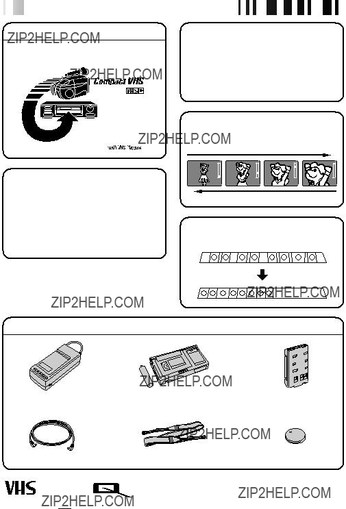
Random Assemble Editing (Z pg. 33 ??? 35)
PROVIDED ACCESSORIES
Cassettes marked 


 can be used with this camcorder.

EN 7 STARTEDGETTING
EDITING PLAYBACK
 RECORDING

8

 EN
EN


END indicator
Charge marker
** CHARGE MARKER
A charge marker is provided on the battery pack to help you remember whether it has been charged or not. Two colors are provided (red and


 GETTING
 STARTED
Power
This camcorder???s
NOTES:
cNo function is available without power supply.
cUse only specified power supply.
cDo not use provided power supply units with other equipment.
CHARGING THE BATTERY PACK
SUPPLY POWER
1 Connect the charger???s AC power cord to a wall outlet. The power indicator lights.
ATTACH BATTERY PACK
2 Align the marks and slide the battery pack in the direction of the arrow until it locks in place. The CHG. indicator lights.
DETACH BATTERY PACK
3 When charging is completed, the END indicator lights. Slide the battery pack opposite the direction of the arrow.
Hook on.
Push in.
BATT. RELEASE
ATTENTION:
Before detaching the power source, make sure that the camcorder???s power is turned off. Failure to do so can result in a camcorder malfunction.
USING THE BATTERY PACK
ATTACH BATTERY PACK
1 Hook its top end to the camcorder and push the battery pack in until it locks in place.
DETACH BATTERY PACK
2 Slide BATT. RELEASE and pull out the battery pack.
**REFRESH
The AC power adapter features a REFRESH function that allows you to fully discharge the battery pack before recharging.
To discharge the battery . . .
..... attach the battery pack to the adapter as shown in the illustration to the left. Then push REFRESH. The REFRESH indicator lights when discharging starts, and goes out when discharging is complete.
EN 9
NOTES:
cThe recording time per charge is affected by such factors as the time spent in Record/Standby mode and the frequency of zooming. It is safer to have spare battery packs.
cCharging times noted on page 8 are for fully discharged battey pack, and discharging times are for fully charged battery pack.
cCharging and discharging times vary according to the ambient temperature and the status of the battery pack.
cRemember to set the charge marker after charging a battery pack or after detaching a discharged one from your camcorder.
cPerform the REFRESH function after no less than 5 chargings.
cHigh temperatures can damage the battery pack, so use only where good ventilation is available. Don???t allow it to discharge in container, such as a bag.
cIf you stop recharging or discharging part way through, make sure to remove the battery pack before unplugging the adapter???s AC cord.
cRemove the battery pack from the adapter immediately after discharging.
cTo avoid interference with reception, do not use the AC Power Adapter/Charger near a radio.
cMake sure you unplug the DC cord before charging or discharging the battery pack.
cA blinking CHG. indicator means that the battery pack has become hot. Wait until it cools down to continue.
cThe CHG. indicator may not light properly with a brand new battery pack, or with one that???s been stored for an extended period. In this case, remove and reattach the battery pack and recharge it. The CHG. indicator should light during recharging. If not, contact your nearest JVC dealer.
To AC outlet
DC OUT
terminal
To DC in jack
Car Battery Charger/Adapter
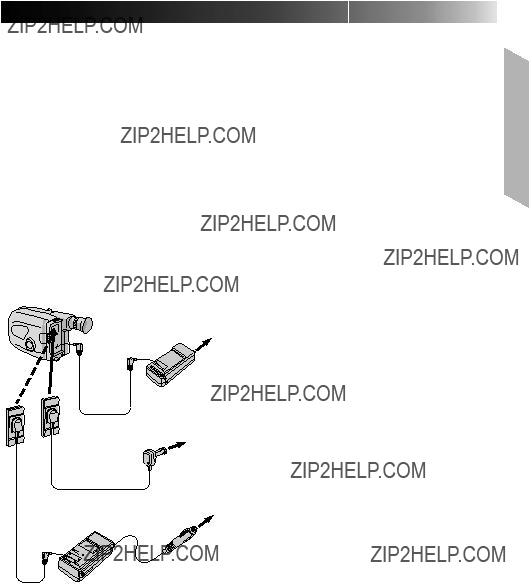
USING A CAR BATTERY
Use the optional Car Battery Cord or Car Battery Charger/Adapter (connect as shown in the illustration to the left).
NOTES:
cWhen using the car battery, leave the engine idling.
cThe optional Car Battery Charger
cWhen using the optional Car Battery Charger or Car Battery Cord
USING AC POWER
Use the AC Power Adapter (connect as shown in the illustration to the left).
NOTE:
The supplied AC Power Adapter/Charger features automatic voltage selection in the AC range from 110 V to 240 V.

10

 EN
EN 


 GETTING STARTED (cont.)
A
1
2
3 Insert a pointed,
4
5
INSERT BATTERY
Ensuring the plus (+) side is up, insert a CR2025 lithium battery and push it in.
CLOSE COVER
Close the compartment cover until it clicks in place.
NOTE:
See ???SAFETY PRECAUTIONS??? (Z pg. 2) for information on safe handling of lithium batteries.

 3
3
1 


 2
2
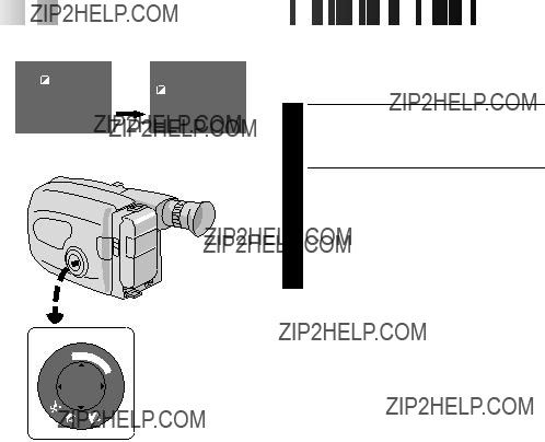
Set POWER to ???CAMERA???.
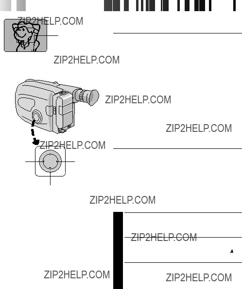
Viewfinder Adjustment
POSITION VIEWFINDER
1 Adjust the viewfinder manually for best viewability (see illustration at left).
SELECT MODE
2 Set the power switch to CAMERA.
ADJUST DIOPTER
3 Turn the diopter adjustment control until the indications in the viewfinder are clearly focused.
MENU
+
PROGRAM AE select dial
NEAR
END :MENU KEY
Set Time and
Date Screen
J A N 1 . 00 
 AM 12:00
SET
CANCEL
Date
Month/Day/Year
Time
???If you decide you want to return the date and time to the previous settings, press FAR or NEAR to move the highlight bar to ???CANCEL???, then press
MENU.
???If you???re satisfied with the settings, go on to step 5.
START CLOCK OPERATION
5 Once you???ve set the month, day, year and time, press FAR or NEAR until ???SET??? begins to blink, then press MENU. The Menu screen reappears.
CLOSE MENU
6 Press MENU.
NOTES:
cTo display the date and time in the viewfinder and on a connected TV, see ???Date/Time Insert??? (Z pg. 22).
cIf, in step 4, you input an invalid date (FEB 30, JUN 31, etc.) and perform step 5, ???INPUT ERROR??? appears blinking at the bottom of the screen. Press +,
12

 EN
EN 


 GETTING STARTED (cont.)
Set POWER to ???CAMERA???.
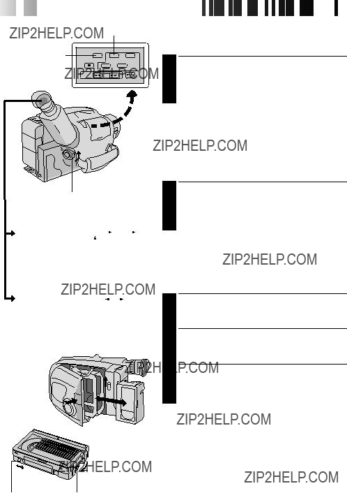
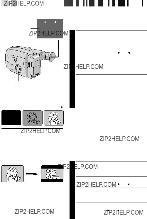
Tape length indicator
Tape Length Setting
Set the tape length according to the length of the tape used.
SET TAPE LENGTH
1 Press T20???30???40 until the required indication appears in the veiwfinder. T20 = 20 minutes of recording time, T30 = 30 minutes, and T40 = 40 minutes (in SP).
NOTE:
The tape remaining time (Z pg. 14) displayed in the viewfinder is correct only if the correct tape length has been selected.
Recording Mode Setting
Set depending on your preference.
SET RECORDING MODE
1 Press SP???EP button. ???SP??? (Standard Play) provides higher picture and sound quality and is better for dubbing, while ???EP??? (Extended Play) is more economical, recording at 1/3 the speed of SP.
NOTE:
If the recording mode is switched during recording, the playback picture will be blurred at the switching point.
Recording mode indicator
Turn to take up slack.
Loading/Unloading A Cassette
OPEN CASSETTE HOLDER
1 Slide EJECT until the holder opens. Do not use force to open.
INSERT/REMOVE CASSETTE
2 Make sure the label is facing outward.
CLOSE CASSETTE HOLDER
3 Press PUSH and make sure the holder is closed and locked.
NOTES:
cA cassette holder can???t be opened unless a power supply is attached.
cMake sure that the tape is not slack when loading the cassette. If there is any slack, turn the gear on the cassette in the direction of the arrow to take up the slack.
cMake sure the Erase Protection tab is in the position that allows recording. If not, slide the tab. Some cassettes have removable tabs. If the tab has been removed, cover the hole with adhesive tape.
cThe cassette holder can???t be opened while the camcorder is in the record mode.


 EN 13
EN 13
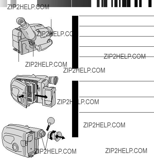
Grip Adjustment
EXPAND LOOP
1 Separate the Velcro strip.
Shoulder Strap Attachment
ATTACH STRAP
Following the illustration at left, thread the strap through the top of the eyelet 1, then fold it back and thread it through the keeper 2, and then through the buckle 3. Repeat the procedure to attach the other end of the strap to the other eyelet, making sure the strap isn???t twisted.
ADJUST LENGTH
2 Adjust as shown in the illustration at left 1, then slide both keepers snug against the eyelets to prevent slipping 2.
Tripod Mounting
ALIGN AND TIGHTEN
1 Align the screw and camera direction stud on the tripod with the camera???s mounting socket and stud hole. Then tighten the screw.

14

 EN
EN 


 RECORDING
 Basic Recording
Tape remaining time indicator

 LENS COVER switch
POWER
Start/Stop button
Tally lamp 
NOTE:
You should already have performed the procedures listed below. If not, do so before continuing.
cPower (Z pg. 8)
cTape Length setting (Z pg. 12)
cRecording Mode Setting (Z pg. 12)
cGrip Adjustment (Z pg. 13)
LOAD A CASSETTE
1 Slide EJECT to open the cassette holder, then insert the cassette with the label facing out. Press PUSH to ensure the holder is closed and locked.
ENTER
2 Slide the LENS COVER open/close switch to open the lens cover, then set the power switch to ???CAMERA???.
???The power indicator lights and the camcorder enters the
???The scene you???re aimed at appears on the viewfinder screen, with the word ???PAUSE??? superimposed upon it.
START SHOOTING
3 Press the RECORDING START/STOP button.
???The tally lamp lights while recording is in progress, and ???REC ??? appears in the viewfinder.
STOP RECORDING
4 Press the RECORDING START/STOP button again to stop recording.
???The camcorder
NOTES:
cA cassette holder can???t be opened unless a power supply is attached.
cThere may be a delay after you slide EJECT until the holder opens. Do not use force.
cThe tape???s remaining time is displayed in the viewfinder as shown.
cThe indicated remaining time is approximate.
cThe time required to calculate the remaining tape length, and the accuracy of the calculation, may vary according to the type of tape used.
cThe tape remaining time displayed in the viewfinder is correct only if the correct tape length has been selected (Z pg. 12).
c???TAPE END??? appears when the tape reaches its end, and the power goes off automatically if left in this condition for 5 minutes. ???TAPE END??? also appears when a cassette whose tape is already at its end is loaded.
cIf the
cIf the Recording Start/Stop button is pressed after the
cIf you???re recording on a cassette from the middle, use the RETAKE function (Z pg. 15) to find the end of the last recording so you don???t erase any of it.
cThe LENS COVER warning blinks for about 10 seconds when the camcorder is turned on, when the cover is closed.

RECORDING Basic Features
Power zoom switch
Zoom indicator
RETAKE (R/F)
16

 EN
EN 


 RECORDING Advanced
 Features
1 second later, the mode is activated.
SEPIA
After 1 sec.
Viewfinder
Program AE With Special Effects
All you have to do to access any of the variety of shooting effects is to turn the PROGRAM AE select dial.
SELECT MODE
1 Turn the PROGRAM AE select dial until the symbol of the function you want is aligned with the mark.
???The selected mode???s name and its indication are displayed in the viewfinder for approx. 1 second. Then the name disappears, and only the indication remains. The mode is activated.
???When Auto Mode Lock or Auto Mode Release mode is selected, only the mode???s name is displayed. Then the name disappears and the mode is activated.
NOTES:
cOnly one effect can be engaged at a time.
cThe screen becomes slightly reddish when the fader (Z pg. 20) is used in the Sepia mode.
cThe screen becomes slightly dark in the High Speed Shutter mode. Use in
cIn the High Speed Shutter or Sports modes, picture color may be adversely affected if subject is lit by alternating
Auto Mode Lock
Locks the camcorder in Full Auto mode, preventing incorrect operation due to accidental button pressing during shooting.
???In this mode the following controls are disabled; FADE, WIDE, TITLE, DISPLAY, M.W.B (Manual White Balance), Manual Focus, Focus Lock, Exposure Control and MENU
Auto Mode Release
Electronic Fog Filter
Makes the picture look misty white, as when an external fog filter is attached to the lens. Softens the image and gives it a ???fancy??? look.
ND Effect
A black mist darkens the picture, as when an ND filter is used. Helps to counter the effects of glare on the subject.

SEPIA Sepia
Sepia
The scene being shot is recorded in
 TWILIGHT Twilight
Twilight
Dusk, twilight scenery, fireworks, etc., look more natural and dramatic. The following happens when Twilight mode is selected:
???Auto gain control is turned off.
???White Balance is set to ???

 ??? (outdoor mode), but
can also be manually changed to another mode (Z pg. 23).
???Auto Focus becomes available only in the range of 10 m to infinity. To focus when the
camera distance is less than 10 m, use manual focusing (Z pg. 19).
+
+02
???Exposure Level Indicator
To brighten the image
To darken the image


 EN 17
EN 17
 SPORTS Sports
Sports
High shutter speed clearly captures
Captures faster action than Sports mode.
Exposure Control
This feature automatically adjusts the iris for the best available picture quality, but you can override and make the adjustment manually.
SELECT MODE
1 Turn the PROGRAM AE select dial to any position except AUTO LOCK.
BRIGHTEN IMAGE
2 Press + (maximum +06). The Exposure level indicator appears in the viewfinder.
OR . . .
DARKEN IMAGE
Press ??? (maximum
When you want to return to the factory setting . . .
RESTORE INITIAL SETTING
3 Press + and ??? simultaneously. The standard setting is immediately restored and the Exposure level indicator disappears.
18

 EN
EN 


 RECORDING
 Advanced
 Features
 (cont.)
Focusing
Focus
detection zone
PROGRAM AE select dial
Auto Focus
The camcorder???s Full Range AF system offers continuous shooting ability from
???When two subjects overlap in the same scene. ???When illumination is low.*
???When the subject has no contrast (difference in brightness and darkness), such as a flat,
???When a dark object is barely visible in the viewfinder.* ???When the scene contains minute patterns or identical
patterns that are regularly repeated.
???When the scene is affected by sunbeams or light reflecting off the surface of a body of water.
???When shooting a scene with a
*The 

 ??? appears in the viewfinder.
Focus Lock
This feature locks the focus in place, which is especially helpful in the following situations:
???When things pass between your subject and the camcorder. Engage the focus lock function to lock your subject in before recording.
???When you want your subject to be focused, and to appear in a corner of the screen. First, center on the subject and focus using auto focus mode. Then engage the focus lock function and move the camcorder until the subject is where you want it.
SELECT MODE
1 Turn the PROGRAM AE select dial to any position except AUTO LOCK.
LOCK FOCUS
2 Press FAR or NEAR. The focus lock indication ???  ??? appears in the viewfinder.
RELEASE FOCUS LOCK
3 Press FAR and NEAR simultaneously. The focus lock indication disappears.
NOTES:
cIf the lens is smeared or blurred, accurate focusing is not possible. Keep the lens clean, wiping with a piece of soft cloth if it gets dirty. When condensation occurs, wipe with a soft cloth or wait for it to dry naturally.
cWhen shooting a subject close to the lens,
depending on the distance between the camcorder and the subject. *When Tele Macro (Z pg. 25) is activated, the camcorder will not zoom out automati- cally.

Power zoom lever
PROGRAM AE select dial
20

 EN
EN 


 RECORDING
 Advanced
 Features
 (cont.)
Function indication
FADE
SELECT button
PROGRAM AE select dial
SET button
FADE IN
Fader
This feature allows smooth
SELECT MODE
1 Turn the PROGRAM AE select dial to any position except AUTO LOCK.
SELECT FUNCTION
2 Press SELECT repeatedly until ??? FADE ??? appears.
ENGAGE
3 Press SET to engage the
START RECORDING
4 Press Recording Start/Stop to start recording and activate
OR . . .
END RECORDING
Press Recording Start/Stop to end recording and engage
NOTES:
c Pressing and holding the Recording Start/Stop button allows you to record a black blank screen.
Wide
This feature allows you to record black bars at the top and bottom of the screen to produce a
3 Press SET.
RESTORE NORMAL SCREEN
4 Press SET again while ??? WIDE ??? appears.
Title indication
TITLE
 HAPPY BIRTHDAY
OUR VACATION
MERRY CHRISTMAS
A SPECIAL DAY
No indication HAPPY HOLIDAYS


 EN 21
EN 21
Instant Titles
The camcorder has eight preset titles in memory. You can superimpose one of them above a previously stored title as shown in the illustration to the left.
DISPLAY
SELECT MODE
Turn the PROGRAM AE select dial to any position except
AUTO LOCK.
SELECT
OUR NEW BABY
WEDDING DAY
SELECT FUNCTION
TITLE ??? appears.
SET
CONGRATULATIONS
The characters you MENU have set using
Character Generator
PROGRAM AE select dial
cTo erase a character you entered mistakenly, make ???CLEAR??? blink by pressing +,  ??? in the top left corner. Press MENU.
cTo display the characters you have set ??? ???Instant Title??? or ???Date/Time/Character Insert??? (Z pg. 22).
cCharacters may be set only in the

SET
Auto Date Record mode  Date display
Character Generator  Date/Time display
Auto Date Record mode
Character Generator
This feature allows you to display date, time and characters in your viewfinder and on a connected color monitor, record them manually or automatically, and even make your own titles.
NOTE:
You should already have performed the Date/Time Setting procedure (Z pg. 11). If you haven???t, do so before continuing.
DISPLAY
SELECT MODE
1 Turn the PROGRAM AE select dial to any position except AUTO LOCK.
SELECT DISPLAY
2 Press SELECT repeatedly until ??? DISP. ??? appears.
CHOOSE DISPLAY MODE
3 Press SET while in
NOTES:
cThe selected display can be recorded.
cIf you don???t want to record the display, select
cIf you want to delete the display during shooting, press
SET.
cIf you want to call back a deleted display, engage the
AUTO DATE RECORD
Your camcorder automatically records the date for about 5 seconds after recording is initiated in the following situations:
???After changing the date. ???After loading a cassette.
???After Auto Date Record mode is selected by pressing
SE T.
In this mode, the date is replaced after 5 seconds with ???AUTO DATE???.
NOTES:
cSetting PROGRAM AE to LOCK always engages the auto date record mode, and disables all other modes.
cIn the Auto Date Record mode, if the date changes while you???re shooting, the date indication is recorded for about 5 seconds from that point. It is not recorded during any other recordings made on that day.

White balance mode indicator
MWB
SELECT
SET
PROGRAM AE select dial


 EN 23
EN 23
Manual White Balance Adjustment (M.W.B.)
This camcorder???s Automatic Color Temperature system senses the color temperature of the ambient lighting for automatic white balance adjustment. However, precise color adjustment is not possible under the following conditions:
???When an object is in various shades of the same color.
???When a predominantly red or brown object is being shot outdoors.
In these cases, use the camcorder???s
SELECT MODE
1 Turn the PROGRAM AE select dial to any position except AUTO LOCK.
SELECT FUNCTION
2 Press SELECT reapeatedly until ??? M.W.B. ??? appears.
SELECT WHITE BALANCE
3 Press SET (Manual White Balance) until the required indication appears in the viewfinder.
???MWB??? ..... With a memorized personal White Balance setting (see below)
???

 ??? ......... Outdoors on sunny day
???
 ???......... Outdoors on cloudy day
???

 ??? .......... Light source is halogen or tungsten lamp
MWB
MWB sets the color temperature for the subject???s light source so you can shoot with natural colors that are unaffected by surroundings, even when there are multiple subjects with different color temperatures.
1
2
SELECT MODE
Turn the PROGRAM AE select dial to any position except AUTO LOCK.
ADJUST FOCUS
Point the camcorder at a white, flat object such as a sheet of white paper, and adjust focus manually (Z pg. 19).
ADJUST WHITE BALANCE
3 Press SET until ???MWB??? appears, then press and hold SET for more than 3 seconds.
??? ???MWB??? blinks in the viewfinder during adjustment, then stops blinking but stays lit when adjustment is complete.
NOTES:
cTo switch to automatic white balance adjustment, press SET until the indication disappears, or turn the PROGRAM AE select dial to ???AUTO LOCK???.
c
cIt is helpful to connect your camcorder to a color monitor when adjusting the white balance (???Basic Connections??? Z pg. 29).
cWhen adjusted by putting colored paper in front of the subject in step 2 (???ADJUST FOCUS???), this unit makes its color temperature standard for automatic white balance. So you can enjoy shooting with different colors. For example, when adjusting with red, blue or yellow colors, the image becomes the color which aproximates to green, orange or purple respectively.

+
SET CHARACTER
DATE/TIME
END :MENU KEY
 PAUSE
PAUSE
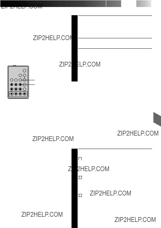
This camcorder is equipped with Program Manager, an
SELECT MODE
1 Turn the PROGRAM AE select dial to any position except AUTO LOCK.
ACCESS MENU SCREEN
2 Press MENU.
SELECT FUNCTION
3 Press + or ??? to place the highlight bar on the desired function.
MAKE SETTING
4 The setting procedure depends on the function you select.
If you select GAIN UP, TELE MACRO, INTERVAL TIMER, REC TIME or JLIP ID NO. . . .
.... press FAR or NEAR to cycle through the choices until the desired setting appears.
If you select SET CHARACTER or DATE/TIME, . . .
.... press NEAR to access the selection menu for each function (SET CHARACTER ??? Z pg. 21; DATE/TIME ??? Z pg. 11).
CLOSE MENU
5 Press MENU. The normal screen reappears.
NOTE:
The menu is available only in the
If GAIN UP or TELE MACRO in the Menu has been changed from the factory settings, this mark appears in the viewfinder.


 = Factory setting and when the PROGRAM AE Select Dial is set to
AUTO LOCK
NOTE:
During shooting in low light, Auto Focus accuracy may decrease even when Gain Up is used. In this case, use Manual Focus (Z pg. 19).

26

 EN
EN 


 RECORDING
 Advanced
 Features
 (cont.)
+
FAR ???
3
START DELAYED RECORDING
5MIN
 1MIN
1MIN
 30S
30S
 15S
15S
 OFF
OFF

Animation
Give stationary scenes or objects an illusion of movement. This function allows you to shoot a series of pictures, each slightly different, of the same object for a brief period of time.
NOTE:
Make sure the camcorder is in the
ACCESS MENU SCREEN
1 Turn the PROGRAM AE select dial to any position except AUTO LOCK, then press
MENU.
SET RECORDING TIME
2 Press ??? or + to move the highlight bar down to ???REC TIME???, then press FAR or NEAR to cycle through the choices. Stop when the desired time appears. Choose from ???1/4S???, ???1/2S???, ???1S???, or select to turn the function ???OFF???. Then press MENU to close Menu screen.
START RECORDING
3 Press the Recording Start/Stop button after focusing on the subject. The recording stops automatically after the selected period of time.
ASSEMBLE SERIES OF
PICTURES
4 Repeat step 3 for the desired number of pictures.
RELEASE ANIMATION MODE
5 Set ???REC TIME??? in the Menu screen to ???OFF???.
NOTES:
cFor best results, make sure the camcorder is secured when shooting in Animation or
c
cBefore performing other operations following Animation or


 EN 27
EN 27
You can record sequentially at preset time spans. Leaving the camcorder aimed at a specific subject, you can record subtle changes over an extended period of time.
NOTE:
Make sure the camcorder is in the
ACCESS MENU SCREEN
1 Turn the PROGRAM AE select dial to any position except AUTO LOCK, then press
MENU.
SET INTERVAL BETWEEN
RECORDINGS
2 Press ??? or + to move the highlight bar down to ???INTERVAL TIMER???, then press FAR or NEAR to cycle through the choices. Stop when the desired time appears. Choose from ???15S???, ???30S???, ???1MIN???, ???5MIN???, or select to turn the function ???OFF???.
SET RECORDING TIME
3 Press ??? or + to move the highlight bar down to ???REC TIME???, then press FAR or NEAR to cycle through the choices. Stop when the desired time appears. Choose from ???1/4S???, ???1/2S???, ???1S???, or select to turn the function ???OFF???. Then press MENU to close Menu screen.
START
RECORDING
4 Press the Recording Start/Stop button. Recording and intervals alternate automatically.
RELEASE
5 To release when the tally lamp is not blinking, set ???REC TIME??? and ???INTERVAL TIMER??? in the Menu screen to ???OFF???. To release when the tally lamp is blinking, press the Recording Start/Stop button to stop the blinking, then set ???INTERVAL TIMER??? and ???REC TIME??? in the Menu screen to ???OFF???.

28

 EN
EN 


 PLAYBACK
 Using
Using The
The Cassette
 Adapter
Cassette Adapter (VHS PlayPak)
Use this to play back a
+ 
VCR
Compartment door
Sliding latch
Compact video cassette
Reels
Recording safety hole
INSERT BATTERY
1 Slide the battery cover up to remove it, and install one ???AA(R6)??? size battery as shown in the illustration at left. Then reattach the cover.
INSERT CASSETTE IN ADAPTER
2 Slide the latch to open the adapter compartment door, then insert the cassette and close the compartment door.
PLAY BACK ON CONNECTED VCR
3 Load the cassette adapter into the VCR and play the tape back as you would any other.
REMOVE CASSETTE FROM
ADAPTER
4 Slide the latch and the compartment door opens automatically. Then insert your finger in the hole on the underside of the adapter as shown in the illustration at left, push up and remove the cassette.
NOTES:
cDuring tape loading and unloading, do not touch the reels for safety and tape protection.
cDuring
cTo record on a VCR using a compact cassette and the adapter, cover the adapter???s recording safety hole with adhesive tape.

PLAYBACK Basic Connections


 EN 29
EN 29
There are three basic types of connections. When making the connections, refer also to your VCR and TV instruction manuals.
Connection To A VCR [A]
(Editing, Dubbing and Playback)
NOTE:
When 
 connecting the cables, open
  the jack cover.
To AUDIO and VIDEO connectors
Audio and Video cables (optional)
Use the optional Audio and Video cables.
CONNECT CAMCORDER TO VCR
1 As shown in the illustration at left, connect the optional Audio and Video cables between the AUDIO and VIDEO connectors on the camcorder and those on the VCR.
A
To AUDIO and
VIDEO IN connectors
B
SUPPLY POWER
2 Turn on the camcorder, the VCR and the TV.
SELECT MODE
VCR
Antenna
RF unit
NOTES:
cIt is recommended to use the AC Power Adapter/Charger as the power supply instead of the battery pack.
cTo monitor the picture and sound from the camcorder without inserting a tape, set the camcorder???s Power switch to ???CAMERA???, then set your TV to the appropriate input mode.
cIf you have a TV or speakers that are not specially shielded, do not place the speakers adjacent to the TV as interference will occur in the camcorder playback picture.
3 Set the VCR to its AUX input mode, and set the TV to its VIDEO mode.
Connection To A TV With A/V Input Connectors [B] (Playback ONLY)
NOTE:
Use the optional Audio and Video cables.
CONNECT CAMCORDER TO TV
1 As shown in the illustration at left, connect the optional Audio and Video cables between the AUDIO and VIDEO connectors on the camcorder and those on the TV.
SELECT MODE
2 Set the TV to its VIDEO or AV mode (as specified in its instructions).
Connection To A TV With NO A/V Input Connectors (Playback ONLY)
NOTE:
Use the optional
*Refer to the

30

 EN
EN 


PLAY/PAUSE
REW FF
STOP
POWER
Recording mode indicator


 PLAYBACK
 Basic
Basic Playback
NOTE:
Make sure you connect your camcorder as directed in ???Basic Connections??? (Z pg. 29).
LOAD A CASSETTE
1 Slide EJECT to open the cassette holder, then insert the cassette with the label facing out. Press PUSH to ensure the holder is closed and locked.
SELECT MODE
2 Set the Power switch to ???PLAY???. The Power On indicator lights.
PLAYBACK
3 Press PLAY/PAUSE. The playback picture appears in the viewfinder and the connected TV.
STOP PLAYBACK
4 Press STOP.
Rewind or
Press REW to rewind, or FF to
NOTE:
The camcorder shuts off automatically after about 5 minutes in Stop mode or Still Playback mode. To turn on again, set the Power switch to ???POWER OFF???, then to ???PLAY???.
PLAYBACK Features
+
???
COUNTER R/M PLAY/PAUSE
STOP
REW FF
NOTES: c The counter memory functions in the FF and REW modes.
cTo disable Counter Memory Function, press COUNTER R/M so the ???M??? disappears.

32

 EN
EN 


Power switch
When connecting  the cables, open the
  jack cover.
Audio and Video cable (optional)
To AUDIO and
VIDEO OUT connectors
To AUDIO and
VIDEO IN connectors
VCR (Recording deck)
Random Assemble Editing [R.A.Edit]
Create edited videos easily using your camcorder as the source player. You can select up to 8 ???cuts??? for automatic editing, in any order you like. R.A.Edit is more easily performed when the optional
VCR CODE LIST
 EN 33
EN 33
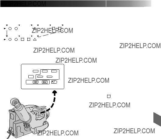
SET REMOTE/VCR CODE
SET REMOTE TO OPERATE VCR
1 Turn off the power to the VCR and point the remote toward the VCR???s infrared sensor. Then, referring to the VCR CODE LIST on the left, press and hold MBR SET, and press button (A) and then (B).
???The code is automatically set once you release the MBR SET button, and the VCR???s power comes on.
OPERATE THE VCR
2 Make sure the VCR???s power is on. Then, while holding VCR CTL, press the button on the remote for the desired function. The functions the remote can control are PLAY, STOP, PAUSE, FF, REW and VCR REC STBY (you don???t need to press VCR CTL for this one).
You???re now ready to try Random Assemble Editing.
IMPORTANT
Although the MBR is compatible with JVC VCRs and those of many other makers, it may not work with yours or may offer limited functions.
NOTES:
cIf the VCR???s power doesn???t come on in step 1, try another code from the VCR CODE LIST.
cSome brands of VCR don???t come on automatically. In this case, turn the power on manually and try step 2.
cIf the
cThe
MAKE CONNECTIONS
CONNECT TO . . .
1 A JVC VCR EQUIPPED WITH REMOTE
PAUSE TERMINAL
Connect the editing cable to the Remote PAUSE terminal.
B JVC VCR NOT EQUIPPED WITH REMOTE
PAUSE TERMINAL
Connect the editing cable to the R.A.EDIT connector.
C
Connect the editing cable to the
All other connections are as shown in the illustration on page 34.
CONTINUED ON NEXT PAGE

34

 EN
EN 


 EDITING (cont.)
REW/FF
PREPARE CAMCORDER
Insert a recorded tape and set the Power switch to ???PLAY???.
PREPARE VCR
Turn the power on, insert a recordable tape and engage the AUX mode (refer to VCR???s instructions).
To AUDIO  and VIDEO
  out connectors
Audio and Video cable (optional)
To AUDIO and VIDEO IN connectors
Open the cover
To J terminal  (JLIP)
Editing cable (optional, 3.5??
SELECT SCENES
ACCESS R.A. EDIT COUNTER
 DISPLAY
1 Press PLAY/PAUSE, then press R.A. EDIT and the counter display appears in the viewfinder and the screen of the connected TV.
REGISTER BEGINNING OF SCENE
2 Press REW or FF to locate the beginning of a scene you want, then press IN/OUT to register that point. The data appears under IN on the display.
REGISTER END OF SCENE
3 Press REW or FF to locate the end of the scene and press IN/OUT to register it. The data appears under OUT on the display. The total time of the registered scene(s) is displayed at the bottom of the screen.
REGISTER ADDITIONAL SCENES
4 Repeat steps 2 and 3 for each additional scene (as many as 8).
MAKE CORRECTIONS
VCR (Recording deck)
5 Press CANCEL during steps 2 and 3 to erase the most recently registered point.
NOTES:
cThere must be at least one second between an
cTo ensure correct operation, leave at least 15 seconds open between scenes.
cBlank portions of tape cannot be registered as
cIf it takes more than 5 minutes to search for an
cPressing R.A.EDIT clears all in- and
cLeave a small margin for error around each
NOTES:
cIf you performed step 1 C on page 33 (???MAKE CONNECTIONS???), keep the remote control pointed at the VCR during editing.
c The
c There may be noise at in- or
36

 EN
EN 


LENS COVER open/close switch
Set to ???POWER OFF???.
BATT. RELEASE
EJECT
PUSH
Remove
Marks


 USER
USER MAINTENANCE
After Use
1 Set the Power switch to ???POWER OFF??? to turn off the camcorder.
2 Slide EJECT to open the cassette holder, then remove the cassette.
3 Close and lock the cassette holder by pressing
PUSH.
4 Press BATT. RELEASE to remove the battery pack.
5 Slide the LENS COVER open/close switch to close the lens cover.
Cleaning The Camcorder
CLEAN EXTERIOR
1 Wipe gently with a soft cloth.
CLEAN LENS
2 Blow it with a blower brush, then wipe gently with lens cleaning paper.
CLEAN VIEWFINDER
3 1 Turn the eyepiece counterclockwise and pull it out.
2 Remove dust using a blower brush.
3 Align the marks,
NOTES:
cAvoid using strong cleaning agents such as benzine or alcohol.
cCleaning should be done only after the battery pack has been removed or other power units have been disconnected.
cMold may form if the lens is left dirty.

The power suddenly goes off and doesn???t come back on by itself.
cThe battery pack has completely discharged.
cRemove the cassette and disconnect the power source, then after a few minutes, try turning the power back on. If it still doesn???t come on, consult your nearest JVC dealer.
RECORDING
PLAYBACK
The tape is running, but there???s no playback picture.
cThe TV has not been set to its VIDEO mode or channel.
cIf A/V connection is used, the TV???s VIDEO/TV switch has not been set to VIDEO.
cThe RF unit has not been set to the correct channel.
Noise bars appear in the playback picture.
c Manual Tracking has not been performed (Z pg. 31).

The image is out of focus.
cThe diopter needs to be adjusted (Z pg. 10).
cThe scene being shot is adversely affecting the operation of Auto Focus (Z pg. 18).
A character generator title and the date and time displays disappear from the viewfinder.
cIf you remove the power source from the camcorder while the power is on, all settings and selections are erased. Make sure to turn the camcorder???s power off before disconnecting the power source.
Even though the Lens Cover is open, the Lens Cover Warning indicator blinks.
cThe Lens Cover Warning indicator may blink when the camcorder is used in dark areas, regardless of the position of the Lens Cover.
The camcorder is a

INDEX Viewfinder 


 EN 39
EN 39
Viewfinder Indications
When no cassette is inserted or when Erase Protection tab is not in the position that allows recording, the Cassette ( )Warning blinks.
%Battery Pack Remaining Power Indicator Changes as follows according to the battery pack???s
remaining power level: ???


 ???. When the power is almost gone, the indicator blinks, then the unit shuts off. Replace the battery pack with a fully charged one.
(Note: The symbol containing 3 darkened
squares ???  ??? does not necessarily mean that the battery pack is fully charged.)
) Clock Warning
Displayed for about 5 seconds if the clock (lithium) battery is not in place or is exhausted when power is turned on. Also displayed for about 5 seconds when clock battery becomes
q Condensation Warning
When this indication appears, all functions are disabled. Turn the unit off (without removing the power source) for a few hours, and when you turn it on again the indicator should disappear.
w Tape End Display ................................ Z pg. 14 Appears when the end of the tape is reached during playback, recording or


 EN 41
EN 41
Q W E R T
o
u
w p
U
e r t y i Y
Connectors
wJ terminal (JLIP (Joint Level Interface Protocol) Connector.)
(Located beneath the jack cover)
???Connect the Editing Cable when performing Random Assemble Editing (Z pg. 34).
???It is used to connect the camcorder to a device such as a personal computer.
For further detail consult your nearest JVC dealer. Information (in English) is also available at our home page:
Other Parts
o Camera sensor
Be careful not to cover this area;
Indicators

42

 EN
EN 


 INDEX
INDEX Terms
Terms
A
N
B
Q

CAUTIONS


 EN 43
EN 43
When using the AC Power Adapter/Charger in areas other than the USA
nThe provided AC Power Adapter/Charger features automatic voltage selection in the AC range from 110 V to 240 V.
USING HOUSEHOLD AC PLUG ADAPTER
In case of connecting the unit???s power cord to an AC wall outlet other than American National Standard C73 series type use an AC plug adapter, called a ???Siemens Plug???, as shown.
For this AC plug adapter, consult your nearest JVC dealer.
Plug adapter
INFORMATION
This device complies with Part 15 of FCC Rules. Operation is subject to the following two condi- tions:
(1) This device may not cause harmful interference, and (2) this device must accept any interference received, including interference that may cause undesired operation. Change or modifications not approved by the party responsible for compliance could void the user???s authority to operate the equipment. This equipment has been tested and found to comply with the limits for a Class B digital device, pursuant to Part 15 of the FCC Rules. These limits are designed to provide reasonable protection against harmful interference in a residential installation. This equipment generates, uses, and can radiate radio frequency energy and, if not installed and used in accordance with the instruc- tions, may cause harmful interference to radio communications. However, there is no guarantee that interference will not occur in a particular installation. If this equipment does cause harmful interference to radio or television reception, which can be determined by turning the equipment off and on, the user is encouraged to try to correct the interference by one or more of the following measures:
Reorient or relocate the receiving antenna. Increase the separation between the equipment and receiver.
Connect the equipment into an outlet on a circuit different from that to which the receiver is connected.
Consult the dealer or an experienced radio/TV technician for help.
General Battery Precautions
???When the
???Use only the following batteries:
Please make note of the following rules for battery use. When misused, batteries can leak or explode.
1.Refer to the
2.Do not expose batteries to excessive heat as they can leak or explode.
3.Do not dispose of batteries in a fire.
4.Remove the battery from the unit if it is to be stored for an extended period to avoid battery leakage which can cause malfunctions.
2.To prevent damage and prolong service life . . .
.... do not subject to unnecessary shock.
.... avoid repeated charging without fully discharging.
.... charge in an environment where temperatures are within the tolerances shown in the chart below. This is a chemical reaction type
.... store in a cool, dry place. Extended exposure to high temperatures will increase natural discharge and shorten service life.
.... avoid prolonged uncharged storage.
.... remove from charger or powered unit when not in use, as some machines use current even when switched off.

44

 EN
EN 


 CAUTIONS (cont.)
3. To prevent damage to the camcorder . . .
.... replace the battery pack when it begins to deliver less recording time per charge.
NOTE:
It is normal for the battery pack to be warm after charging, or after use.
Temperature Range Specifications
NOTES:
cRecharging time is based on room temperature of 20??C.
cThe lower the temperature, the longer recharging takes.
Cassettes
To properly use and store your cassettes, be sure to read the following cautions:
2.Avoid using the unit . . .
.... in places subject to excessive humidity or dust.
.... in places subject to soot or steam such as near a cooking stove.
.... in places subject to excessive shock or vibration.
.... near a television set.
.... near appliances generating strong magnetic or electric fields (speakers, broadcasting antennas, etc.).
.... in places subject to extremely high (over 40??C or 104??F) or extremely low (under 0??C or 32??F) temperatures.
3.DO NOT leave the unit . . .
.... in places of over 50??C (122??F).
.... in places where humidity is extremely low (below 35%) or extremely high (above 80%).
.... in direct sunlight.
.... in a closed car in summer.
.... near a heater.
1.During use . . .
.... make sure the cassette bears the
.... be aware that recording onto prerecorded tapes automatically erases the previously recorded video and audio signals.
.... make sure the cassette is positioned properly when inserting.
.... do not load and unload the cassette repeatedly without allowing the tape to run at all. This slackens the tape and can result in damage.
.... do not open the front tape cover. This exposes the tape to fingerprints and dust.
2.Store cassettes . . .
.... away from heaters or other heat sources.
.... out of direct sunlight.
.... where they won???t be subject to unnecessary shock or vibration.
.... where they won???t be exposed to strong magnetic fields (such as those generated by motors, transformers or magnets).
.... vertically, in their original cases.
Main Unit
1.For safety, DO NOT . . .
.... open the camcorder???s chassis.
.... disassemble or modify the unit.
....
.... allow inflammables, water or metallic objects to enter the unit.
.... remove the battery pack or disconnect the power supply while the power is on.
.... leave the battery pack attached when the camcorder is not in use.
4.To protect the unit, DO NOT . . .
.... allow it to become wet.
.... drop the unit or strike it against hard objects.
.... subject it to shock or excessive vibration during transportation.
.... keep the lens directed at extremely bright objects for long periods.
.... direct the eyepiece of the viewfinder at the sun.
.... carry it by holding the viewfinder.
.... swing it excessively when using the shoulder strap.
5.This camcorder features a
About moisture condensation . . .
???You have observed that pouring a cold liquid into a glass will cause drops of water to form on the glass??? outer surface. This same phenomenon occurs on the head drum of a camcorder when it is moved from a cool place to a warm place, after heating a cold room, under extremely humid conditions or in a place directly subjected to the cool air from an air conditioner.
???Moisture on the head drum can cause severe damage to the video tape, and can lead to internal damage to the camcorder itself.
Serious malfunctioning
If malfunctioning occurs, stop using the unit immediately and consult your local JVC dealer.

SPECIFICATIONS 


GENERAL
CAMERA
VIDEO


 EN 45
EN 45
AC POWER ADAPTER/BATTERY CHARGER
CASSETTE ADAPTER
Provided Accessories ......................Z pg. 6
Optional Accessories
???Battery Packs
???Car Battery Charger
???Battery Charger
???Car Battery Cord
???RF Unit
???Compact
???Active Carrying Bag
???Wireless Remote Control Unit
The
This comcorder can use the
Some acccessories are not available in some areas. Please consult your nearest JVC dealer for details on accessories and their availability.
Specifications shown are for SP mode unless otherwise indicated. E. & O. E. Design and specifications subject to change without notice.


EN
VICTOR COMPANY OF JAPAN, LIMITED