Owner's Operator And Maintenance Manual
Ranger II??? Storm Series??
Wheelchairs
MWD/FWD
Ranger IIBASIC
Ranger IISTANDARD
Ranger IIJR
Ranger II250 SERIES
DEALER:THIS MANUAL MUST BE GIVENTOTHE USER OF
THEWHEELCHAIR.
USER: BEFORE USINGTHISWHEELCHAIR, READTHIS
MANUALAND SAVE FOR FUTURE REFERENCE.
WARNING
DO NOT OPERATE THIS EQUIPMENT WITHOUT FIRST READING AND
UNDERSTANDING THIS MANUAL. IF YOU ARE UNABLE TO
UNDERSTAND THE WARNINGS, CAUTIONS, AND INSTRUCTIONS,
CONTACT A HEALTHCARE PROFESSIONAL, DEALER OR TECHNICAL
PERSONNEL IF APPLICABLE BEFORE ATTEMPTING TO USE THIS
EQUIPMENT - OTHERWISE INJURY OR DAMAGE MAY RESULT.
THE INITIAL SET UP OF THIS WHEELCHAIR MUST BE PERFORMED BY A
QUALIFIED TECHNICIAN.
PROCEDURES OTHER THAN THOSE DESCRIBED IN THIS MANUAL
MUST BE PERFORMED BY A QUALIFIED TECHNICIAN.
SPECIAL NOTES
WARNING/CAUTION notices as used in this manual apply to hazards or unsafe practices which could result in personal injury or property damage.
NOTICE
THE INFORMATION CONTAINED IN THIS DOCUMENT IS SUBJECT TO CHANGE WITHOUT NOTICE.
WHEELCHAIR USER
As a manufacturer of wheelchairs, Invacare endeavors to supply a wide variety of wheelchairs to meet many needs of the user. However, final selection of the type of wheelchair to be used by an individual rests solely with the user and his/her healthcare professional capable of making such a selection.
WHEELCHAIR TIE-DOWN RESTRAINTS AND SEAT POSITIONING STRAPS
Invacare recommends that wheelchair users NOT be transported in vehicles of any kind while in wheelchairs. As of this date, the Department of Transportation has not approved any tie-down systems for transportation of a user while in a wheelchair, in a moving vehicle of any type.
It is Invacare???s position that users of wheelchairs should be transferred into appropriate seating in vehicles for transportation and use be made of the restraints made available by the auto indus- try. Invacare cannot and does not recommend any wheelchair transportation systems.
AS REGARDS RESTRAINTS - SEAT POSITIONING STRAPS - IT IS THE OBLIGATION OF THE DME DEALER,
THERAPISTS AND OTHER HEALTHCARE PROFESSIONALS TO DETERMINE IF A SEAT POSITIONING STRAP
IS REQUIRED TO ENSURE THE SAFE OPERATION OF THIS EQUIPMENT BY THE USER. SERIOUS INJURY
CAN OCCUR IN THE EVENT OF A FALL FROM A WHEELCHAIR.
SAVE THESE INSTRUCTIONS
SPECIFICATIONS
SPECIFICATIONS
Overall Length (Drive wheel in Front Position - Refer to PERCENTAGE OF WEIGHT DISTRIBUTION in
PROCEDURE 1 of this manual.)
Front Stabilizers
Drive Wheels/Tires:
Casters w/Precision Sealed Bearings:
Footrest/Legrest:
Battery/Size (Not Supplied):
7-inch Urethane
12-1/2 x 2-1/4-in. (Std.); 14-in.x 3-in. (Opt.) (Flat Free or Pneumatic)
8 x 1-3/4-in. Semi Pneumatic (Std.), 8 x 2-in. Pneumatic (Opt.) 6 x 2-in. Semi Pneumatic (Opt.)
Swingaway, Removable Footboard
RANGER IIBASIC/RANGER IISTANDARD - 22NF Gel Cell (Two (2) Required); RANGER II250 SERIES uses- U1 GEL CELL)
v NOTE: Refer to PERCENTAGE OF WEIGHT DISTRIBUTION in PROCEDURE 1 of this manual.
Footnotes:
1.High Back not available on model RANGER II250 SERIES.
2.Low and High Back Types have an Infinite adjust- ment. Low Backs with Solid Seat have no adjustment.
3.18-in. wide x 16-in. deep wheelchair with MKIV RII electronics.
4.Range will vary with battery conditions, surface, ter- rain and operators weight.
5.Includes seating systems and accessories.
6.Weight varies between motors. RANGER IIBASIC AND RANGER II250 SERIES have clutches. The RANGER IISTANDARD has motor locks.
INTEGRATED SLING SEAT AND CAPTAIN'SSEAT
S
P
E
C
I
F
I
C
A
T
I
O
N
S
Overall Length
With 8-in. rear casters and 93 front riggings:
With 8-in. rear casters and no front riggings:
Drive Wheels/Tires:
Casters w/Precision Sealed Bearings:
Footrest/Legrest:
Battery/Size (Not Supplied):
vNOTE: Refer to PERCENTAGE OF WEIGHT DISTRIBUTION in PROCEDURE 1 of this manual.
12-1/2 x 2-1/4-in. (Std.); 14-in.x 3-in. (Opt.) (Flat Free or Pneumatic)
8 x 1-3/4-in. Semi Pneumatic (Std.), 8 x 2-in. Pneumatic (Opt.) 6 x 2-in. Semi Pneumatic (Opt.)
Swingaway, Removable Footboard
22NF Gel Cell (Two (2) Required)
v NOTE: Refer to PERCENTAGE OF WEIGHT DISTRIBUTION in PROCEDURE 1 of this manual.
v NOTE: Refer to PERCENTAGE OF WEIGHT DISTRIBUTION in PROCEDURE 1 of this manual.
Footnotes:
1.18-in. wide x 16-in. deep wheelchair with MKIV RII electronics.
2.Range will vary with battery conditions, surface, terrain and operators weight.
3.Includes seating systems and accessories.

Sagainst possible shock hazards. Where a two-prong wall receptacle is encountered, it is the personal responsibility and obligation of the customer to contact a qualified electrician and have the two-prong receptacle replaced with a properly grounded three-prong wall receptacle in accordance with the National Electrical Code. If you must use an extension cord, use ONLY a three-wireextensioncord having the same or higher electrical rating as the device being connected. In addition, Invacare has placed RED/ORANGE WARNING TAGS on some equipment. DO NOT remove these tags.
RAINTEST
INVACARE has tested it???s power wheelchairs in accordance with ISO 7176 Part 9 ???Rain Test???. This provides the end user or his/her assistant sufficient time to remove his/her power wheelchair from a rain storm and retain wheelchair operation.
DO NOT leave power wheelchair in a rain storm of any kind.
DO NOT use power wheelchair in a shower or leave it in a damp bathroom while taking a shower. DO NOT leave power wheelchair in a damp area for any length of time.
Direct exposure to rain or dampness will cause the chair to malfunction electrically and mechanically; may cause the chair to prematurely rust.
Check to ensure that the battery covers are secured in place, joystick boot is NOT torn or cracked where water can enter and that all electrical connections are secure at all times.
DO NOT use the joystick if the boot is torn or cracked. If the joystick boot becomes torn or cracked, replace IMMEDIATELY.
WEIGHT TRAINING
Invacare DOES NOT recommend the use of its wheelchairs as a weight training apparatus. Invacare wheelchairs have NOT been designed or tested as a seat for any kind of weight training. If occupant uses said wheelchair as a weight training apparatus, INVACARE SHALL NOT BE LIABLE FOR BODILY INJURY AND
THE WARRANTY IS VOID.
WEIGHTLIMITATION
The Ranger II MWD models that have motors with clutches have a weight limitation of 250 lbs. The Ranger II MWD models that have motors with motor locks have a weight limitation of 300 lbs. The Ranger II MWD models that have the weight shift tilt seating system have a weight limitation of 250 lbs.
The Ranger II FWD models that have motors with clutches have a weight limitation of 250 lbs. EXCEPT
RANGER IIJR which has a weight limitation of 200 lbs. The Ranger II FWD models that have motors with motor locks have a weight limitation of 300 lbs. Refer to PERCENTAGE OF WEIGHT DISTRIBUTION in this procedure of the manual.
Dpossibleintheseat.Thiswillpreventbrokenscrews,
Edamaged upholstery and the possibility of the
Sstrength.
1.Position the wheelchair as close as possible along side the seat to which you are transferring, with the rear casters pointing away from it.
Percentage of Weight Distribution
WARNING
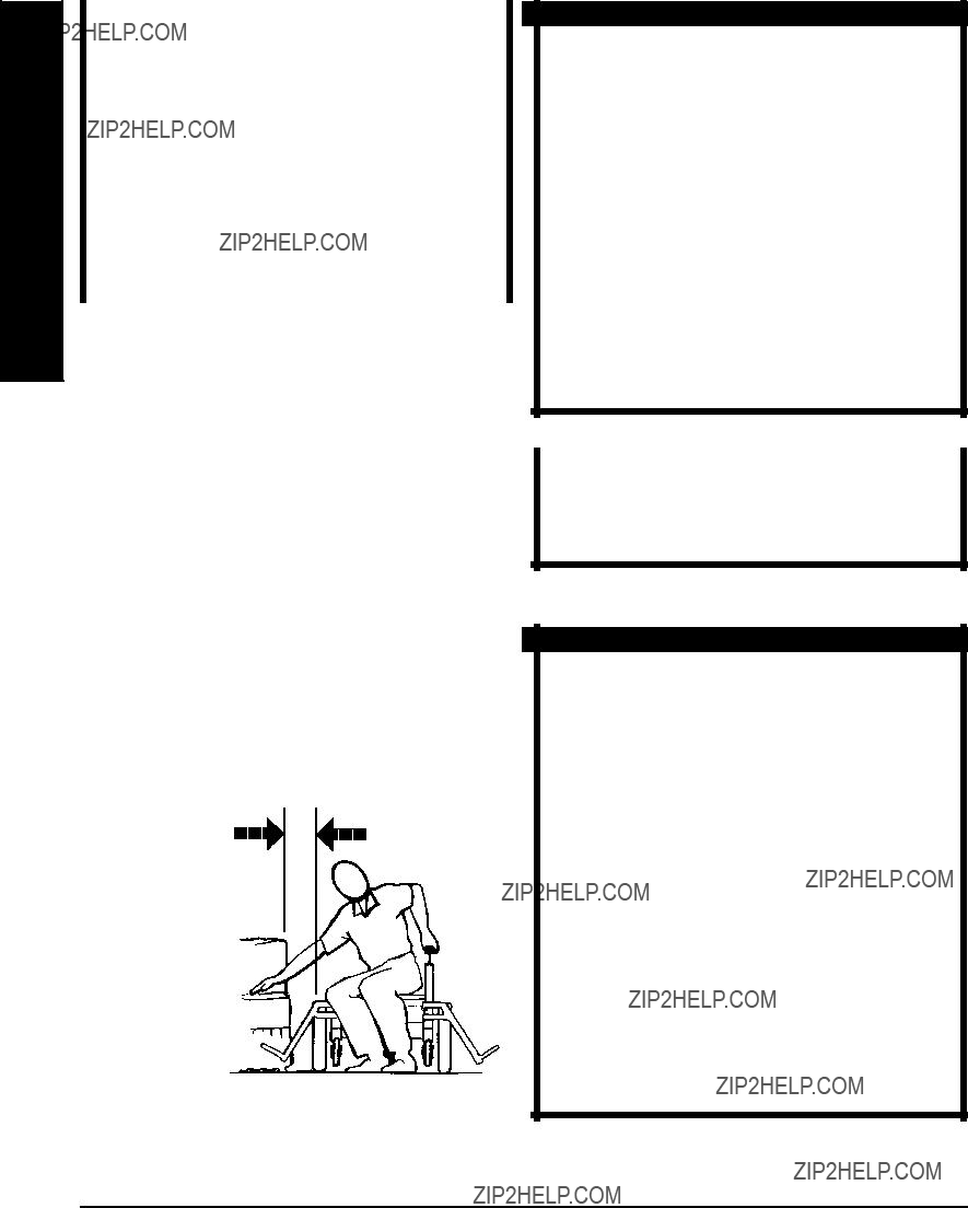
DO NOT attempt to reach objects if you have to move forward in the seat or pick them up from the floor by reaching down between your knees.
Manyactivitiesrequirethewheelchairusertoreach, bend and transfer in and out of the wheelchair. These movements will cause a change to normal balance, center of gravity, and weight distribution of the wheelchair.To determineandestablishyour particular safety limits, practice bending, reaching and transferring activities in several combinations in the presence of a qualified healthcare profes- sional BEFORE attempting active use of the wheel- chair.
Proper positioning is essential for your safety. When reaching, leaning, bending or bending forward, it isimportanttousetherearcastersasatooltomain- tain stability and balance.
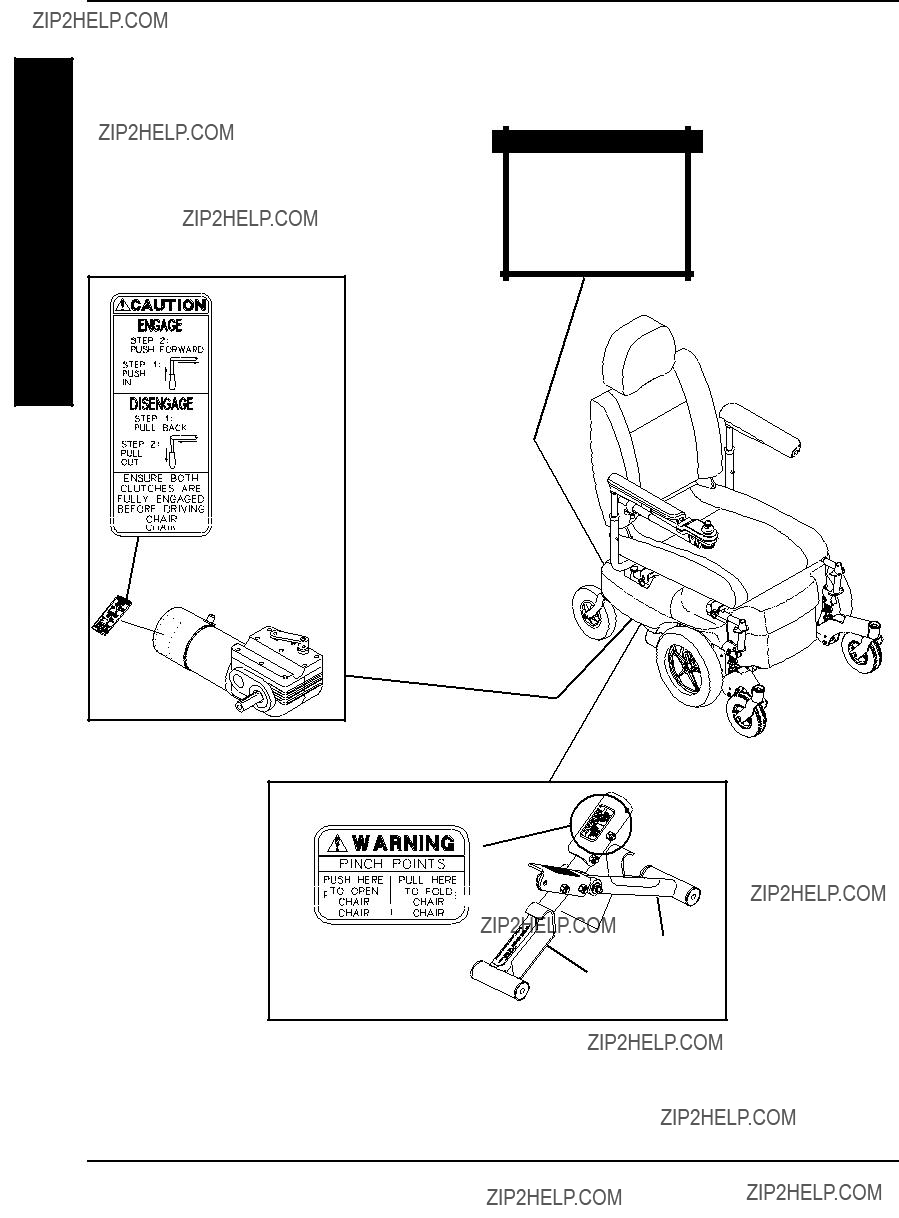
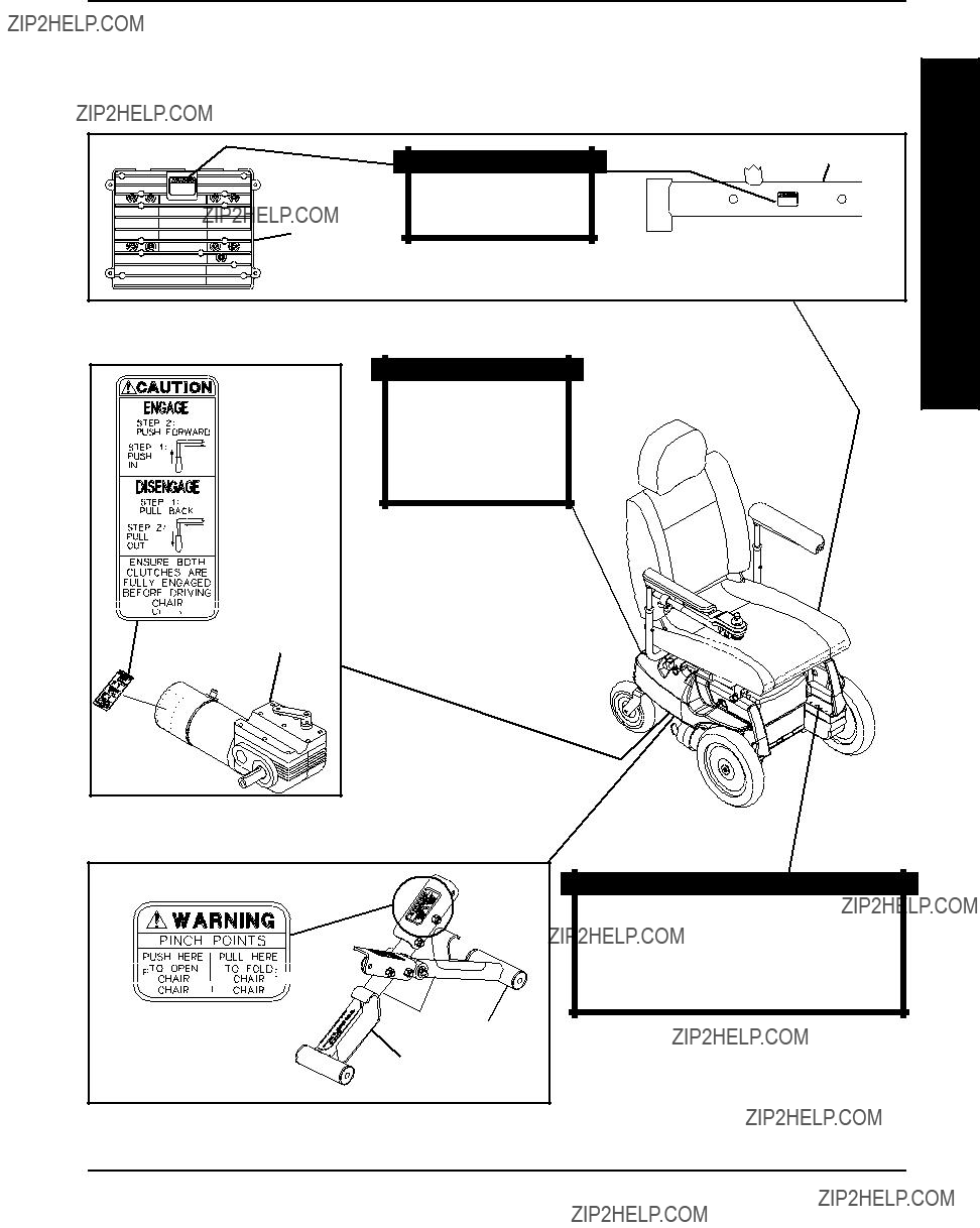
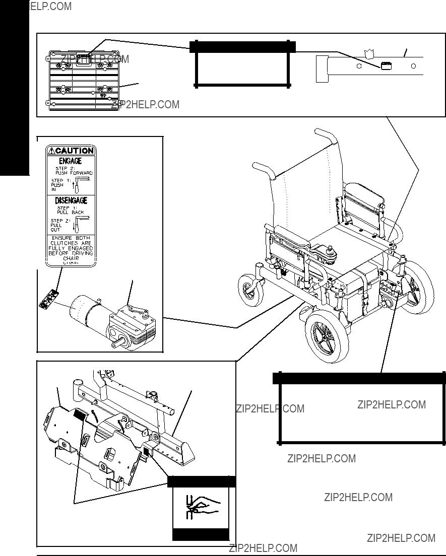
RII MWD WHEELCHAIRS ONLY.
A.WHEELCHAIRS WITH MOTORS THAT HAVE torsrearwardWILLreducethestabilityofthewheel- CLUTCHES - ENGAGING/DISENGAGING chair. This procedure MUST be performed by an
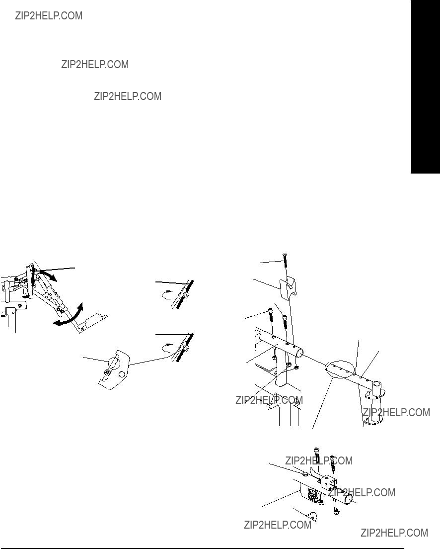
FACTORY SETTINGS - MOTOR MOUNTING POSITIONS
(MOTORS WITH MOTOR LOCKS)
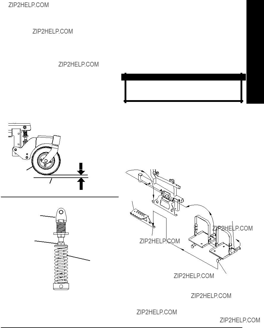
FIGURE 1 shows the motor mounting positions.
FRONT MOTOR
MOUNTING POSITION
FACTORY SETTINGS - MOTOR MOUNTING POSITIONS
(MOTORS WITH CLUTCHES)
USERS' WEIGHT 200 LBS AND UNDER -
MOTOR MOUNTING POSITIONS
USERS' WEIGHT 201 TO 250 LBS -
MOTOR MOUNTING POSITIONS
USERS' WEIGHT 251 TO 300 LBS
(FWD MOTORS WITH MOTOR LOCKS ONLY)-
MOTOR MOUNTING POSITIONS
MIDDLE MOTOR
MOUNTING POSITION
REAR MOTOR
MOUNTING POSITION
FIGURE 1 - PERCENTAGE OF WEIGHT DISTRIBUTION -
FWD WHEELCHAIRS ONLY
Functional Reach From a Wheelchair
The approximate reach-limit values shown in the accompa- nying graphs were derived on the basis of a sample of 91 male and 36 female wheelchair users. Note the difference between the maximum and the comfortable reach limits, a subjective but important consideration in design.
*NOTE: 14 wide is only for RANGER IIJR.
Reaching, Leaning, Bending and Bending -
Forward
Position the rear casters so that they are extended as far rearward as possible and engage motor locks/ clutches. DO NOT ATTEMPT TO REACH OBJECTS
IF YOU HAVE TO MOVE FORWARD IN THE SEAT
OR PICK THEM UP FROM THE FLOOR BY REACH-
ING DOWN BETWEEN YOUR KNEES.

WARNING
CAUTION: IT IS VERY IMPORTANT THAT YOU READ THIS INFORMATION REGARDING THE POSSIBLE EFFECTS
OF ELECTROMAGNETIC INTERFERENCE ON YOUR POWERED WHEELCHAIR.
Electromagnetic Interference (EMI) From Radio Wave sources
Powered wheelchairs and motorized scooters (in this text, both will be referred to as powered wheel- chairs) may be susceptible to electromagnetic interference (EMI), which is interfering electromag- netic energy (EM) emitted from sources such as radio stations, TV stations, amateur radio (HAM) trans- mitters, two way radios, and cellular phones. The interference (from radio wave sources) can cause the powered wheelchair to release its brakes, move by itself, or move in unintended directions. It can also permanently damage the powered wheelchair's control system. The intensity of the interfering EM energy can be measured in volts per meter (V/m). Each powered wheelchair can resist EMI up to a certain intensity. This is called its "immunity level." The higher the immunity level, the greater the protection. At this time, current technology is capable of achieving at least a 20 V/m immunity level, which would provide useful protection from the more common sources of radiated EMI. This powered wheelchair model as shipped has an unknown immunity level.
There are a number of sources of relatively intense electromagnetic fields in the everyday environ- ment. Some of these sources are obvious and easy to avoid. Others are not apparent and exposureis unavoidable. However, we believe that by following the warnings listed below, your risk to EMI will be minimized.
The sources of radiated EMI can be broadly classified into three types:
1)Hand-held Portable transceivers (transmitters-receivers with the antenna mounted directly on the transmitting unit. Examples include: citizens band (CB) radios, "walkie talkie", security, fire and police transceivers, cellular telephones, and other personal communication devices. **NOTE: Some cellular telephones and similar devices transmit signals while they are ON, even when not being used;
2)Medium-range mobile transceivers, such as those used in police cars, fire trucks, ambulances, and taxis. These usually have the antenna mounted on the outside of the vehicle; and
3)Long-range transmitters and transceivers, such as commercial broadcast transmitters (radio and TV broadcast antenna towers) and amateur (HAM) radios.
NOTE: Other types of hand-held devices, such as cordless phones, laptop computers, AM/FM radios, TV sets, CD players, cassette players, and small appliances, such as electric shavers and hair dryers, so far as we know, are not likely to cause EMI problems to your powered wheelchair.
GENERAL GUIDELINESPROCEDURE 1


 1074126
Motor
Assembly
CAUTION
Repositioning the motors WILL affect the stability and/or performance of the wheelchair. Refer to PERCENTAGE OF WEIGHT DISTRIBUTION in the Owner's Manual BEFORE repositioning motors.
1080267
BATTERY BOX SHIPPING INSERTS
REMOVING BATTERY BOX
SHIPPING INSERTS (RANGER II 250 SERIES ONLY) (FIGURE 1)
NOTE: Wheelchairs ordered with batteries installed have shipping inserts which must be removed before using the wheelchair.
1.Remove the battery boxes from the wheelchair. Refer to INSTALLING/REMOVING BATTERY BOXES in PROCEDURE 11 (RWD) or PROCE- DURE 12 (MWD) of this manual.
2.Lift up on the shipping inserts to remove from the battery boxes
3.Install the battery boxes onto the wheelchair. Re- fer to INSTALLING/REMOVING BATTERY BOXES in PROCEDURE 11 (RWD) or PROCE- DURE 12 (MWD) of this manual.
SHIPPING INSERT INSTALLED
Shipping Insert
Shipping
Insert
Battery
Box
Battery Box
SHIPPING INSERT REMOVED
NOTE: Battery box lid not shown for clarity.
FIGURE 1 - REMOVING BATTERY BOX SHIPPING INSERTS
G
E
N
E
R
A
L
G
U
I
D
E
L
I
N
E
NOTE: For additional troubleshooting information and explanation of error codes, refer to the individual CONTROL- LER MANUAL supplied with each wheelchair.
CHECKING BATTERY CHARGE LEVEL
The following ???Do???s??? and ???Don???ts??? are provided for your convenience and safety.
SAFETY INSPECTION CHECKLIST
Initial adjustments should be made to suit personal body structure and preference. Thereafter follow these maintenance procedures:
NOTE: Every six (6) months take your wheelchair to a qualified dealer for a thorough inspection and servicing. Regular cleaningwill reveal loose or worn parts and enhance the smooth operation of your wheelchair. To operate properly and safely, your wheelchair must be cared for just like any other vehicle. Routine maintenance will extend the life and efficiency of your wheelchair.
2.Move the removablefootboardtoone(1)ofthe four(4) positions.
NOTE: Before reinstalling the four (4) flat head screws, make sure the footplate clamps are in the proper position as shown in DETAIL "A".
3.Reinstall the four (4) flat head screws and barrel nuts that secure the removable footboard to the two (2) footplate clamps. Tighten securely.
Angle
ADJUSTING FOOTBOARD ANGLE - ALL MODELS (FIGURE 9).
1.Loosen,butdonotremove,thefour(4)flatheadscrews and barrel nuts that secure the removable footboard to the two (2) footplate clamps.
NOTE: Because of the two (2) support tubes, the angle of the removable footboard can be adjusted down- ward ONLY.
2.Grasp the front of the removable footboard and ro- tate it DOWNWARD until the desired angle is reached.
3.While holding the removable footboard in place, tighten the four (4) flat head screws and barrel nuts securely.
Screw
Footplate
FIGURE 9 - ADJUSTING FLIP-UP
REMOVABLE FOOTBOARD - ADJUSTING
FOOTBOARD ANGLE
FIGURE 8 - ADJUSTING FLIP-UP
REMOVABLE FOOTBOARD - DEPTH

This Procedure Includes the Following:
Installing/Removing Flip Back Armrests
Adjusting Flip Back Armrests
Adjusting Captain's Seat Armrests
WARNING
After ANY adjustments, repair or service and BE- FORE use, make sure all attaching hardware is tightened securely - otherwise injury or damage may result.
INSTALLING/REMOVING FLIP BACK
ARMRESTS (FIGURE 1)
NOTE: Flip back armrests are available on integrated sling seat model wheelchairs only.
WARNING
Make sure the flip back armrest release and height adjustment levers are in the locked posi- tion before using the wheelchair.
NOTE:Flipbackarmrestreleaselevermustbeinunlocked position when placing armrest into the arm sockets.
Installing
1.Slide the flip back armrest into the arm sockets on the wheelchair frame.
2.Installthequickreleasepinthroughthereararmsocket and flip back armrest.
Flip Back Armrest
Release Lever
3.Lock flip back armrest by pressing flip back armrest release lever into the DOWN (VERTICAL) position.
4.Lift up on flip back armrest to make sure the armrest is locked in place.
5.Repeat STEPS 1-4 for opposite flip back armrest.
Removing
1.Unlock flip back armrest by pulling flip back armrest release lever into the UP (HORIZONTAL) position.
2.Remove the quick release pin that secures the flip back armrest to the wheelchair frame.
3.Pull up on the flip back armrest and remove the arm- rest from the arm sockets.
4.Repeat STEPS 1-3 for the opposite flip back arm- rest, if necessary.
ADJUSTING FLIP BACK ARMRESTS (FIGURE 2)
NOTE: Flip back armrests are available on integrated sling seat model wheelchairs only.
Positioning Flip Back Armrests for User Transfer
1.Unlock the flip back armrest by pulling the armrest release lever into the UP (HORIZONTAL) position.
2.Pullupontheflipbackarmrestandremovethearmrest from the front arm socket.
3.Continue to pull up on the flip back armrest until the armrest is out of the way.
4.Repeat STEPS 1-3 for opposite flip back armrest, if necessary.
Top of the Flip Back Armrest LOCKED (DOWN -
VERTICAL)
FIGURE 1 - INSTALLING/REMOVING FLIP BACK
ARMRESTS
Adjusting
1.Unlock top of flip back armrest by pulling height ad- justment lever into the UP (HORIZONTAL) position.
2.Adjusttopoftheflipbackarmresttothedesiredheight.
3.Lock top of flip back armrest by pushing height ad- justment lever into the DOWN (VERTICAL) position.
4.Lift up on flip back armrest to make sure the armrest is locked in place.
5.Repeat STEPS 1-4 for opposite flip back armrest, if necessary.
6.Repeat STEPS 1-5 for opposite armrest, if neces- sary.
Height (FIGURE 4)
1.Remove the socket screw that secures the armrest to the seat frame assembly.
2.Adjust the armrest to one (1) of four (4) positions.
3.Reinstall the socket screw that secures the armrest to the seat frame assembly and tighten securely.
Armrest
Height
Adjustment
Holes
Seat Frame
Assembly
 Socket Screw
FIGURE 4 - ADJUSTING CAPTAIN'S SEAT ARMRESTS -
HEIGHT
ADJUSTING CAPTAIN'S SEAT
ARMRESTS
Angle (FIGURE 3)
1.Lift-up the armrest.
2.Loosen the jam nut.
3.Adjust the socket screw up or down to the desired arm angle position.
4.Tighten the jam nut.
5.To determine the same angle for the opposite arm- rest, count the exposed threads after the jam nut has been tightened.
Jam Nut
Count Exposed Threads
FIGURE 3 - ADJUSTING CAPTAIN'S SEAT ARMRESTS -
ANGLE
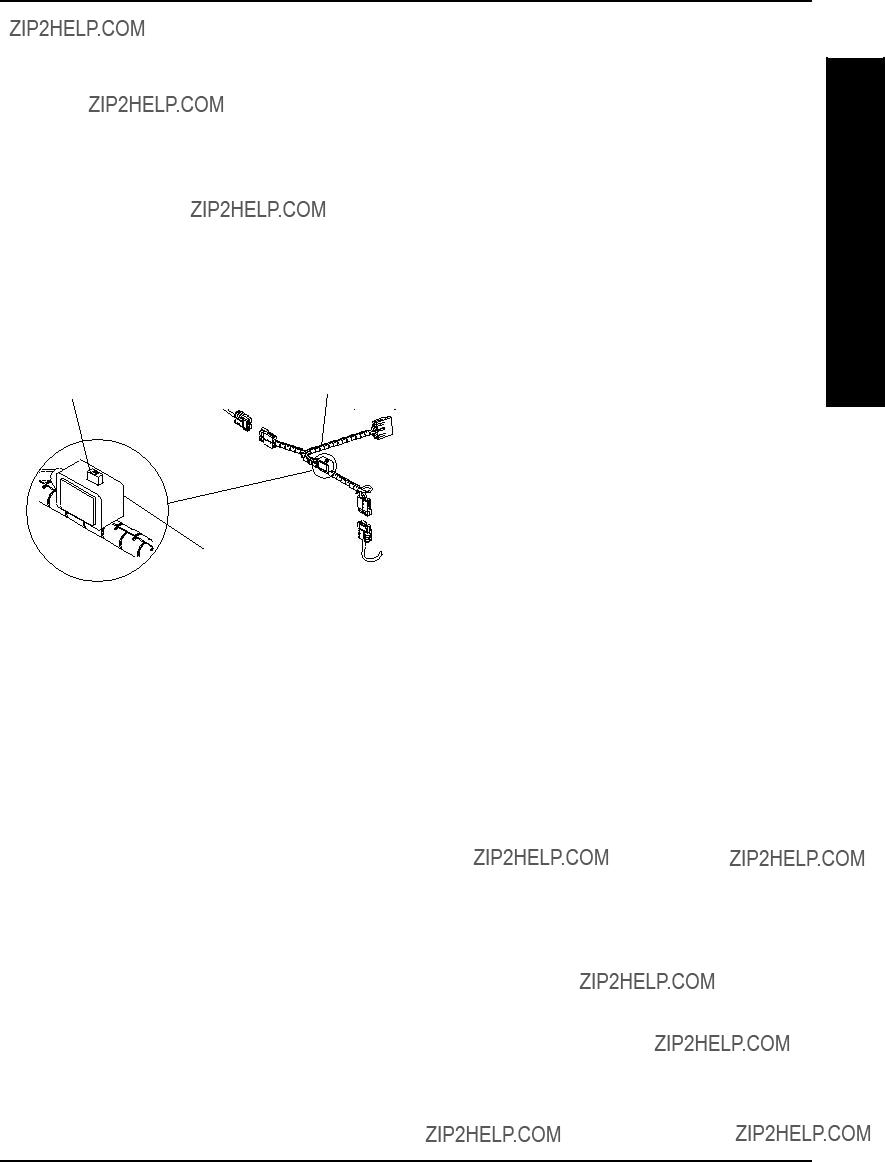
FIGURE 4 - REPOSITIONING BATTERY CHARGER
CONNECTOR

S(FIGURE 1)
T1. If necessary, remove the front and rear shrouds. Refer
P2. Remove the battery boxes from the wheelchair. Refer to one (1) of the following:
FWD WHEELCHAIRS - INSTALLING/REMOVING
BATTERYBOXESinPROCEDURE11ofthismanual.
MWD WHEELCHAIRS - INSTALLING/REMOVING
BATTERYBOXESinPROCEDURE12ofthismanual.
WARNING
The retaining strap MUST be fed through the ad- justable end of the battery box retaining strap clip as shown in FIGURE 1.
3.Feedtheexistingbatteryboxretainingstrapthroughthe adjustable end of the battery box retaining strap buckle.
4.Feed the existing battery box retaining strap through the slot in the battery box tray.
5.Feed the new battery box retaining strap through the inside of the slot in the battery box tray.
6.Feed the new battery box retaining strap through the adjustableendofthebatteryboxretainingstrapbuckle.
NOTE: Strap should have 3/4-inch length minimum beyond buckle.
7.Install the battery boxes onto the wheelchair. Refer to one (1) of the following:
FWD WHEELCHAIRS - INSTALLING/REMOVING BATTERYBOXESinPROCEDURE11ofthismanual.
MWD WHEELCHAIRS - INSTALLING/REMOVING BATTERYBOXESinPROCEDURE12ofthismanual.
WARNING
The Battery Box Retaining Strap MUST be fastened securely and adjusted properly to hold battery boxes in place before using the wheelchair. Oth- erwise, injury to the user and/or damage to the wheelchair may occur.
8.If necessary, install the front and rear shrouds. Refer toREMOVING/INSTALLINGSHROUDSinPROCE- DURE 9 of this manual.
NOTE: Tray shown by itself for clarity. There is no need to remove the tray from the wheelchair if the retaining strap is being replaced.
NOTE: RANGER IIJR battery tray not shown for clarity. Retaining strap removes/installs in the same manner.
FIGURE 1 - REPLACING BATTERY BOX RETAINING
STRAP - ALL MWD MODELS AND FWD MODEL -
RANGER IIJR
FIGURE 2 - REMOVING/INSTALLING SHROUDS - FWD WHEELCHAIRS
Positive (+) Battery
Terminal/Post
CONNECT
BATTERY
CABLE(S) RING
TERMINAL(S) TO
THIS SIDE OF
BATTERY
TERMINAL(S)/
POST(S)
DETAIL ???B???
DUAL GROUP 22 NF BATTERIES
POSITIVE (+) Battery Terminal/Post
1/4-20 x 7/8-Inch POSITIVE (+) RedHex Flange Screw
Battery Cable
1/4-20 Hex Flange Locknut
NEGATIVE (-) Battery
Terminal/Post
CONNECT BATTERY
CABLE TO BATTERY
TERMINAL AS SHOWN.
DUAL GROUP 22 NF BATTERIES
Tie-
Wrap
Group 22 NF BLACK BatteryTerminal
BatteryCap
FIGURE 3 - CONNECTING BATTERY CABLES - DIRECT MOUNT METHOD

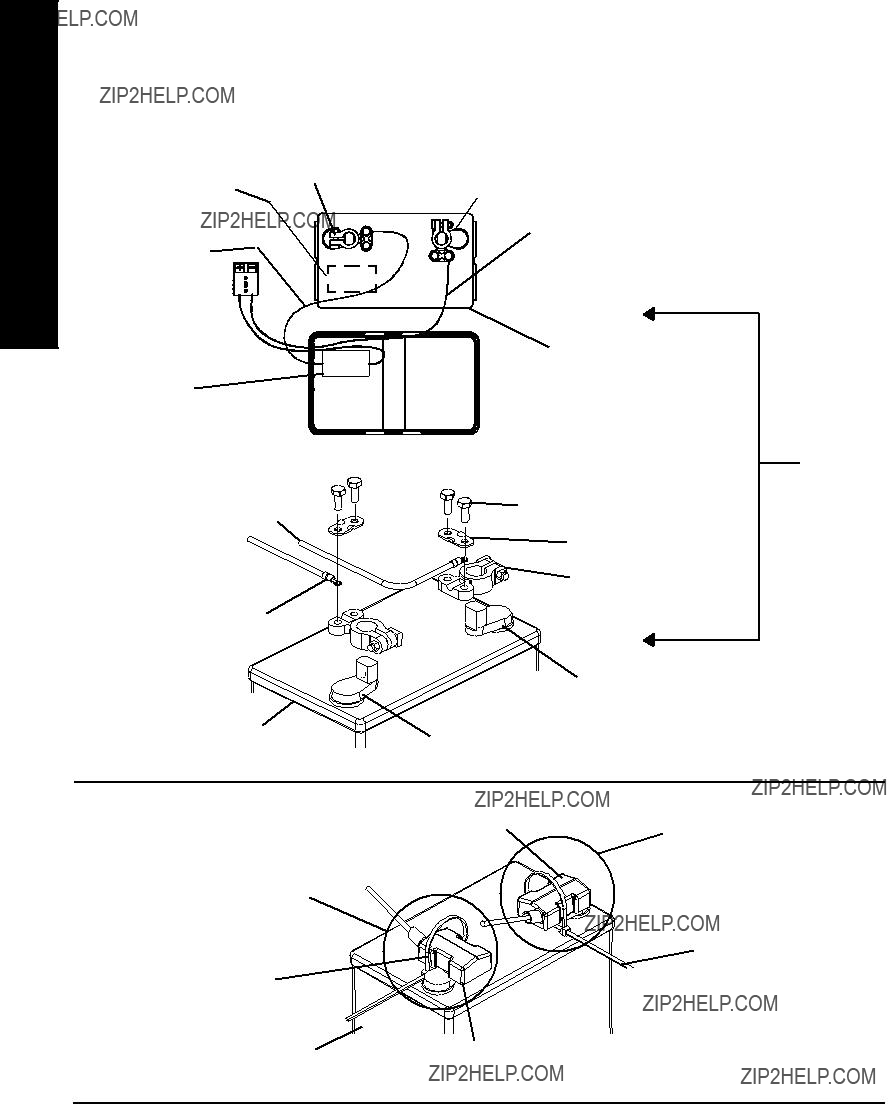
BATTERY CLAMP METHOD (FIGURES 4, 5 AND 6).
CAUTION
The battery clamp of the POSITIVE (+) battery terminal/post MUST be mounted in the posi- tion shown in FIGURE 5, otherwise the battery box top cannot be installed properly.
1.Perform one (1) of the following:
A.If the battery clamp of the POSITIVE (+) battery terminal/post is NOT mounted in the orientation shown in FIGURE 5, perform the following:
???Loosenthehexnutthatsecuresthebatteryclamp to the POSITIVE (+) battery terminal/post.
CAUTION
When tightening the clamps, always use a box wrench. Pliers will ???round off??? the nuts. NEVER wiggle the battery terminal(s)/post(s) when tightening. The battery may become damaged.
???Remove the battery clamp from the POSI- TIVE (+) battery terminal/post.
???Reposition the battery clamp on the POSI- TIVE (+) battery terminal/post as shown in FIGURE 4.
???Securely tighten the hex nut that secures the battery clamp to the positive (+) battery ter- minal/post.
B.If the battery clamp on the POSITIVE (+) battery terminal/post is positioned as shown in FIGURE 4, proceed to STEP 2.
CORRECT ORIENTATION OF THE POSITIVE (+)
BATTERY TERMINAL/POST BATTERY CLAMP
POSITIVE (+) Battery Terminal/Post
(Note position of battery clamp)
2.Install battery clamp covers onto battery cables as follows: (FIGURE 5)
A.RED batteryclampcoverontoREDbatterycable.
B.BLACK battery clamp cover onto BLACK bat- tery cable.
NOTE:Onlyone(1)batterycableandbatteryclampcover are shown for clarity. Both battery clamp covers install in the same manner.
INSTALLING BATTERY CLAMP COVERS
FIGURE 5 - CONNECTING BATTERY CABLES -
BATTERY CLAMP METHOD
CAUTION
Whenconnectingthebatterycable/ringterminal(s) to the battery(ies) clamp(s), the battery cable(s) MUSTbeconnectedinthepositionshowninDETAIL ???A???, otherwise damage may occur to the battery cable and/or battery clamp covers.
NEGATIVE (-) Battery
Terminal/Post and Battery Clamp
Group 22NF
Battery
NOTE:It will benecessarytotrimexcesstie-wrapinorderto install the battery box top(s).
8. Install the battery box top(s).
FIGURE 4 - CONNECTING BATTERY CABLES -
BATTERY CLAMP METHOD
DETAIL ???A???
Mounting Plate
Battery Clamp
EXPLODED
Negative (-) BLACKVIEW
Battery Cable
POSITIVE (+) Battery
Terminal/Post
Group 22NF Battery
NEGATIVE (-) Battery Terminal/Post
NOTE: Battery clamps exploded away for clarification purposes only.
NEGATIVE (-) Battery
Terminal/Post
Tie-Wrap
Tie-Wrap
FIGURE 6 - CONNECTING BATTERY CABLES - BATTERY CLAMP METHOD

4.Removethebatteriesandfootrests/legrests/footboard plate from the wheelchair. Refer to FIGURE 2.
5.Lift the battery tray UP and out of the way. Refer to BATTERY TRAY in this procedure of the manual.
6.Lift up on push brackets located on the crossbraces.
WHEN TO CHARGE BATTERIES (FIGURE 3)
It is advantageous to recharge frequently rather than only when necessary. In fact, a battery???s life is extended if the charge level is maintained well above a low condition.
MKIV RII Joystick
BATTERY DISCHARGE INDICATOR (BDI) is located at the rear of the joystick housing and provides information on the remaining charge in the batteries. At FULL charge theBDIwillbeGREEN.Asthebatterybecomesdischarged, the BDI indicator will turn AMBER (YELLOW), then RED andfinallyFLASHINGRED.IftheBDIisFLASHINGRED, the user should charge the batteries as soon as possible.
NOTE: Accurate readings are displayed when in neutral.
MCC-MKIV X, A or A+ Joystick
BATTERY GAUGE DISPLAY (BGD) is the bar graph dis- play located on the MKIV X, A or A+ joystick. It will keep you informed as to power availability. A visual warning is given before the power becomes too low to operate the wheelchair. At full charge the two (2) LEFT segments and the farthest RIGHT segment of the bar graph will be illumi- nated. As the battery becomes discharged, the farthest RIGHT segment will progressively move to the LEFT until only the last two (2) bars (LEFT) are illuminated. At this level the last two (2) bars (LEFT) will start to Flash ON and OFF to indicate that the end user should charge the batter- ies as soon as possible.
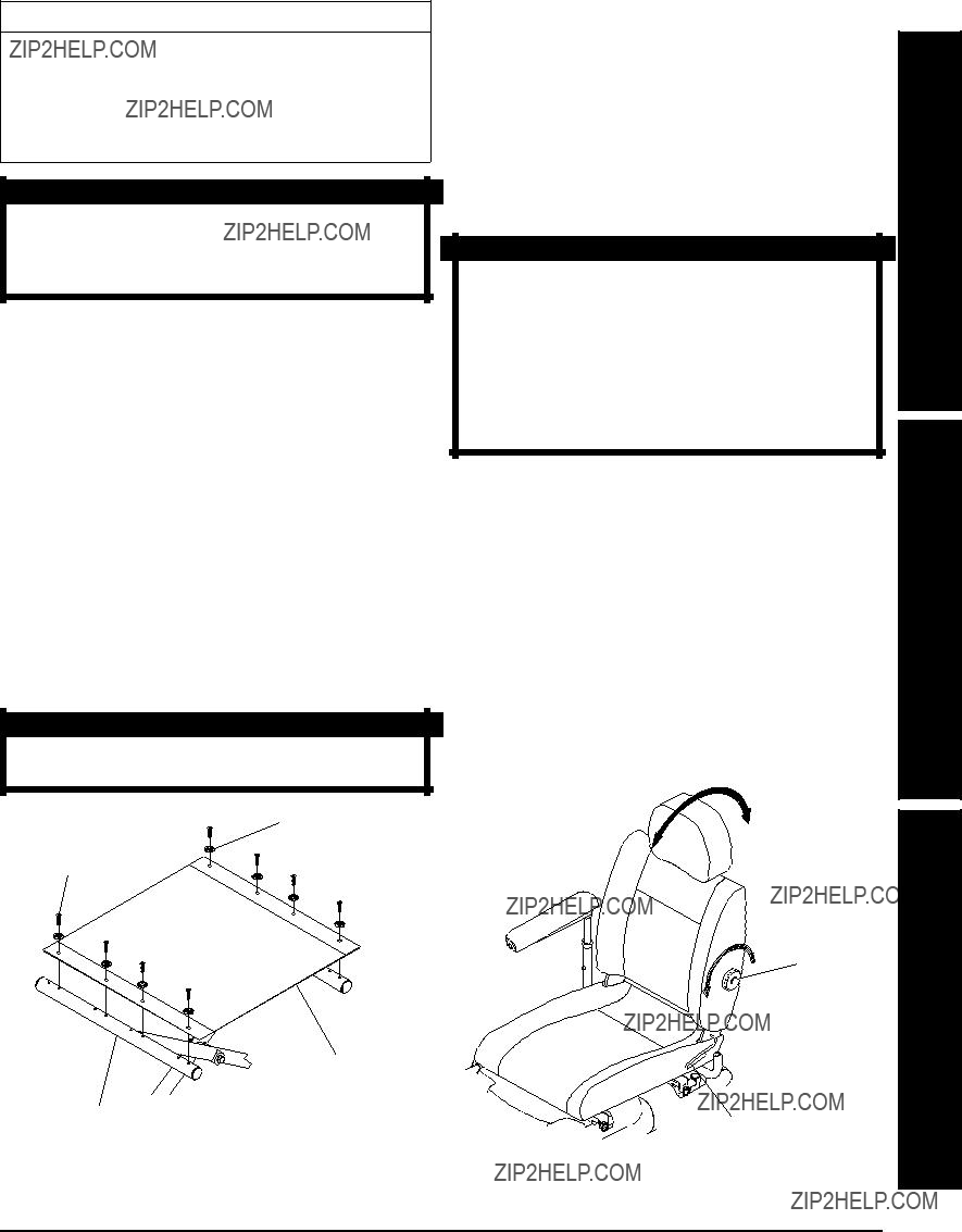
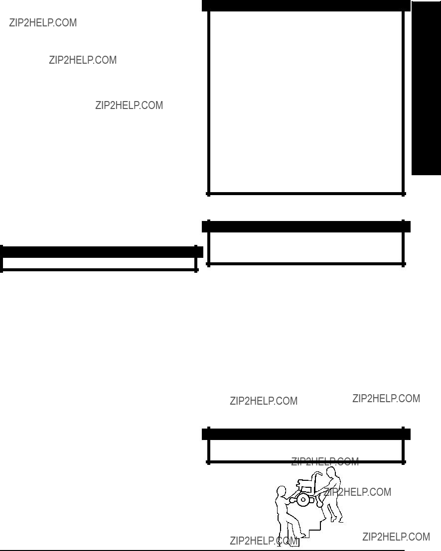
CAUTION
HIGHBACKCAPTAIN'S SEATS ONLY - Discon- nect limit switch BE-
Lift battery tray UP and out of the way. Refer to BATTERY TRAY in this procedure of the manual.
NOTE: Accurate readings are displayed when in neutral.
FORE removing seat - damage to seat can occur.
Disconnect the limit switch. Refer to DISCONNECT-
ING/CONNECTING LIMIT SWITCH in PROCEDURE 6 of this manual.
FIGURE 3- WHEN TO CHARGE BATTERIES
FIGURE 2 - TRANSPORTING RANGER II FWD -
CAPTAIN'S SEATS
3.Position the battery boxes onto the battery tray in the following order:
A.FRONT Battery Box.
B.REAR Battery Box.
4.Position retaining straps around each battery box as shown in DETAIL "A" of FIGURE 7 and clip retaining strap together.
NOTE: Make sure battery box leads are on the same side as battery connectors on wheelchair frame.
5.Connect the battery box leads to the battery con- nectors on the wheelchair frame.
6.If necessary, reinstall the removeable footboard. Refer to PREPARING THE REMOVEABLE
FOOTBOARD FOR WHEELCHAIR TRANSPOR- TATION in PROCEDURE 3 of this manual.
FIGURE 5 - INSTALLING/REMOVING BATTERY BOXES
Battery boxes MUST be installed/removed in the order stated below or the battery tray could rotate causing the rear battery box to fall possibly causing injury or damage.
Use extreme care when installing/removing the battery boxes.
NEVER unplug the battery cables by pulling on the wires. Unplug the battery cables by pull- ing on the connector ONLY. Otherwise injury or damage may result.
When removing the battery boxes from the wheelchair, remove the rear battery box first.
LIMITED WARRANTY
PLEASE NOTE: THE WARRANTY BELOW HAS BEEN DRAFTED TO COMPLY WITH FEDERAL LAW APPLICABLE TO PRODUCTS MANUFACTURED AFTER JULY 4, 1975.
This warranty is extended only to the original purchaser/user of our products.
Thiswarrantygivesyouspecificlegalrightsandyoumayalsohaveotherlegalrightswhichvaryfromstate to state.
With regardsto the original purchaser/useronly,Invacarewarrantsthesideframesandcrossbracestobe free from defects in materials and workmanship for a period of five (5) years from date of purchase; electronics for a period of one (1) year from the date of purchase; motors and gearboxes for a period of eighteen (18) months for Ranger II models with motors that have motor locks and a period of twelve (12) months for Ranger II models with motors that have clutches from the date of purchase; all remaining components (including gas cylinders for recliners) for one (1) year from the date of purchase except upholstered materials, padded materials and tires/wheels. If within such warranty period any product shall be proven to be defective, such product shall be repaired or replaced, at Invacare's option. This warranty does not include any labor or shipping charges incurred in replacement part installation or repairofanysuchproduct. Invacare'ssoleobligationandyourexclusiveremedyunderthiswarrantyshall be limited to such repair and/or replacement.
For warranty service, please contact the dealer from whom you purchased your Invacare product. In the event you do not receive satisfactory warranty service, please write directly to Invacare at the ad- dress on the bottom of the page. Provide dealer's name address, date of purchase, indicate nature of the defect and, if the product is serialized, indicate the serial number. Do not return products to our factory without our prior consent.
LIMITATIONS AND EXCLUSIONS: THE FOREGOING WARRANTY SHALL NOT APPLY TO SERIAL NUMBERED
PRODUCTS IF THE SERIAL NUMBER HAS BEEN REMOVED OR DEFACED, PRODUCTS SUBJECT TO NEGLI-
GENCE,ACCIDENT,IMPROPEROPERATION,MAINTENANCEORSTORAGE,COMMERCIALORINSTITUTIONAL
USE, PRODUCTS MODIFIED WITHOUT INVACARE'S EXPRESS WRITTEN CONSENT INCLUDING, BUT NOT LIM-
ITEDTO,MODIFICATIONTHROUGHTHEUSEOFUNAUTHORIZEDPARTSORATTACHMENTS;PRODUCTSDAM-
AGED BY REASON OF REPAIRS MADE TO ANY COMPONENT WITHOUT THE SPECIFIC CONSENT OF INVAC-
ARE, OR TO A PRODUCT DAMAGED BY CIRCUMSTANCES BEYOND INVACARE'S CONTROL, AND SUCH
EVALUATION WILL BE SOLELY DETERMINED BY INVACARE. THE WARRANTY SHALL NOT APPLY TO PROBLEMS
ARISING FROM NORMAL WEAR OR FAILURE TO ADHERE TO THESE INSTRUCTIONS. A CHANGE IN OPERAT-
ING NOISE, PARTICULARLY RELATIVE TO MOTORS AND GEARBOXES DOES NOT CONSTITUTE A FAILURE. ALL
SUCH DEVICES WILL EXHIBIT A CHANGE IN OPERATING NOISE DUE TO AGING.
THE FOREGOING WARRANTY IS EXCLUSIVE AND IN LIEU OF ALL OTHER EXPRESS WARRANTIES. IMPLIED
WARRANTIES, IF ANY, INCLUDING THE IMPLIED WARRANTIES OF MERCHANTABILITY AND FITNESS FOR A
PARTICULAR PURPOSE, SHALL NOT EXTEND BEYOND THE DURATION OF THE EXPRESSED WARRANTY PRO-
VIDEDHEREIN ANDTHE REMEDYFOR VIOLATIONSOFANYIMPLIEDWARRANTYSHALL BE LIMITED TO REPAIR
OR REPLACEMENT OF THE DEFECTIVE PRODUCT PURSUANT TO THE TERMS CONTAINED HEREIN. INVACARE
SHALL NOT BE LIABLE FOR ANY CONSEQUENTIAL OR INCIDENTAL DAMAGES WHATSOEVER.
THIS WARRANTY SHALL BE EXTENDED TO COMPLY WITH STATE/PROVINCIAL LAWS AND REQUIREMENTS.


 Footrest
 Footrest Support