SECTION 3???EMI INFORMATION
SECTION 3???EMI INFORMATION
� WARNING
CAUTION: IT IS VERY IMPORTANT THAT YOU READ THIS INFORMATION
REGARDING THE POSSIBLE EFFECTS OF ELECTROMAGNETIC
INTERFERENCE ON YOUR POWERED WHEELCHAIR.
Electromagnetic Interference (EMI) From Radio Wave Sources
Powered wheelchairs and motorized scooters (in this text, both will be referred to as powered wheelchairs) may be susceptible to electromagnetic interference (EMI), which is interfering electromagnetic energy (EM) emitted from sources such as radio stations, TV stations, amateur radio (HAM) transmitters, two way radios, and cellular phones. The interference (from radio wave sources) can cause the powered wheelchair to release its brakes, move by itself, or move in unintended directions. It can also permanently damage the powered wheelchair's control system. The intensity of the interfering EM energy can be measured in volts per meter (V/m). Each powered wheelchair can resist EMI up to a certain intensity. This is called its ???immunity level.??? The higher the immunity level, the greater the protection. At this time, current technology is capable of achieving at least a 20 V/m immunity level, which would provide useful protection from the more common sources of radiated EMI.
There are a number of sources of relatively intense electromagnetic fields in the everyday environment. Some of these sources are obvious and easy to avoid. Others are not apparent and exposure is unavoidable. However, we believe that by following the warnings listed below, your risk to EMI will be minimized.
The sources of radiated EMI can be broadly classified into three types:
1)Hand-held Portable transceivers (transmitters-receivers with the antenna mounted directly on the transmitting unit. Examples include: citizens band (CB) radios, ???walkie talkie???, security, fire and police transceivers, cellular telephones, and other personal communication devices. NOTE: Some cellular telephones and similar devices transmit signals while they are ON, even when not being used;
2)Medium-range mobile transceivers, such as those used in police cars, fire trucks, ambulances and taxis. These usually have the antenna mounted on the outside of the vehicle; and
3)Long-range transmitters and transceivers, such as commercial broadcast transmitters (radio and TV broadcast antenna towers) and amateur (HAM) radios.
NOTE: Other types of hand-held devices, such as cordless phones, laptop computers, AM/FM radios, TV sets, CD players, cassette players, and small appliances, such as electric shavers and hair dryers, so far as we know, are not likely to cause EMI problems to your powered wheelchair.


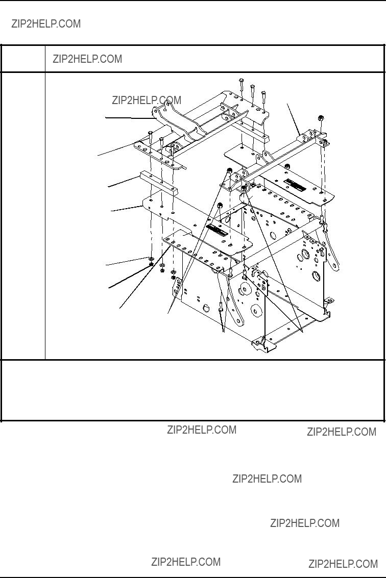


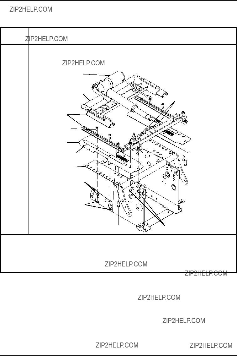


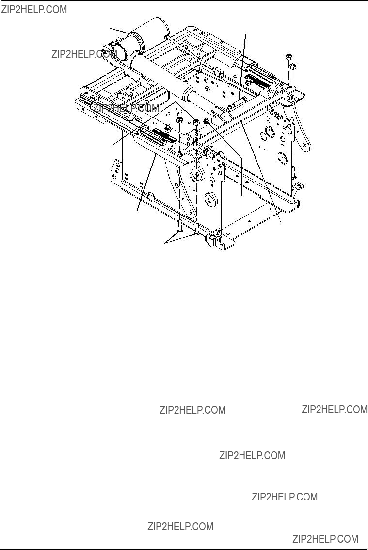


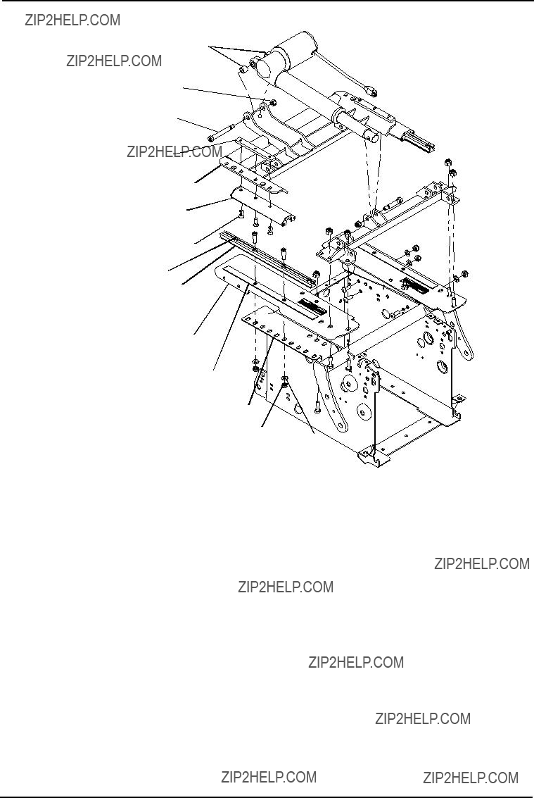
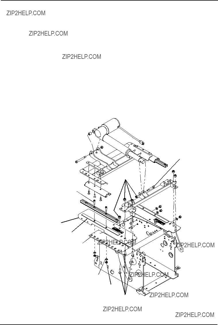
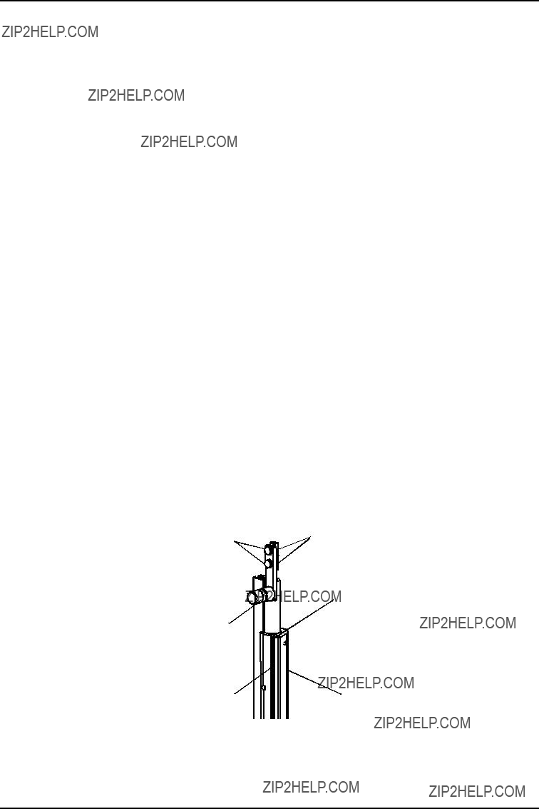
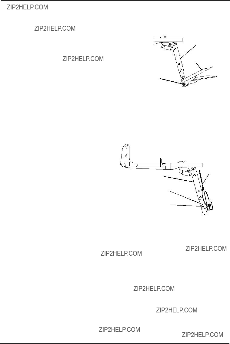
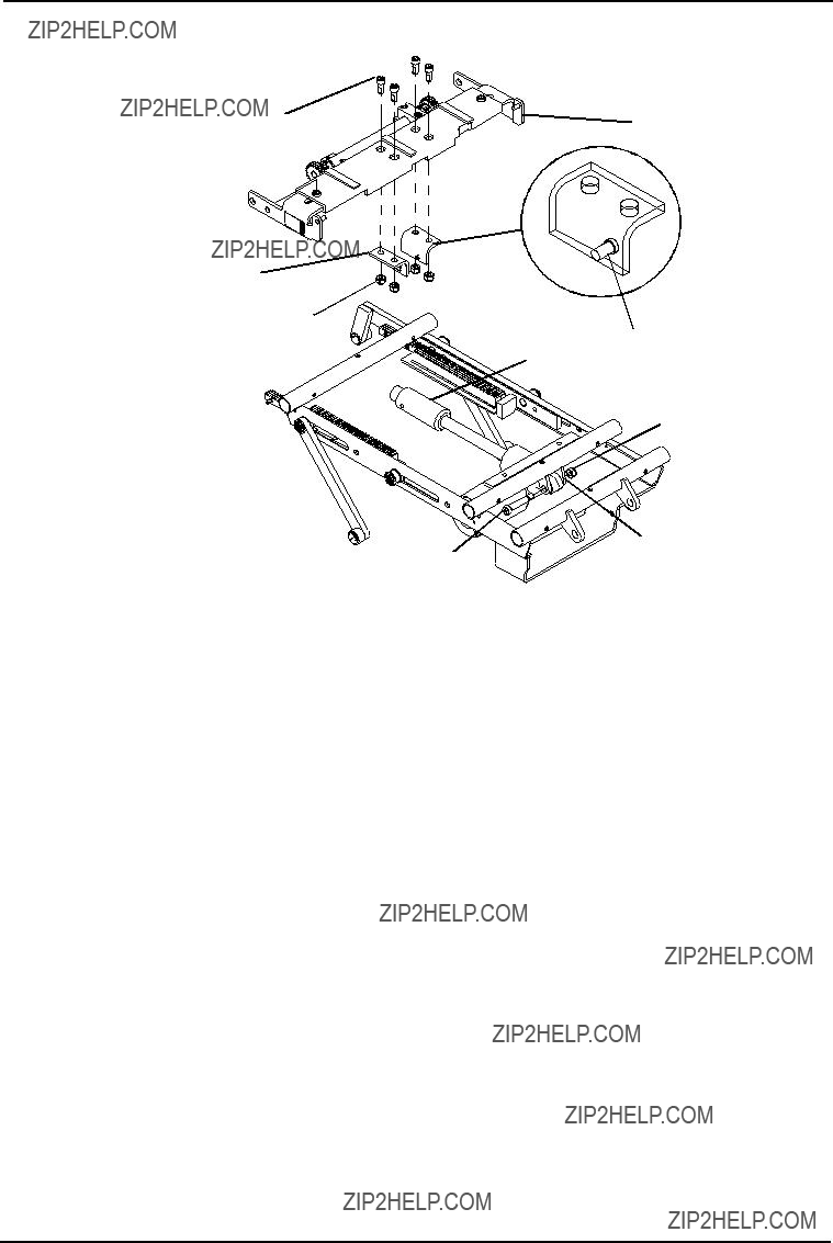
 Tilt Actuator


 Tilt Actuator
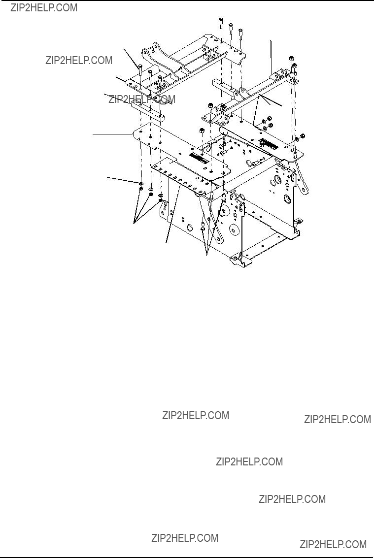


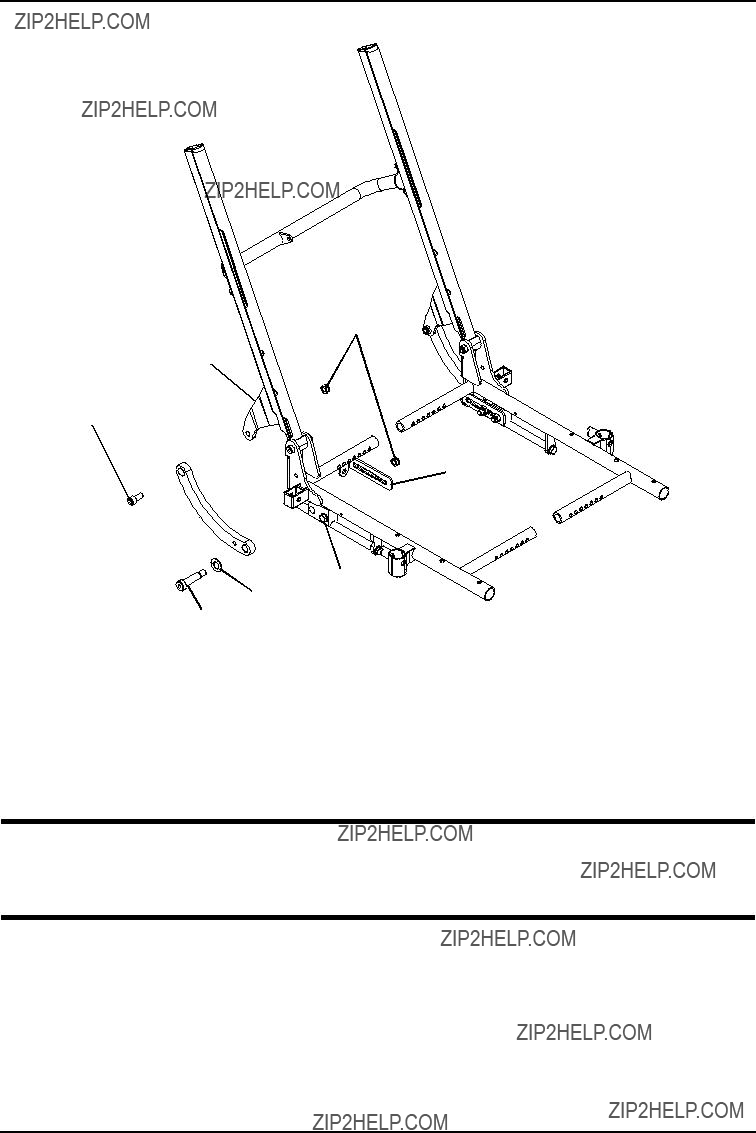
 Mounting Hole for 0??
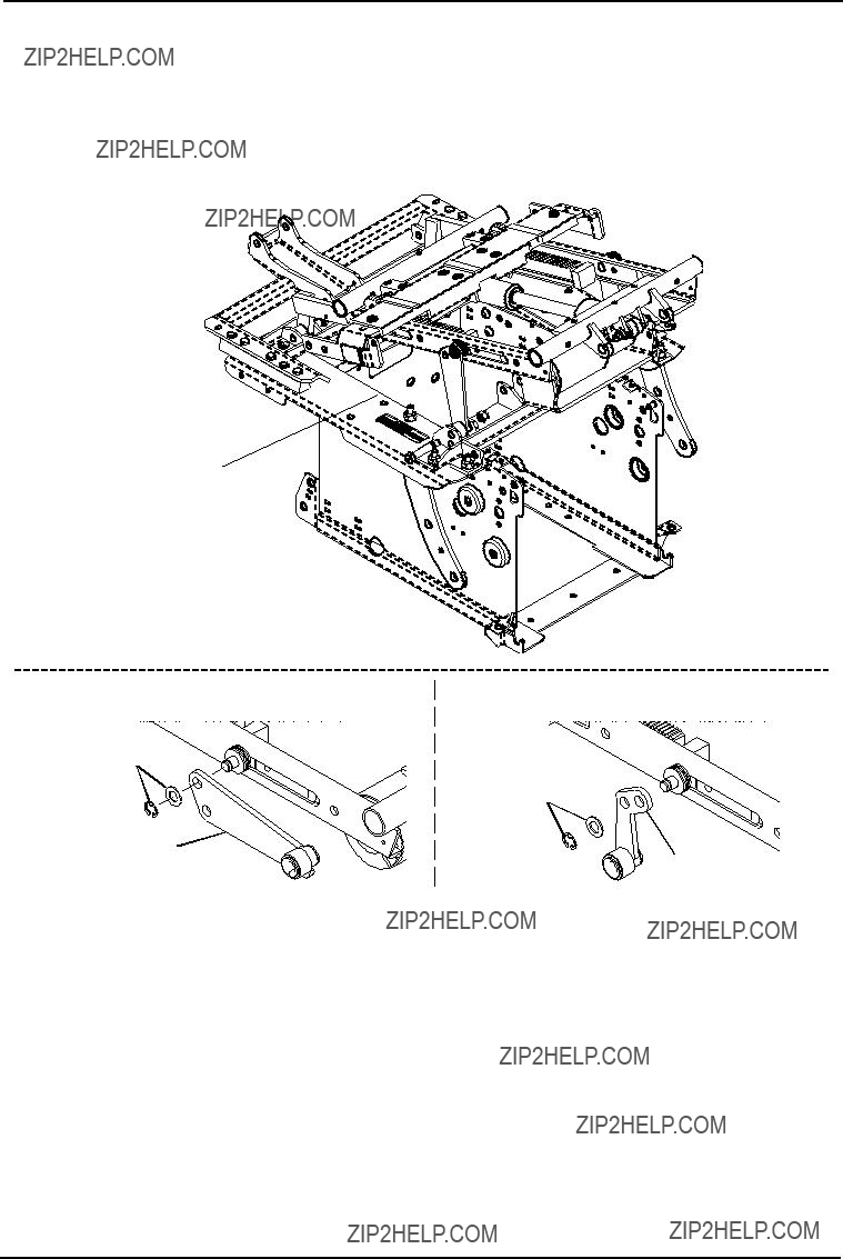


 Ring
Ring
 *Retaining

 Mounting Hole


 Hex Bolts
 Seat Frame


 Locknuts
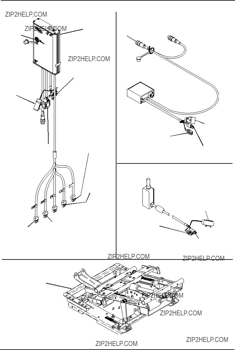


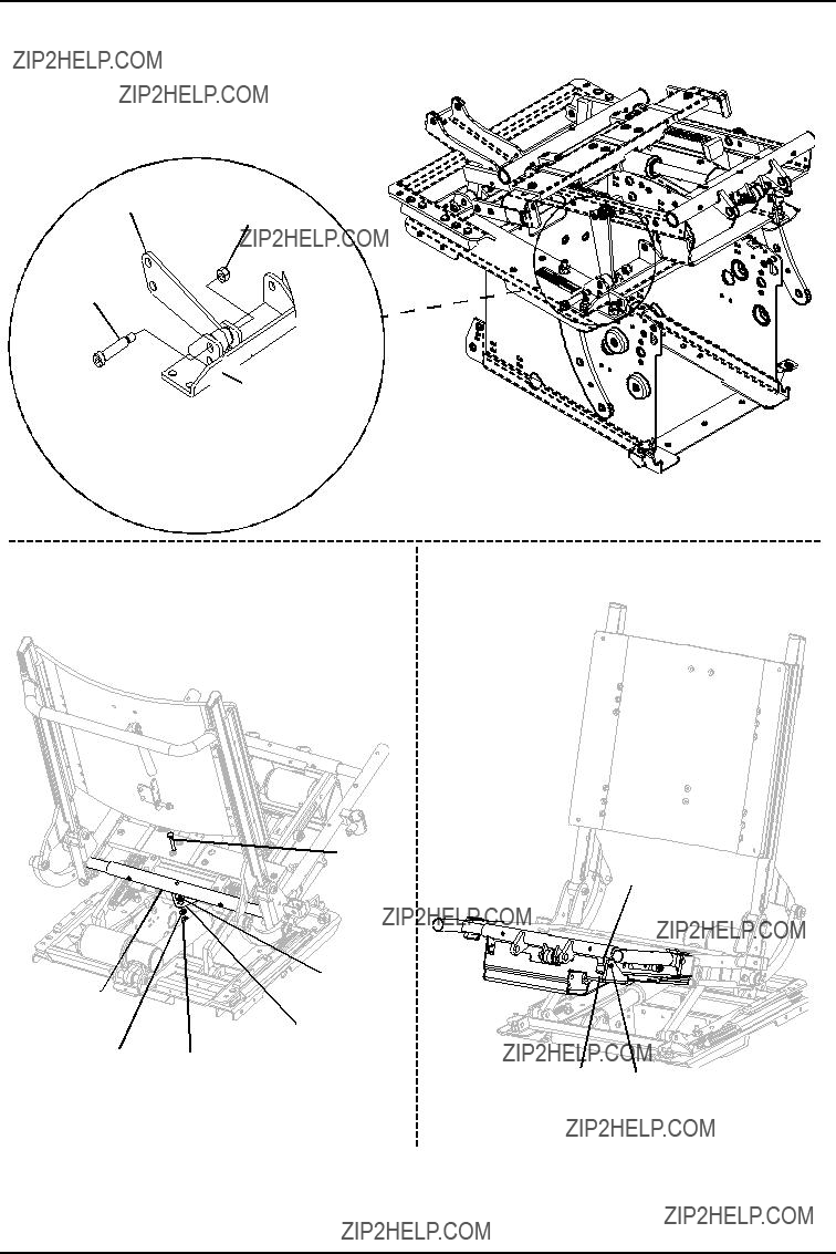
 TRCM or
 Potentiometer
 Actuator
 SAC
SAC
 TRSS
TRSS


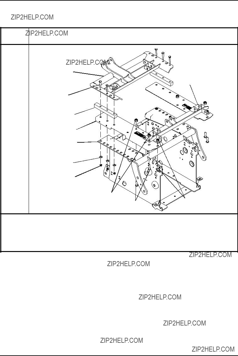
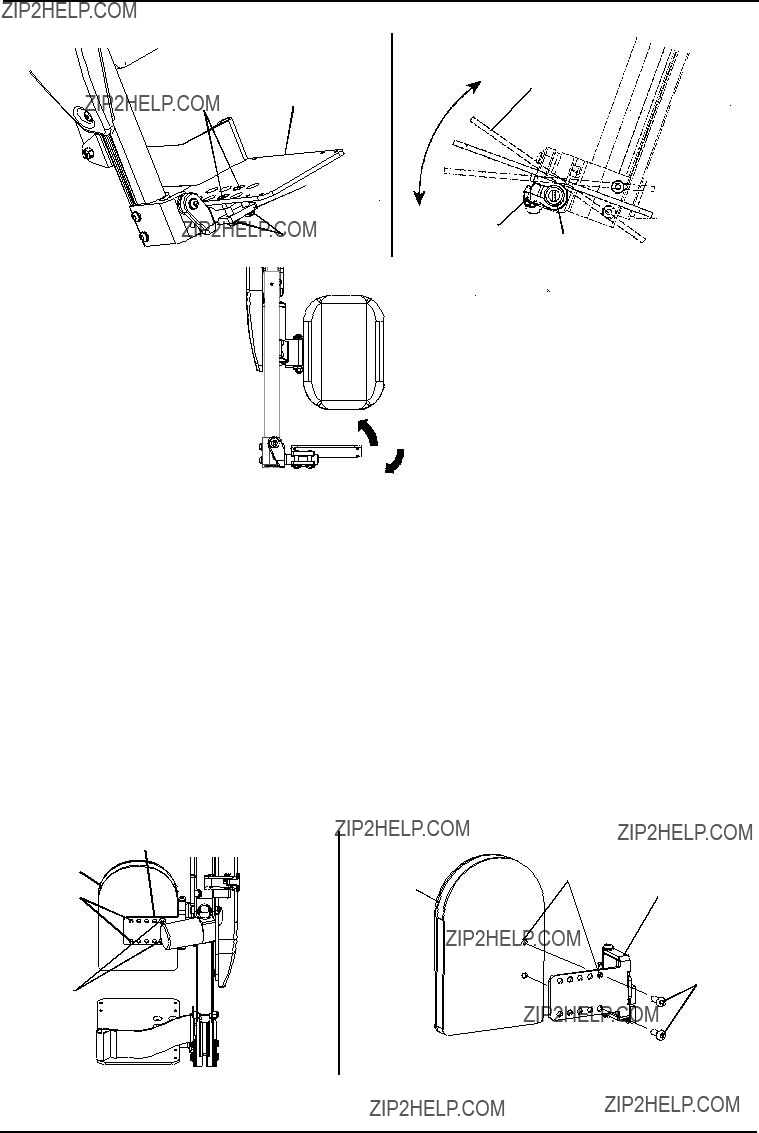
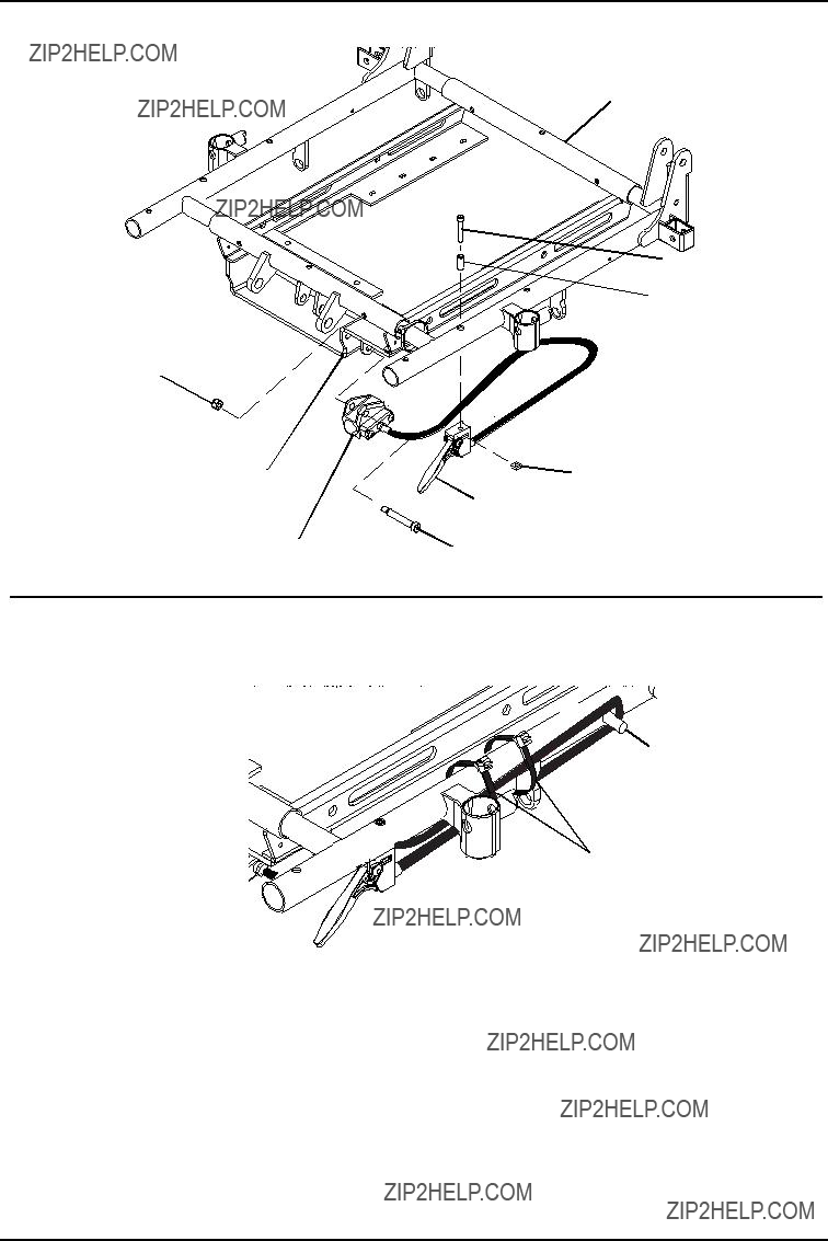
 Mounting Hole for 0?? seat angle
 Use this mounting hole for 0?? seat angle
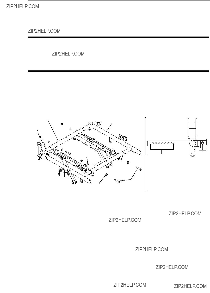
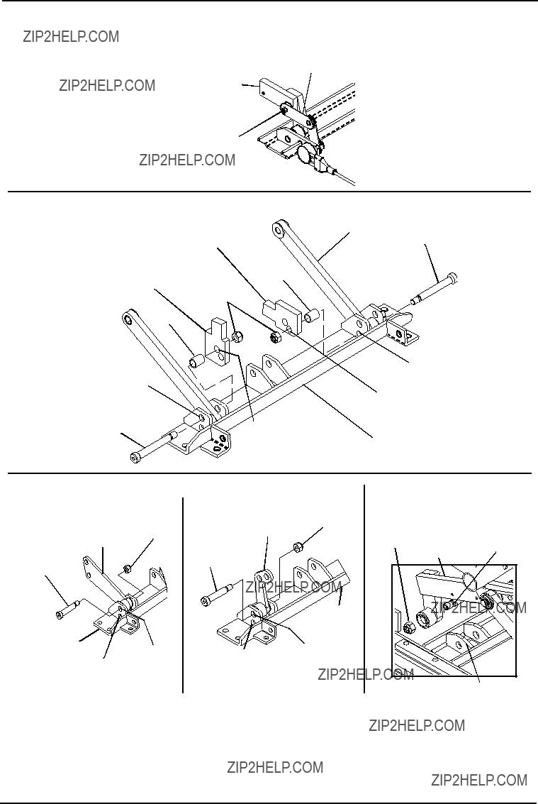
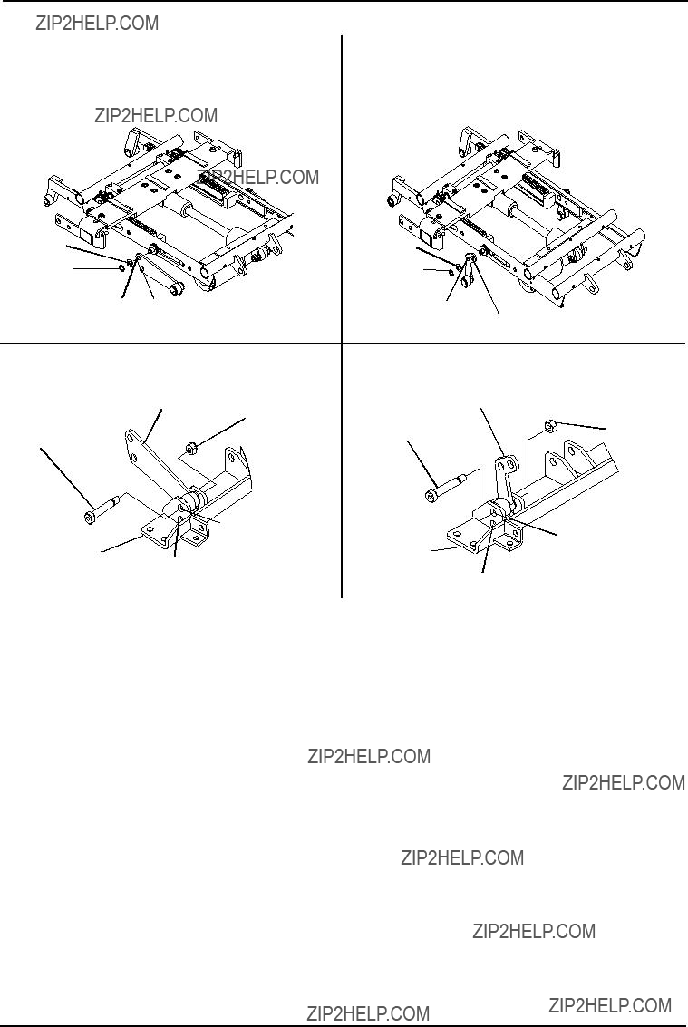
 Front Pivot Assembly


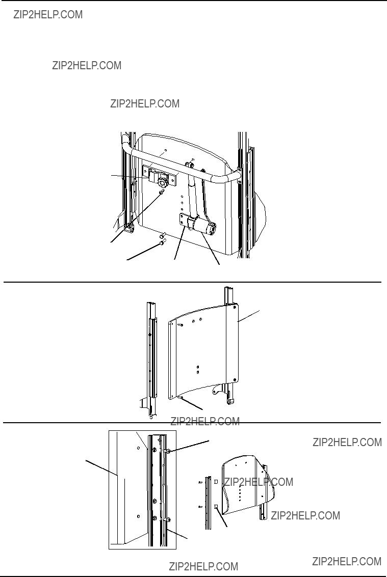


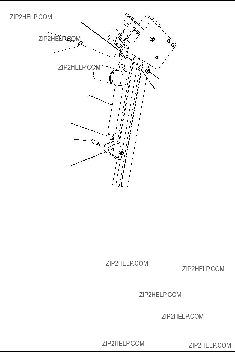
 Back Slide


 Cane
Cane


 T-Nut
T-Nut


 Back Cane


 Lower Seat Shroud


 Assembly


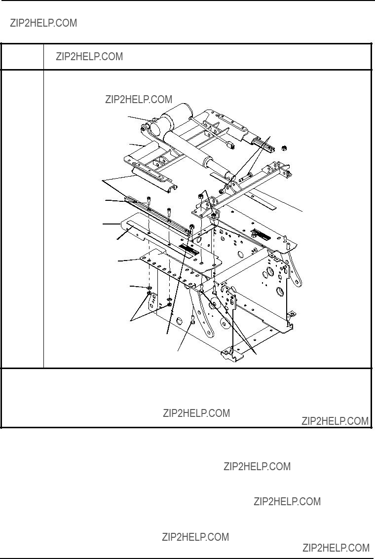
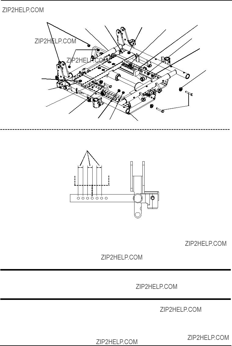
 Set Screw

 Bracket
 Outer Rail

 Outer
Outer


 Locknut


 Release Lever


 Mounting Screw
 Spacer
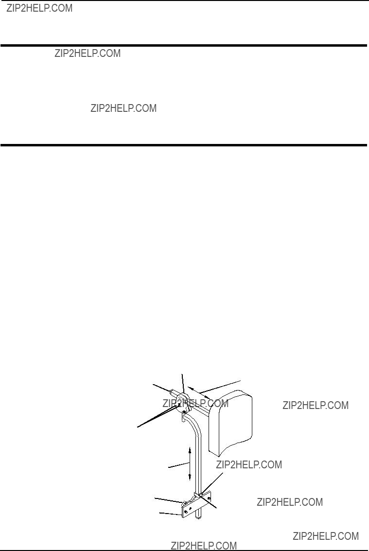


 LED
LED


 Locknut


 Front Pivot

 SAC
SAC SAC
SAC


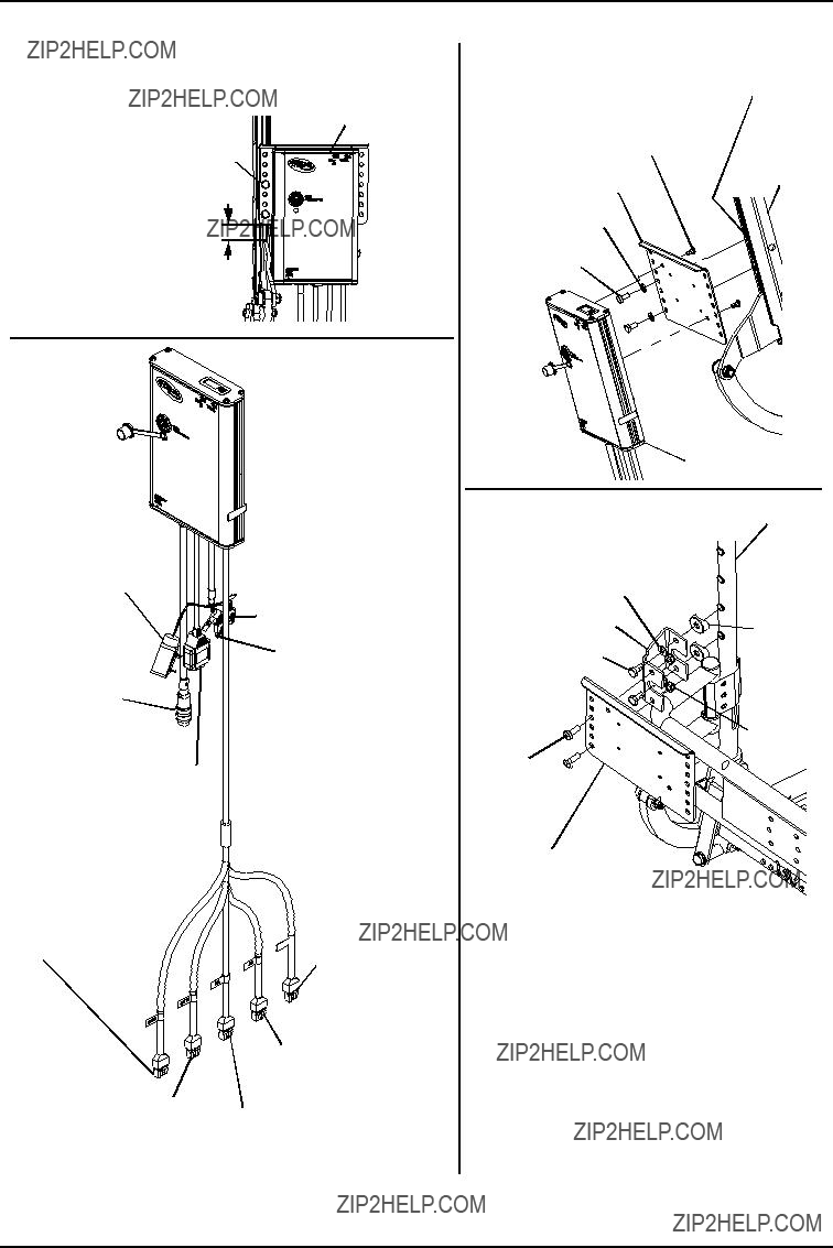


 TRCM/TAC
 Locknut


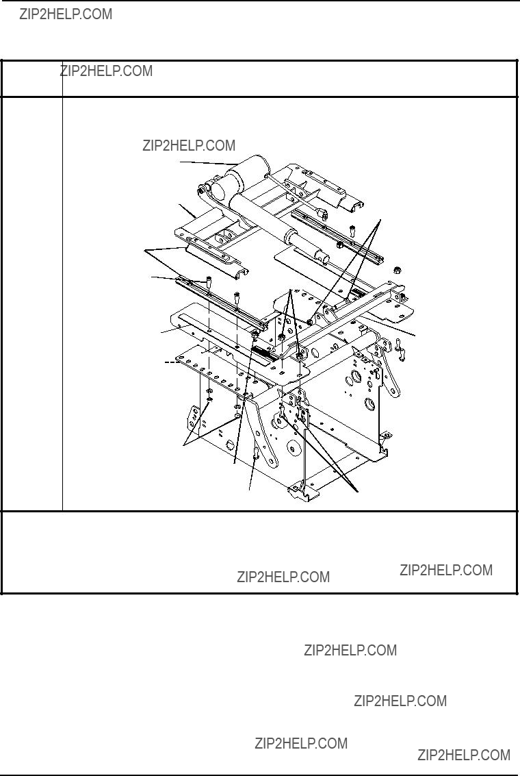
 Joystick
 Tie-Wrap


 Set Screw


 Set Screw


 Recline
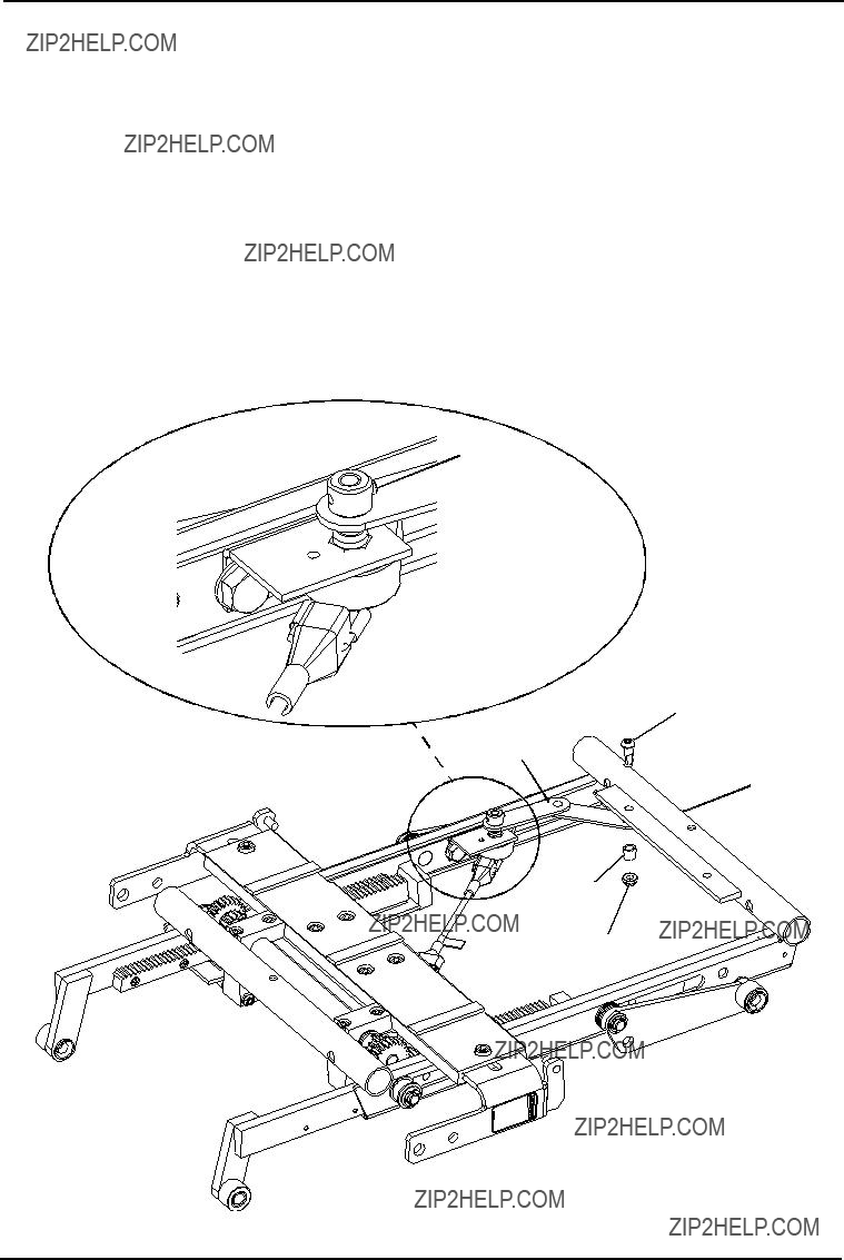
 Set Screw
 Nut
Nut
 Bracket
 Recline


 Tilt Potentiometer
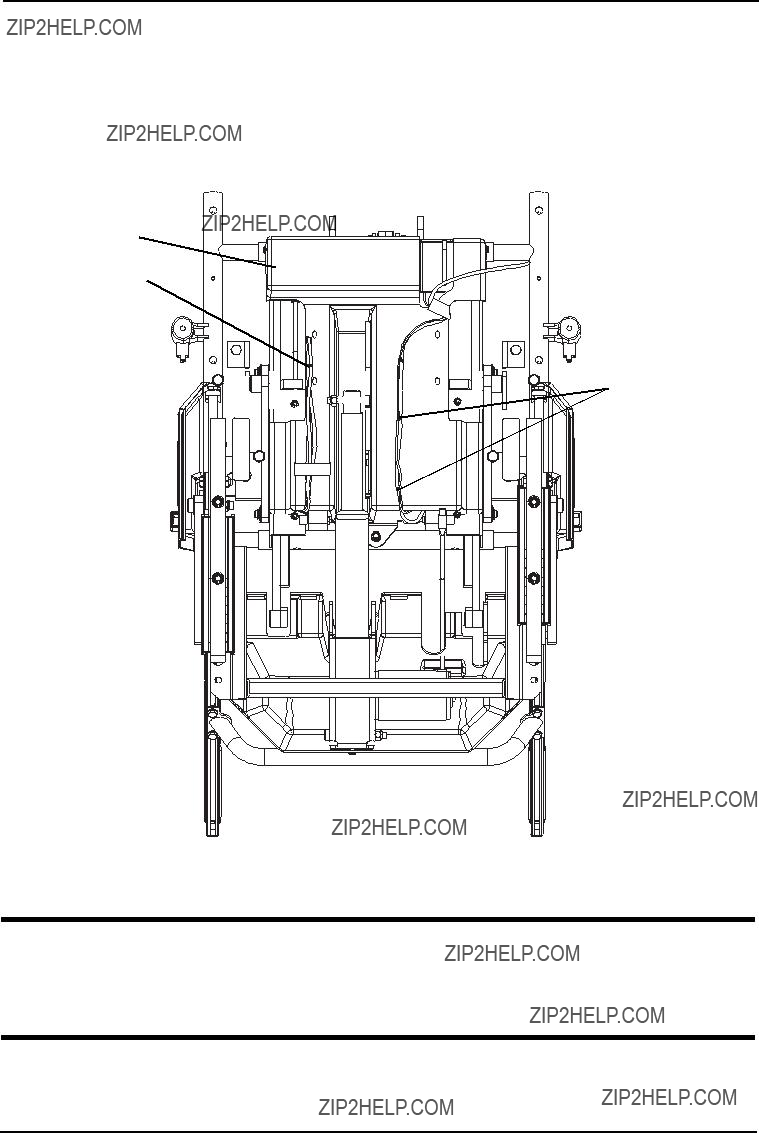


 Right
Right 


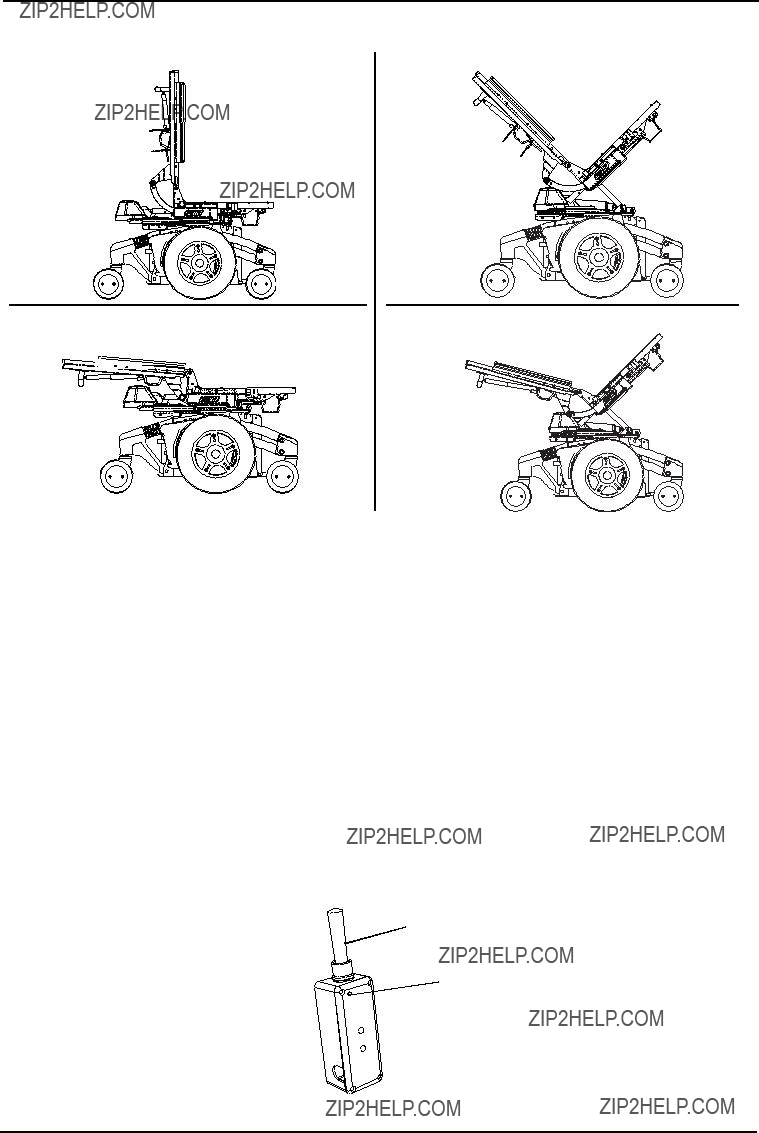
 TRCM Controller


 Tilt
Tilt
 Connector (Molex)
 (Custom

