LIMITED WARRANTY
LIMITED WARRANTY
PLEASE NOTE: THE WARRANTY BELOW HAS BEEN DRAFTED TO COMPLY WITH FEDERAL
LAW APPLICABLE TO PRODUCTS MANUFACTURED AFTER JULY 4, 1975. This warranty is extended only to the original purchaser/user of our products.
This warranty gives you specific legal rights and you may also have other legal rights which vary from state to state.
Invacare Continuing Care, Inc. (ICCI) warrants this product to be free from defects in materials and workmanship on the lift and the electric components for a period of one year from the date of purchase. If within such warranty period any such component shall be proven to be defective, such component shall be repaired or replaced, at ICCI???s option. This warranty does not include any labor or shipping charges incurred in replacement part installation or repair of any such product. ICCI???s sole obligation and your exclusive remedy under this warranty shall be limited to such repair and/or replacement.
For warranty service, please contact the dealer from whom you purchased your ICCI product. In the event you do not receive satisfactory warranty service, please write directly to ICCI at the address on the back cover, provide dealer???s name, address, date of purchase, indicate nature of the defect.
ICCI will issue a serialized return authorization. The defective unit or parts MUST be returned for warranty inspection using the serial number, when applicable as identification within 30 days of return authorization date. DO NOT return products to our factory without our prior consent. C.O.D. shipments will be refused; please prepay shipping charges.
LIMITATIONS AND EXCLUSIONS: THE FOREGOING WARRANTY SHALL NOT APPLY TO
SERIAL NUMBERED PRODUCTS IF THE SERIAL NUMBER HAS BEEN REMOVED OR DEFACED,
PRODUCTS SUBJECTED TO NEGLIGENCE, ACCIDENT, IMPROPER OPERATION,
MAINTENANCE OR STORAGE, PRODUCTS MODIFIED WITHOUT ICCI???S EXPRESS WRITTEN
CONSENT (INCLUDING, BUT NOT LIMITED TO, MODIFICATION THROUGH THE USE OF
UNAUTHORIZED PARTS OR ATTACHMENTS; PRODUCTS DAMAGED BY REASON OF
REPAIRS MADE TO ANY COMPONENT WITHOUT THE SPECIFIC CONSENT OF ICCI, OR TO
A PRODUCT DAMAGED BY CIRCUMSTANCES BEYOND ICCI???S CONTROL, AND SUCH
EVALUATION WILL BE SOLELY DETERMINED BY ICCI. THE WARRANTY SHALL NOT APPLY
TO PROBLEMS ARISING FROM NORMAL WEAR OR FAILURE TO ADHERE TO THE
INSTRUCTIONS IN THIS MANUAL.
THE FOREGOING WARRANTY IS EXCLUSIVE AND IN LIEU OF ANY OTHER EXPRESS
WARRANTIES. IMPLIED WARRANTIES, IF ANY, INCLUDING THE IMPLIED WARRANTIES OF
MERCHANTABILITY AND FITNESS FOR A PARTICULAR PURPOSE, SHALL NOT EXTEND
BEYOND THE DURATION OF THE EXPRESSED WARRANTY PROVIDED HEREIN AND THE
REMEDY FOR VIOLATIONS OF ANY IMPLIED WARRANTY SHALL BE LIMITED TO REPAIR OR
REPLACEMENT OF THE DEFECTIVE PRODUCT PURSUANT TO THE TERMS CONTAINED
HEREIN. ICCI SHALL NOT BE LIABLE FOR ANY CONSEQUENTIAL OR INCIDENTAL
DAMAGES WHATSOEVER.
SOME STATES DO NOT ALLOW EXCLUSION OR LIMITATION OF INCIDENTAL OR
CONSEQUENTIAL DAMAGE, OR LIMITATION ON HOW LONG AN IMPLIED WARRANTY
LASTS, SO THE ABOVE EXCLUSIONS AND LIMITATIONS MAY NOT APPLY TO YOU.
THIS WARRANTY SHALL BE EXTENDED TO COMPLY WITH STATE OR PROVINCIAL LAWS
AND REQUIREMENTS.


 Stretcher
 Button

 Lift
Lift
 Seat
Seat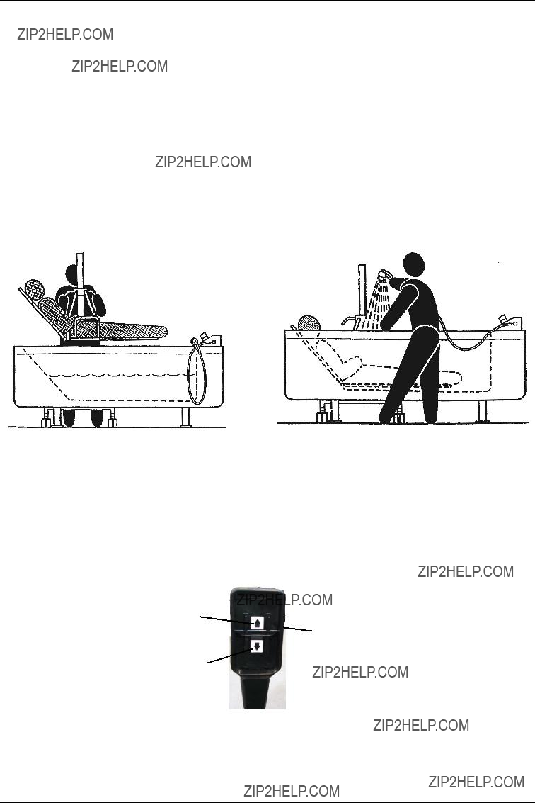


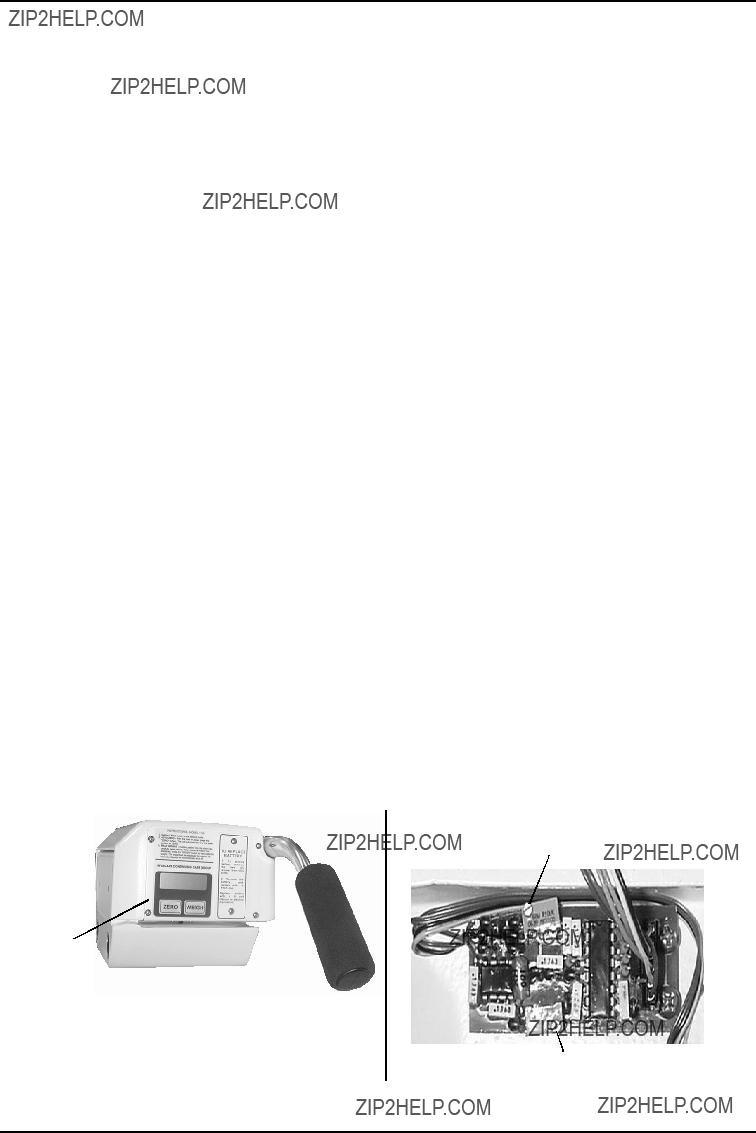
 Scale
Scale

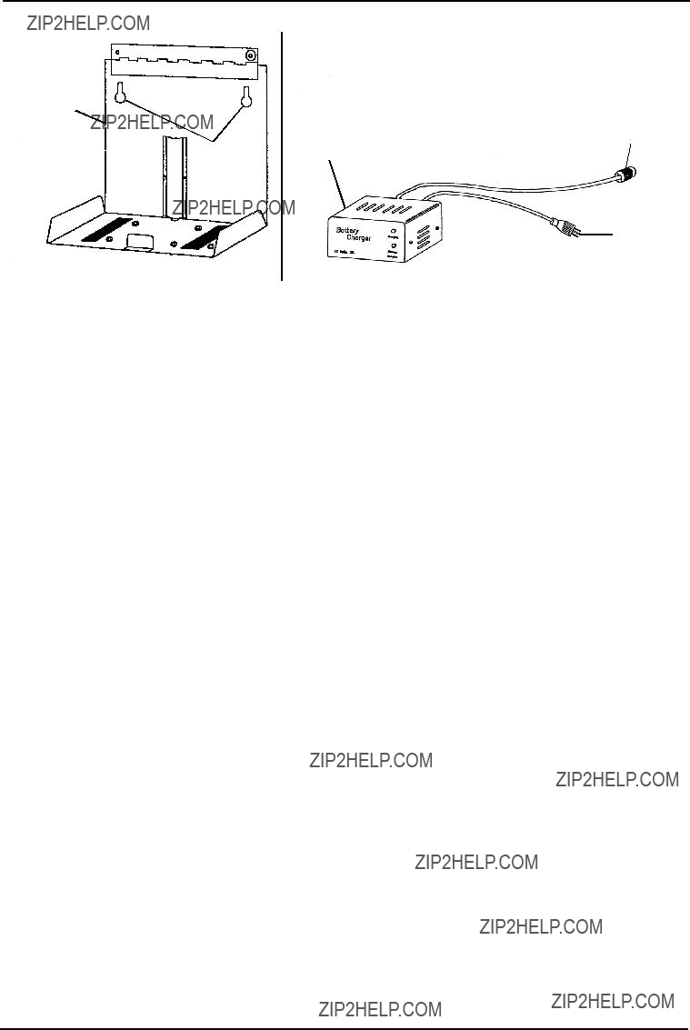
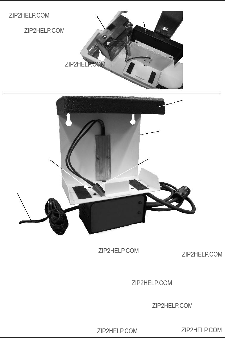

 Battery
 Charger


 Hanger rods

 Bolts
Bolts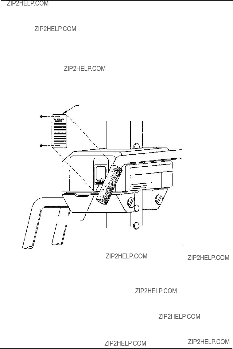
 (1 of 4)


 Outer Column
 Nylon
Nylon Lift Base
 Inner Column


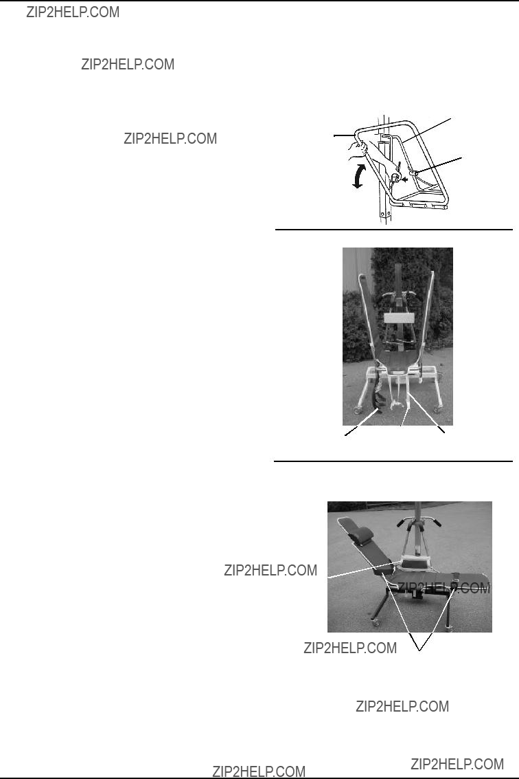


 Wing Arm
 Seat Strap
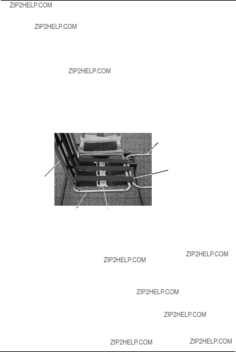
 Head End of the
 Buckle
 Back Strap
 Button

 White Strap