Owner???s Operator and Maintenance Manual
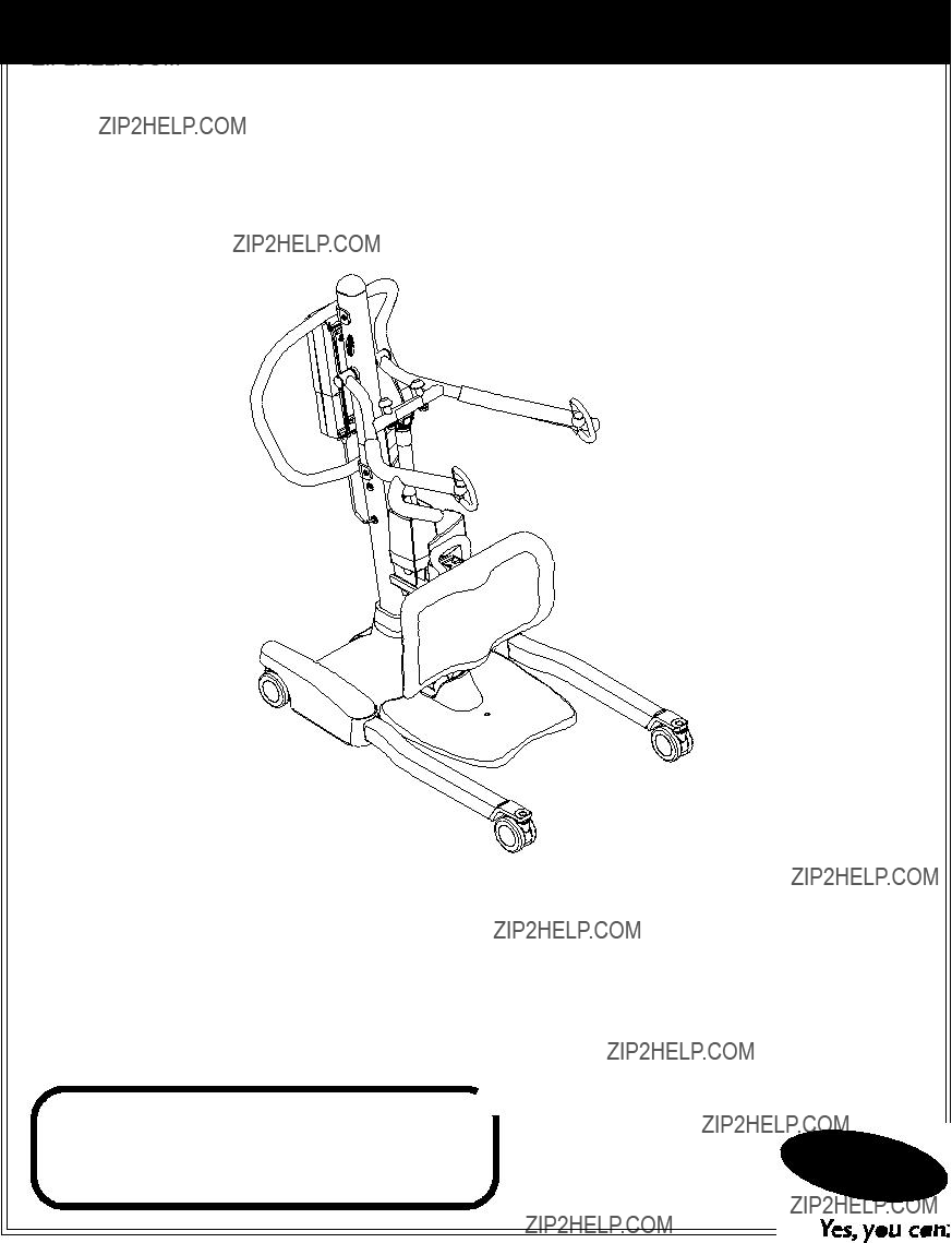
Roze??? Stand Up
Patient Lift
DEALER: This manual MUST be given to the user of this product.
USER: BEFORE using this product, read this manual and save for future reference.
For more information regarding Invacare products, parts, and services, please visit www.invacare.com
� WARNING
DO NOT OPERATE THIS EQUIPMENT WITHOUT FIRST READING AND
UNDERSTANDING THIS MANUAL. IF YOU ARE UNABLE TO UNDERSTAND
THE WARNINGS, CAUTIONS AND INSTRUCTIONS CONTACT A
QUALIFIED DEALER OR INVACARE TECHNICAL SUPPORT BEFORE
ATTEMPTING TO USE THIS EQUIPMENT - OTHERWISE INJURY OR
DAMAGE MAY RESULT.
� ACCESSORIES WARNING
Invacare products are specifically designed and manufactured for use in conjunction with Invac- are accessories. Accessories designed by other manufacturers have not been tested by Invacare and are not recommended for use with Invacare products.
SYMBOL LEGEND
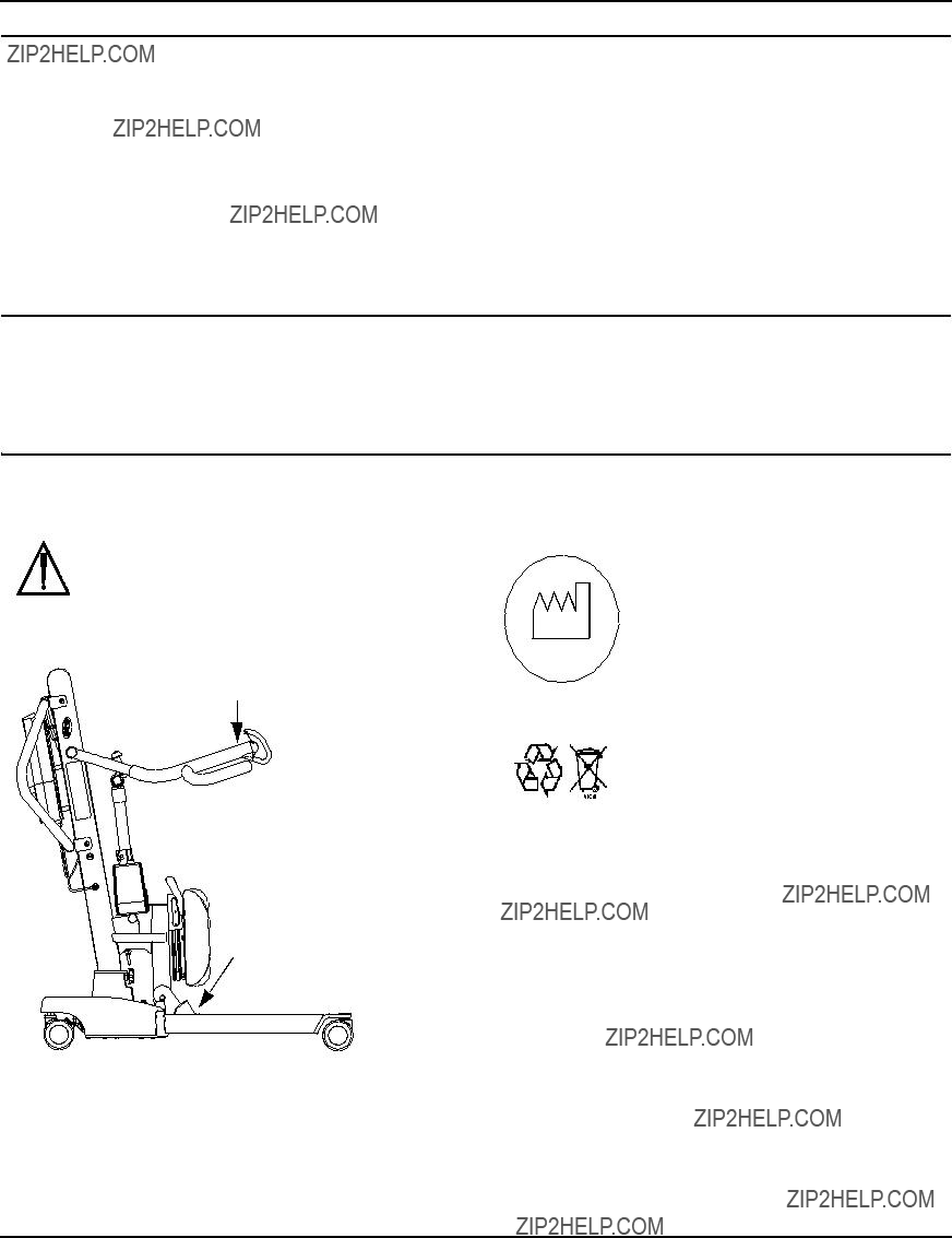
 "ATTENTION, see instructions for use".
WARNING - ALWAYS be aware of the Lift Arms. Injury to the patient and/or assistant may occur.
WARNING - ALWAYS be aware of the Footrest, especially the patient???s position on the footrest. Injury to the patient and/or assistant may occur.
SPECIAL NOTES
SPECIAL NOTES
Signal words are used in this manual and apply to hazards or unsafe practices which could result in personal injury or property damage. Refer to the table below for definitions of the signal words.
THE INFORMATION CONTAINED IN THIS DOCUMENT IS SUBJECT TO CHANGE
WITHOUT NOTICE.
RADIO FREQUENCY INTERFERENCE
Most electronic equipment is influenced by Radio Frequency Interference (RFI). CAUTION should be exercised with regard to the use of portable communication equipment in the area around such equipment. If RFI causes erratic behavior, PUSH the RED Emergency Stop Button IMMEDIATELY. DO NOT turn the Red Emergency Stop Button OFF while transmission is in progress.
MAINTENANCE
Maintenance MUST be performed ONLY by qualified personnel.
LABEL LOCATION
NOTE: Sling Size label is located on cross bar (not shown).
 WARNING
USE ONLY INVACARE
SLINGS and LIFT
ACCESSORIES.
PRODUCT PARAMETERS
*NOTE: Varies depending upon load and stroke.
SECTION 1???GENERAL GUIDELINES
SECTION 1???GENERAL GUIDELINES
� WARNING
SECTION 1 - GENERAL GUIDELINES contains important information for the safe operation and use of this product.
Check all parts for shipping damage before using. In case of damage, DO NOT use the equipment. Contact the Dealer for further instructions.
The Invacare patient lift is NOT a transport device. It is intended to transfer an individual from one seated surface to another (such as a bed to a wheelchair).
DO NOT attempt any transfer without approval of the patient???s physician, nurse or medical assistant. Thoroughly read the instructions in this Owner???s Manual, observe a trained team of experts perform the lifting procedures and then perform the entire lift procedure several times with proper supervision and a capable individual acting as a patient.
Invacare Stand Assist and Transfer slings are specifically designed to be used in conjunction with Invacare patient lifts. Slings and accessories designed by other manufacturers are not to be utilized as a component of Invacare???s patient lift system. Use of these products is prohibited and will void the lift???s warranty. Use the sling that is recommended by the individual???s doctor, nurse or medical assistant for the comfort and safety of the individual that is being lifted.
If the patient lift is used in the area of a shower or bath, ensure that the patient lift is wiped clean of any moisture after use. DO NOT store the lift in a damp area or in a damp condition. Periodically inspect all components of the patient lift for signs of corrosion. Replace all parts that are corroded or damaged.
Weight Limitation
DO NOT exceed maximum weight limitation of the patient lift. The weight limitation for the Roze Patient Lift is 450 lbs.
Assembling the Lift
DO NOT overtighten mounting hardware. This will damage mounting brackets.
Using the Sling
Individuals that use the Stand Assist Sling MUST be able to support the majority of their own weight, otherwise injury may occur.
Stand Assist Slings: DO NOT use the stand assist sling in combination with the patient lift as a transport device. It is intended to transfer an individual from one resting surface to another (such as a bed to a wheelchair).
Stand Assist Slings: Before lifting the patient, make sure the bottom edge of the stand assist sling is positioned on the lower back of the patient and the patient???s arms are outside the stand assist sling.
Stand Assist Slings: The belt MUST be snug, but comfortable on the patient, otherwise the patient can slide out of the sling during transfer, possibly causing injury.
Transfer Slings: Before lifting the patient, make sure the bottom edge of the transfer sling is at the base of the spine and the patient???s arms are outside the transfer sling.
Transfer Slings: DO NOT raise the patient to a full standing position while using the transfer sling, otherwise injury may occur.
After each laundering (in accordance with instructions on the sling), inspect sling(s) for wear, tears, and loose stitching. Bleached, torn, cut, frayed, or broken slings are unsafe and could result in injury. Discard immediately.
DO NOT alter slings.
Be sure to check the sling attachments each time the sling is removed and replaced, to ensure that it is properly attached before the patient is removed from a stationary object (bed, chair or commode).
If the patient is in a wheelchair, secure the wheel locks in place to prevent the chair from moving forwards or backwards.
Operating the Lift
Make sure there is an audible click when mounting battery on the battery charger to confirm proper mounting. Otherwise, injury or damage may occur.
Use the handles to push or pull the patient lift.

SECTION 1???GENERAL GUIDELINES
Lifting the Patient
Before positioning the legs of the stand up lift around the patient, make sure that the patient???s feet are out of the way of the foot plate, otherwise injury may occur.
Adjustments for safety and comfort should be made before moving the patient. Patient's arms should be outside of the sling straps.
Before lifting a patient from a stationary object (wheelchair, commode or bed), slightly raise the patient off the stationary object and check that all sling attachments are secure. If any attachment is not correct, lower the patient and correct the problem, then raise the patient and check again.
During transfer, with the patient suspended in a sling attached to the lift, DO NOT roll caster base over uneven surfaces that would create an imbalance of the patient lift and could cause the patient lift to tip over. Use steering handle on the mast at ALL times to push or pull the patient lift.
Invacare recommends locking the rear swivel casters ONLY when positioning or removing the sling (stand assist or transfer) from around the patient.
Invacare does NOT recommend locking of the rear casters of the patient lift when lifting an individual. Doing so could cause the lift to tip and endanger the patient and assistants. Invacare DOES recommend that the rear casters be left unlocked during lifting procedures to allow the patient lift to stabilize itself when the patient is initially lifted from a chair, bed or any stationary object.
Transferring the Patient
Before transferring, check that the product???s weight capacity can withstand the patient's weight.
Wheelchair wheel locks MUST be in a locked position before lowering the patient into the wheelchair for transport.
Performing Maintenance
Regular maintenance of patient lifts and accessories is necessary to assure proper operation.
After the first 12 months of operation, inspect all pivot points and fasteners for wear. If the metal is worn, the parts MUST be replaced. Perform this inspection every six months thereafter.
DO NOT overtighten mounting hardware. This will damage mounting brackets.
Casters and axle bolts require inspections every six months to check for tightness and wear.
SECTION 2???ASSEMBLY
Attaching the Battery Charger Mounting Bracket to the Wall
NOTE: For this procedure, refer to FIGURE 2.4.
1.Place the battery charger mounting bracket on the wall at the desired position.
2.With a pencil, mark the middle hole position.
3.Measure down 6?? inches from the pencil mark and drill one mounting hole.
4.Install the bottom mounting screw until there is an approximate 1/8-inch gap between the screw head and the wall.
5.Put the battery charger mounting bracket onto the bottom mounting screw.
6.Drill the other two mounting holes.
� CAUTION
Make sure there is an audible click when mounting battery on the battery charger to confirm proper mounting. Otherwise, injury or damage may occur.
9.Plug the battery charger into an electrical outlet.
NOTE: An LED will illuminate when power is applied to battery charger.
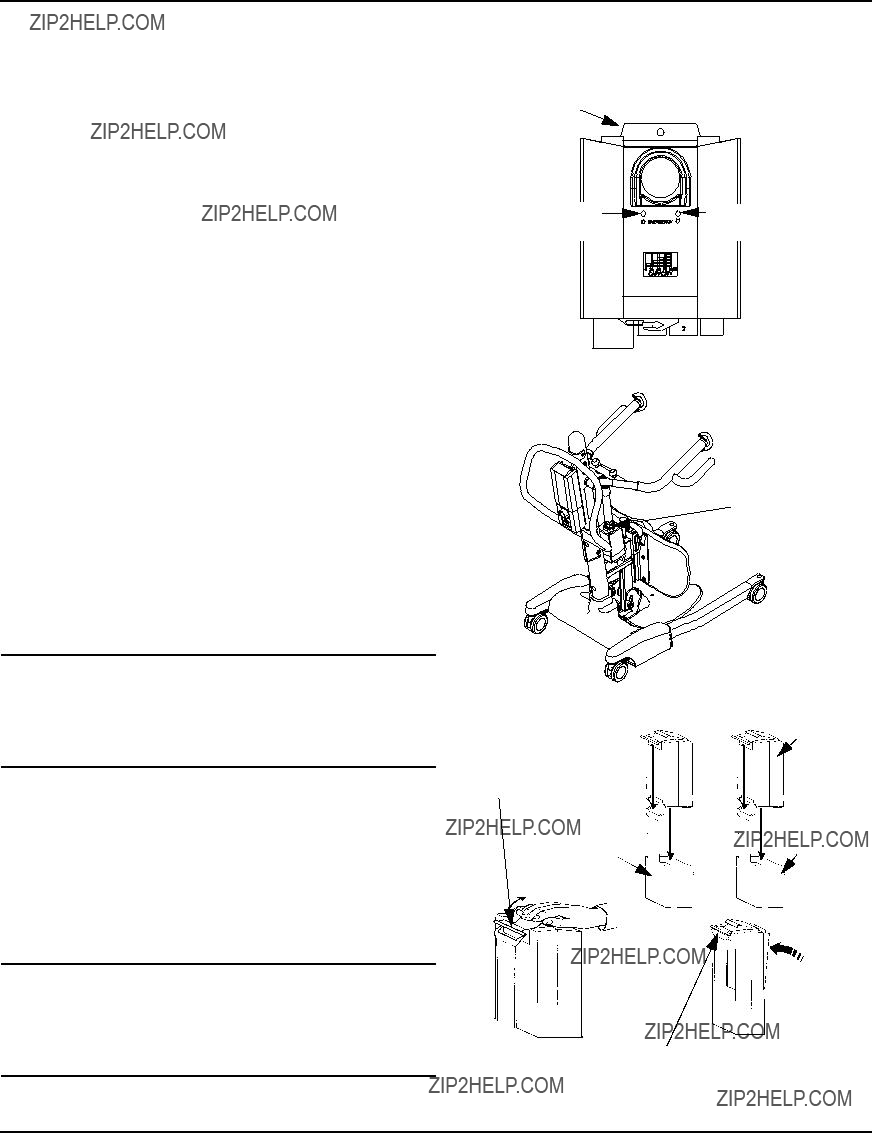
FIGURE 2.4 Attaching the Battery Charger Mounting Bracket
Attaching the Battery Charger to the Mastto the Wall
Assembly
� WARNING
If the battery charger is attached to the mast assembly and is plugged into a wall outlet, make sure to unplug the battery charger from the wall outlet BEFORE using the patient lift. Failure to unplug the battery charger may result in injury or damage.
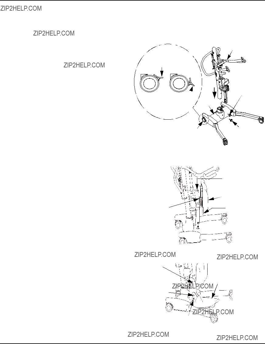
NOTE: For this procedure, refer to FIGURE 2.5.
1.Remove the two mylar pieces covering the mounting holes on the back of the mast assembly.
2.Insert the hook screws into mounting holes.
3.Tighten the hook screws.
4.Mount the battery charger mounting bracket on the hook screws.
5.Charge the battery. Refer to Primary Emergency Release on page 13.
Battery and Battery Charger shown in place on mast assembly
FIGURE 2.5 Attaching the Battery Charger to the Mast Assembly
SECTION 3??? OPERATION
� WARNING
DO NOT attempt to transfer a patient without approval of the patient???s physician, nurse, or medical assistant. Thoroughly read the instructions in this owner???s manual, observe a trained team of experts performing the lifting procedures and then perform the entire lift procedure several times with proper supervision and a capable individual acting as a patient.
The legs of the stand up lift MUST be in the maximum open position for optimum stability and safety. If the patient is in a sling and it becomes necessary to move through a narrow passage, close the legs of the stand up lift only as long as it takes to move through the passage. When the stand up lift is through the passage, return the legs to the maximum open position.
NOTE: The use of the patient lift by one assistant should be based on the evaluation of the health care professional for each individual case.
Operating the Patient Lift
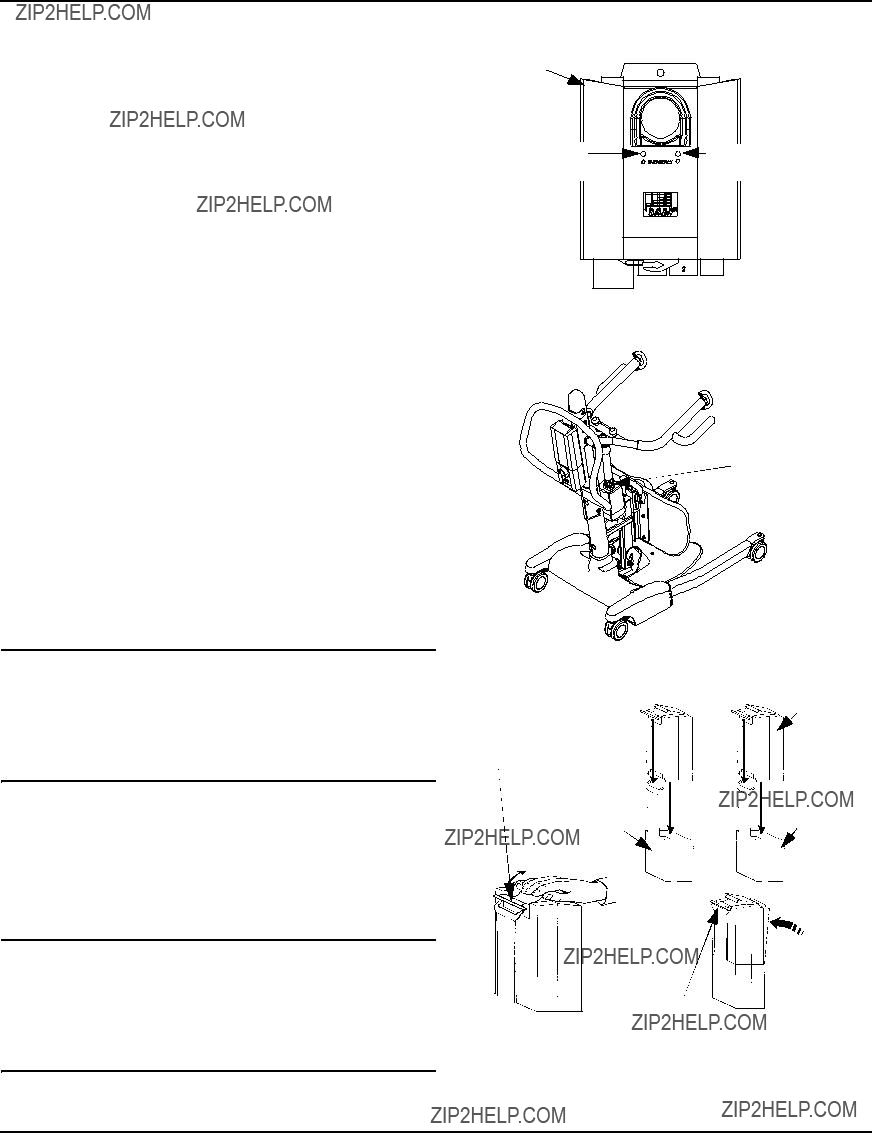
NOTE: For this procedure, refer to FIGURE 3.1.
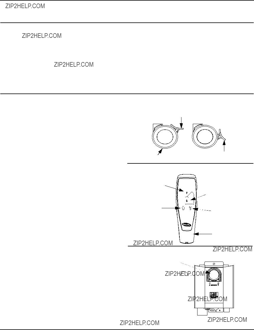
Locking/Unlocking the Rear Casters
NOTE: For this procedure, refer to Detail ???A???.
???To Lock the Caster: Push tab down.
???To Unlock the Caster: Push tab up.
DETAIL ???A???
LOCKING/UNLOCKING THE REAR CASTERS
Push tab DOWN to LOCK
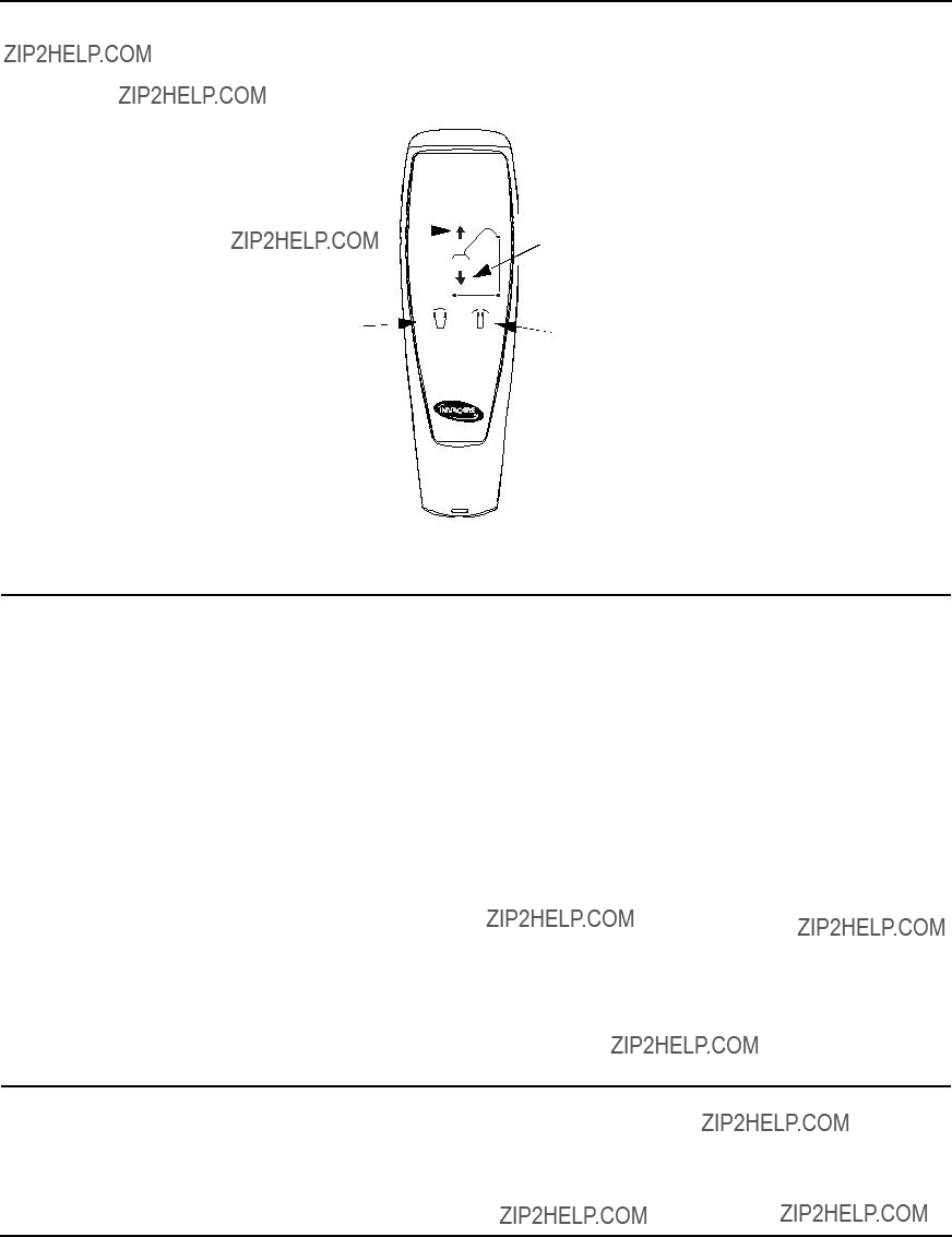
DETAIL ???B??? - HAND CONTROL DETAILS
Raising/Lowering the Patient Lift
NOTE: For this procedure, refer to Detail ???B???.
???To Raise the Patient Lift:
Press the up (???) button on the hand control.
NOTE: If the patient lift is raised to the highest level, it may be necessary to pull down gently on the lift arms before the mast will begin to lower. Pull down gently on both arms at the same time to avoid making the lift unstable.
???To Lower the Patient Lift:
Press the down button (???) on the hand control.
Closing/Opening the Legs
NOTE: For this procedure, refer to Detail ???B???.
???To Close the Legs:
Press the close button on the hand control.
???To Open the Legs:
Press the open button on the hand control.
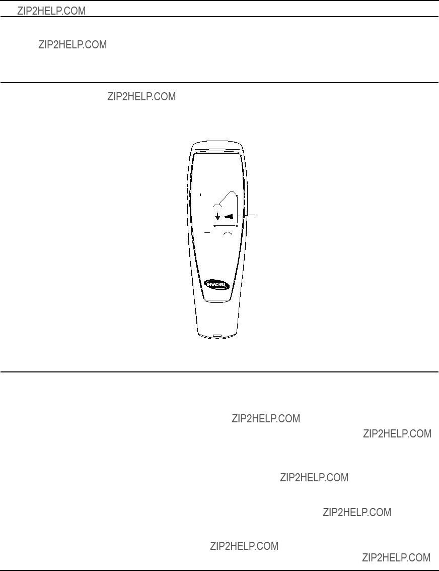
Using the Emergency Stop
NOTE: For this procedure, refer to Detail ???C???.
???Push the RED emergency button in to stop the lift arms from raising or lowering.
???To reset, rotate the emergency button clockwise.
DETAIL ???C??? - EMERGENCY STOP
Emergency Button
Push in to stop, turn clockwise to reset.
FIGURE 3.1 Operating the Patient Lift
SECTION 4???LIFTING THE PATIENT
SECTION 4???LIFTING THE PATIENT
� WARNING
DO NOT exceed the maximum weight limitation of 450 lbs.
DO NOT attempt to any transfer without approval of the patient???s physician, nurse or medical assistant.
ALWAYS keep hands and fingers clear of moving parts to avoid injury.
Invacare patient slings are made specifically for use with Invacare patient lifts. For the safety of the patient, DO NOT intermix patient slings and patient lifts of different manufacturers.
Individuals that use the standing patient sling MUST be able to support the majority of their own weight, otherwise injury may occur.
Before lifting the patient, make sure the bottom edge of the standing patient sling is positioned on the lower back of the patient and the patient???s arms are outside the standing patient sling. The belt MUST be snug, but comfortable on the patient, otherwise the patient can slide out of the patient sling during transfer possibly causing injury.
After EACH laundering (in accordance with laundering instructions on the patient sling), inspect the patient sling for wear, tears and loose stitching. Discard any patient sling that meets these criteria
IMMEDIATELY.
Bleached, torn, cut, frayed or broken slings are unsafe and their use could result in injury or damage. Discard any patient sling that meets these criteria IMMEDIATELY.
DO NOT alter patient slings.
DO NOT move the patient if the patient sling is not properly connected to the attachment points on the patient lift. Check that the patient sling is properly connected to the attachment points BEFORE lifting the patient.
During transfer, with the patient suspended in the patient sling, DO NOT roll the base of the patient lift over any uneven surfaces that would cause the patient lift to become unstable.
Use the steering handle on the mast assembly at all times to push or pull the stand up lift.
NOTE: Refer to the patient sling Owner???s Manual, P/N 102891, for more information.
Positioning the Stand Up Lift
NOTE: For this procedure, refer to FIGURE 4.1 on page 15.
NOTE: Refer to General Guidelines on page 8 before proceeding and observe all warnings indicated.
NOTE: Before positioning the legs of the patient lift under a bed, make sure that the area is clear of any obstructions.
� WARNING
The legs of the stand up lift MUST be in the maximum open position for optimum stability and safety. If it is necessary to close the legs to maneuver the stand up lift under a bed, close the legs only as long as it takes to position the stand up lift over the patient and lift the patient off the surface of the bed. When the legs of the stand up lift are no longer under the bed, return the legs to the maximum open position.
1.Press the legs open button on the hand control to open the legs of the stand up lift to the maximum open position.
SECTION 4???LIFTING THE PATIENT
2.Position the stand up lift using the mast handle.
3.Press the down arrow button on the hand control to lower the lift arms for easy attachment to the sling.
4.Lower the patient lift for easy attachment of the patient sling.
 Hand Control
FIGURE 4.1 Hand Control Buttons
Lifting the Patient
� WARNING
DO NOT exceed the maximum weight limitation of 450 lbs.
Individuals that use the standing patient sling MUST be able to support the majority of their own weight, otherwise injury may occur.
DO NOT lock the rear casters of the stand up lift when lifting an individual. Locking the rear casters could cause the stand up lift to tip and endanger the patient and assistants. Unlocking the rear casters during lifting procedures allows the lift to stabilize itself while the patient is initially lifted from a wheelchair, bed of any stationary object.
DO NOT move the patient if the sling is not properly attached to the attachment points on the stand up lift. Make sure that the sling is properly attached BEFORE lifting the patient. If any attachments are not properly in place, correct the problem. When the sling is elevated a few inches off the stationary surface and before moving the patient, check again to make sure the sling and all attachments are securely in place. If any problem is found, lower the patient back onto the stationary surface and correct the problem - otherwise, injury or damage may occur.
Adjustments for safety and comfort should be made before moving the patient.
Invacare patient slings are made specifically for use with Invacare patient lifts. For the safety of the patient, DO NOT intermix patient slings and patient lifts of different manufacturers.
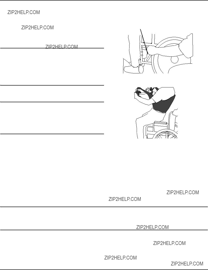
NOTE: For this procedure, refer to FIGURE 4.2 on page 16.
NOTE: The patient MUST be in a seated position first. Use the head section of the bed to get the patient upright then move legs over the side of the bed.
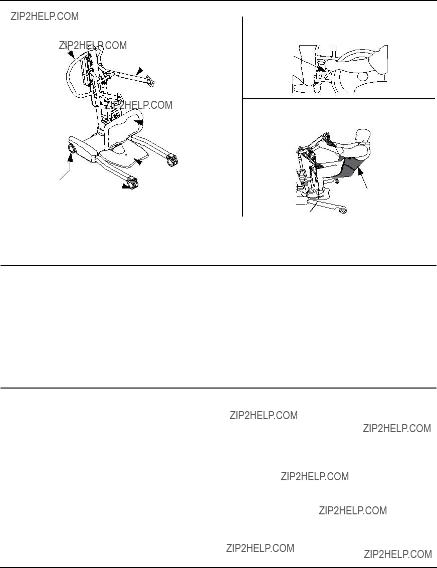
1.Instruct the patient to hold onto the hand grips on both sides of the stand up lift (Detail ???A??? of FIGURE 4.2).
2.Instruct the patient to lean back into the standing or transfer sling.
SECTION 4???LIFTING THE PATIENT
� WARNING
Standing Slings - Before lifting the patient, make sure the bottom edge of the standing sling is positioned on the lower back of the patient and the patient???s arms are outside the sling.
Transfer Slings - Before lifting the patient, make sure the bottom edge of the transfer sling is at the base of the spine and the patient???s arms are outside the sling.
3.Ensure the following:
A.The patient???s knees are secure against the knee pad.
B.The patient???s feet are properly positioned on the foot plate.
C.Slings:
???Standing Sling - the bottom edge of the standing sling is positioned on the patient???s lower back.
???Transfer Sling - the bottom edge of the transfer sling is at the base of the patient???s spine.
???Either Sling Style - the patient???s arms are outside the sling.
D.The rear casters are unlocked.
E.The legs are in the maximum open position.
� WARNING
If transferring a patient from a wheelchair, the wheelchair wheel locks MUST be in the locked posi- tion before lowering the patient into the wheelchair. Otherwise, injury may occur.
4.If transferring from a wheelchair, lock the wheel locks on the wheelchair (Detail ???B??? of FIGURE 4.2).
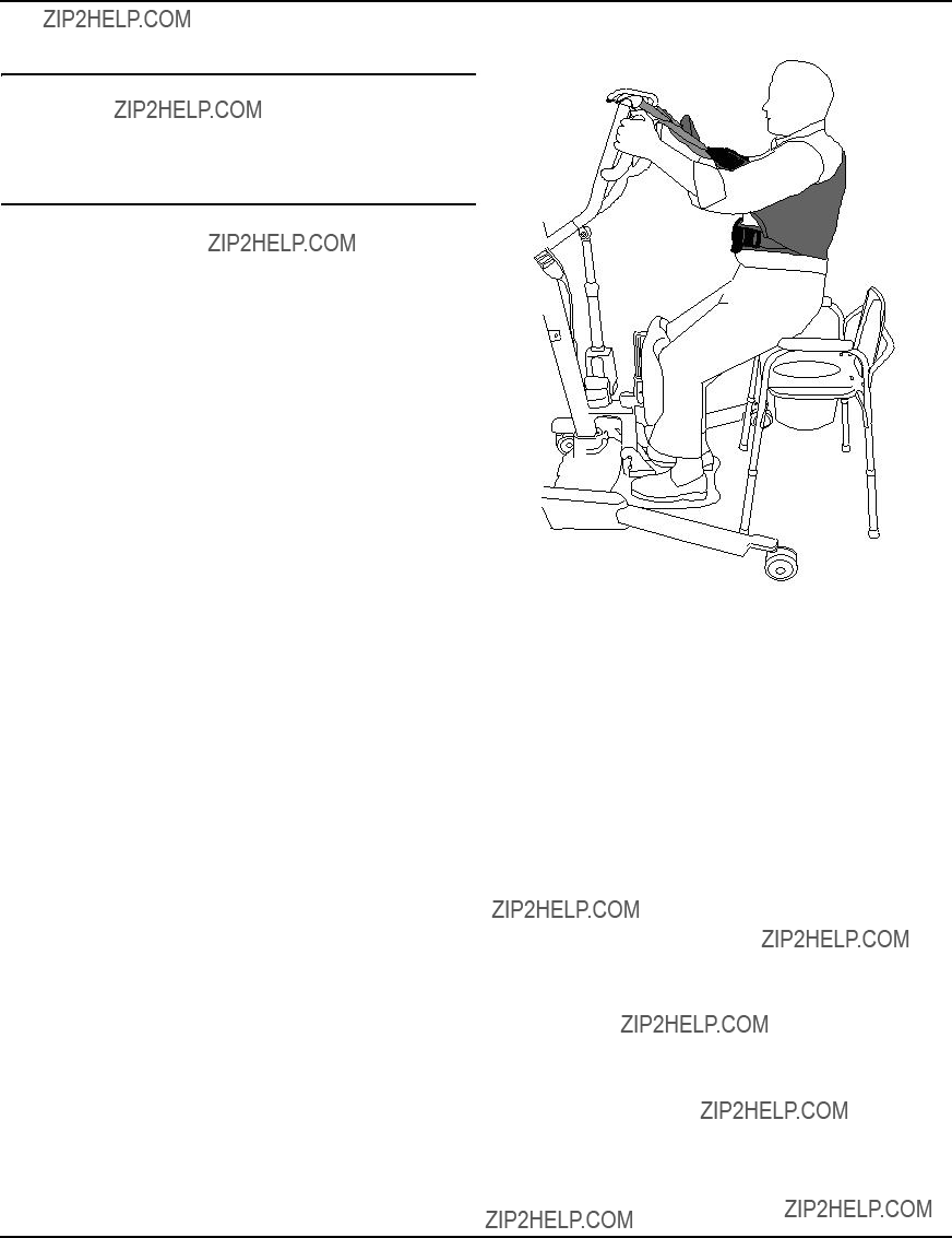
5.Press the UP arrow button on the hand control to raise the patient above the surface (bed, wheelchair or commode). The patient???s weight will be fully supported by the stand up lift (Detail ???C??? of FIGURE 4.2).
NOTE: The lower center of gravity provides stability making the patient feel more secure and the lift easier to move.
DETAIL ???C??? - LIFTING THE PATIENT
Knee Pad
FIGURE 4.2 Lifting the Patient
SECTION 4???LIFTING THE PATIENT
Moving the Patient
� WARNING
The legs of the stand up lift MUST be in the maximum open position for optimum stability and safety. If the patient is in a sling and it becomes necessary to move through a narrow passage, close the legs of the stand up lift only as long as it takes to move through the passage. When the stand up lift is through the passage, return the legs to the maximum open position.
DO NOT, during transfer of a patient suspended in the lift sling, roll caster base over uneven sur- faces that would create an imbalance of the lift. This could cause the lift to tip over. Use the mast handle at all times to push or pull the lift.
1.Ensure the legs of the stand up lift are in the maximum open position. If not, press the OPEN LEGS button on the hand control to move the legs to the maximum open position.
2.Move the stand up lift away from the surface they were lifted from.
3.Slowly move the patient to the desired surface.
SECTION 5???TRANSFERRING THE PATIENT
SECTION 5???TRANSFERRING THE PATIENT
� WARNING
DO NOT attempt any transfer of a patient without the approval of the patient???s physician, nurse or medical assistant.
DO NOT move the patient if the sling is not properly connected to the attachment points of the stand up lift. Check that the sling is properly connected to the attachment points prior to lifting a patient. If any attachments are not properly in place, correct the problem. When the sling is elevated a few inches off the stationary surface and before moving the patient, check again to make sure that all sling attachments are secure. If any attachments are not properly in place, lower the patient back onto the stationary surface and correct this problem - otherwise, injury or damage may occur.
Adjustments for safety and comfort should be made before moving the patient. The patient's arms should be outside the straps.
DO NOT use slings and stand up lifts of different manufacturers. Invacare slings are made specifically for use with Invacare stand up lifts. Otherwise, injury or damage may occur.
DO NOT lock the rear casters of the stand up lift when lifting an individual. Locking the rear casters could cause the stand up lift to tip and endanger the patient and assistants.
The legs of the stand up lift MUST be in the maximum open position for optimum stability and safety. If the patient is in a sling and it becomes necessary to move through a narrow passage, close the legs of the stand up lift only as long as it takes to move through the passage. When the stand up lift is through the passage, return the legs to the maximum open position. If it is necessary to close the legs to maneuver the stand up lift under a bed, close the legs only as long as it takes to position the stand up lift over the patient and lift the patient off the surface of the bed. When the legs of the stand up lift are no longer under the bed, return the legs to the maximum open position.
Be sure to check the sling attachments each time the sling is removed and replaced to ensure that it is properly attached before the patient is removed from a surface.
The use of one assistant is based on the evaluation of the health care professional for each individual case.
SECTION 5???TRANSFERRING THE PATIENT
Transferring to a Commode
� WARNING
Invacare recommends locking the rear swivel casters only when positioning or removing the sling from around the patient.
NOTE: For this procedure, refer to FIGURE 5.1.
1. Lift the patient from the side of the bed.
2. Press the UP button on the hand control to elevate the patient high enough to clear the arms of the commode chair. Their weight will be supported by the stand up lift.
3. Guide the patient onto the commode chair. This may require two assistants.
4. Press the down arrow button to lower the patient onto the commode chair.
5. Lock the rear swivel casters on the stand up lift.
6. Perform one of the following:
??? Standing Sling - unhook the standing sling from the attachment points on the stand up lift.
??? Transport Sling -
iii.If desired, unhook the transport sling from the top attachment points on the stand up lift.
NOTE: The patient can remain in the upper portion of the transfer sling while using the commode.
7.Instruct or assist the patient in lifting their feet off the foot plate.
8.Remove the sling from around the patient.
9.Unlock the rear casters and pull the stand up lift away from the commode.
10.When complete, recheck the sling for correct attachments.
11.To lift the patient from the commode.
SECTION 5???TRANSFERRING THE PATIENT
Transferring to a Wheelchair
NOTE: For this procedure, refer to FIGURE 5.2.
1.Ensure the legs of the lift with the patient in the sling are in the open position. Press the legs open button until in maximum open position.
2.Move the wheelchair into position.
3.Engage the wheel locks of the wheelchair to prevent movement of the chair (Detail ???A???).
� WARNING
DO NOT place the patient in the wheelchair if the locks are not engaged. The wheelchair wheel locks MUST be in a locked position before lowering the patient into the wheelchair for transport. Other- wise, injury may result.
4.Position the patient over the wheelchair (Detail ???B???).
5.Press the down arrow button and lower the patient into the wheelchair.
� WARNING
Lock the rear swivel casters ONLY when position- ing or removing the sling (standing or transfer) from around the patient. Otherwise, injury may occur.
6.Lock the rear swivel casters.
7.Unhook the sling from all attachment points on the lift.
8.Instruct patient to lift their feet off the foot plate. Assist the patient if necessary.
9.Remove the sling from around the patient.
10.Unlock the rear casters and pull the stand up lift away from the wheelchair.
Transferring to a Bed
DETAIL ???A???
Wheel
Lock
DETAIL ???B???
FIGURE 5.2 Transferring the Patient to a Wheelchair
NOTE: The lower center of gravity provides stability making the patient feel more secure and the lift easier to move.
1.Position the patient as far over the bed as possible.
NOTE: If patient is being transferred from a surface that is lower than the bed, press the up arrow button to raise the patient above the surface of the bed. The patient should be elevated just high enough to clear the bed with their weight fully supported by the lift.
2.Press the down arrow button and lower the patient onto the bed.
� WARNING
Invacare recommends locking the rear swivel casters ONLY when positioning or removing the sling from around the patient.
3.Lock the rear swivel casters.
4.Unhook the standing or transport sling from all attachment points on the stand up lift.
5.Instruct the patient to lift their feet off of the foot plate.
NOTE: Assist the patient if necessary.
6.Remove the standing or transport sling from around the patient.
7.Unlock the rear casters and pull the stand up lift away from the bed.
NOTE: If problems are not remedied by the suggested means, please contact your dealer or Invacare.
SECTION 7???MAINTENANCE
SECTION 7???MAINTENANCE
Maintenance Safety Inspection Checklist
NOTE: Follow the maintenance procedures described in this manual to keep your patient lift in continuous service.
The Invacare Patient Lift is designed to provide a maximum of safe, efficient and satisfactory service with minimum care and maintenance.
All parts of the Invacare Lift are made of the best grades of steel, but metal to metal contact will wear after considerable use.
There is no adjustment or maintenance of the casters, other than cleaning, lubrication and checking axle and swivel bolts for tightness. Remove all debris, etc. from the wheel and swivel bearings. If any parts are worn, replace these parts IMMEDIATELY.
If you question the safety of any part of the lift, contact your Dealer IMMEDIATELY.

SECTION 7???MAINTENANCE
Cleaning the Sling and the Lift
The sling should be washed regularly in water temperature not exceeding 180??F (82??C) and a biological solution. A soft cloth, dampened with water and a small amount of mild detergent, is all that is needed to clean the patient lift. The lift can be cleaned with non-abrasive cleaners.
Detecting Wear and Damage
It is important to inspect all stressed parts, such as slings, lifting arm and any pivot for slings for signs of cracking, fraying, deformation or deterioration. Replace any defective parts IMMEDIATELY and ensure that the lift is not used until repairs are made.
Lubricating the Lift
The Invacare lift is designed for minimum maintenance. However, a six month check and lubrication should ensure continued safety and reliability.
Keep lift and slings clean and in good working order. Any defect should be noted and reported to your dealer as soon as possible.
The casters MUST swivel and roll smoothly. A light grease (waterproof auto lubricant) may be applied to the ball bearing swivel of the casters once a year. Apply more frequently if the casters are exposed to extreme moist conditions.
Replacing the Electric Actuator
NOTE: For this procedure, refer to FIGURE 7.1 on page 24.
1.Unplug the electric actuator from the control box on the mast assembly. Thread the actuator lead through the actuator lead routing hole in the mast assembly.
2.Remove the hardware that secures the top of the electric actuator to the lift arm actuator mounting bracket.
A.Remove the rubber caps from the nut and screw that attach the electric actuator to the lift arm actuator mounting bracket.
B.Remove the screw, washer, bearing, nylon washer, actuator cap, bushing, nylon washer, bearing, washer, flat washer and nut.
NOTE: The actuator cap will become loose when the attaching hardware is removed. Inspect the actuator cap for damage. Replace the actuator cap if damage is found.
3.Remove the hardware that secures the bottom of the electric actuator to the mast assembly actuator mounting bracket.
A.Remove the rubber caps from the nut and screw that attach the electric actuator to the mast assembly actuator mounting bracket.
B.Remove the screw, washer, bearing, nylon washer, bushing, nylon washer, bearing, washer, flat washer, and nut.
4.To replace the electric actuator, reverse STEPS 1-3.
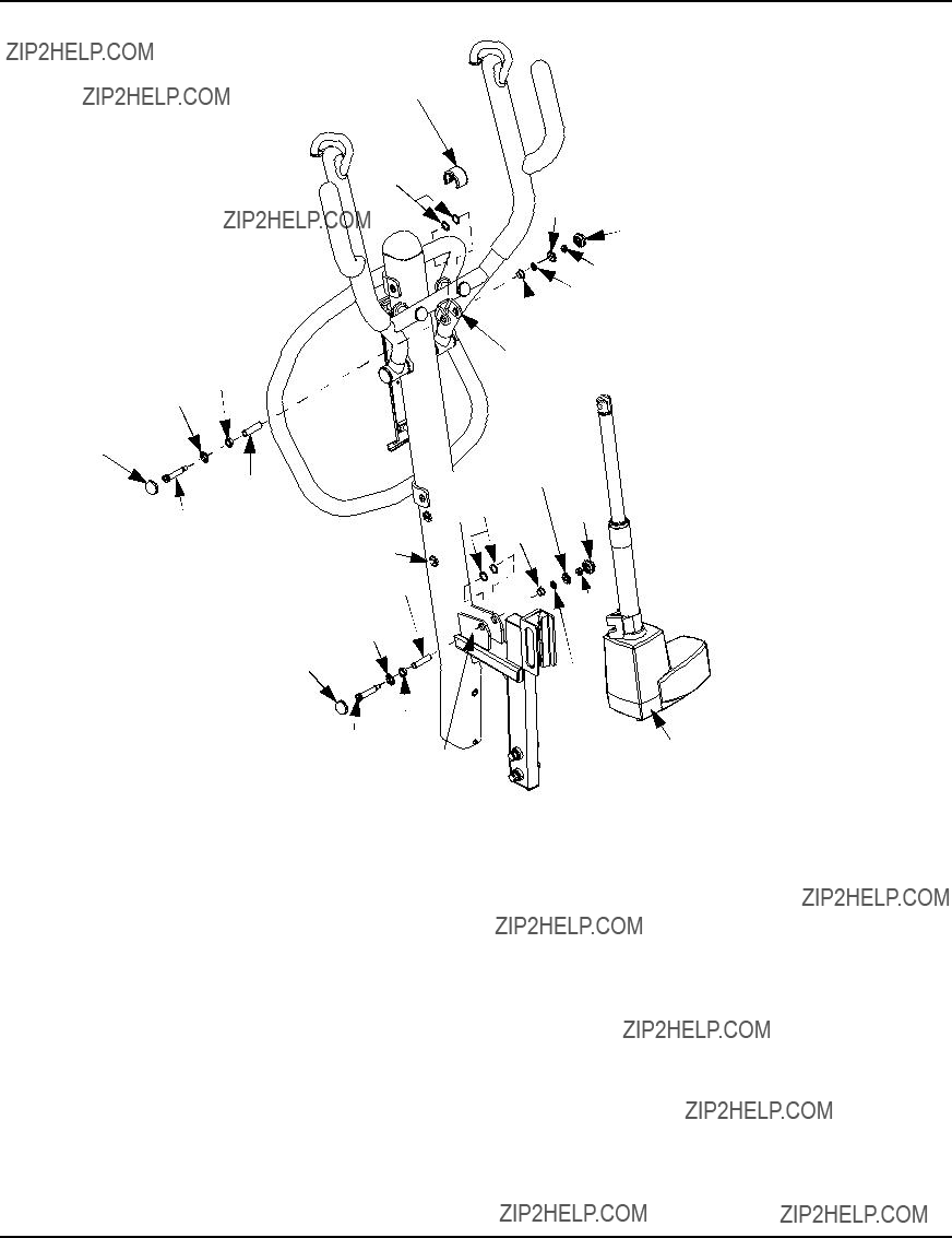
FIGURE 7.1 Replacing the Electric Actuator
Replacing the Leg Actuators
NOTE: For this procedure, refer to FIGURE 7.2 on page 25.
NOTE: If the legs of the patient lift do not open and close properly, it may be necessary to replace one or both of the leg actuators.
1.Test the operation of the legs:
???Press the CLOSE button on the hand control to close the legs.
???Press the OPEN button on the hand control to open the legs.
2.While holding on to the mast handles, carefully tip the patient lift back until it rests on the floor.
NOTE: It is necessary to remove both small base covers before removing the large base cover.
3.Remove the sixteen screws that attach the small base covers to the base.
4.Remove the eight pan head screws that attach the large base cover to the base.
NOTE: If the left or the right leg of the patient lift does not operate properly, perform the following steps on the side of the base necessary to replace the actuator. If both legs do not operate properly, perform this replacement procedure on both sides of the base.
5.Locate and disconnect the leg actuator lead wires.
SECTION 7???MAINTENANCE
NOTE: The actuator lead wires will be visible after the large base cover is removed.
6.Remove the socket head screw and washer that attach the leg actuator to the base.
7.At the other end of the actuator, remove the socket head screw and nut that attach the leg actuator to the leg bracket.
8.If necessary, repeat STEPS 5-7 on the opposite side of the base to remove the other leg actuator.
9.To replace the actuator(s), reverse STEPS 5-7.
Pan head screw (eight screws attach the
large base cover)
Leg
Screw
(eight screws attach each  small base cover)
Large Base Cover
Small Base Cover
Mast Handles
FIGURE 7.2 Replacing the Leg Actuators
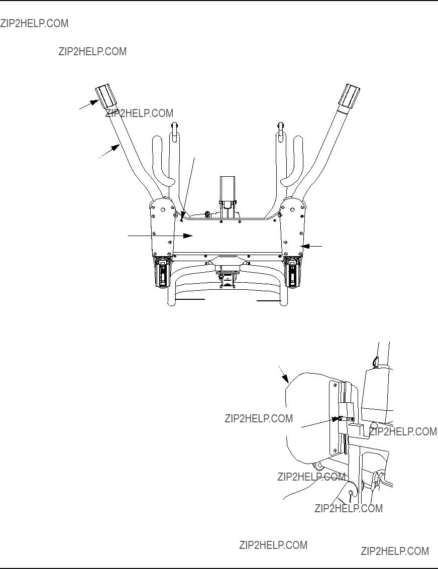
Adjusting the Knee Pad Height
NOTE: For this procedure, refer to FIGURE 7.3.
NOTE: When adjusted properly, the patient???s knee will make contact at the center of the knee pad.
1.While supporting the knee pad, disengage the quick release knob on the side of the knee pad mounting bracket.
2.Choose a height adjustment that will be comfortable for the patient and will provide the necessary support. Engage the quick release knob into position until the knee pad is secure in place.
Knee Pad
Quick Release
Knob
FIGURE 7.3 Adjusting the Knee Pad Height

LIMITED WARRANTY
PLEASE NOTE: THE WARRANTY BELOW HAS BEEN DRAFTED TO COMPLY WITH FEDERAL LAW
APPLICABLE TO PRODUCTS MANUFACTURED AFTER JULY 4, 1975. This warranty is extended only to the original purchaser/user of our products.
This warranty gives you specific legal rights and you may also have other legal rights which vary from state to state.
Invacare warrants the products manufactured to be free from defects in materials and workmanship for a period of five years on the lift and two years on the electric components from the date of purchase. If within such warranty period any such product shall be proven to be defective, such product shall be repaired or replaced, at Invacare???s option, with refurbished or new parts. This warranty does not include any labor or shipping charges incurred in replacement part installation or repair of any such product. Product
repairs shall not extend this warranty - coverage for repaired product shall end when this limited warranty terminates. Invacare???s sole obligation and your exclusive remedy under this warranty shall be limited to such repair and/or replacement.
For warranty service, please contact the dealer from whom you purchased your Invacare product. In the event you do not receive satisfactory warranty service, please write directly to Invacare at the address on the back cover, provide dealer???s name, address, date of purchase, indicate nature of the defect.
Invacare Corporation will issue a serialized return authorization. The defective unit or parts MUST be returned for warranty inspection using the serial number, when applicable as identification within 30 days of return authorization date. DO NOT return products to our factory without our prior consent. C.O.D. shipments will be refused; please prepay shipping charges.
LIMITATIONS AND EXCLUSIONS: THE FOREGOING WARRANTY SHALL NOT APPLY TO SERIAL
NUMBERED PRODUCTS IF THE SERIAL NUMBER HAS BEEN REMOVED OR DEFACED, PRODUCTS
SUBJECTED TO NEGLIGENCE, ACCIDENT, IMPROPER OPERATION, MAINTENANCE OR STORAGE,
PRODUCTS MODIFIED WITHOUT INVACARE???S EXPRESS WRITTEN CONSENT (INCLUDING, BUT
NOT LIMITED TO, MODIFICATION THROUGH THE USE OF UNAUTHORIZED PARTS OR
ATTACHMENTS; PRODUCTS DAMAGED BY REASON OF REPAIRS MADE TO ANY COMPONENT
WITHOUT THE SPECIFIC CONSENT OF INVACARE, OR TO A PRODUCT DAMAGED BY
CIRCUMSTANCES BEYOND INVACARE???S CONTROL, AND SUCH EVALUATION WILL BE SOLELY
DETERMINED BY INVACARE. THE WARRANTY SHALL NOT APPLY TO PROBLEMS ARISING FROM
NORMAL WEAR OR FAILURE TO ADHERE TO THE INSTRUCTIONS IN THIS MANUAL.
THE FOREGOING WARRANTY IS EXCLUSIVE AND IN LIEU OF ALL OTHER EXPRESS WARRANTIES.
IMPLIED WARRANTIES, IF ANY, INCLUDING THE IMPLIED WARRANTIES OF MERCHANTABILITY
AND FITNESS FOR A PARTICULAR PURPOSE, SHALL NOT EXTEND BEYOND THE DURATION OF THE
EXPRESSED WARRANTY PROVIDED HEREIN AND THE REMEDY FOR VIOLATIONS OF ANY IMPLIED
WARRANTY SHALL BE LIMITED TO REPAIR OR REPLACEMENT OF THE DEFECTIVE PRODUCT
PURSUANT TO THE TERMS CONTAINED HEREIN. INVACARE SHALL NOT BE LIABLE FOR ANY
CONSEQUENTIAL OR INCIDENTAL DAMAGES WHATSOEVER.
SOME STATES DO NOT ALLOW EXCLUSION OR LIMITATION OF INCIDENTAL OR CONSEQUENTIAL
DAMAGE, OR LIMITATION ON HOW LONG AN IMPLIED WARRANTY LASTS, SO THE ABOVE
EXCLUSIONS AND LIMITATIONS MAY NOT APPLY TO YOU.
THIS WARRANTY SHALL BE EXTENDED TO COMPLY WITH STATE OR PROVINCIAL LAWS AND
REQUIREMENTS.
Manuel d'utilisation et d'entretien du propri??taire
L??ve-personne
Roze???
D??TAILLANT : Ce manuel DOIT ??tre remis ?? l'utilisateur du l??ve-personne.
UTILISATEUR : Avant d'utiliser cet appareil, lisez ce manuel et gardez-le ?? titre de r??f??rence.
Pour de plus amples renseignements sur les  produits, les pi??ces et les services d???Invacare,
consultez notre site ?? l'adresse suivante : www.invacare.com
� MISE EN GARDE
NE FAITES PAS FONCTIONNER CET ??QUIPEMENT AVANT D'AVOIR LU ET
COMPRIS CE MANUEL. SI VOUS AVEZ DE LA DIFFICULT?? ?? COMPRENDRE
LES MISES EN GARDE, LES AVERTISSEMENTS ET LES DIRECTIVES,
COMMUNIQUEZ AVEC UN D??TAILLANT QUALIFI?? OU UN MEMBRE DU
SOUTIEN TECHNIQUE D'INVACARE AVANT DE TENTER D'UTILISER CET
??QUIPEMENT. SINON, DES BLESSURES OU DES DOMMAGES POURRAIENT
S'ENSUIVRE.
� MISE EN GARDE S'APPLIQUANT AUX ACCESSOIRES
Les produits Invacare sont con??us et fabriqu??s express??ment pour une utilisation avec les acces- soires Invacare. Les accessoires con??us par d???autres fabricants n???ont pas ??t?? test??s par Invacare. Il n???est donc pas recommand?? de les utiliser avec des produits Invacare.
L??GENDE DES SYMBOLES
?? ATTENTION, veuillez-vous r??f??rer aux directives d'utilisation. ??
MISE EN GARDE - Tenez TOUJOURS compte des bras du l??ve-personne. Des blessures au patient et/ou au pr??pos?? risquent de s'ensuivre.
MISE EN GARDE - Tenez TOUJOURS compte de l'appui-pieds, surtout de la position des pieds du patient sur cet appui-pieds. Des blessures au patient
et/ou au pr??pos?? risquent de s'ensuivre.
?? Date de la fabrication ??
L'appareil comprend des piles alcalines. NE jetez PAS les
piles dans les d??chets
YYYY m??nagers. Apportez-les dans un lieu destin?? ?? cet effet. Communiquez avec une entreprise de gestion de d??chets pr??s de votre r??gion pour obtenir de plus amples renseignements.
REMARQUES SP??CIALES
REMARQUES SP??CIALES
Les mots indicateurs utilis??s dans ce manuel s'appliquent aux risques ou aux pratiques dangereuses pouvant provoquer des blessures corporelles ou des dommages mat??riels. Consultez le tableau ci-dessous pour conna??tre la d??finition des mots-indicateurs.
� AVIS
L???INFORMATION CONTENUE DANS CE DOCUMENT PEUT ??TRE MODIFI??E SANS
PR??AVIS.
INTERF??RENCE AUX FR??QUENCES RADIO??LECTRIQUES
L???interf??rence aux radio fr??quences (IRF) influe sur la plupart des appareils ??lectroniques. AVERTISSEMENT Il faut ??tre prudent lorsqu???on utilise de l?????quipement de communication portatif ?? proximit?? de tels appareils. Si l'interf??rence aux fr??quences radio??lectriques entra??ne un comportement impr??visible, appuyez IMM??DIATEMENT sur le bouton d'urgence rouge. N'??TAIGNEZ PAS le bouton d'urgence rouge lorsque la transmission est en cours.
ENTRETIEN
Seule une personne qualifi??e DOIT ex??cuter l'entretien.
EMPLACEMENT DES ??TIQUETTES
EMPLACEMENT DES ??TIQUETTES
 AVERTISSEMENT
AVANT d???utiliser le l??ve-patient, pour assurer une utilisation ad??quate et une ex??cution s??curitaire de proc??dures,
LIRE et COMPRENDRE le manuel de l???utilisateur.
 AVERTISSEMENT
Limite de poids: 450 livres (204 Kg).
Le l??ve-patient Invacare N???EST PAS un appareil de transport.
NE PAS rouler par-dessus les rebords surface qui pourrait faire basculer le l??ve-patient.
NE PAS bloquer les roues du l??ve- patient lorsque vous soulevez un patient. Les roues doivent rest??es D??BLOQU??ES pour permettre au l??ve-patient de se stabiliser tout au long de la proc??dure de levage.
UTILISER SEULEMENT DES
TOILES ET DES ACCESSOIRES
DE LEVAGE AUTHENTIQUES
INVACARE.
Pour l???entretien et comme pi??ces de rechanges pour le l??ve-patient, N???UTILISEZ QUE les composants ad??quats.
Se r??f??rer au manuel de l???utilisateur pour les proc??dures d???entretien p??riodiques.
Customer Service: 1-800-333-6900
1160880 REV. A
REMARQUE: L'??tiquette de dimension de la toile est situ??e sur la barre transversale (non illustr??e)..
PARAM??TRES DU PRODUIT
PARAM??TRES DU PRODUIT
L??ve-personne Roze
REMARQUE: Selon la charge et l'utilisation.
SECTION 1???DIRECTIVES G??N??RALES
SECTION 1???DIRECTIVES G??N??RALES
� MISE EN GARDE
SECTION 1 - DIRECTIVES G??N??RALES contient des renseignements importants sur le fonctionnement et l'utilisation s??curitaire de ce produit.
Voyez ?? ce que toutes les pi??ces soient en bon ??tat avant d'utiliser l'appareil. Si les pi??ces sont endommag??es, N'UTILISEZ PAS l'appareil. Veuillez contacter le d??taillant pour de plus amples instructions.
Le l??ve-personne d'Invacare n'est PAS un dispositif de transport. Il est con??u pour transporter une personne d'une surface de repos ?? une autre (par exemple, d'un lit ?? un fauteuil roulant).
NE tentez PAS de transf??rer un patient sans l'accord de son m??decin, de l'infirmier
ou du pr??pos??. Lisez attentivement les instructions du manuel d'utilisateur, observez une ??quipe d'experts lors des proc??dures de soul??vement et ensuite effectuez l'ensemble de
la proc??dure plusieurs fois sous surveillance tandis qu'un personne en bonne sant?? joue le r??le du patient.
Les toiles pour soulever et transporter les patients d'Invacare sont sp??cifiquement con??ues pour ??tre utilis??es avec les l??ve-personnes station debout d'Invacare. Les toiles et accessoires con??us par d'autres fabricants ne doivent pas ??tre utilis??s comme composantes du syst??me de l??ve-personne d'Invacare. L'utilisation de ces produits est interdit et risque d'annuler la garantie associ??e au l??ve-personne. Utlisez la toile qui est recommand??e par le m??decin, l'infirmer ou le pr??pos?? du patient concern?? pour le confort et la s??curit?? du patient transport??.
Si l'ascenseur patient est utilis?? dans le secteur d'une douche ou d'un bain, garantir que l'ascenseur patient est essuy?? propre de n'importe quelle humidit?? apr??s l'usage. Ne PAS emmagasiner l'ascenseur dans un secteur humide ou dans une condition humide. P??riodiquement inspecter tous composants de l'ascenseur patient pour les signes de corrosion. Remplacer toutes parties qui sont corrod??es ou est endommag??.
Poids maximum
N'exc??dez JAMAIS le poids maximum pour chaque appareil. Le poids maximum du l??ve-personne Roze est de 450 lb.
Assemblage du l??ve-personne
NE serrez PAS excessivement l'??quipement de montage. Vous risquez d'ab??mer les supports de fixation. L'utilisation de la toile
Les personnes qui utilisent la toile station debout DOIVENT ??tre en mesure de supporter une part importante de leur propre poids sinon des blessures pourraient s'ensuivre.
Toiles station debout : N'UTILISEZ PAS la toile station debout avec le l??ve-personne comme dispositif de transport. Il est con??u pour transporter une personne d'une surface de repos ?? une autre (par exemple, d'un lit ?? un fauteuil roulant).
Toiles station debout : Avant de soulever le patient, assurez-vous que le bord inf??rieur de la toile station debout est plac?? au bas du dos du patient et que les bras du patient se trouvent ?? l'ext??rieur de la toile.
Toiles station debout : La ceinture DOIT ??tre s??rr??e mais le patient doit ??tre ?? l'aise, sinon, il pourrait glisser hors de la ceinture pendant le transfert et causer des blessures.
Toiles de transport : Avant de soulever le patient, assurez-vous que le bord inf??rieur de la toile de transport est plac?? au bas du dos du patient et que les bras du patient se trouvent ?? l'ext??rieur de la toile.
Toiles de transport : NE soulevez PAS le patient dans une position compl??tement ?? la verticale lors de l'utilisation de la toile de transport. Ceci pourrait causer des blessures.
Apr??s chaque lessive (selon les instructions sur l'??tiquette de la toile), inspectez les toiles pour vous assurer qu'il n'y ait pas d'usure, de d??chirures ou de d??cousures.
Des toiles jav??lis??es, d??chir??es, coup??es, effiloch??es ou bris??es ne sont pas s??curitaires et peuvent causer des blessures. Jetez-les imm??diatement.
NE modifiez PAS les toiles.
V??rifiez les attaches des toiles chaque fois qu'une toile est retir??e et remplac??e pour vous assurer qu'elle est bien en place avant que le patient soit d??plac?? d'un objet fixe (lit, chaise, chaise d'aisance).
Si le patient est en fauteuil roulant, enclenchez le blocage des roues afin de pr??venir le d??placement de la chaise.

SECTION 1???DIRECTIVES G??N??RALES
L'utilisation du l??ve-personne
Assurez-vous d'entendre le d??clic lors du montage de la pile sur le chargeur de pile pour vous assurer qu'elle est bien en place. Autrement, des blessures ou des dommages pourraient s???ensuivre.
Utilisez les poign??es pour pousser ou tirer le l??ve-personne.
Le soul??vement du patient
Avant de placer les jambes du l??ve-personne autour du patient, assurez-vous que les pieds du patient se trouvent hors de port??e de la palette du repose-pieds sinon des blessures pourraient s'ensuivre.
Les ajustements qui assurent la s??curit?? et le confort devraient ??tre effectu??s avant de d??placer le patient. Les bras du patient devraient se trouver ?? l'ext??rieur des courroies de la toile.
Avant de transf??rer un patient ?? partir d'un objet fixe (fauteuil roulant, chaise d'aisance ou lit), soulevez l??g??rement le patient de cet espace et v??rifiez que les attaches de la toile soient bien en place. Si une attache n'est pas fix??e correctement, abaissez le patient, rectifiez le probl??me et v??rifiez de nouveau.
Pendant le transfert, lorsque le patient est suspendu ?? une toile attach??e au l??ve-personne, NE passez PAS la base ?? roulettes sur ou quelconque surface in??gale qui pourrait cr??er un d??s??quilibre et faire tomber l'appareil. Utilisez les poign??es de direction du m??t EN TOUT TEMPS pour pousser et tirer le l??ve-personne.
Invacare recommande de verrouiller les roulettes pivotantes arri??res (SEULEMENT) quand vient le temps de fixer la toile autour du patient ou de la retirer (soulever ou transporter).
Invacare ne recommande PAS de verrouiller les roulettes arri??res du l??ve-personne quand vient le temps de soulever un patient. Cette pratique pourrait faire basculer le l??ve-personne et mettre le patient et les pr??pos??s en danger. Invacare RECOMMANDE que les roulettes arri??res soient d??verrouill??es quand vient le temps de soulever le patient pour permettre au l??ve-personne de se stabiliser lorsqu'on soul??ve un patient d'une chaise, d'un lit ou d'un objet fixe.
Le transfert d???un patient
Avant de transf??rer un patient, assurez-vous que le poids du patient ne d??passe pas le poids maximum de l'appareil.
Le blocage des roues du fauteuil roulant DOIT ??tre enclench?? avant d'abaisser le patient dans le fauteuil roulant aux fins de d??placement.
L'entretien
L'entretien r??gulier des l??ve-personnes et des accessoires est n??cessaire afin d'assurer un bon fonctionnement.
Apr??s les douze premiers mois d'utilisation, v??rifiez que les pivots et les attaches ne soient pas us??s. Si le m??tal est us??, la pi??ce DOIT ??tre remplac??e. Effectuez cette v??rification tous les six mois par la suite.
NE serrez PAS excessivement l'??quipement de montage. Vous risquez d'ab??mer les supports de fixation. Les roues et les boulons d'essieu requi??rent une inspection tous les six mois contre le serrage et l'usure.
SECTION 2???MONTAGE
Montage du l??ve-personne
Montage du m??t ?? la base
REMARQUE: Pour ette proc??dure, veuillez consulter la FIGURE 2.1.
REMARQUE: Pour ette proc??dure, veuillez consulter la Le montage du m??t peut ??tre retir?? de la base pour l'entreposage ou le transport. Le montage du m??t DOIT ??tre bien fix?? au montage de la base avant l'utilisation.
1.Placez la base sur une surface nivel??e pour assurer que toutes les roulettes touchent au sol.
2.Bloquez les roulettes arri??re (D??tail ?? A ??).
3.D??vissez le bouton sup??rieur et retirez-le de la base.
4.D??serrez le bouton inf??rieur, mais laissez-le viss?? dans la base.
Montage du m??t
DETAIL ???A???
Appuyez sur la languette pour BLOQUER
Bouton sup??rieur de plastique
5.Raccordez le c??ble de l???ensemble du m??t (non illustr??) au c??ble de la base (non illustr??).
6.Placez le tube de montage du m??t dans le trou de la base.
7.En soutenant le montage du m??t, serrez le bouton inf??rieur de plastique.
8.Vissez le bouton sup??rieur de plastique dans le trou de la base.
Montage du coussin pour genoux au montage de m??t
REMARQUE: Pour ette proc??dure, veuillez consulter la FIGURE 2.2.
REMARQUE: Le coussin pour genoux peut ??tre retir?? du l??ve-personne du patient pour l'entreposage ou le transport. Le coussin pour genoux DOIT ??tre solidement fix?? au montage du m??t avant son utilisation.
1.Poussez le coussin pour genoux en position sur le support de fixation du coussin pour genoux sur le montage du m??t.
2.Mettez le bloc de fixation en place sur le support de fixation du coussin pour genoux.
3.Ins??rez la poign??e de blocage rapide dans le support de fixation, le coussin pour genoux et le bloc de fixation.
4.Resserrez la poign??e de blocage rapide.
Montage du repose-pieds au montage du m??t
REMARQUE: Pour ette proc??dure, veuillez consulter la FIGURE 2.3.
1.Tournez le repose-pieds vers le haut et placez les crochets du repose-pieds sur le dessus des boulons de fixation dans le montage du m??t.
2.Tournez le repose-pieds vers le bas vers le montage du m??t. La base de la palette de repose-pieds reposera sur les boulons du montage du m??t.
3.Assurez-vous que le repose-pied soit de niveau et bien s??curis??e.
FIGURE 2.2 Montage du coussin pour genoux au montage de m??t
Boulon de fixation inf??rieur
FIGURE 2.3 Montage du repose-pieds au montage du m??t
La fixation du support de chargeur de pile au mur
NOTE: Pour cette proc??dure, se r??f??rer ?? la FIGURE 2.4.
1.Placez le support de chargeur de batterie au mur ?? la position souhait??e.
2.?? l'aide d'un crayon, marquez la position du trou du milieu.
3. Mesurez 6?? pouces au bas du trait de crayon et percez un trou de montage.
4.Installez la vis de montage inf??rieure jusqu'?? ce qu'il y ait un ??cart d'environ 1/8 de pouces entre la t??te de la vis et le mur.
5.Placez le support de chargeur de pile au bas de la vis de montage inf??rieure.
6.Percez les deux autres trous de montage.
7.Vissez les vis de montage ?? travers le support de chargeur de pile et dans le mur. Resserrez fermement.
 Support de fixation
Vis de

 fixation
Assurez-vous d'entendre le d??clic lors du montage de la pile sur le chargeur pour vous assurer qu'elle
est bien en place. Autrement, des blessures ou des FIGURE 2.4 La fixation du support de chargeur de pile au mur dommages pourraient s???ensuivre.
8.Placez le chargeur de pile sur le support de fixation.
9.Branchez le chargeur de pile dans une prise ??lectrique.
REMARQUE: Une lumi??re DEL s'allumera lorsque le chargeur de pile est aliment??.
La fixation du chargeur de pile au m??t
� MISE EN GARDE
Si le chargeur de pile est fix?? au m??t et qu'il est branch?? dans une prise ??lectrique, assurez-vous de d??brancher le chargeur de pile de la prise ??lectrique AVANT d'utiliser le l??ve-personne. ?? d??faut de quoi, des blessures ou des dommages pourraient s???ensuivre.
La pile et le chargeur de pile montr??s ?? leur  emplacement sur le
m??t
REMARQUE: Pour ette proc??dure, veuillez consulter la
FIGURE 2.5FIGURE 2.5.
1.Retirez les deux pi??ces de Mylar recouvrant les trous de montage du chargeur de pile derri??re le m??t.
2.Ins??rez les vis de fondation dans les trous de montage.
4.Placez le support de chargeur de pile sur les vis de fondation.
5.Chargez la pile. Consultez la section Le chargement de la pile ?? la page 39.
SECTION 3???FONCTIONNEMENT
SECTION 3???FONCTIONNEMENT
� MISE EN GARDE
NE tentez PAS de transf??rer un patient sans l'accord de son m??decin, d'un infirmier ou d'un pr??pos??. Lisez attentivement les instructions contenues dans le manuel d'utilisateur, observez une ??quipe d'experts lors des proc??dures de soul??vement et effectuez ensuite la proc??dure plusieurs fois sous surveillance ?? l'aide d'une personne en bonne sant?? jouant le r??le du patient.
Les jambes du l??ve-personne DOIVENT ??tre ouvertes le plus possible afin d'assurer une stabilit?? et une s??curit?? sup??rieures. Si le patient est dans une toile et qu'il devient n??cessaire de circuler dans un passage ??troit, fermer les jambes du l??ve-personne aussi longtemps qu'il faut ex??cuter cette man??u- vre. Quand le l??ve-personne a fini de circuler dans le passage, remettre les jambes ?? la position ouverte maximale.
REMARQUE:L'utilisation d'un seul pr??pos?? repose sur l'??valuation faite par le professionnel de la sant?? au cas par cas.
Le fonctionnement du l??ve-personne
REMARQUE: Pour cette proc??dure, se r??f??rer ?? la FIGURE 3.1.
Le blocage/d??blocage des roulettes arri??res
REMARQUE: Pour cette proc??dure, se r??f??rer ?? la Detail ???A???.
???Pour bloquer la roulette : appuyez sur la languette.
???Pour d??bloquer la roulette : tirez sur la languette.
Le soul??vement/l'abaissement du l??ve-personne
REMARQUE: Pour cette proc??dure, se r??f??rer ?? la Detail ???B???.
???Pour soulever le l??ve-personne : appuyez sur le bouton UP (???) de la commande manuelle.
REMARQUE:Si le l??ve-personne est soulev?? au plus haut point, il se peut qu'une l??g??re pression soit n??cessaire pour abaisser le m??t. Poussez l??g??rement sur les deux bras du l??ve-personne en m??me temps pour ??viter de faire basculer le l??ve-personne.
???Pour abaisser le l??ve-personne : appuyez sur le bouton down (???) de la commande manuelle.
La fermeture/l'ouverture des jambes
REMARQUE: Pour cette proc??dure, se r??f??rer ?? la Detail ???B???.
???Pour fermer les jambes : appuyez sur le bouton close de la commande manuelle.
???Pour ouvrir les jambes : appuyez sur le bouton open de la commande manuelle.
L'utilisation de l'arr??t d'urgence
REMARQUE: Pour cette proc??dure, se r??f??rer ?? la Detail ???C???.
???Appuyez sur le bouton d'urgence ROUGE pour ??viter que les bras du l??ve-personne se l??vent ou s'abaissent.
???Pour r??initialiser, tournez le bouton d'urgence dans le sens horaire.
DETAIL ?? A ?? - LE BLOCAGE/D??BLOCAGE DES
ROUES ARRI??RES
Appuyez sur la languette (DOWN) en position LOCK (verrouillage)
DETAIL ?? B ?? - D??TAILS DE LA COMMANDE
MANUELLE
Bouton Up
Bouton Down


 Bouton Close Legs
Bouton Open
Legs
 Commande Manuelle
DETAIL ?? C ?? - ARR??T D'URGENCE
Bouton d'urgence
Appuyez pour l'arr??ter, tournez dans le sens 
horaire pour r??initialiser.
FIGURE 3.1 Le fonctionnement du l??ve-personne
SECTION 3???FONCTIONNEMENT
L'activation du d??verrouillage m??canique d'urgence
D??verrouillage d'urgence primaire
REMARQUE: Pour cette proc??dure, se r??f??rer ?? la FIGURE 3.2.
REMARQUE:Cette proc??dure fait monter ou descendre la membrure si la commande manuelle fait d??faut.
Pour activer le d??verrouillage d'urgence primaire, ins??rez un stylo dans le trou portant l'??tiquette Urgence monter et Urgence descendre de la bo??te de commande.
D??verrouillage d'urgence secondaire
REMARQUE: Pour cette proc??dure, se r??f??rer ?? la FIGURE 3.3.
REMARQUE:Tous les actionneurs du l??ve-personne sont munis d'un d??verrouillage d'urgence m??canique. Le d??verrouillage m??canique permet ?? l'actionneur de se replier sans alimentation.
REMARQUE:Utilisez le d??verrouillage d'urgence primaire avant d'avoir recours ?? la proc??dure du d??verouillage d'urgence secondaire. Vous devriez appliquer cette proc??dure uniquement si le d??verrouillage d'urgence primaire ne fonctionne pas ou s'il est inaccessible.
REMARQUE:Le l??ve-personne DOIT ??tre charg?? pour que le d??verrouillage m??canique fonctionne.
Pour activer le d??verrouillage d'urgence secondaire, tirez sur la poign??e d'urgence ROUGE et appuyez simultan??ment sur la membrure.
Le chargement de la pile
REMARQUE: Pour cette proc??dure, se r??f??rer ?? la FIGURE 3.4.
REMARQUE:Invacare recommande de charger la pile chaque jour pour en prolonger la dur??e.
REMARQUE:Une alarme se fait entendre lorsque la pile est faible.
1.Tirez la poign??e ?? l'arri??re de la pile vers le haut (UP).
2.Soulevez la pile hors de la bo??te de commande.
FIGURE 3.2 D??verrouillage d'urgence primaire
Poign??e d'urgence
ROUGE
� AVERTISSEMENT
Assurez-vous d'entendre le d??clic lors du montage de la pile sur le chargeur de pile pour confirmer qu'elle est bien en place. Autrement, des blessures ou des dommages pourraient s???ensuivre.
3.Placez la pile sur le chargeur de pile. Enfoncez la partie sup??rieure de la pile contre le support de fixation jusqu'?? ce qu'un d??clic se fasse entendre.
REMARQUE:La DEL de chargement s'allume. Une fois le chargement termin??, la DEL s'??teint.
REMARQUE:Le chargement complet prend environ quatre heures.
4.Tirez la poign??e ?? l'arri??re de la pile vers le haut (UP).
5.Soulevez la pile hors du chargeur de pile..
� AVERTISSEMENT
Assurez-vous d'entendre le d??clic lors du montage de la pile sur la bo??te de commande pour con- firmer qu'elle est bien en place. Autrement, des blessures ou des dommages pourraient s???ensuivre.
6.Placez la pile sur la bo??te de commande. Enfoncez la partie sup??rieure de la pile contre le support de fixation jusqu'?? ce qu'un d??clic se fasse entendre.
FIGURE 3.3 D??verrouillage d'urgence secondaire
Un d??clic se fait entendre si l'installation est correcte (??TAPES 3 et 6)
FIGURE 3.4 Le chargement de la pile
SECTION 4???LE SOUL??VEMENT DU PATIENT
SECTION 4???LE SOUL??VEMENT DU PATIENT
� MISE EN GARDE
NE d??passez PAS la limite de poids de 450 lbs.
Ne tentez PAS de transf??rer un patient sans l'accord de son m??decin, de l'infirmier ou du pr??pos??.
??loignez TOUJOURS les mains et les doigts des pi??ces mobiles pour ??viter les blessures.
Les toiles Invacare sont con??ues sp??cifiquement pour ??tre utilis??es avec les l??ve-personnes d'Invacare. Afin d'assurer la s??curit?? du patient, N'UTILISEZ PAS de toiles ou de l??ve-personnes provenant de diff??rents fabricants.
Les personnes qui utilisent la toile station debout DOIVENT ??tre en mesure de supporter une part importante de leur propre poids sinon des blessures pourraient s'ensuivre.
Avant de soulever le patient, assurez-vous que le bord inf??rieur de la toile station debout est plac?? au bas du dos du patient et que les bras du patient se trouvent ?? l'ext??rieur de la toile. La ceinture DOIT ??tre s??rr??e mais le patient doit ??tre ?? l'aise, sinon, il pourrait glisser hors de la ceinture pendant le transfert et causer des blessures.
Apr??s CHAQUE lessive (selon les instructions de lavage inscrites sur la toile), examinez la toile pour toute usure, des d??chirures ou des d??cousures. Jetez IMM??DIATEMENT toute toile qui pr??sente ces ??l??ments.
Toute toile jav??lis??e, d??chir??e, coup??e, effiloch??e ou bris??e est dangereuse et risque de causer des blessures ou des dommages. Jetez IMM??DIATEMENT toute toile qui pr??sente ces ??l??ments.
NE modifiez PAS les toiles des patients.
NE d??placez PAS le patient si la toile n'est pas bien fix??e aux points d'ancrage du l??ve-personne. V??rifiez que la toile est bien fix??e aux points d'ancrage AVANT de soulever le patient.
En mode transfert, quand le patient est suspendu dans la toile, ??VITEZ de rouler la base du l??ve-personne sur surface in??gale qui risquent d'entra??ner l'instabilit?? du l??ve-personne.
Utilisez la poign??e de commande sur le m??t en tout temps pour pousser ou tirer le l??ve-personne.
REMARQUE: Consulter le manuel du propri??taire de la toile, num??ro de pi??ce 102891 pour de plus amples renseignements.
REMARQUE: Invacare recommande que deux pr??pos??s soient pr??sents et participent ?? TOUTE proc??dure de soul??vement.
Fixation du l??ve-personne
REMARQUE: Pour cette proc??dure, se r??f??rer ?? la FIGURE 4.1.
REMARQUE: Consultez les directives g??n??rales Directives g??n??rales ?? la page 42 avant de proc??der et respectez toutes les avertissements.
REMARQUE: Avant de positionner les jambes du l??ve-personne sous un lit, assurez-vous que l'endroit est libre d'obstacles.
SECTION 4???LE SOUL??VEMENT DU PATIENT
� AVERTISSEMENT
Les jambes du l??ve-personne DOIVENT ??tre ouvertes le plus possible afin d'assurer une stabilit?? et une s??curit?? sup??rieures. Si vous devez fermer les jambes pour placer le l??ve-personne sous un lit, fermez-les pendant que vous positionnez l'appareil et soulevez le patient hors du lit. Lorsque les jambes du l??ve-personne ne sont plus sous le lit, ouvrez-les de nouveau.
1.Appuyez sur le bouton open legs de la commande manuelle pour ouvrir les jambes du l??ve-personne?? la position maximale.
2.Fixez le l??ve-personne ?? l'aide de la poign??e du m??t.
3.Appuyez sur le bouton ayant une fl??che vers le bas de la commande manuelle pour abaisser les l??ves-bras afin de les ajuster facilement ?? la toile.
4.Abaissez le l??ve-personne pour faciliter la fixation de la toile.
Bouton UP 

Bouton DOWN
Bouton Open Legs 


 Bouton Close Legs
 Commande manuelle
FIGURE 4.1 Boutons de Commande Manuelle
Le soul??vement du patient
� AVERTISSEMENT
NE d??passez PAS la limite de poids de 450 lbs.
Les personnes qui utilisent la toile station debout DOIVENT ??tre en mesure de supporter une part importante de leur propre poids sinon des blessures pourraient s'ensuivre.
N'ENCLENCHEZ PAS le blocage des roulettes arri??res du l??ve-personne lorsque vous soulevez une personne. Le blocage des roulettes arri??res pourrait faire basculer le l??ve-personne et mettre le patient et les pr??pos??s en danger. Le d??verrouillage des roulettes arri??res en cours de soul??vement du patient permet au l??ve-personne de se stabiliser tandis qu'on soul??ve le patient ?? partir d'un fauteuil roulant, d'un lit ou d'un objet fixe.
NE d??placez PAS le patient si la toile n'est pas bien fix??e aux points d'ancrage du l??ve-personne. Assurez-vous que la toile est bien fix??e AVANT de soulever le patient. Si une des attaches n'est pas correctement en place, rectifiez le probl??me. Quand la toile est soulev??e de quelques pouces et ??loign??e d'une surface stable, et avant de d??placer le patient, v??rifiez une fois de plus pour vous assurer que la toile et les attaches sont bien fix??es en place. Si vous d??couvrez un probl??me, abaissez le patient vers la surface stable et rectifiez le probl??me, sinon des blessures ou des dommages pourraient s'ensuivre.
SECTION 4???LE SOUL??VEMENT DU PATIENT
Les ajustements qui assurent la s??curit?? et le confort devraient ??tre effectu??s avant de d??placer le patient.
Les toiles Invacare sont con??ues sp??cifiquement pour ??tre utilis??es avec les l??ve-personnes d'Invac- are. Afin d'assurer la s??curit?? du patient, N'UTILISEZ PAS de toiles ou de l??ve-personnes provenant de diff??rents fabricants.
REMARQUE: Pour cette proc??dure, se r??f??rer ?? la FIGURE 4.2 ?? la page 43.
REMARQUE: Le patient DOIT ??tre avant tout en position assise. Utilisez la t??te du lit pour amener le patient en position assise. D??placez ensuite les jambes sur le c??t?? du lit.
1.Demandez au patient de s'agripper aux poign??es d'appui de chaque c??t?? du l??ve-personne (D??tail ?? A ?? de la FIGURE 4.2).
2.Demandez au patient de s'appuyer le dos contre la toile de transport.
� AVERTISSEMENT
Toiles de transport - Avant de soulever le patient, assurez-vous que le bord inf??rieur de la toile de transport est plac?? au bas du dos du patient et que les bras du patient se trouvent ?? l'ext??rieur de la toile.
Toiles de transfert - Avant de soulever le patient, assurez-vous que le bord inf??rieur de la toile de transfert est plac?? au bas du dos du patient et que les bras du patient se trouvent ?? l'ext??rieur de la toile.
3.Assurez-vous de ce qui suit :
A.Les genoux du patient sont bien s??curis??s contre les coussins pour genoux.
B.Les pieds du patient sont bien plac??s sur le repose-pieds.
C.Toiles :
???Toiles de transport - le bord inf??rieur de la toile de transport est plac?? au bas du dos du patient.
???Toiles de transfert - le bord inf??rieur de la toile de transfert est plac?? au bas du dos du patient.
???L'une ou l'autre des toiles - les bras du patient se trouvent ?? l'ext??rieur de la toile.
D.Les roulettes arri??res sont d??verrouill??es.
E.Les jambes se trouvent dans la position d'ouverture maximale.
� AVERTISSEMENT
Pour transf??rer un patient ?? partir d'un fauteuil roulant, les roulettes de celui-ci DOIVENT demeurer verrouill??es avant d'abaisser le patient dans le fauteuil roulant. Sinon, des blessures pourraient s'ensuivre.
4.Pour transf??rer un patient ?? partir d'un fauteuil roulant, verrouillez le syst??me de blocage de roulettes du fauteuil roulant (D??tail ?? B ?? de la FIGURE 4.2).
5.Appuyez sur le bouton arrow UP de la commande manuelle pour soulever le patient au-dessus de la surface (lit, fauteuil roulant ou toilette). Le l??ve-personne doit supporter tout le poids du patient (D??tail ?? C ?? de la FIGURE 4.2).
REMARQUE: Le champ de gravit?? inf??rieur offre une stabilit?? pour que le patient se sente plus en s??curit?? et que le l??ve-personne soit plus facile ?? d??placer.
DETAIL ?? C ?? - LE SOUL??VEMENT
DU PATIENT
 Coussin pour genoux
 Repose-pieds
Roulettes
Toile
FIGURE 4.2 Le soul??vement du patient
D??placer le patient
� MISE EN GARDE
Les jambes du l??ve-personne DOIVENT ??tre ouvertes le plus possible afin d'assurer une stabilit?? et une s??curit?? sup??rieures. Si le patient se trouve dans une toile et il s'av??re n??cessaire de le faire passer dans un espace ??troit, refermez les jambes du l??ve-personne aussi longtemps qu'il le faut pour franchir cet espace. Une fois cet espace franchi, remettez les jambes du l??ve-personne ?? la position d'ouverture maximale.
Lors du d??placement d'un patient suspendu dans la toile, NE passez PAS les roulettes sur surface in??gale qui pourrait cr??er un d??s??quilibre. Le l??ve-personne pourrait basculer. Utilisez la poign??e du m??t en tout temps pour pousser ou tirer le l??ve-personne.
1.Assurez-vous que les jambes du l??ve-personne sont ouvertes en position maximale. Si non, appuyez sur le bouton OPEN LEGS sur la commande manuelle pour ouvrir les jambes ?? la position ouverte maximale.
2.??loignez le l??ve-personne de la surface de soul??vement.
3.D??placez le patient lentement vers la surface d??sir??e.

SECTION 5???LE TRANSFERT D'UN PATIENT
SECTION 5???LE TRANSFERT D'UN PATIENT
� AVERTISSEMENT
N'ESSAYEZ PAS de transf??rer un patient sans l'accord de son m??decin, de l'infirmier ou du pr??pos??.
NE d??placez JAMAIS le patient si la toile n'est pas rattach??e correctement aux points d'ancrage sur le l??ve-personne. V??rifiez que la toile est correctement fix??e aux points d'ancrage avant de lever le patient. Si une des attaches n'est pas correctement en place, rectifiez le probl??me. Lorsque la toile est soulev??e quelques pouces au-dessus de la surface stationnaire et avant de d??placer le patient, v??rifiez de nouveau pour vous assurer que toutes les attaches sont correctes. Si l'une des attaches n'est pas correctement en place, replacez le patient sur la surface stationnaire et corrigez le probl??me pour ??viter des blessures.
Les ajustements qui assurent la s??curit?? et le confort devraient ??tre effectu??s avant de d??placer le patient. Les bras du patient devraient se trouver ?? l???ext??rieur des courroies.
N'UTILISEZ PAS de toiles ou de l??ve-personnes de diff??rents fabricants. Les toiles Invacare sont con??ues sp??cifiquement pour ??tre utilis??es avec les l??ve-personnes d'Invacare. Autrement, des blessures ou des dommages pourraient s???ensuivre.
N'ENCLENCHEZ PAS le blocage des roues arri??res du l??ve-personne lorsque vous soulevez une personne. Le blocage des roulettes arri??re pourraient faire basculer le l??ve-personne et mettre le patient et les pr??pos??s en danger.
Les jambes du l??ve-personne DOIVENT ??tre ouvertes le plus possible afin d'assurer une stabilit?? et une s??curit?? sup??rieures. Si le patient est dans une toile et il s'av??re n??cessaire de franchir un passage ??troit, refermez les jambes du l??ve-personne pour effectuer cette transition. Lorsque le l??ve-personne a franchi le passage, remettez les jambes ?? la position ouverte maximale. Si vous devez fermer les jambes pour placer le l??ve-personne sous un lit, fermez-les pendant que vous positionnez l'appareil et soulevez le patient hors du lit. Lorsque les jambes du l??ve-personne ne sont plus sous le lit, ouvrez-les de nouveau.
Examinez les attaches de la toile chaque fois qu'elle est retir??e et remise en place pour vous assurer qu'elle est bien fix??e avant de d??placer le patient d'un endroit ?? un autre.
L'aide d'un seul pr??pos?? repose sur l'??valuation du professionnel de la sant?? et du cas par cas.

SECTION 5???LE TRANSFERT D'UN PATIENT
Transfert vers une toilette
� AVERTISSEMENT
Invacare recommande de verrouiller les roulettes pivotantes arri??re uniquement au moment d'installer le patient dans la toile et de l'en retirer.
REMARQUE: Pour cette proc??dure, se r??f??rer ?? la FIGURE 5.1.
1. Soulevez le patient ?? partir du c??t?? du lit.
2. Appuyez sur le bouton MONTER de la commande manuelle pour soulever le patient jusqu'?? ce ses bras soient ??loign??s de la chaise d'aisance. Le poids du patient sera maintenu par le l??ve-personne.
3. Guidez le patient vers la chaise d'aisance. Cette ??tape pourrait exiger deux pr??pos??s.
4. Appuyez sur le bouton arrow down pour abaisser le patient sur la toilette.
5. Verrouillez les roulettes pivotantes arri??re du l??ve-personne.
6. Ex??cutez l'une des man??uvres suivantes :
??? Toile debout - d??crochez la toile debout de ses points d'attache sur le l??ve-personne.
??? Toile de transport -
iii.Si d??sir??, d??crochez la toile de transport des points d'attache sup??rieurs sur le l??ve-personne.
REMARQUE: Le patient peut demeurer dans la partie sup??rieure de la toile de transport tandis qu'il utilise la toilette.
7.Dites au patient de retirer ses pieds de l'appui-pieds ou aidez-le ?? le faire.
8.Retirez la toile qui entoure le patient.
9.D??verrouillez les roulettes arri??re et ??loignez le l??ve-personne de la toilette.
10.Une fois termin??, assurez-vous de nouveau que les attaches soient bien en place.
11.Pour soulever le patient de la toilette.
SECTION 5???LE TRANSFERT D'UN PATIENT
Le transfert vers un fauteuil roulant
REMARQUE: Pour cette proc??dure, se r??f??rer ?? la FIGURE 5.2.
1.Assurez-vous que les jambes du l??ve-personne soient ouvertes lorsque le patient est suspendu ?? l'aide du l??ve-personne. Appuyez sur le bouton pour ouvrir les jambes jusqu'?? leur position maximale.
2.Positionnez le fauteuil roulant.
3.Enclenchez le blocage des roues du fauteuil roulant pour ??viter tout mouvement de la chaise (D??tail ?? A ??).
� AVERTISSEMENT
NE placez PAS le patient dans le fauteuil roulant sans que le blocage soit enclench??. Le blocage des roues du fauteuil roulant DOIT ??tre enclench?? avant d'abaisser le patient dans le fauteuil roulant aux fins de d??placement. Autrement, des bles- sures ou des dommages pourraient s???ensuivre.
4.Placez le patient au-dessus du fauteuil roulant (D??tail ?? B ??).
5.Appuyez sur le bouton arrow down pour abaisser le patient dans le fauteuil roulant..
� AVERTISSEMENT
Verrouillez les roulettes pivotantes arri??re SEULEMENT au moment de placer ou de retirer la toile (debout ou transfert) du patient. Sinon, des blessures pourraient s'ensuivre.
6.Verrouillez les roulettes pivotantes arri??re.
7.D??crochez la toile de tous ses points d'attache sur le l??ve-personne.
8.Dites au patient de lever les pieds de la palette d'appui-pieds. Aidez le patient ?? le faire au besoin.
9.Retirez la toile qui entoure le patient.
10.D??verrouillez les roulettes arri??res et ??loignez le l??ve-personne du fauteuil roulant.
Transfert du patient vers un lit
DETAIL ?? A ??
Dispositif de blocage de roue
DETAIL ???B???
FIGURE 5.2 Le transfert vers un fauteuil roulant
REMARQUE: Le champ de gravit?? inf??rieur offre une stabilit?? pour que le patient se sente plus en s??curit?? et que le l??ve-personne soit plus facile ?? d??placer.
1.Placez le patient le plus loin possible au milieu du lit.
REMARQUE: Si on transf??re le patient d'une surface inf??rieure ?? celle du lit, appuyez sur le bouton up arrow pour soulever le patient au-dessus de la surface du lit. Le patient devrait se trouver soulev?? ?? une hauteur d??gag??e du lit tandis qu'il est soulev?? dans la toile.
2.Appuyez sur le bouton down arrow et abaissez le patient sur le lit.
� AVERTISSEMENT
Invacare recommande de verrouiller les roulettes pivotantes arri??re UNIQUEMENT au moment d'installer le patient dans la toile et de l'en retirer.
3.Verrouillez les roulettes pivotantes arri??re.
4.D??crochez la toile debout ou de transport de tous les points d'attache qui la retiennent au l??ve-personne.
5.Dites au patient de lever les pieds du repose-pieds.
REMARQUE: Aidez le patient ?? le faire au besoin.
6.Retirez la toile debout ou de transport autour du patient.
7.D??verrouillez les roulettes arri??re et ??loignez le l??ve-personne du lit.
SECTION 6???D??PANNAGE
SECTION 6???D??PANNAGE
REMARQUE: Si les probl??mes persistent ?? la suite des actions sugg??r??es, communiquez avec votre d??taillant ou Invacare.
SECTION 7???ENTRETIEN
SECTION 7???ENTRETIEN
Liste de contr??le de l???entretien
REMARQUE:Respectez les proc??dures d'entretien qui figurent dans ce manuel afin d'assurer le fonctionnement continu de votre l??ve-personne.
Gr??ce ?? sa conception sup??rieure, le l??ve-personne d'Invacare vous offre un service s??curitaire et efficace ?? la hauteur de vos attentes avec peu d'entretien.
Bien que toutes les pi??ces du l??ve-personne d'Invacare soient faites ?? partir d'acier de la meilleure qualit??, un contact m??tal sur m??tal provoque une usure ?? la longue.
Le seul ajustement ou entretien des roulettes qui soit n??cessaire est le nettoyage, la lubrification et la v??rification des essieux et des boulons. Retirez tous les d??bris, etc. de la roue et des tourillons pivotants. Si une pi??ce est us??e, remplacez-la IMM??DIATEMENT.
Si vous doutez de la s??curit?? d'une quelconque pi??ce du l??ve-personne, communiquez IMM??DIATEMENT avec votre d??taillant

SECTION 7???ENTRETIEN
Nettoyage de la toile et du l??ve-personne
La toile devrait ??tre lav??e r??guli??rement dans une eau dont la temp??rature n'exc??de pas 180 ??F (82 ??C) et une solution biologique. Le nettoyage du l??ve-personne n'exige qu'un chiffon souple mouill?? ?? l'eau et une petite quantit?? de savon doux. Le l??ve-personne peut ??tre nettoy?? ?? l'aide de nettoyants non abrasifs.
D??tection de l'usure et de l'endommagement
Il est essentiel d'examiner toutes les pi??ces contraintes tel que les toiles, les bras de soul??vement et tout pivot de l??ve-personne qui d??montrent des signes de craquement, d'effilochement, de d??formation ou de d??t??rioration. Remplacez toute pi??ce d??fectueuse IMM??DIATEMENT et assurez-vous que le l??ve-personne ne soit pas utilis?? jusqu'?? ce qu'il soit r??par??.
La lubrification du l??ve-personne
Le l??ve-personne d'Invacare est con??u pour un entretien minimal. Toutefois, la v??rification et la lubrification tous les six (6) mois assurent une s??curit?? et une fiabilit?? continues.
Maintenez le l??ve-personne et les toiles propres et en bonne condition. Vous devez noter toute d??fectuosit?? et en aviser votre d??taillant dans les plus brefs d??lais.
Les roulettes DOIVENT pivoter et rouler avec aisance. On peut appliquer une graisse l??g??re (un lubrifiant pour voitures ?? l'??preuve de l'eau) au tourillon pivotant ?? bille des roulettes une fois par ann??e. Appliquez plus fr??quemment si les roulettes sont sujettes ?? des conditions d'humidit?? extr??mes.
Remplacement de l'actionneur ??lectrique
REMARQUE: Pour cette proc??dure, se r??f??rer ?? la FIGURE 7.1 ?? la page 50.
1.D??branchez l'actionneur de la membrure de la bo??te de commande du m??t. Passez le fil de l'actionneur ?? travers le trou d'acheminement pour le fil de l'actionneur dans le m??t.
2.Retirez l'??quipement qui fixe la partie sup??rieure de l'actionneur de la membrure au support de fixation de l'actionneur de la membrure.
A.Retirez les capuchons de caoutchouc de l'??crou et de la vis qui retiennent l'actionneur ??lectrique au support de fixation de l'actionneur du bras du l??ve-personne.
B.Retirez la vis, la rondelle de marche, le coussinet, la rondelle, le capuchon d'actionneur, la bague, la rondelle de marche, la rondelle plate et l'??crou.
REMARQUE:Le capuchon de l'actionneur se d??sserrera au moment de retirer les ferrures attach??es. Examinez le capuchon d'actionneur pour y d??celer des dommages. Remplacez le capuchon d'actionneur si vous voyez qu'il est endommag??.
3.Retirez l'??quipement qui fixe la partie inf??rieure de l'actionneur de la membrure au support de fixation de l'actionneur de la membrure.
A.Retirez les capuchons de caoutchouc de l'??crou et de la vis qui retiennent l'actionneur ??lectrique au support de fixation de l'actionneur du bras du l??ve-personne.
B.Retirez la vis, la rondelle de marche, le coussinet, la rondelle, le capuchon d'actionneur, la bague, la rondelle de marche, la rondelle plate et l'??crou.
4.Pour remplacer l'actionneur ??lectrique, renversez les ??TAPES 1 ?? 3.
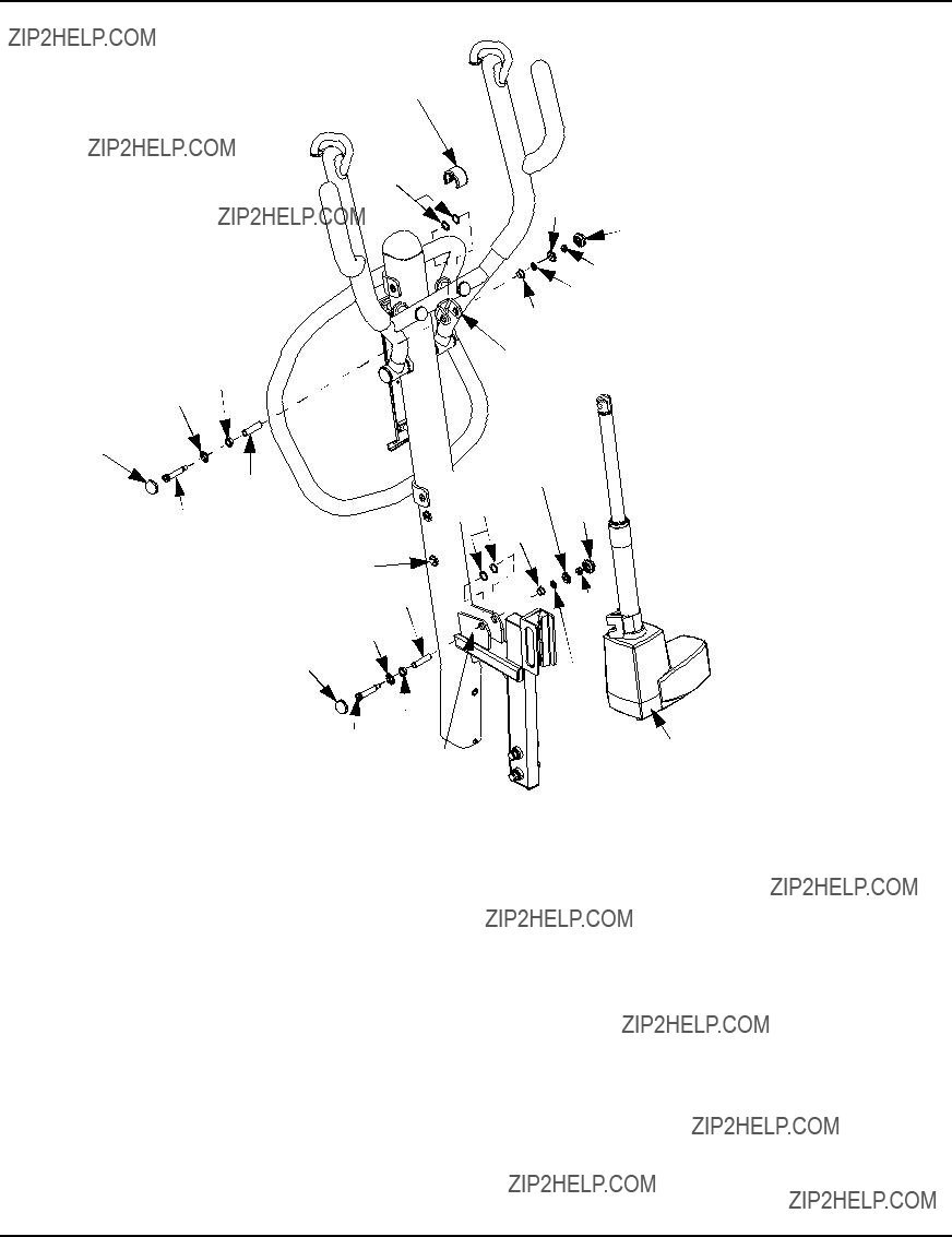
FIGURE 7.1 Remplacement de l'actionneur ??lectrique
Remplacement des actionneurs de jambes
REMARQUE: Pour cette proc??dure, se r??f??rer ?? la FIGURE 7.2 ?? la page 51.
REMARQUE:Si les jambes du l??ve-personne ne s'ouvrent et ne se ferment pas correctement, vous devrez sans doute remplacer les actionneurs d'une ou des deux jambes.
1.Assurez-vous que les jambes fonctionnent correctement :
???Appuyez sur le bouton de la commande manuelle pour FERMER les jambes.
???Appuyez sur le bouton de la commande manuelle pour OUVRIR les jambes.
2.En tenant les poign??es du m??t, inclinez soigneusement le l??ve-personne jusqu'?? ce qu'il s'appuie au sol.
REMARQUE : Vous devez retirer les deux petits capuchons de la base avant de retirer le grand capuchon de la base.
3.Retirez les 16 vis qui fixent les petits couvercles ?? la base.
4.Enlevez les huit vis ?? t??te cylindrique qui fixent le grand capuchon de la base ?? la base.
REMARQUE : Si la jambe gauche ou la jambe droite du l??ve-personne ne fonctionne pas correctement, ex??cutez les ??tapes inscrites sur le c??t?? de la base pour remplacer l'actionneur. Si les deux jambes ne fonctionnent pas correctement, proc??dez de cette fa??on pour remplacer des deux c??t??s de la base.
5.Rep??rez et d??branchez les fils de l'actionneur de la jambe.
SECTION 7???ENTRETIEN
REMARQUE : Les fils de l'actionneur sont visibles lorsque vous aurez retir?? le grand capuchon de la base.
6.Enlevez la vis ?? pans creux et la rondelle qui fixent la jambe de l'actionneur ?? la base.
7.?? l'autre extr??mit?? de l'actionneur, retirez la vis ?? pans creux et l'??crou qui fixent l'actionneur de la jambe au support de la jambe.
8.Au besoin, r??p??tez les ??TAPES 5-7 de l'autre c??t?? de la base pour retirer l'autre actionneur de la jambe.
9.Si vous devez remplacer les actionneurs, inversez les ??TAPES 5-7.
Vis ?? t??te cylindrique (huit vis fixent le grand
capuchon de la base)
Jambe
Vis (huit vis fixent chaque
 petit capuchon de la base)
Grand capuchon de la base
 Petit capuchon de la base
 Poign??es du m??t
FIGURE 7.2 Remplacement des actionneurs de jambes
R??glage de la hauteur du coussin pour genoux
REMARQUE: Pour cette proc??dure, se r??f??rer ?? la FIGURE 7.3.
REMARQUE: Lorsqu'il est bien r??gl??, le genou du patient entre en contact direct avec le coussin de genoux.
1.Tout en retenant le coussin de genou, d??gagez la poign??e de blocage rapide sur le c??t?? du support de fixation du coussin de genoux.
2.Choisissez un r??glage de hauteur qui assure le confort du patient et qui lui procure le support appropri??. Mettez la poign??e de blocage rapide en position jusqu'?? ce que le coussin de genoux soit bien fix?? en place.
Knee Pad
Quick Release Knob 
FIGURE 7.3 R??glage de la hauteur du coussin pour genoux
GARANTIE LIMIT??E
Cette garantie est valable uniquement pour l'acheteur/utilisateur original de nos produits.
Cette garantie vous donne des droits l??gaux sp??cifiques. Vous pouvez jouir d'autres droits qui s'appliquent d'une province ?? l'autre.
Invacare garantit que les produits fabriqu??s sont libres de toutes d??fectuosit??s quant aux mat??riaux et ?? la fabrication pour une p??riode de cinq ans en ce qui a trait au l??ve-personne et d'un an pour les composantes ??lectriques et ceci, ?? partir de la date d'achat. Si, au cours de la p??riode de garantie, un produit est jug?? d??fectueux, il sera r??par?? ou remplac?? ?? la discr??tion d???Invacare, avec partie r??nov?? ou nouvelle. Cette garantie ne comprend pas la main-d?????uvre ou les frais d???exp??dition encourus pour le remplacement de pi??ces ou la r??paration dudit produit. L???unique obligation d???Invacare et votre recours exclusif dans cette garantie se limitera ?? une telle r??paration et/ou un tel remplacement.
Pour le service au titre de la garantie, communiquez avec le d??taillant chez qui vous avez achet?? le produit Invacare. Les r??parations de produit n'??tendront pas cette garantie - la couverture pour le produit r??par?? terminera quand cette garantie limit??e termine. En cas d???insatisfaction ?? l?????gard du service au titre de la garantie, ??crivez directement ?? Invacare ?? l???adresse qui figure sur la quatri??me de couverture en indiquant le nom et l'adresse du d??taillant, la date d'achat et la nature du d??faut.
Invacare Corporation ??mettra une autorisation de retour avec num??ro de s??rie. L'unit?? ou la pi??ce d??fectueuse DOIT ??tre retourn??e pour une inspection de garantie et doit renfermer son num??ro de s??rie, le cas ??ch??ant, aux fins d'identification dans les trente jours suivant la date d'autorisation du retour. NE retournez PAS de produits ?? notre usine sans autorisation pr??alable de notre part. Les envois contre remboursement (C.O.D) seront refus??s ; veuillez pr??payer les frais d'envoi.
LIMITES ET EXCLUSIONS : LA GARANTIE SUSMENTIONN??E NE S'APPLIQUE PAS AUX PRODUITS
DONT LE NUM??RO DE S??RIE A ??T?? RETIR?? OU MODIFI?? ; AUX PRODUITS QUI ONT FAIT L'OBJET DE
N??GLIGENCE OU D'ACCIDENT, D'UNE MAUVAISE UTILISATION, D'UN MAUVAIS ENTRETIEN OU
D'UN MAUVAIS ENTREPOSAGE ; AUX PRODUITS MODIFI??S SANS L'ACCORD ??CRIT D'INVACARE, Y
COMPRIS, SANS S'Y LIMITER, LA MODIFICATION AU MOYEN DE PI??CES OU DE RALLONGES NON
AUTORIS??ES ; AUX PRODUITS ENDOMMAG??S ?? LA SUITE DE R??PARATIONS DE TOUTES
COMPOSANTES SANS L'ACCORD SP??CIFIQUE D'INVACARE ; AUX PRODUITS ENDOMMAG??S DANS
DES CIRCONSTANCES HORS DU CONTR??LE D'INVACARE. UNE TELLE ??VALUATION NE SERA FAITE
QUE PAR INVACARE. CETTE GARANTIE NE S'APPLIQUE PAS ?? DES PROBL??MES DUS ?? L'USURE
NORMALE OU AU NON-RESPECT DES INSTRUCTIONS CONTENUES DANS CE MANUEL.
LA GARANTIE SUSMENTIONN??E EST EXCLUSIVE ET REMPLACE TOUTE AUTRE GARANTIE. LES
GARANTIES IMPLICITES, S'IL Y A LIEU, COMPRENNENT LES GARANTIES IMPLICITES DE QUALIT??
MARCHANDE ET D???APTITUDE ?? UN USAGE PARTICULIER, NE S'??TENDRA PAS AU-DEL?? DE LA
DUR??E DE LA GARANTIE MENTIONN??E DANS LA PR??SENTE ET L???UNIQUE RECOURS EN CAS DE
VIOLATION DE QUELCONQUE GARANTIE SERA LIMIT?? ?? LA R??PARATION OU AU REMPLACEMENT
DU PRODUIT D??FECTUEUX CONFORM??MENT AUX CONDITIONS ??NONC??ES DANS LA PR??SENTE.
INVACARE N'EST PAS RESPONSABLE DES DOMMAGES INDIRECTS OU ACCESSOIRES, QUELS QU???ILS
SOIENT.
CERTAINS ??TATS/PROVINCES NE PERMETTENT PAS D'EXCLUSION OU DE LIMITATION DES
DOMMAGES INDIRECTS OU ACCESSOIRES OU DES LIMITATIONS SUR LA DUR??E DE VIE D'UNE
GARANTIE RESTREINTE ; AINSI, LES EXCLUSIONS ET LIMITATIONS MENTIONN??ES CI-DESSUS
PEUVENT NE PAS S'APPLIQUER DANS VOTRE CAS.
CETTE GARANTIE SERA ??TENDUE POUR RESPECTER LES LOIS ET R??GLEMENTS
PROVINCIAUX/D'??TAT.
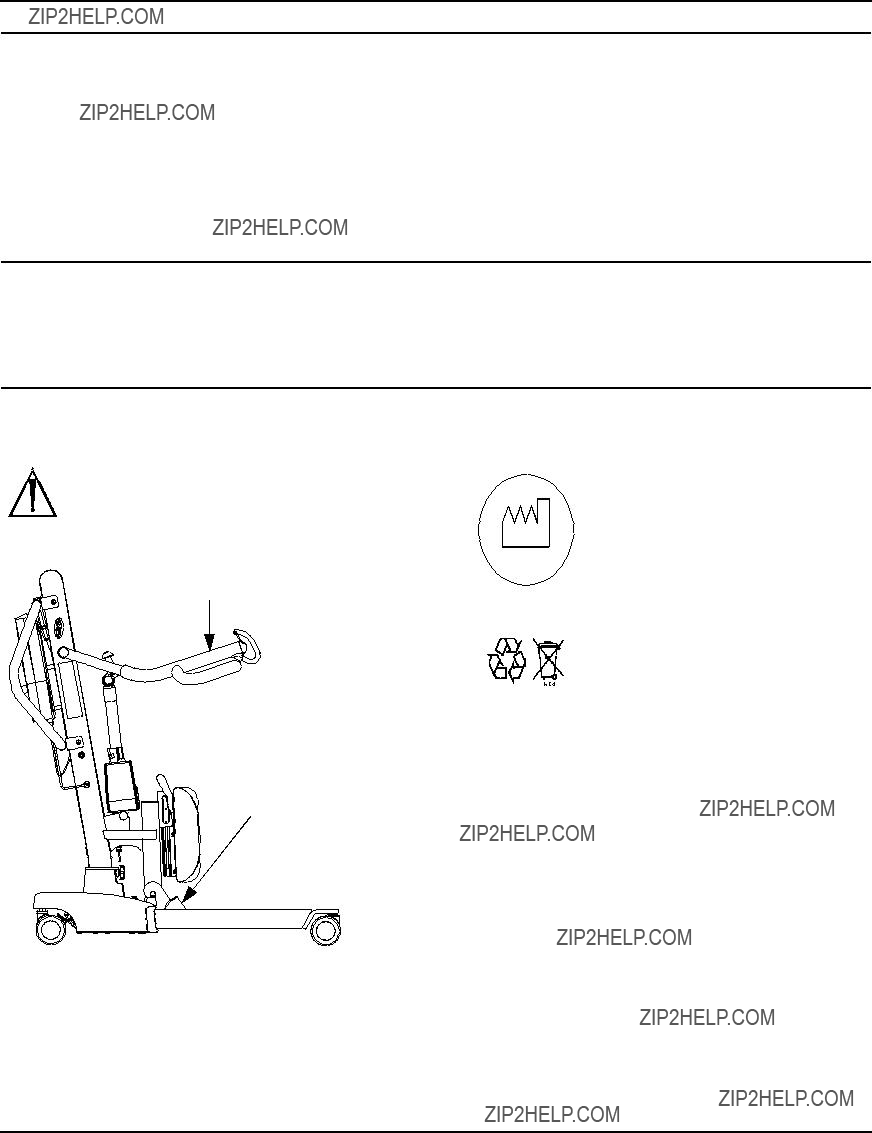


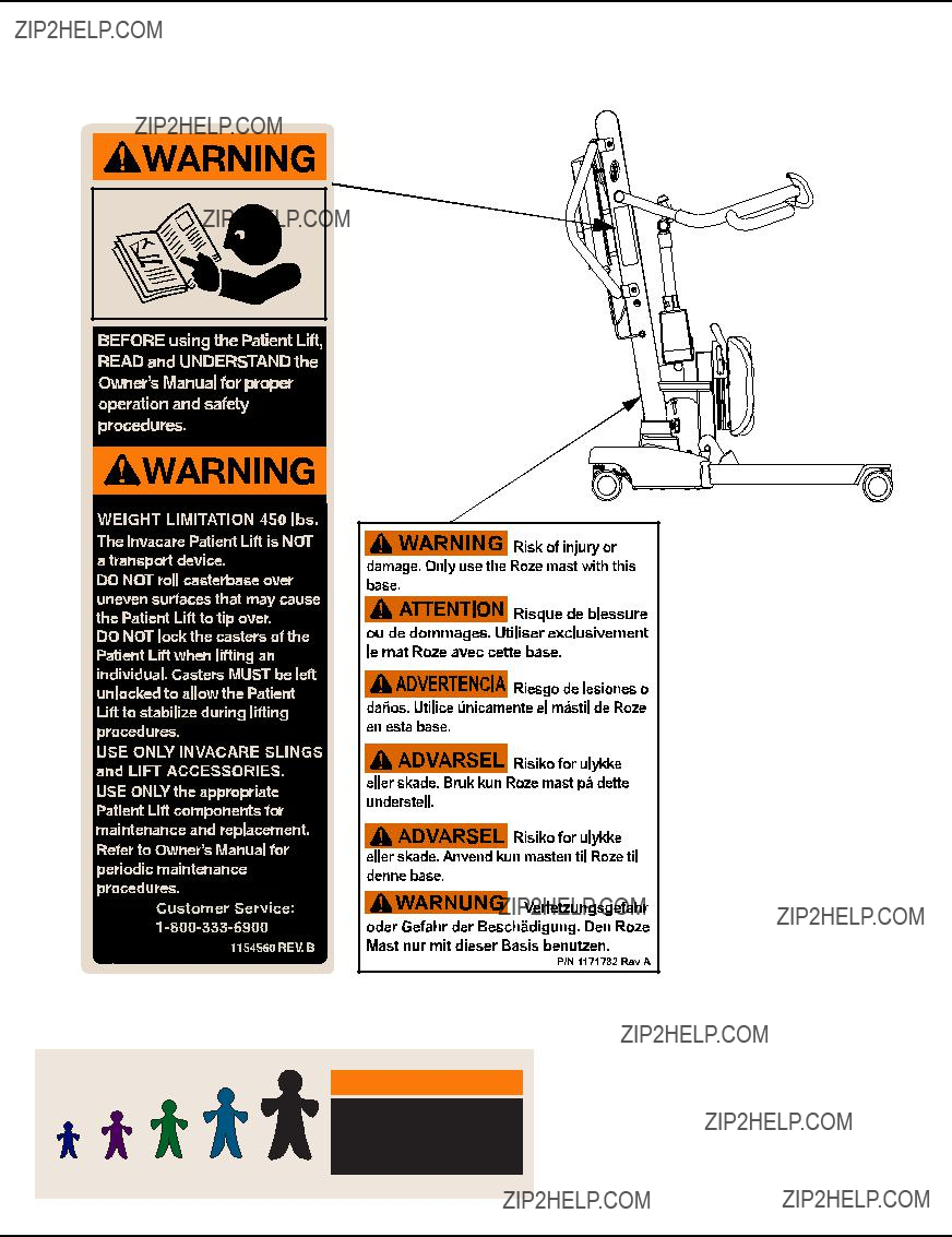


 to UNLOCK. Base
 (shown in place)