
Head and Torso Supports
Assembly, Installation and Operating Instructions
Model Nos. 1164, 3040 (Torso Supports) and
Model Nos. 3045, 3046 (Head Supports)
SAVE THESE INSTRUCTIONS
SAFETY SUMMARY
WARNING/CAUTION notices as used in this manual apply to hazards or unsafe practices which could result in personal injury or property damage.
NOTICE
The information contained in this document is subject to change without notice.
WARNING
DO NOT install, maintain or operate this equipment without reading, understanding and following the proper instructions otherwise injury or damage may result.
Make certain ALL screws, bolts and nuts are tight at all times.
PARTS LIST
NOTE: Items with (*), upholstery style and color MUST BE supplied with Part No. when ordering replacement parts.
INSTALLATION
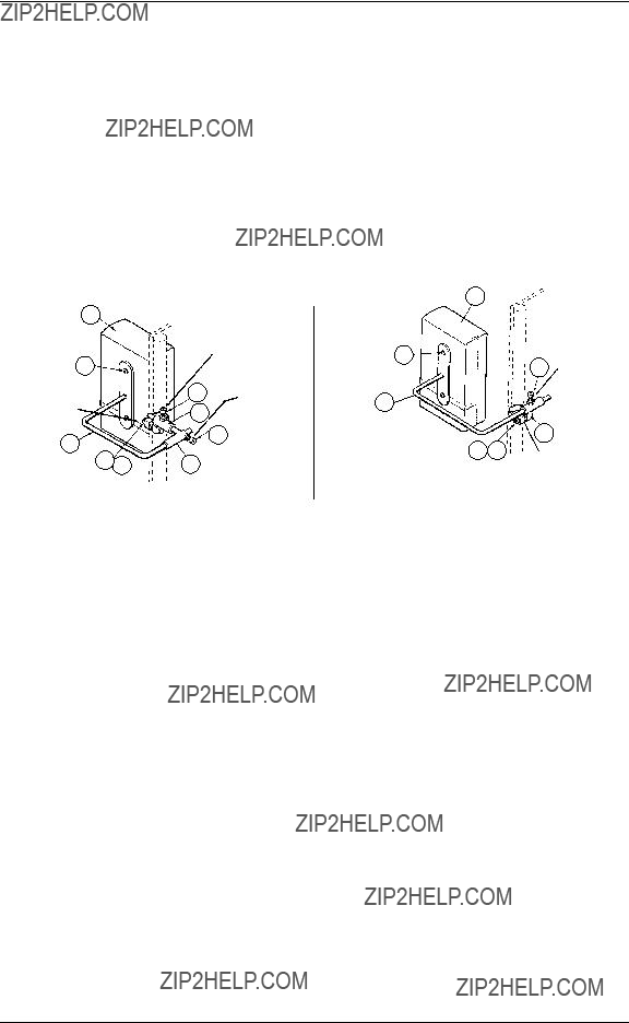
HEAD SUPPORTS MODEL NOS. 3045 AND 3046 (FIGURE 1)
1.Mount the headrest support to the back upright of the chair; which includes the following items:
Headrest/Torso Pad Assembly (Item 1) Panhead Screw (Item 2)
Pad Support Sub-Assembly (Item 12 or 13) Socket Screw (Item 6)
Bracket Clamp (Item 7)
Adjustment Bracket Assembly (Item 9)
Lug Screw (Item 10)
Locknut (Item 11)
2.LEFT or RIGHT adjustments can be accomplished by loosening the socket screw (Item 6) on the adjustable bracket assembly (Item 9 - Model No. 3045) (Item 7 - Model 3046) with an Allen wrench.
3.UP or DOWN adjustment are made by loosening the lug screw and the locknut (Items 10 and 11).
4.FRONT and BACK adjustments are made by loosening the socket screw (Item 6) on the bracket clamp (Item 7 - Model No. 3045 Only).
FIGURE 1 - INSTALLATION OF HEAD SUPPORTS
TORSO SUPPORTS MODEL NOS. 1164 AND 3040 (FIGURE 2)
1.Mount the torso support to the back upright of the chair; which includes the following items:
Headrest/Torso Pad Assembly (Item 1) Panhead Screw (Item 2)
Torso Bracket Cover (Item 3) (Model No. 1164 - Only) Support Rod (Item 4)
Socket Screw (Item 6)
Torso Support Bracket (Item 5) Pad Support Sub-Assembly (Item 8) Bracket Clamp (Item 7)
Lug Screw (Item 10) Locknut (Item 11)
2.LEFT or RIGHT adjustments can be accomplished by loosening the socket screw (Item 6) on the bracket clamp (Item 7 - Model No. 3040 and the support rod
(Item 4 - Model No. 1164) with an Allen wrench.
NOTE: The support rod (Item 4) MUST BE assembled to the torso support bracket (Item 5) before installation of Model No. 1164.
3.UP or DOWN adjustment are made by loosening the lug screw and the locknut (Items 10 and 11).
4.FRONT and BACK adjustments are made by loosening the socket screw (Item 6) on the bracket clamp (Item 7 - Model No. 1164 Only).
NOTE: Model No. 3040 has no front-to-back adjustment.
TORSO SUPPORTS
NOTE: Items with (*), upholstery style and color MUST BE supplied with Part No. when ordering replacement parts.