INSTRUCTION MANUAL
VHF TRANSCEIVER
iF50
UHF TRANSCEIVER
iF60
This device complies with Part 15 of the FCC rules. Operation is subject to the condition that this device does not cause harmful interference.
INSTRUCTION MANUAL
VHF TRANSCEIVER
iF50
UHF TRANSCEIVER
iF60
This device complies with Part 15 of the FCC rules. Operation is subject to the condition that this device does not cause harmful interference.

SAFETY TRAINING INFORMATION
Your Icom radio generates RF electromagnetic energy during transmit mode. This radio is designed for and clas- sified as ???Occupational Use Only???, meaning it must be used only during the course of employment by individuals aware of the hazards, and the ways to minimize such haz- ards. This radio is NOT intended for use by the ???General Population??? in an uncontrolled environment.
This radio has been tested and complies with the FCC RF exposure lim- its for ???Occupational Use Only???. In addition, your Icom radio complies with the following Standards and Guidelines with regard to RF energy and electromagnetic energy levels and evaluation of such levels for exposure to humans:
???FCC OET Bulletin 65 Edition
???American National Standards Institute
???American National Standards Institute
???The following accessories are authorized for use with this product. Use of accessories other than those speci???ed may result in RF ex- posure levels exceeding the FCC requirements for wireless RF ex- posure.; Belt Clip
To ensure that your expose to RF electromagnetic energy is within the FCC allowable limits for occupa- tional use, always adhere to the following guidelines:
CAU TION
i
???DO NOT operate the radio without a proper antenna attached, as this may damaged the radio and may also cause you to exceed FCC RF exposure limits. A proper antenna is the antenna supplied with this radio by the manufacturer or antenna speci???cally authorized by the manufacturer for use with this radio.
???DO NOT transmit for more than 50% of total radio use time (???50% duty cycle???). Transmitting more than 50% of the time can cause FCC RF exposure compliance requirements to be exceeded. The radio is transmitting when the ???TX indicator??? lights red. You can cause the radio to transmit by pressing the ???PTT??? switch.
???ALWAYS keep the antenna at least 2.5 cm (1 inch) away from the body when transmitting and only use the Icom
The information listed above provides the user with the information needed to make him or her aware of RF exposure, and what to do to as- sure that this radio operates with the FCC RF exposure limits of this radio.
Electromagnetic Interference/Compatibility
During transmissions, your Icom radio generates RF energy that can pos- sibly cause interference with other devices or systems. To avoid such in- terference, turn off the radio in areas where signs are posted to do so. DO NOT operate the transmitter in areas that are sensitive to electro- magnetic radiation such as hospitals, aircraft, and blasting sites.
Occupational/Controlled Use
The radio transmitter is used in situations in which persons are exposed as consequence of their employment provided those persons are fully aware of the potential for exposure and can exercise control over their exposure.
ii

FOREWORD
READ ALL INSTRUCTIONS carefully and completely before using the transceiver.
SAVE THIS INSTRUCTION MANUAL??? This instruction manual contains important operating instructions for the
EXPLICIT DEFINITIONS
PRECAUTION
R WARNING! NEVER hold the transceiver so that the antenna is very close to, or touching exposed parts of the body, especially the face or eyes, while transmitting. The transceiver will perform best if the microphone is 5 to 10 cm (2 to 4 inches) away from the lips and the transceiver is vertical.
R WARNING! NEVER operate the transceiver with a headset or other audio accessories at high volume levels.
CAUTION! NEVER short the terminals of the battery pack.
NEVER connect the transceiver to a power source other than the
RWARNING
Personal injury, fire hazard or electric shock may occur.
DO NOT push the PTT when not actually desiring to transmit.
AVOID using or placing the transceiver in direct sunlight or in areas with temperatures below
CAUTION Equipment damage may occur.
(+140??F).
NOTE
If disregarded, inconvenience only. No risk of personal injury, fire or electric shock.
DO NOT modify the transceiver for any reason.
MAKE SURE the ???exible antenna and battery pack are securely attached to the transceiver, and that the antenna and battery pack are dry before attachment. Exposing the inside of the transceiver to water will result in serious damage to the transceiver.
OPERATING NOTES
???When transmitting with a portable radio, hold the radio in a vertical position with its microphone 5 to 10 centimeters (2 to 4 inches) away from your mouth. Keep the antenna at least 2.5 centimeters (1 inch) from your head and body.
???If you wear a portable
The use of
FCC caution:
Changes or modi???cations to this device, not expressly approved by Icom Inc., could void your authority to operate this transceiver under FCC regulations.

TABLE OF CONTENTS
SAFETY TRAINING INFORMATION ?????????????????????????????????????????? i FOREWORD ???????????????????????????????????????????????????????????????????????? iii EXPLICIT DEFINITIONS ????????????????????????????????????????????????????????? iii OPERATING NOTES ???????????????????????????????????????????????????????????? iii PRECAUTION ????????????????????????????????????????????????????????????????????? iv TABLE OF CONTENTS ????????????????????????????????????????????????????????? v SUPPLIED ACCESSORIES ??????????????????????????????????????????????????? vi
1 ACCESSORIES ???????????????????????????????????????????????????????????????
???Accessory attachments ?????????????????????????????????????????????????????? 1
2 PANEL DESCRIPTION ???????????????????????????????????????????????????
???Front, top and side panels ???????????????????????????????????????????????? 3
???Function display ??????????????????????????????????????????????????????????????? 6
???Programmable function keys ????????????????????????????????????????????? 7
3 CONVENTIONAL OPERATION ???????????????????????????????????????
???Turning power ON ????????????????????????????????????????????????????????? 12
???Channel selection ????????????????????????????????????????????????????????? 12
???Call procedure ??????????????????????????????????????????????????????????????? 13
??? Receiving and transmitting ????????????????????????????????????????????? 14
???Scrambler function ????????????????????????????????????????????????????????? 17
???User set mode ??????????????????????????????????????????????????????????????? 18
4 BIIS OPERATION ?????????????????????????????????????????????????????????
???Default setting ??????????????????????????????????????????????????????????????? 19
???Receiving a call ???????????????????????????????????????????????????????????? 20
???Transmitting a call ????????????????????????????????????????????????????????? 23
???Receiving a message ?????????????????????????????????????????????????????? 26
???Transmitting a status ?????????????????????????????????????????????????????? 29
???Transmitting an SDM ?????????????????????????????????????????????????????? 30
???Position data transmission ???????????????????????????????????????????????? 31
???Printer connection ????????????????????????????????????????????????????????? 32
???PC connection ??????????????????????????????????????????????????????????????? 32
???Digital ANI ????????????????????????????????????????????????????????????????????? 32
???Auto emergency transmission ?????????????????????????????????????????? 33
???Stun function?????????????????????????????????????????????????????????????????? 33
???BIIS indication ??????????????????????????????????????????????????????????????? 34
??? Priority A channel selection ????????????????????????????????????????????? 34
v
5 BATTERY CHARGING ????????????????????????????????????????????????
???Battery charging ???????????????????????????????????????????????????????????? 35
???Caution ???????????????????????????????????????????????????????????????????????? 36
???Optional battery chargers ???????????????????????????????????????????????? 37
???Optional battery case ?????????????????????????????????????????????????????? 43
6
???Optional
???Attachment ?????????????????????????????????????????????????????????????????? 46
7 OPTIONS ??????????????????????????????????????????????????????????????????
*There are no names on the programmable function keys since the functions can be freely assigned to [P0] to [P3], [Red], [ ] and [
 ] keys.
Attach the supplied function name stickers above the appropriate keys for easy recognition of that key???s assigned function.
vi
1 ACCESSORIES
??? Accessory attachments
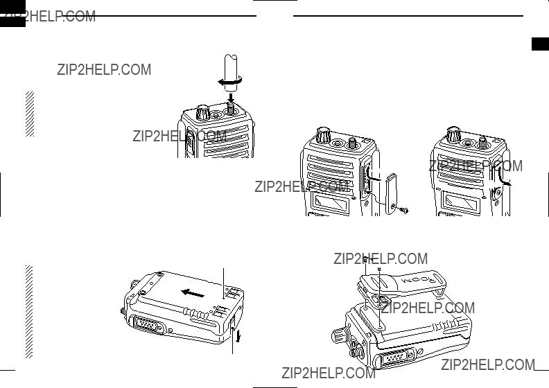
D Flexible antenna
Connect the supplied ???exible antenna to the antenna connector.
CAUTION!
??? NEVER HOLD by the antenna when carrying the transceiver.
??? Transmitting without an antenna may damage the transceiver.
?? Battery pack
To attach the battery pack:
Slide the battery pack on the back of the transceiver in the direc- tion of the arrow (q), then lock it with the battery release button.
???Slide the battery pack until the battery release button makes a ???click??? sound.
To release the battery pack:
Push the battery release button in the direction of the arrow (w) as shown below. The battery pack is then released.
ACCESSORIES 1
?? Jack cover
Attach the jack cover when the optional
q
r
 e
e
w
D Belt clip
Attach the belt clip to the back of the transceiver with the supplied screws.
1
NEVER release or at- tach the battery pack when the transceiver is wet or soiled. This may result water or dust getting into the transceiver/battery pack and may result in the transceiver being damaged.
1
Battery pack
q
w
Battery release button
 Supplied screws
2

2 PANEL DESCRIPTION
??? Front, top and side panels
y
NOTE: If the speaker netting (for dust proo???ng) becomes wet, dry it with a hair drier (cool mode) etc. before operating the transceiver. Otherwise the audio may be dif???cult to hear for loss of the sound pressure.
Turns power ON and adjusts the audio level.
w RED BUTTON
The desired function can be assigned by your dealer.
e ANTENNA CONNECTOR
Connects the supplied antenna.
r
Connects the optional
[SP MIC] jack cover
NOTE: KEEP the [SP MIC] jack cover attached to the transceiver when the speaker- microphone is not used.
(See p. 2 for details)
t
The desired functions can be assigned independently by your dealer.
y CH UP AND DOWN KEYS [ ]/[
]/[ ]
]
???During standby condition, push to select an operating channel.
???After pushing [TX Code CH Select], push to select a TX code channel.
???After pushing [DTMF Autodial], push to select a DTMF channel.
???After pushing and holding [Scan A Start/Stop]/[Scan B Start/Stop], push to select a scan group.
???After pushing [Digital], push to select a BIIS code, status num-
ber or SDM.
*Desired functions can be assigned independently by your dealer.
??? Continue to the next page.
2 PANEL DESCRIPTION
??? Front, top and side panels (Continued)
u TRANSMIT/BUSY INDICATOR
Lights red while transmitting; lights green while receiving a sig- nal, or when the squelch is open.
i PTT SWITCH [PTT]
??? Push and hold to transmit; release to receive.
PANEL DESCRIPTION 2
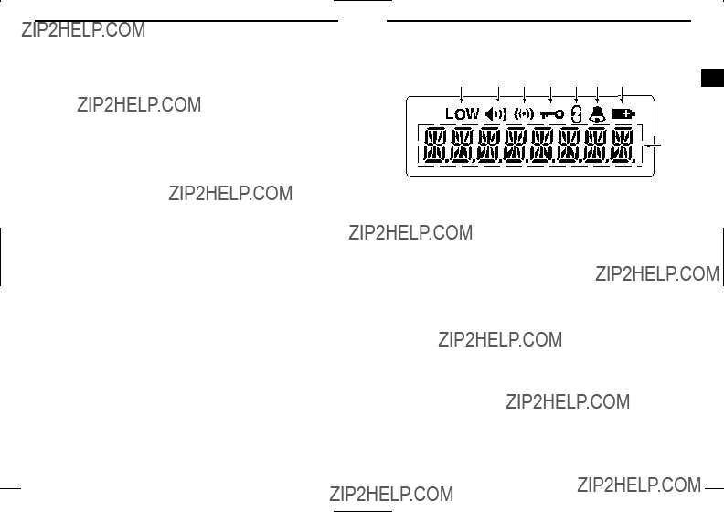
??? Function display
q OUTPUT POWER INDICATOR
Appears when Low 2 or Low 1 is selected.
w AUDIBLE INDICATOR
???Appears when the channel is in the ???audible??? (unmute) condi- tion.
???Appears when the speci???ed
e COMPANDER INDICATOR
Appears when the compander function is activated.
r KEY LOCK INDICATOR
Appears during the key lock function ON.
t SCRAMBLER INDICATOR
Appears when the voice scrambler function is activated.
y BELL INDICATOR
Appears/blinks when the speci???c
u BATTERY INDICATOR
Appears or blinks when the battery power decreases to a speci- ???ed level.
i ALPHANUMERIC DISPLAY
Displays the operating channel number, channel names, Set mode contents, DTMF numbers, etc.

2 PANEL DESCRIPTION
??? Programmable function keys
The following functions can be assigned to [P0], [P1], [P2], [P3], [Red], [ ] and [
 ] programmable function keys.
Consult your Icom dealer or system operator for details concerning your transceivers programming.
If the programmable function names are bracketed in the following explanations, the speci???c switch used to activate the function de- pends on programming.
CH UP AND DOWN KEYS
???Select an operating channel.
???Select a transmit code channel after pushing the [TX Code CH Select] keys.
???Select a DTMF channel after pushing the [DTMF Autodial] key.
???Select a scan group after pushing and holding the [Scan A Start/Stop]/[Scan B Start/Stop] keys.
???Select a BIIS code, status number or SDM after pushing the [Digital] key.
BANK SELECT KEY
Push this key, then push [CH Up] or [CH Down] to select the de- sired bank.
SCAN START/STOP KEYS
???Push this key to start scanning; and push again to stop.
???Push and hold this key to indicate the scan group, then select the desired scan group using [CH Up]/[CH Down].
SCAN TAG KEY
Adds or deletes the selected channel to the scan group.
Select an operating channel directly.
MONITOR KEY
???Mute and release the CTCSS (DTCS) or
???Activates one of (or two of) the following functions on each chan- nel independently: (PMR or BIIS PMR operation only)
???Push and hold to
???Push to mute the channel (sets to ???Inaudible??? only).
???Push to
???Push after the communication is ???nished to send a ???reset code???.
NOTE: The
LOCK KEY
Push and hold to electronically lock all programmable keys except the following:
[Call] (incl. Call A and Call B), [Moni(Audi)] and [Emergency] keys.
OUTPUT POWER SELECTION KEY
Select the transmit output power temporarily or permanently, de- pending on the
??? Ask your dealer for the output power level for each selection.

2 PANEL DESCRIPTION
C.TONE CHANNEL ENTER KEY
Select the continuous tone channel using [CH Up]/[CH Down] keys to change the tone frequency/code setting after pushing this key for permanent operation.
TALK AROUND KEY
Turn the talk around function ON and OFF.
???The talk around function equalizes the transmit frequency to the re- ceive frequency for
WIDE/NARROW KEY
Push to toggle the IF bandwidth between wide and narrow.
???The wide passband width can be selected from 25.0 or 20.0 kHz using the
DTMF AUTODIAL KEY
???Push to enter the DTMF channel selection mode. Then select the desired DTMF channel using [CH Up]/[CH Down] keys.
???After selecting the desired DTMF channel, push this key to trans- mit the DTMF code.
DTMF
Push to transmit the
CALL KEYS
Push to transmit a
???Call transmission is necessary before you call another station de- pending on your signalling system.
???The [Call A] and/or [Call B] keys may be available when your system employs selective ???Individual/Group??? calls. Ask your dealer which call is assigned to each key.
PANEL DESCRIPTION 2
EMERGENCY KEYS
???Push and hold to transmit an emergency call.
???When [Emergency Single (Silent)] or [Emergency Repeat 2 (Silent)] is pushed, an emergency call is transmitted without a beep emission and LCD indication change.
???If you want to cancel the emergency call, push (or push and hold) the key again before transmitting the call.
???The emergency call is transmitted one time only or repeatedly until receiving a control code depending on the
TX CODE ENTER KEY (PMR or BIIS PMR operation only)
Push to enter the direct ID code edit mode, for both
TX CODE CHANNEL SELECT KEY
???Push to enter the direct ID code channel selection mode. Then set the desired channel using [CH Up]/[CH Down]/[TX Code CH Up]/[TX Code CH Down]. (p. 15)
???While in ID code channel selection mode, push for 1 sec. to enter the ID code edit mode for
TX CODE CHANNEL UP/DOWN KEYS
Push to select a TX code channel directly.
ID MEMORY READ KEY (PMR or BIIS PMR operation only)
???Recalls detected ID codes.
???Push this key, then push [CH Up]/[CH Down] for selection.
???Up to 5 ID???s are memorized.
???Push and hold to erase the selected memorized ID???s.

2 PANEL DESCRIPTION
VOICE SCRAMBLER FUNCTION
Push to toggle the voice scrambler function ON and OFF.
COMPANDER KEY
Push to toggle the compander function ON and OFF.
The compander function reduces noise components from the trans- mitting audio to provide clear communication.
USER SET MODE KEY
???Push and hold to enter user set mode.
???During user set mode, push this key to select an item, and push [CH Up]/[CH Down] to change the value or condition.
???Push and hold this key again to exit user set mode.
???User set mode is also available via the ???Power ON function???. Please refer to p. 18 also.
DIGITAL KEY (BIIS operation only)
???Push to select the call ID list, transmit message and standby condition. Toggles between queue channel and received mes- sage record indication after queue channel is selected.
???Push and hold to select queue channel indication.
STATUS UP/DOWN KEYS (BIIS operation only)
???While in the standby condition, push to display the transmit sta- tus indication and select a status number.
???When a received SDM is displayed, push to cancel the automatic scroll and scroll the message manually.
???When an SDM that contains more than 8 characters is displayed, push to scroll the message manually.
???The keys in the table below can be used for password input:
???The transceiver detects numbers in the same block as identical. Therefore ???01234??? and ???56789??? are the same.
eWhen the ???PASSWORD??? indication does not clear after inputting 4 digits, the input code number may be incorrect. Turn the power off and start over in this case.
??? Channel selection
Several types of channel selections are available. Methods may dif- fer according to your system set up.
Push [ ]/[
]/[ ] to select the desired operating channel, in se- quence; or, push one of the
Push [Bank], then push [ ] or [
 ] to select the desired bank.
AUTOMATIC SCAN TYPE:
Channel setting is not necessary for this type. When turning the power ON, the transceiver automatically starts scanning. Scanning stops when receiving a call.
3 CONVENTIONAL OPERATION
??? Call procedure
When your system employs tone signalling (excluding CTCSS and DTCS), the call procedure may be necessary prior to voice trans- mission. The tone signalling employed may be a selective calling system which allows you to call speci???c station(s) only and prevent unwanted stations from contacting you.
qSelect the desired TX code channel or
???This may not be necessary depending on programming.
???Refer to pgs. 15, 16 for selection.
wPush the call switch (assigned to one of the dealer programma- ble switches: [P0], [P1], [P2], [P3], [Red], [ ] and [
 ]).
]).
eAfter transmitting a
CONVENTIONAL OPERATION 3
??? Receiving and transmitting
eWhen receiving a call, adjust the audio output level to a comfort- able listening level.
Transmitting:
Wait for the channel to become clear to avoid interference.
q While pushing and holding [PTT], speak into the microphone at a normal voice level.
???When a tone signalling system is used, the call procedure de- scribed at left may be necessary.
wRelease [PTT] to return to receive.
IMPORTANT: To maximize the readability of your signal;
1.Pause brie???y after pushing [PTT].
2.Hold the microphone 5 to 10 cm (2 to 4 inches) from your mouth, then speak into the microphone at a normal voice level.

3 CONVENTIONAL OPERATION
D Transmitting notes
??? Transmit inhibit function
The transceiver has several inhibit functions which restrict trans- mission under the following conditions:
-The channel is in mute condition (???Inaudible??? condition; ???
 ??? does not appear).
-Channel is busy.
-
-The selected channel is a ???receive only??? channel.
???
After continuous transmission for the
??? Penalty timer
Once the
D TX code channel selection
If the transceiver has [TX Code CH Select] assigned to it, indica- tion can be toggled between the operating channel number (or name) and TX code channel number (or name). When the TX code channel number (or name) is displayed, the [ ]/[
]/[ ] key selects the TX code channel.
TO SELECT A TX CHANNEL:
q Push [TX Code CH Select]??? a TX code channel appears. w Push [ ]/[
]/[ ] to select the desired TX code channel.
ePush [Call] (or [PTT] during MSK operation) to transmit the se- lected TX code.
rPush [TX Code CH Select] again to return to the operating chan- nel number indication.
FOR TX CODE CHANNEL TYPE:
If the transceiver has a [TX Code CH Up] or [TX Code CH Down] key assignment, the programmed TX code channel can be selected directly.
CONVENTIONAL OPERATION 3
D TX code number edit (PMR or BIIS PMR operation only) If the transceiver has [TX Code CH Select] or [TX Code Enter] as- signed to it, TX code contents can be edited within the allowable
wPush [TX Code CH Select] for 1 sec. to enter the TX code edit mode.
e Push [TX Code CH Select] to select the desired digit to be edited.
r Set the desired digit using [ ]/[
]/[ ]/[TX Code CH Up]/[TX Code CH Down].
tPush [TX Code CH Select] to set the digit. The editable digit will move to the right automatically.
y Repeat r and t to input all allowable digits.
u Push [Call] or [PTT] to transmit the selected TX code.
TO EDIT A TX CODE VIA [TX CODE ENTER] KEY:
qSelect the desired TX code channel via [TX Code CH Up]/[TX Code CH Down].
w Push [TX Code Enter] to enter the TX code edit mode.
e Push [TX Code Enter] to select the desired digit to be edited.
rSet the desired digit using [ ]/[
]/[ ]/[TX Code CH Up]/[TX Code CH Down].
t Push [TX Code Enter] to set the digit. The editable digit will move to the right automatically.
y Repeat r and t to input all allowable digits.
u Push [Call] or [PTT] to transmit the selected TX code.

3 CONVENTIONAL OPERATION
D DTMF transmission
If the transceiver has [DTMF Autodial] assigned to it, the automatic DTMF transmission function is available. Up to 8 DTMF channels are available.
TO SELECT A TX CODE:
q Push [DTMF Autodial]??? a DTMF channel appears. w Push [ ]/[
]/[ ] to select the desired DTMF channel.
ePush [DTMF Autodial] to transmit the DTMF code in the selected DTMF channel.
??? Scrambler function
The voice scrambler function provides private communication be- tween stations. The frequency inversion type is equipped to all ver- sions, and some versions have the Rolling or
q Push [Scrambler] to turn the scrambler function ON. w ???  ??? appears.
e Push [Scrambler] again to turn the scrambler function OFF.
CONVENTIONAL OPERATION 3
??? User set mode
User set mode is accessed at power ON and allows you to set
Entering the user set mode:
q While pushing and holding [ ] and [
 ], rotate [VOL] to enter the user set mode at power ON.
wPush and hold [P0] to enter user set mode. Push [P0] momen- tarily to select the item.
Then push [ ] and [
 ] to set the desired level/condition.
Available set mode functions:
??? Battery Voltage : ON or OFF
e Push and hold [P0] again to exit set mode.
User set mode is also available using a programmable key. Please refer to p. 11 [User Set Mode] section.

4 BIIS OPERATION
??? Default setting
The following functions are assigned to each programmable switch as the default. Ask your dealer for details.
[ ]/[
]/[ ]; CH Down/Up
:While in the standby condition, selects the operating channel.
BIIS OPERATION 4
??? Receiving a call
D Individual call
qWhen an individual call is received;
??? Beeps sound.
???The programmed text message (e.g.???


 ???) and the calling station ID (or text) is displayed alternately, depending on the set- ting.
??????  ??? appears or blinks depending on the setting.
w Push and hold [PTT], then speak into the microphone at a nor- mal voice level.
???Transmit/Busy indicator lights red. e Release [PTT] to return to receive.
???Transmit/Busy indicator lights green while receiving a signal.
r To finish the conversation, push [P3] (Moni(Audi)) to send the ???Clear down??? signal.
??? Either station can send a clear down signal.
??? ??? 


 ??? is displayed for 2 sec. (approx.).
?????? 
 ??? disappears and the transceiver returns to the standby condi- tion.

4 BIIS OPERATION
D Group call
qWhen a group call is received;
???Beeps sound.
?????? 
 ??? appears and the mute is released.
???The programmed text message (e.g.??? 


 ???) and the calling sta- tion ID (or text) is displayed alternately, depending on the setting.
??????  ??? appears or blinks depending on the setting.
wPush and hold [PTT], then speak into the microphone at a nor- mal voice level.
NOTE: Only one station is permitted to speak.
???Transmit/Busy indicator lights red. e Release [PTT] to return to receive.
???Transmit/Busy indicator lights green while receiving a signal.
r To finish the conversation, push [P3] (Moni(Audi)) to send the ???Clear down??? signal.
??? Either station can send a clear down signal.
??? ??? 


 ??? is displayed for 2 sec. (approx.)
?????? 
 ??? disappears and the transceiver returns to the standby condi- tion.
BIIS OPERATION 4
DDisplaying the received call record
??? Queue indication
The transceiver memorizes the calling station IDs for record. Up to 3 calls can be memorized, and the oldest call record is erased
when a 4th call is received. However, once the transceiver is pow- 4 ered OFF, the all records are cleared.
qPush [P1] (Digital) for 1 sec.
??? Displays following indication.
When a record is available
When no record is available
w Push [ ]/[
]/[ ] to select the desired call.
ePush [P1] (Digital) for 1 sec. again to return to the standby con- dition.
???When no operation is performed for 30 sec., the transceiver returns to the standby condition automatically.

4 BIIS OPERATION
??? Transmitting a call
Total of a 3 ways for code selection are
D Using call memory
qWhile in the standby condition, push [P1] (Digital) to enter the call code memory channel selection mode.
Call code text is displayed.
w Push [ ]/[
]/[ ] to select the desired call code.
ePush [P0] (Call) or [PTT]* to call.
*PTT call can be made only when PTT call capability is permitted.
NOTE: When no answer back is received, the transceiver re- peats the call 3 times (default) automatically, and ??? 


 ??? is displayed during each call. However, an error beep sounds and ???


 ??? is displayed when no answer back is received after the calls.
r Push [PTT] to transmit; release to receive.
t Push [P3] (Moni(Audi)) to send the ???Clear down??? signal.
BIIS OPERATION 4
D Calling back from the queue channel
qWhile in the standby condition, push [P1] (Digital) for 1 sec. to enter queue memory channel selection mode.
ePush [P0] (Call) or [PTT]* to call.
*PTT call can be made only when PTT call capability is permitted.
NOTE: When no answer back is received, the transceiver re- peats the call 3 times (default) automatically, and ??? 


 ??? is displayed during each call. However, an error beep sounds and ???


 ??? is displayed when no answer back is received after the calls.
r Push [PTT] to transmit; release to receive.
t Push [P3] (Moni(Audi)) to send the ???Clear down??? signal.

4 BIIS OPERATION
D Direct code entry
qWhile in the standby condition, push [TX Code Enter] to enter the TX code edit mode.
??? Editable code digit blinks.
wPush [TX Code Enter] to select the desired digit to be edited.
??? Editable digit differs according to the setting.
e Set the desired digit using [ ]/[
]/[ ]/[TX Code CH Up]/[TX Code CH Down].
r Push [TX Code Enter] to set the digit. The editable digit will move to the right automatically.
t Repeat e and r to input all allowable digits.
yPush [P0] (Call) or [PTT]* to call.
*PTT call can be made only when PTT call capability is permitted.
NOTE: When no answer back is received, the transceiver re- peats the call 3 times (default) automatically, and ???


 ??? is displayed during each call. However, an error beep sounds and ???


 ??? is displayed when no answer back is received after the calls.
u Push [PTT] to transmit; release to receive.
i Push [P3] (Moni(Audi)) to send the ???Clear down??? signal.
For your information
When the ???UpDate??? setting for the call code is enabled, the set code is overwritten into the call code memory.
BIIS OPERATION 4
??? Receiving a message
D Receiving a status message
qWhen a status message is received;
??? Beeps sound.
??? The calling station ID (or text) and the status message is displayed 4 alternately, depending on the setting.
w Push [P3] (Moni(Audi)) to return to the standby condition.
NOTE: Only the calling station ID (or text) is displayed (no message is displayed alternately) when the scroll timer is set to ???OFF???. In this case, push [Status Up]/[Status Down] to dis- play the status message manually.
4 BIIS OPERATION
D Receiving an SDM
qWhen an SDM is received;
???Beeps sound.
???The calling station ID (or text) and the SDM is displayed alternately, depending on the setting.
wWhen the received SDM includes more than 8 characters, the message scrolls automatically, when the automatic scroll func- tion is activated.
???Push [Status Up]/[Status Down] to scroll the message manually. e Push [P3] (Moni(Audi)) to return to the standby condition.
27
BIIS OPERATION 4
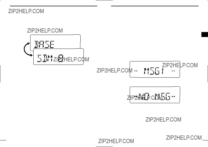
D Received message selection
The transceiver memorizes the received messages for record. Up
qPush [P1] (Digital) for 1 sec.
??? Displays queue memory.
wPush [P1] (Digital) momentarily.
??? Displays message memory.
When a message is available
When no message is available
ePush [ ]/[
]/[ ] to select the desired message.
???When selecting the SDM that includes more than 8 characters, the message scrolls automatically, when the automatic scroll function is activated.
???Push [Status Up]/[Status Down] to scroll the message manually. r Push [P1] (Digital) for 1 sec. again to return to the standby con-
dition.
???When no operation is performed for 30 sec., the transceiver returns to the standby condition automatically.
28
4 BIIS OPERATION
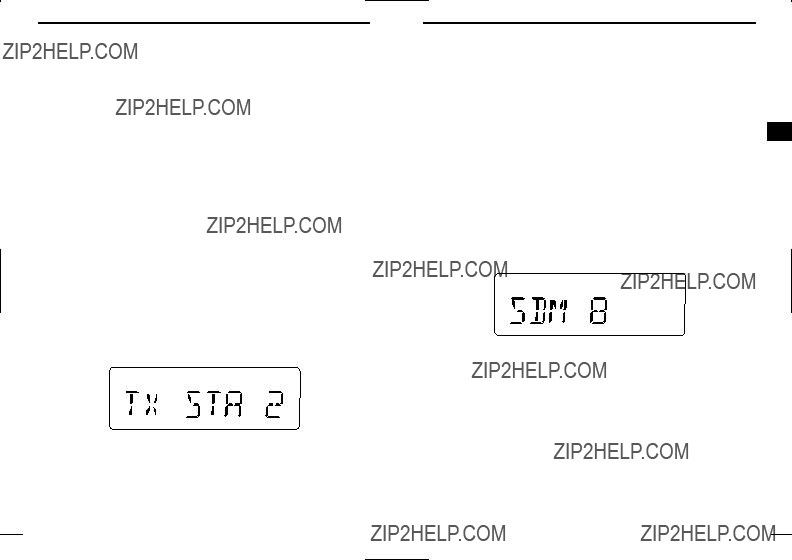
??? Transmitting a status
D General
The status message can be selected with the programmed text, and the message text is also displayed on the function display of the called station.
Up to 24 status types (1 to 24) are available, and the status mes- sages 22 and 24 have designated meanings.
Status 22: Emergency*
Status 24: GPS request
*The status 22 can also be used as a normal status message by dis- abling the designated meaning. However, the status 24 is ???xed.
The status call can be sent with both individual and group calls.
D Transmitting a status
qWhile in the standby condition, push [P1] (Digital), then push [ ]/[
]/[ ] to select the desired station/group code.
wPush [P1] (Digital) again, then push [ ]/[
]/[ ] to select the de- sired status message.
Or, you can select the desired status message using [Status Up]/[Status Down] key directly.
Status message is displayed.
ePush [P0] (Call) or [PTT]* to transmit the status message to the selected station/group.
*PTT call can be made only when PTT call capability is permitted.
???2 beeps will sound and the transceiver returns to the standby con- dition automatically when the transmission is successful.
29
BIIS OPERATION 4
??? Transmitting an SDM
D General
The short data message, SDM, can be sent to an individual station
D Transmitting an SDM
qWhile in the standby condition, push [P1] (Digital), then push [ ]/[
]/[ ] to select the desired station/group code.
wPush [P1] (Digital) again, then push [ ]/[
]/[ ] to select the de- sired SDM.
Or, you can select the desired SDM using [Status Up]/[Status Down] key directly.
SDM is displayed.
ePush [P0] (Call) or [PTT]* to transmit the SDM to the selected station/group.
*PTT call can be made only when PTT call capability is permitted.
???2 beeps will sound and the transceiver returns to the standby con- dition automatically when the transmission is successful.
30

4 BIIS OPERATION
??? Position data transmission
When the optional
Ask your dealer or system operator for connection details.
The position data is transmitted when;
???Status 24 message is received
*When the status 24 message, GPS request, is received.
???Fully automatic
When automatic position transmission is enabled, send the po- sition data according to ???Time Marker??? and ???Interval Timer??? set- tings.
???PTT is released
When ???Send with Logoff??? is enabled.
- Set the
???After sending a status message When ???Send with Status??? is enabled.
???After sending an SDM
When ???Send with SDM??? is enabled.
???After sending status 22 (Emergency) When ???Send with Emergency??? is enabled.
BIIS OPERATION 4
??? Printer connection
??? PC connection
When the optional
Ask your dealer or system operator for connection details.
??? Digital ANI
The own ID can be transmitted each time the PTT is pushed
In addition, when using the ANI with
4 BIIS OPERATION
??? Auto emergency transmission
When [Emergency Single (Silent)] or [Emergency Repeat (Silent)] is pushed, an emergency signal is automatically transmitted for the speci???ed time period.
The status 22 (Emergency) is sent to the selected ID station, and the position data is transmitted after the emergency signal when a GPS receiver is connected to the transceiver.
The emergency transmission is performed on the emergency chan- nel, however, when no emergency channel is speci???ed, the signal is transmitted on the previously selected channel.
There is no change in the function display or beep emission during automatic emergency transmission.
??? Stun function
When the speci???ed ID, set as a killer ID, is received, the stun func-
BIIS OPERATION 4
??? BIIS indication
The following indications are available for the BIIS operation on an MSK channel.
: Individual/group call is successful.
: Message (status or SDM) transmission is successful.
: No answer back is received.
: Appears during retry of the call (2nd call).


 : End the communication.
: Operating channel is in the busy condition.
??? Priority A channel selection
When one of the following operations is performed, the transceiver selects the Priority A channel automatically.
Priority A is selected when;
4
tion is activated.
When the killer ID is received, the transceiver switches to the pass- code required condition. Entering of the passcode via the keypad is necessary to operate the transceiver again in this case.
???Clear down signal is received/transmitted
-Set the ???Move to PrioA CH??? item as ???Clear Down???.
???Turning the power ON
The Priority A channel is selected each time the transceiver power is turned ON.
???Status call
The Priority A channel is selected when transmitting a status call.
-Enable the ???Send Status on PrioA CH??? item in the MSK con- ???guration.

5 BATTERY CHARGING
??? Battery charging
Prior to using the transceiver for the ???rst time, the battery pack must be fully charged for optimum life and operation.
CAUTION: To avoid damage to the transceiver, turn it OFF while charging.
???Recommended temperature range for charging: +10??C to +40??C (+50??F to +104??F)
-The
???Use the specified chargers
???Use the optional AC adapter
???NEVER use another manufacturer???s AC adapter.
Recommendation:
Charge the supplied battery pack for a maximum of up to 10 hours.
BATTERY CHARGING 5
??? Caution
CAUTION! NEVER insert battery pack/transceiver (with the bat- tery pack attached) with wet or soiled into the charger. This may re- sult in corrosion of the charger terminals or damage to the charger. The charger is not waterproof and water can easily get into it.

5 BATTERY CHARGING
??? Optional battery chargers
?? Regular charging with the
q Attach the
wConnect the AC adapter
*Depending on version.
e Insert the battery pack with/without the transceiver into the charger.
??? The charge indicator lights green.
rCharge the battery pack approx.
Supplied screws
AC adapter
BATTERY CHARGING 5
D For your convenience
5
Eyelet
USE a rubber band to secure the transceiv- er while charging, if desired.

5 BATTERY CHARGING
??
qInstall the
Desktop charger adapter

 Connectors
Plugs
BATTERY CHARGING 5
wConnect the plugs of the

5 BATTERY CHARGING
D Rapid charging with the
The optional
The following are additionally required:
BATTERY CHARGING 5
D Rapid charging with the
The optional
???Six
???An AC adapter
AC adapter
(Not supplied with some versions.)
AC adapter (Purchase separately.)
5
Optional
DC power cable

5 BATTERY CHARGING
??? Optional battery case
When using the optional battery case attached to the transceiver, install 5 ??? AA (R6) size alkaline batteries as illustrated at right. The
qHook your ???nger under the latch, and open the cover in the direc- tion of the arrow (q). (Fig.1)
wThen, install 5 ??? AA (R6) size alkaline batteries. (Fig.2)
???Install the alkaline batteries only.
???Be sure to observe the correct polarity.
???Do not pin the ribbon under the batteries.
eClose the cover by ???tting in the direction of the arrow (w) ???rst, then check the latch is in place (e). (Fig.1)
???Be sure the gasket and the ribbon are set correctly, and do not pro- trude from the battery case. (Fig.3)
CAUTION:
???When installing batteries, make sure they are all the same brand, type and capacity. Also, do not mix new and old batter- ies together.
???Keep battery contacts clean. It???s a good idea to clean battery terminals once a week.
BATTERY CHARGING 5
q
5
w 

 e
e
Fig.2
Ribbon
Fig.3
Gasket
Ribbon
6
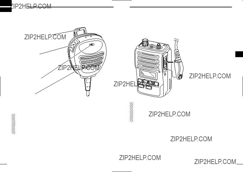
??? Optional
Alligator type clip
To attach the
PTT switch
Transmits while pushed
Receives while released
Microphone
Speaker
NEVER immerse the connector in water. If the connector becomes wet, be sure to dry it BEFORE attaching it to the transceiver.
NOTE: The microphone is located at the top of the
??? Attachment
Attach the connector of the
6
 CAUTION: Attach the
IMPORTANT: KEEP the [SP MIC] jack cover attached (trans- ceiver) when the

7 OPTIONS
???
Battery case for 5 ??? AA (R6) alkaline cells.
???
7.2V/1700 mAh
???
Used for regular charging of the battery pack. The AC adapter,
Charging time: approx.
???
For rapid charging of battery packs. An AC adapter is not supplied with some versions.
Charging time: approx. 2 to 2.5 hours
OPTIONS 7
???
For rapid charging of up to 6 battery packs (six
7
???
???
Provides advanced operation, such as printer, GPS connection for position data transmission capabilities during BIIS operation.
