HP StorageWorks
SAN Switch installation guide
Part number:
Fifth edition: May 2007
HP StorageWorks
SAN Switch installation guide
Part number:
Fifth edition: May 2007
Legal and notice information
??Copyright
??Copyright
the furnishing, performance, or use of this material.
This document contains proprietary information, which is protected by copyright. No part of this document may be photocopied, reproduced, or translated into another language without the prior written consent of
Compaq Computer Corporation is a

Contents
4
6
Supported HBAs . . . . . . . . . . . . . . . . . . . . . . . . . . . . . . . 145

Figures
8

Tables
10
About this guide
This installation guide provides information to help you set up and configure the following HP switches:
???HP StorageWorks 4/8 SAN Switch
???HP StorageWorks 4/16 SAN Switch
???HP StorageWorks SAN Switch 4/32
???HP StorageWorks 4/64 SAN Switch
???HP StorageWorks 4/32B SAN Switch
???About this Guide??? topics include:
???Intended audience, page 11
???Related documentation, page 11
???Document conventions and symbols, page 12
???HP technical support, page 13
Intended audience
This guide is intended for use by system administrators and technicians who are experienced with the following:
???Configuration aspects of customer Storage Area Network (SAN) fabric
???A customer host environment, such as Microsoft Windows or IBM AIX
???The
Related documentation
Access documents, including white papers and best practices documents from the
http://www.hp.com/go/san
 IMPORTANT:
For late breaking, supplemental information, access the latest version of the HP StorageWorks Fabric OS 5.2.x release notes.
Document conventions and symbols
This document follows the conventions in Table 1.
Table 1 Document conventions
 WARNING!
Text set off in this manner indicates that failure to follow directions in the warning could result in bodily harm or death.
 CAUTION:
Text set off in this manner indicates that failure to follow directions could result in damage to equipment or data.
 NOTE:
NOTE:
Text set off in this manner presents commentary, sidelights, or interesting points of information.

Rack stability
Rack stability protects personnel and equipment.
 WARNING!
To reduce the risk of personal injury or damage to the equipment, be sure that:
???The leveling jacks are extended to the floor.
???The full weight of the rack rests on the leveling jacks.
???In single rack installations, the stabilizing feet are attached to the rack.
???In multiple rack installations, the racks are coupled.
???Only one rack component is extended at any time. A rack may become unstable if more than one rack component is extended for any reason.
HP technical support
Telephone numbers for worldwide technical support are listed on the HP support web site:http://www.hp.com/support/.
Collect the following information before calling:
???Technical support registration number (if applicable)
???Product serial numbers
???Product model names and numbers
???Applicable error messages
???Operating system type and revision level
???Detailed, specific questions
For continuous quality improvement, calls may be recorded or monitored.
HP strongly recommends that customers sign up online using the Subscriber???s choice web site:
???Subscribing to this service provides you with
???After signing up, you can quickly locate your products by selecting Business support and then Storage under Product Category.
If you still have a question after reading this guide, contact an HP authorized service provider or access our Web site: http://www.hp.com.
HP authorized reseller
For the name of your nearest
???In the United States, call
???Elsewhere, visit the HP web site: http://www.hp.com. Then click Contact HP to find locations and telephone numbers.
Helpful web sites
For
???http://www.hp.com
???http://www.hp.com/go/storage
???http://www.hp.com/support/
???http://www.docs.hp.com

1 Overview
This chapter describes the following topics:
???4/8 and 4/16 SAN Switch models, page 15
???Enabling E_Ports on the 4/8 SAN Switch , page 18
???4/32 SAN Switch models, page 20
???4/64 SAN Switch models, page 24
???4/32B SAN Switch models, page 29
???SAN Switch ISL Trunking groups, page 31
???Optional SAN Switch features, page 32
???SAN Swtich optional kits, page 33
4/8 and 4/16 SAN Switch models
The HP StorageWorks 4/8 SAN Switch and 4/16 SAN Switch models include:
???HP StorageWorks 4/8 SAN Switch Base ships with eight ports activated and no E_Port license. It includes Advanced Web Tools and Zoning as standard software components.
???HP StorageWorks 4/8 SAN Switch Full ships with eight ports activated and includes a Full Fabric license, Advanced Web Tools, and Zoning as standard software components.
???HP StorageWorks 4/16 SAN Switch ships with 16 ports activated and includes a Full Fabric license, Advanced Web Tools, and Zoning as standard software components.
???HP StorageWorks 4/16 SAN Switch Power Pack ships with 16 ports activated and includes a Full Fabric license, Advanced Web Tools, and Zoning as standard software components. It also includes integrated licenses for all optional management tools (including Advanced Performance Monitoring, ISL Trunking, Extended Fabric and Fabric Watch).
4/8 and 4/16 SAN Switch features
The 4/8 and 4/16 SAN Switches support link speeds of 1, 2, and 4 Gb/s. The switch operates in a fabric that contains multiple switches or as the only switch in a fabric.
The 4/8 and 4/16 SAN Switches provide the following features:
???
???HP System/e Rack
???HP 10000 G2 Series Rack, HP 9000 Series Rack and HP 10000 Series Rack
???Eight or sixteen Fibre Channel (FC) ports with the following characteristics:
???Automatic negotiation to the highest common speed of all devices connected to the port
???Port interfaces compatible with short wave and long wave small form factor pluggable (SFP) transceivers
???Universal and
???Ports activated via licenses. The 4/8 SAN Switch can be upgraded to 12 or 16 licensed ports via HP StorageWorks
???One
???One 10/100 Mb/s Ethernet port with an
???One
???Three
???A
16Overview
4/8 and 4/16 SAN Switch chassis
This section describes the chassis front (port side) and rear (nonport side).
4/8 and 4/16 SAN Switch port side
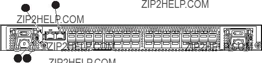
All LEDs reside on the port side of the switch (see Figure 1). The 4/8 and 4/16 SAN Switch enclosure uses
See Interpreting LED activity on page 69 for a complete description of switch LEDs.
scale: 5/16" = 1"
Figure 1 4/8 and 4/16 SAN Switch port side
4/8 and 4/16 SAN Switch nonport side
The nonport side is used solely for airflow and serial number labels. There are two labels on the rear of the chassis: one is the HP serial number, the other is the switch supplier???s serial number. The left label also contains the 4/8 SAN Switch or 4/16 SAN Switch MAC address and world wide name (WWN).
Activating additional 4/8 and 4/16 SAN Switch ports
The 4/16 SAN Switch models offer 8, 12, or 16 licensed ports. To enable ports 8 through 11, you must purchase and install one or more HP StorageWorks
To activate additional ports:
1.Use the portshow command to verify the number of ports licensed on your switch. The port status output indicates Started and Licensed for enabled ports. See the Fabric OS command reference manual for specific information on this command.
2.Use the switchshow command to obtain your SAN Switch WWN, which your HP representative requires to assign a license key.

3.Contact your HP representative to purchase the HP StorageWorks
4.Upon receipt of the HP StorageWorks
a.Log in to the 4/16 Switch as admin.
b.Issue the licenseadd command, followed by the license key enclosed in quotation marks. (The license key consists of approximately 16 uppercase and lowercase letters and numerals.)
 NOTE:
NOTE:
Enter the license key exactly as issued. If you enter the key incorrectly, the license will not function properly.
c.Issue the licenseshow command to verify that the license is valid. If a licensed product is not displayed, the license is invalid.
 NOTE:
NOTE:
It is not necessary to reboot the system. The product is available immediately after you enter the license key.
5.Configure the inactive ports. Issue the portstart command to start the ports. This command loads the port code, unlike the portenable command, which enables the port laser. For example:
portstart
6.Issue the portenable command to enable the ports. For example: portenable
7.Optional: Issue the portshow command to verify that the newly activated ports are started.
Enabling E_Ports on the 4/8 SAN Switch
The 4/8 SAN Switch requires that you purchase the Full Fabric Upgrade License, part number T4261A, to enable E_Ports (the 4/16 SAN Switch ships with the Full Fabric license installed). The switch, by default, cannot be connected to another switch until this license is installed. Without the license, the switch can still be directly connected to hosts and storage devices. To install the Full Fabric Upgrade License, use the licenseadd command. After it has been installed, the license appears under the licenseshow command as Full Fabric License and indicates that E_Ports are now automatically enabled when interswitch links (ISLs) are connected.
18Overview

SAN Switch licensing
SAN Switches operate differently in the network, depending on which HP StorageWorks domain licenses are installed. The 4/8 Base SAN Switch has no E_Port, unless you purchase and install the HP StorageWorks 4/8 Full Fabric Upgrade License.
???Full Fabric license??? Allows one or more switches to operate within a domain. All SAN Switch Power Pack models ship with this license installed.
To determine the type of license installed on your SAN Switch, issue the licenseshow command at the command line interface (CLI) prompt. The Full Fabric license is listed as Fabric license. A list of all licenses currently installed on the switch is displayed, as shown in Example 1.
Example 1:
switch:admin> licenseshow AbbbcDefcQxdezdr:
Web license Zoning license Fabric license
Remote switch license Extended fabric license Fabric Watch license Performance Monitor license Trunking license
Security license switch:admin>
 NOTE:
NOTE:
If the licensed feature is displayed, the feature is installed and immediately available.

4/32 SAN Switch models
The HP StorageWorks 4/32 SAN Switch models include:
???HP StorageWorks 4/32 SAN Switch Base ships with 16 ports activated and includes Zoning and Advanced Web Tools as standard software components.
???HP StorageWorks 4/32 SAN Switch Full ships with 32 ports activated and includes Zoning and Advanced Web Tools as standard software components.
???HP StorageWorks 4/32 SAN Switch Power Pack ships with 32 ports activated and includes a Full Fabric license, Advanced Web Tools, and Zoning as standard software components. It also includes integrated licenses for all optional management tools (including Advanced Performance Monitoring, ISL Trunking, Extended Fabric and Fabric Watch).
 NOTE:
NOTE:
To add ports, see Activating additional 4/32 SAN Switch ports on page 31.
4/32 SAN Switch features
The HP StorageWorks 4/32 SAN Switch provides the following features:
???
???
???Automatic negotiation to the highest common speed of all devices connected to the port
???Port interfaces compatible with SFP transceivers, both SWL and LWL
???Universal and
???One
???One 10/100 Mb/s Ethernet port with an
???Two redundant,
???Three redundant,
4/32 SAN Switch chassis
This section provides an illustration of the front (port side) and rear (nonport side) panels of the SAN Switch chassis and identifies the components of each side.
20Overview
4/32 SAN Switch port side
Figure 2 shows the port side of the 4/32 SAN Switch and identifies the components.
!IOIOI
LNK
SPD
1
scale: 1/8" = 1"
MRO25009a
scale: 5/16" = 1"
7. FC ports
Figure 2 4/32 SAN Switch port side
4/32 SAN Switch nonport side
Figure 3 shows the nonport side of the 4/32 SAN Switch, which contains the power supplies (including the AC power inlet and AC power switch) and fans.
Scale: 1/8" = 1"
MRO25010a
Figure 3 4/32 SAN Switch nonport side
Activating additional 4/32 and 4/32B SAN Switch ports
The SAN Switch 4/32 and 4/32B SAN Switches are available with either 16 ports (0 through 15) activated for the Base model or 32 ports (0 through 31) activated for the Full model.
To activate additional ports, contact your HP representative to purchase the HP StorageWorks
22Overview

 NOTE:
NOTE:
Check the port status to determine whether the license is preinstalled. Use the portshow command for ports 16 through 31. If the port status output indicates Started and Licensed, all 32 ports are activated.
1.If ports 16 through 31 show no license, you can purchase the HP StorageWorks
Your HP representative requires the 4/32 SAN Switch???s WWN in order to assign a license key. Enter the switchshow command to obtain the WWN of your 4/32 SAN Switch.
2.Install the HP StorageWorks
a.Log in to the 4/32 SAN Switch as admin.
b.Enter the licenseadd command, followed by the license key enclosed in quotation marks.
 NOTE:
NOTE:
Enter the license key exactly as issued. If you enter it incorrectly, the license will not function properly.
c.After entering the license key, use the licenseshow command to verify that the license is valid. If a licensed product is not displayed, the license is invalid.
 NOTE:
NOTE:
After entering a license key, the licensed product is available immediately. The system does not require a reboot.
3.Configure the inactive ports. Issue the portstart command to start the ports. This command loads the port code, unlike the portenable command, which enables the port laser. For example:
portstart
4.Issue the portenable command to enable the ports. For example: portenable
5.Optional: Issue the portshow command to verify that the newly activated ports are started.

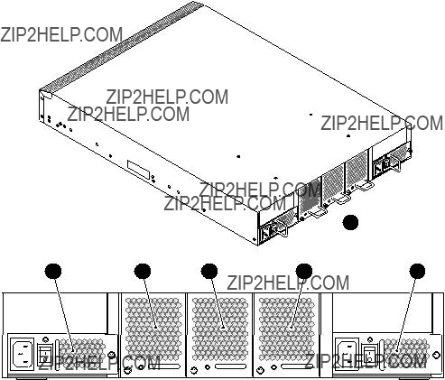
4/64 SAN Switch models
The HP StorageWorks 4/64 SAN Switch models include:
???HP StorageWorks 4/64 SAN Switch Base ships with 32 ports activated and includes Zoning and Advanced Web Tools as standard software components.
???HP StorageWorks 4/64 SAN Switch Full ships with 64 ports activated and includes Zoning and Advanced Web Tools as standard software components.
???HP StorageWorks 4/64 SAN Switch Power Pack ships with 32 ports activated and includes a Full Fabric license, Advanced Web Tools, and Zoning as standard software components. It also includes integrated licenses for all optional management tools (including Advanced Performance Monitoring, ISL Trunking, Extended Fabric and Fabric Watch).
 NOTE:
NOTE:
To add ports, see Activating additional 4/64 SAN Switch ports on page 28.
4/64 SAN Switch features
The HP StorageWorks 4/64 SAN Switch provides the following features:
???
???64 autosensing 1, 2, or
???Automatic negotiation to the highest common speed of all devices connected to the port
???Port interfaces compatible with SFP transceivers, both SWL and LWL
???Universal and
???Three redundant,
???Two redundant,
???Two AC power supply cables
???One
???One 10/100 Mb/s Ethernet port with an
???Three internal temperature sensors.
24Overview
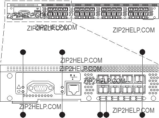
4/64 SAN Switch chassis
This section provides an illustration of the front (port side) and rear (nonport side) of the SAN Switch chassis.
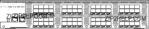
4/64 SAN Switch port side
Figure 4 shows the port side and identifies the components.
Figure 4 4/64 SAN Switch port side
26Overview
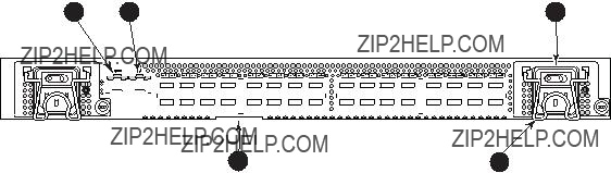
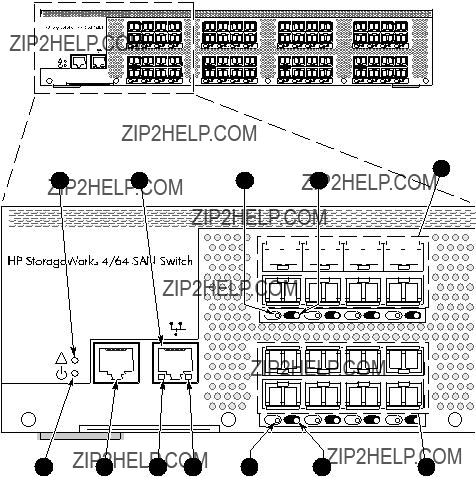
4/64 SAN Switch port numbering
Figure 5 identifies port numbering for the 4/64 SAN Switch.
Figure 5 4/64 SAN Switch port numbering
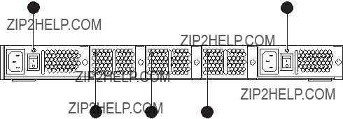
4/64 SAN Switch nonport side
Figure 6 shows the nonport side of the 4/64 SAN Switch, which contains the power supplies (including the AC power inlet and AC power switch) and fans.
1
25182a
Figure 6 4/64 SAN Switch nonport side
Activating additional 4/64 SAN Switch ports
The 4/64 SAN Switch contains 64 ports, with ports 0 through 31 enabled. To enable additional ports, you must purchase and install the HP StorageWorks
For example, to enable ports 32 through 47, you must purchase and install one HP StorageWorks
For detailed information on these optional licenses, see the Fabric OS administrator???s guide.
28Overview

4/32B SAN Switch models
The HP StorageWorks 4/32B SAN Switch models include:
???HP StorageWorks 4/32B SAN Switch ships with 16 ports activated, and includes a Full Fabric license, Zoning and Advanced Web Tools as standard software components.
???HP StorageWorks 4/32B Full SAN Switch ships with 32 ports activated, Full Fabric and includes Zoning and Advanced Web Tools as standard software components.
???HP StorageWorks 4/32B SAN Switch Power Pack ships with 32 ports activated, includes a Full Fabric license, Advanced Web Tools, and Zoning as standard software components. It also includes integrated licenses for all optional management tools (including Advanced Performance Monitoring, ISL Trunking, Extended Fabric and Fabric Watch).
 NOTE:
NOTE:
To add ports, see Activating additional 4/32 and 4/32B SAN Switch ports.
4/32B SAN Switch features
The HP StorageWorks 4/32B SAN Switch provides the following features:
???
???
???Automatic negotiation to the highest common speed of all devices connected to the port
???Port interfaces compatible with SFP transceivers, both SWL and LWL
???Universal and
???One
???One 10/100 Mb/s Ethernet port with an
???Two
4/32B SAN Switch chassis
This section provides an illustration of the front (port side) chassis and identifies the components.
4/32B SAN Switch port side
Figure 7 shows the port side of the 4/32B SAN Switch and identifies components.
Figure 7 4/32B SAN Switch port side
30Overview
Locating 4/32B SAN Switch FC ports
FC ports are numbered from left to right, in
25273a
Figure 8 4/32B SAN Switch FC ports
Activating additional 4/32B SAN Switch ports
The 4/32B SAN Switch is available with either 16 ports (0 through 15) activated for the standard model or 32 ports (0 through 31) activated for the Full or Power Pack models.
To activate additional ports, contact your HP representative to purchase the HP StorageWorks
 NOTE:
NOTE:
Check the port status to determine whether the license is preinstalled. Use the portshow command for ports 16 through 31. If the port status output indicates Started and Licensed, all 32 ports are activated.
See Activating additional 4/32 and 4/32B SAN Switch ports, page 22 for steps on installing the license and activating ports.
SAN Switch ISL Trunking groups
ISL Trunking is optional HP StorageWorks software that allows you to create trunking groups of ISLs between adjacent switches. For more information about trunking, see the
Fabric OS administrator???s guide.
If your SAN Switch is licensed for ISL Trunking (for example, Power Pack models ship with this license), use the trunking groups available on the switch.

 NOTE:
NOTE:
The maximum number of ports per trunk for the 4/8 and 4/16 SAN Switches is four.
The FC ports are numbered from left to right in groups of four. This arrangement indicates the groups of ports that can be used in the same ISL trunking group. The trunking groups are the two or four sets of ports at the top or bottom of the group, as shown in Figure 5 on page 27.
Optional SAN Switch features
SAN Switches support the following optional software, activated with the purchase of a license key:
 NOTE:
NOTE:
All SAN Switch Power Pack models ship with these licensed options enabled.
???ISL Trunking
???Secure Fabric OS
???Fabric Watch
???Advanced Performance Monitoring
???Extended Fabrics
For detailed information on these features, see the Fabric OS administrator???s guide for the firmware version you are running.
32Overview
SAN Switch optional port licenses and hardware
Table 2 lists the optional port licenses and hardware kits available for SAN Switches.
Table 2 Optional port licenses and hardware kits

 NOTE:
NOTE:
To obtain the latest information on hardware and software com- ponents, go to the
34Overview
2 Installing and configuring SAN Switches
This chapter describes the following topics:
???Shipping carton contents, page 35
???Installation and safety considerations, page 38
???Installing the switch as a
???Installing the switch using the SAN Switch Rack Mount Kit, page 41
???Cabling and configuring the SAN Switch, page 52
???Connecting the SAN Switch to the fabric, page 53
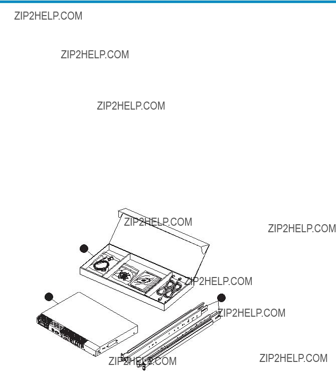
Shipping carton contents
Figure 9 and Table 3 identify shipping carton contents for a typical SAN Switch.
1
MRO25011b
Figure 9 SAN Switch shipping carton contents

Table 3 identifies the carton contents included with your SAN Switch.
Table 3 SAN Switch shipping carton checklist
Number Description
1One SAN Switch Accessories Box containing:
???One 3.0 m (10 ft)
???Plenum (not shown) ??? An air duct that attaches to the switch rails, enabling the switch to draw cooler air into the switch from outside the rack, rather than drawing in heated air from within the rack. SAN Switches that require a plenum include:
???SAN Switch 2/16V
???SAN Switch 2/16
???4/8 SAN Switch
???4/16 SAN Switch
???4/32B SAN Switch
???SAN Switch Rack Mount Kit hardware contained in plastic pouches:
??? 14
??? 14
??? Ten
??? Eight #10 alignment washers
??? Eight #10 adapter washers
??? Two
??? Two
??? Four rubber feet for mounting on a flat surface (a lab bench, for example)
???EZSwitchSetup CD
???One set of HP StorageWorks product documentation including Safety Guides, User License, Read Me First, and Warranty
???For the 4/8 and 4/16 SAN Switches, one
3One of the following:
??? One HP StorageWorks 4/8 SAN Switch
Installation and safety considerations
Install the switch using one of the following methods:
???As a
???HP highly recommends mounting the switch in one of the following HP customized racks:
???HP System/e Rack
???HP 10000 G2 Series Rack, HP 9000 Series Rack and HP 10000 Series Rack
See Installing the switch using the SAN Switch Rack Mount Kit on page 41 for detailed instructions.
Electrical considerations
For successful installation and operation of the switch, ensure that the following electrical requirements are met. For power supply information, see SAN Switch technical specifications on page 131.
???Primary AC input
???A correctly wired primary outlet, with a circuit protected by a circuit breaker and grounded in accordance with local electrical codes
???Adequate supply circuit, line fusing, and wire size, as specified by the electrical rating on the switch nameplate
Environmental considerations
Before installing the switch:
???To ensure adequate cooling, install the switch with the nonport side (which contains the air intake vents) facing the
???Verify that a minimum of 24 cubic ft/minute of airflow is available to the air intake vents on the nonport side of the switch.
???Verify that the ambient air temperature does not exceed 40 ??C (104 ??F) while the switch is operating.

 IMPORTANT:
The 40 ??C value applies to the ambient air temperature at the air intake vents on the nonport side of the switch. The temperature inside the switch can be up to 80 ??C (176 ??F) during switch operation. If the internal temperature range exceeds the operating ranges of the components, the LEDs, error messages, and Fabric Watch alerts indicate a problem. Enter the tempshow or Fabric Watch command to view temperature status.
 NOTE:
NOTE:
For a complete list of environmental considerations, see Table 25 on page 136.
Rack specifications
If you are installing the switch in a rack:
???Plan a rack space that is one rack unit (4.45 cm or 1.75 in) high, 48.3 cm (19 in) wide, and at least 76.2 cm (30 in) deep.
???Verify that the rack is mechanically secured to ensure stability in the event of an earthquake or other natural disaster.
???Ground all equipment in the rack through a reliable branch circuit connection; maintain the ground at all times. Do not rely on a secondary connection to a branch circuit, such as a power strip.
???Ensure that airflow and temperature requirements are met on an ongoing basis, especially if the switch is installed in a closed or
???Verify that the additional weight of the switch does not exceed the rack???s weight limits or unbalance the rack in any way.
Cooling considerations
Cooling air is drawn into the switch chassis by the fans mounted on the rear of the chassis. The air is expelled through vents in the front (port side) of the chassis. HP recommends installing the switch so that air intake and exhaust for all components in the rack are flowing in the same
Follow these guidelines to ensure proper airflow and to prevent component overheating:
???Install the switch with the nonport side (which contains the air intake vents) facing the
???Ensure that all equipment in the rack forces air in the same direction to avoid taking in exhaust air.
???Ensure that a minimum of 24 cu ft/min of airflow is available to the air intake vents on the nonport side of the switch.
???Ensure that the ambient air temperature does not exceed 40 ??C (104 ??F) while the switch is operating.
 NOTE:
NOTE:
Do not block air vents. The switch uses ambient air for cooling.
Installing the switch as a
To install the switch as a
1.Unpack the switch and verify that all items listed in Shipping carton contents on page 35 are present.
2.Locate the four rubber feet in the accessory box.
3.Apply the adhesive rubber feet to the switch. The rubber feet help prevent the switch from sliding off the supporting surface:
a.Clean the indentations at each corner of the bottom of the switch to ensure that they are free of dust or other debris that might lessen the adhesion of the feet.
b.With the adhesive side against the chassis, place one rubber foot in each indentation and press into place.
4.Place the switch on a flat, sturdy surface.
5.Apply power to the switch as described in Powering on and off on page 66.
 CAUTION:
Do not connect the switch to the network until the IP address is set. For instructions on setting the IP address, see Cabling and configuring the SAN Switch on page 52.
Installing the switch using the SAN Switch Rack Mount Kit
This section provides instructions for installing the SAN Switch in the following HP custom racks:
???HP System/e Rack
???HP 10000 G2 Series rack, HP 9000 and HP 10000 Series racks
For optimal cable management, HP recommends that you install the SAN Switch Rack Mount Kit to allow the nonport side of the switch to slide out of the
 NOTE:
NOTE:
The SAN Switch Rack Mount Kit installation requires one technician.
Obtain the following items:
???SAN Switch
???Power cables
???#2 Phillips screwdriver
???
???Plenum (if required, see Table 3) to determine if you need to install a plenum prior to rack mounting your switch).
???SAN Switch Rack Mount Kit hardware, shown in Table 4 on page 42, which identifies rails and rail mounting hardware
Table 4 SAN Switch Rack Mount Kit hardware
ItemDescription
Two rear mounting brackets
A right inner rail and a right outer rail
A left inner rail and a left outer rail
14
14
Ten
Eight #10 alignment washers
Eight #10 adapter washers
Two
Two
 CAUTION:
For proper airflow, the SFP media side of the SAN Switch must face the rear of the rack.
To install the switch in a rack:
1.Verify that the required parts and hardware are available. See Table 3 on page 36.
2.Choose a mounting location for the switch in the rack.
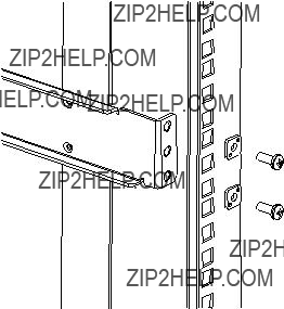
3.Attach the rear mounting brackets to the rear rack uprights:
???For HP 10000 series racks, assemble each of the two brackets with two
???For an HP System/e Rack, install the two rear mounting brackets with two
Figure 10 Installing the rear mounting brackets (HP 10000 series racks)
Figure 11 Installing the rear mounting brackets (HP System/e Rack)
 NOTE:
NOTE:
Your SAN Switch Rack Mount Kit contains both left rails and right rails.
4.Assemble the outer rails by completing option a or option b:
a.Attach the left outer rail and the right outer rail to the rear mounting brackets using two
Figure 12 Installing the outer rails (HP 10000 series racks)
b.Depending on the rack you are using, complete one of the following tasks:
???For HP 10000 series racks, install two
Figure 13 Assembling the outer rails (HP 10000 series racks)
???For an HP System/e Rack, install two
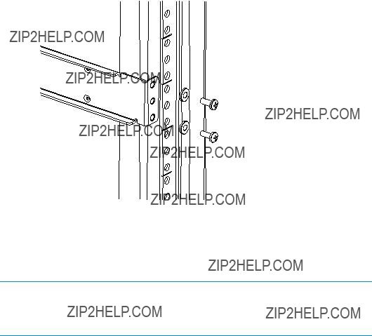
Figure 14 Assembling the outer rails (HP System/e Rack)
5.Depending on the device model, the SAN Switch Rack Mount Kit requires different screw types for securing the inner rails. Use Table 5 to determine the number and screw type for your specific switch.
 CAUTION:
Do not use any screws other than those provided. Using longer screws than those provided can cause damage to internal components.
Table 5 Number of screws required to assemble the inner rails

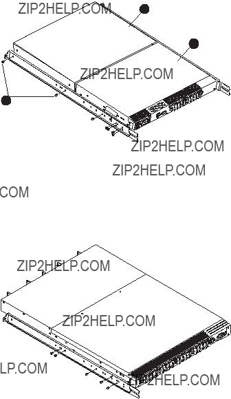
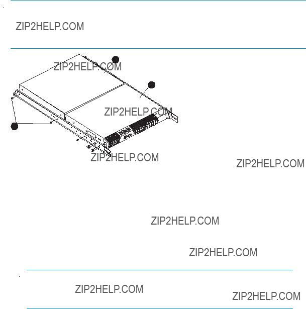
6.Identify the screw holes to be used on the inner rails designed for the switch:
???To attach the inner rails to the SAN Switch 2/32 use the screw holes marked 32.
???To attach the inner rails to the 4/8, /16 and 4/32B SAN Switches, use five screw holes marked 8, and the plenum requires one screw hole marked 8 and one screw hole marked 16, as shown in Figure 15 on page 48.
???To attach the inner rails to the 4/32 or 4/64 SAN Switch, use the screw holes marked 16, as shown in Figure 16 on page 48.
7.Assemble the two inner rails to the device using the appropriate number of screws (see Table 5):
???For the 4/8 and 4/16 SAN Switches, secure each inner rail (one on each side) to the switch using seven
???For the 4/32 SAN Switch, secure each inner rail (one on each side) to the switch using five
???For the 4/64 SAN Switch, secure each inner rail (one on each side) to the switch using five
???For the 4/32B SAN Switch, secure each inner rail (one on each side) to the switch using six
 NOTE:
NOTE:
For integration in a cabinet, tighten the
8.If you are installing the 4/8, 4/16 or 4/32B SAN Switch, verify that a plenum (an air duct that attaches to the switch rails, enabling the switch to draw cooler air into the switch from outside the rack, rather than drawing in heated air from within the rack.) is preinstalled, as shown in Figure 15.
If not installed, see Installing the Plenum (if required), page 49 to install a plenum on the 4/8, 4/16 or 4/32B SAN Switch.
If not installing one of the devices listed in step 8, go to Securing the switch to the outer rails, page 50 to complete the rack mount procedure.
1
2
3
25052a
Figure 15 Attaching the inner rails to the 4/8 or 4/16 SAN Switch
IOIOI
LNK
SPD
!
MRO25018b
Figure 16 Attaching the inner rails to the 4/32 or 4/64 SAN Switch

Installing the Plenum (if required)
If installing one of the following SAN switches only, you must install the plenum that ships in the accessory kit with the rack mount hardware:
???4/8 SAN Switch
???4/16 SAN Switch
???4/32B SAN Switch
To install the plenum:
1.Place the device (with inner rails attached) on a flat surface, see Figure 17.
2.Obtain the plenum and four
3.For each inner rail (Left and Right) use one screw hole marked 8 and one screw hole marked 16 to attach the plenum.
 CAUTION:
Verify that the open end of the plenum faces the rear of the switch. For example, when installed properly you should see the plenum???s air vent holes on one side, and the front panel of the switch on the other.
 NOTE:
NOTE:
Figure 17 illustrates how to attach the plenum to the 4/8 or 4/16 SAN Switch specifically. If installing the plenum on the 4/32B SAN Switch, the procedure and figure also applies.
3
1
2
OII OI
25052a
Figure 17 Attaching the Plenum to the 4/8 or 4/16 SAN Switch
Securing the switch to the outer rails
To secure the switch to the outer rails:
1. Insert the switch with the attached inner rails into the outer rails.
 NOTE:
NOTE:
This step applies to installing a switch in HP 9000 Series, HP 10000
Series or HP System/e racks.
2.Insert the device into the rack and install (2)
Figure 18 Securing the switch (in HP 9000 Series or HP 10000 Series Racks)
Figure 19 Securing the switch (in an HP System/e rack)
3. Tighten the hex nuts installed earlier. See step 4a, page 44.
 NOTE:
NOTE:
To uninstall a switch, remove the middle
This completes the rack mount procedure.

Cabling and configuring the SAN Switch
The SAN Switch must be configured to ensure correct operation with a network and fabric. For instructions on configuring the switch to operate in a fabric containing switches from other vendors, see the Fabric OS administrator???s guide.
For more information about the commands used in this procedure, see the Fabric OS command reference manual for the Fabric OS version running on your switch.
 NOTE:
NOTE:
All supporting Fabric OS documentation is accessible from the
Recommendations for cable management
Before installing the switch, plan the rack space required for cable management based on the following HP recommendations:
???Leave enough space to allow for the fact that the minimum bend radius for a
???Leave at least 1 m (3.28 ft) of slack for each port cable. This provides room to remove and replace the switch, allows for inadvertent movement of the rack, and helps prevent the cables from being bent to less than the minimum bend radius.
???If you are using ISL Trunking, consider grouping cables by trunking groups. The cables used in trunking groups must meet specific requirements, as described in the Fabric OS administrator???s guide.
???For easier maintenance, label the fiber optic cables and record the devices to which they are connected.
???Keep LEDs visible by routing port cables and other cables away from the LEDs.
???Do not use tie wraps on fiber optic cables; tie wraps are easily overtightened and can damage the optic fibers. HP recommends using velcro straps to secure and organize fiber optic cables.
Connecting the SAN Switch to the fabric
Connecting the SAN Switch to the fabric involves the following steps:
1.Obtain required items on page 53
2.Make a serial connection on page 53
3.Apply power to the switch and log in on page 56
4.Set the IP address on page 57
5.Create an Ethernet connection on page 58
6.Modify the FC domain ID (optional) on page 58
7.Install the SFP transceivers on page 59
8.Connect the cables on page 60
9.Verify the configuration on page 60
10.Back up the configuration on page 60
11.Set the switch date and time on page 61
12.Synchronize the local time with an external source on page 61
13.Set the time zone on page 62
Obtain required items
To configure the SAN Switch for use in a network, ensure that you have the following:
???SAN Switch installed and connected to a power source
???Workstation with an installed terminal emulator, such as HyperTerminal
???Access to an FTP server to back up the switch configuration
???Unused IP address and corresponding subnet mask and gateway address
???Serial cable (supplied with switch)
???Ethernet cable
???SFP transceivers and compatible cables, as required
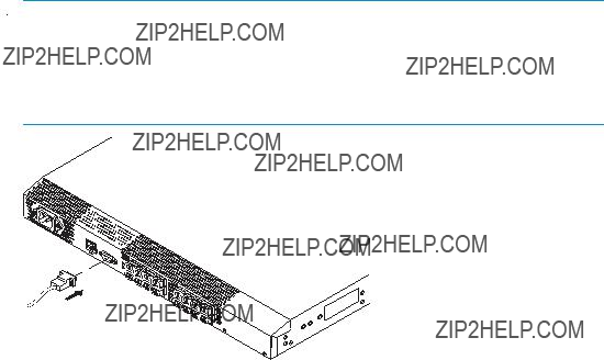
Make a serial connection
To make a serial connection through the SAN Switch serial port:
1.Insert the serial cable into the serial port on the switch.
2.Connect the serial cable to an
 NOTE:
NOTE:
If the serial port on the workstation uses an
0014b
Figure 20 Connecting the serial cable

 NOTE:
NOTE:
Figure 20 shows the 4/16 SAN Switch; however, this procedure is similar for all SAN Switches.
3.Close any serial communication programs running on the workstation.
4.Open a terminal emulator application (such as HyperTerminal on a PC or TERM in a UNIX environment) and configure the application as follows:
???In a Windows 95, 98, 2000, or NT environment:
???9600 bits per second
???8 data bits
???No parity
???1 stop bit
???No flow control
???In a UNIX environment, enter the following at the prompt: tip/dev/ttyb
Apply power to the switch and log in
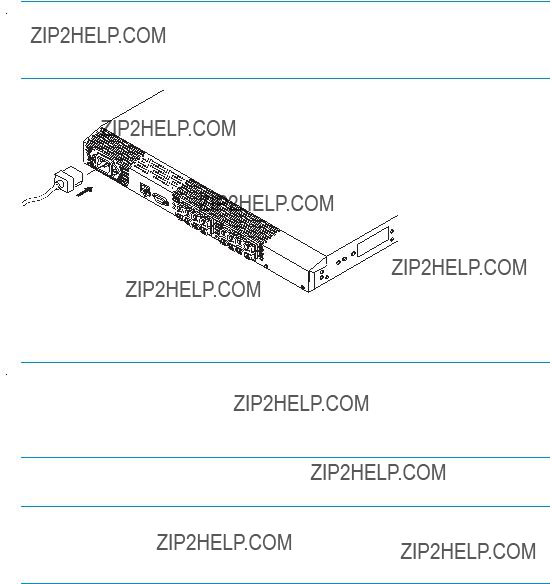
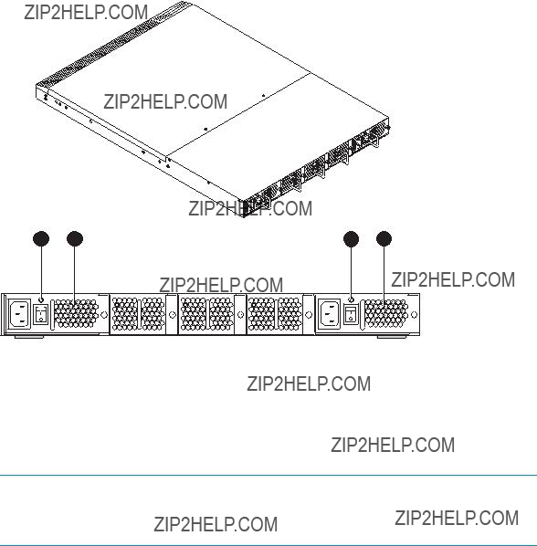
Once a serial connection is established, apply power to the switch:
1.Connect the power cord to a power inlet on the switch and a power source, as shown in Figure 21.
 NOTE:
NOTE:
The 4/32, 4/32B and 4/64 SAN Switch models use two power cords.
The 4/8 and 4/16 SAN Switches use one power cord.
0015b
Figure 21 Connecting the power cord
 NOTE:
NOTE:
To protect against AC failure on the 4/32, 4/32B and 4/64 SAN Switch models, connect each power cord to outlets on separate circuits. Verify that the cords have a minimum service loop of
2. To power on, set the two AC switches to the ON position (I).
 IMPORTANT:
The 4/8 and 4/16 SAN Switches utilize one power switch. The 4/32, 4/32B and 4/64 SAN Switches utilize two power switches.
The power supply LED lights green and the switch runs the
3. After POST and the boot process are completed, verify that the System Status and System Power LEDs light green.
4.When the terminal emulator application, which uses a serial connection, stops reporting information, press Enter to display the login prompt.
5.Log in using the administrative account; the logon is admin and the default password is password. Create up to two simultaneous admin sessions and four user sessions.
For more details, see the Fabric OS administrator???s guide and the Fabric OS command reference manual for the Fabric OS running on your switch.
Set the IP address
By default, the IP address is set to 10.77.77.77. To replace the default IP addressing information with the information provided by your network administrator:
1.Enter ipaddrset at the terminal emulator application prompt.
2.Enter the IP addressing information, as prompted.
3.Optional: Verify that the address is correct by issuing the ipaddrshow command at the prompt.
4.Record the IP address on the label located on the port side of the chassis.
For the 4/32, 4/32B and 4/64 SAN Switches, record the IP address on the
5.If the serial port is no longer required, log out of the serial console, remove the serial cable, and replace the safety plug in the serial port.
Create an Ethernet connection
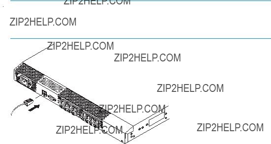
To create an Ethernet connection:
1.Connect an Ethernet cable to the Ethernet port and to the workstation, or to an Ethernet network containing the workstation, as shown in Figure 22 on page 58.
 NOTE:
NOTE:
Figure 22 shows the 4/16 SAN Switch; however, this procedure is similar for all SAN Switches.
0016b
Figure 22 Connecting the Ethernet cable
Once the Ethernet cable is connected, access the switch remotely via the CLI or the integrated Advanced Web Tools GUI software.
2. Log in to the switch via Telnet, using the admin account.
Modify the FC domain ID (optional)
You can modify the FC domain ID. The default FC domain ID is 1. If the switch is not powered on until after it is connected to the fabric, and the default FC domain ID is already in use, the domain ID for the new switch is automatically reset to a unique value. If the switch is connected to the fabric after it has been powered on, and the default domain ID is already in use, the fabric segments.
To determine the domain IDs that are currently in use, issue the fabricshow command. The number of domains is determined by your domain fabric licensing.
To modify the domain ID:
1.Issue the switchdisable command to disable the switch.
2.Issue the configure command. The prompts display sequentially: enter a new value or press Enter to accept each default value.
3.At the Fabric Parameters prompt, enter y and press Enter:
Fabric Parameters (yes, y, no, n): (no) y
4.Enter a unique domain ID, such as the domain ID used by the previous switch, if it is still available:
Domain: (1..239) [1] 3
5.Respond to the remaining prompts or press Ctrl+D to accept the default settings.
6.Issue the switchenable command to
7.Optional: Specify any custom status policies:
a.Issue the switchstatuspolicyset command. This command sets the policy parameters that determine the overall switch status.
b.Customize the status policies.
To deactivate the alarm for a particular policy, enter 0 at the prompt for that policy.
Install the SFP transceivers
The SAN Switch does not ship with SFPs. For a list of supported SFPs, see Table 2 on page 33.
The ports selected for use in trunking groups must meet specific requirements. For a list of these requirements, see the ISL Trunking chapter in the Fabric OS administrator???s guide.
To install the SFP transceivers:
1.Position the transceiver so that it is oriented correctly and insert it into a port until the latching mechanism clicks. The transceivers are keyed to ensure correct orientation. If the transceiver does not install easily, make sure it is oriented correctly.
For instructions specific to the transceiver you are using, see the transceiver manufacturer???s documentation.
2.Repeat step 1 for the remaining ports, as required.

Connect the cables
 CAUTION:
The minimum bend radius for a
To connect the cables to the SFP transceivers:
1.The cable connectors are keyed to ensure correct orientation. Orient a cable connector so that the key (the ridge on the side of the connector) aligns with the slot in the transceiver, and insert the cable into the transceiver until the latching mechanism clicks. If a cable does not install easily, make sure it is correctly oriented.
For detailed instructions on the cable type, see the cable manufacturer???s documentation.
2.Repeat Step 1 for the remaining transceivers, as required.
The cables used in trunking groups must meet specific requirements. For a list of these requirements, see the Fabric OS administrator???s guide.
Verify the configuration
To confirm that the switch is configured and ready for use:
1.Check the LEDs to verify that all components are functional. For information about LED patterns, see Interpreting LED activity on page 69.
2.Issue the switchshow command from the workstation. This command provides information about the switch and port status.
3.Issue the fabricshow command from the workstation. This command provides general information about the fabric.
Back up the configuration
HP recommends regular backups to ensure that a recent configuration is available. To back up the switch configuration to an FTP server:
1.Issue the configupload command.
2.Follow the prompts.
The command uploads the switch configuration to the server, making it available for downloading to a replacement switch, if necessary. For detailed instructions on backing up the configuration, see the Fabric OS administrator???s guide.
Set the switch date and time
The date and time switch settings are used for logging events. Switch operation does not depend on the date and time; a switch with an incorrect date and time value still functions properly.
You can synchronize the local time of the principal or primary Fabric Configuration Server (FCS) switch with that of an external Network Time Protocol (NTP) server.
To set the date and time for a switch (see Example 2 following the procedure):
1.Log in to the switch as admin.
2.Enter the date command at the CLI prompt, using the following syntax: date ???MMDDhhmm [CC]YY???
The values represent the following:
???MM is the month (01 ??? 12).
???DD is the date (01 ??? 31).
???hh is the hour (00 ??? 23).
???mm is minutes (00 ??? 59).
???CC is the century (19 ??? 20).
???YY is the year (00 ??? 99).
Year values greater than 69 are interpreted as
Example 2:
switch: admin> date
Fri May 5 21:50:00 UTC 1989 switch:admin>
switch:admin> date ???0624165203??? Tue Jun 24 16:52:30 UTC 2003 switch:admin>
Synchronize the local time with an external source
To synchronize the local time of the principal or primary FCS switch with that of an external NTP server:
1.Log in as admin.
2.Issue the tsclockserver [ipaddr] command.
The ipaddr variable represents the IP address of the NTP server that the switch can access. This argument is optional; by default, its value is LOCL (see Example 3).
Example 3:
switch:admin> tsclockserver
LOCL
switch:admin> tsclockserver 132.163.135.131 switch:admin>
Set the time zone
To set the time zone:
1.Log in as admin.
2.Issue the following tstimezone command: tstimezone[houroffset] [minuteoffset]
???For Pacific Standard Time, enter tstimezone
???For Mountain Standard Time, enter tstimezone
???For Central Standard Time, enter tstimezone
???For Eastern Standard Time, enter tstimezone
The default time zone for switches is Universal Time Conversion (UTC), which is eight hours ahead of Pacific Standard Time. The parameters listed do not apply if the time zone of the switches has already been changed from the default (eight hours ahead of PST).
See the tstimezone command in the Fabric OS command reference manual for more detailed information about the command parameters.
3.Repeat step 1 and step 2 on all switches for which the time zone needs to be set. The time zone is set only once; the value is stored in nonvolatile memory.
For U.S. time zones, Table 6 on page 63 provides the correct offset parameters for the tstimezone command.
Table 6 Time zone command values

3 Managing SAN Switches
This chapter describes the following topics:
???Powering on and off, page 66
???SAN Switch management features, page 67
???Managing SAN Switches from a single management station, page 67
???Interpreting LED activity, page 69
???4/8 and 4/16 SAN Switch LEDs, page 69
???4/8 and 4/16 SAN Switch LED patterns, page 70
???4/32 SAN Switch port side LEDs, page 74
???4/32 SAN Switch nonport side LEDs, page 78
???4/64 SAN Switch port side LEDs, page 79
???4/64 SAN Switch nonport side LEDs, page 82
???4/32B SAN Switch LEDs, page 85
???POST and boot specifications, page 88
???Interpreting POST results, page 89
???Diagnostic tests, page 89

Powering on and off
The following sections provide information on powering specific SAN Switch models on and off.
4/8 and 4/16 SAN Switch models
To power on:
1.Connect one end of the power cord to the AC inlet on the switch; connect the other end to a power source.
2.Set the AC power switch to I.
The switch runs POST each time it is powered on, reset, or rebooted. POST requires approximately three minutes.
To power off:
1.Set the AC power switch to O.
2.Remove the power cords from the power sources.
 NOTE:
NOTE:
Removing all power from the switch triggers a system reset. All devices are returned to their initial state the next time the switch is powered on.
4/32, 4/32B and 4/64 SAN Switch models
Connect one or both power cords to the AC power inlets on the switch; connect the other end to a power source.
To power on, set both AC power switches to I. Power is supplied to the switch as soon as the first power supply is connected and powered on.
To power off, set both AC power switches to O and remove the AC power cord from the power source.
 NOTE:
NOTE:
Removing all power from the switch triggers a system reset. All devices are returned to their initial states the next time the switch is powered on.

SAN Switch management features
SAN Switches use
When running IP over FC, these management tools must be supported by both HBA and HBA drivers. For a list of supported HBAs, see the HP StorageWorks SAN design guide: http://www.hp.com/go/sandesignguide.
Table 7 Management tools
Managing SAN Switches from a single management station
A management station connected to one switch via Ethernet can also be used to manage other switches connected to the first switch via FC. To do so, set the gateway address of the first switch to the gateway address of the subnet that the first switch resides on. Then, set the FC gateway address of each of the other switches to the FCIP address of the first switch. (See Table 8 for an example of address sets for a management station with three switches).
 NOTE:
NOTE:
The disadvantage of this method is that the management station can only communicate with the switches.
Table 8 Example of a set of gateway addresses
Interpreting LED activity
System activity and status can be determined through the LEDs on the switch. There are three possible LED states that display either green or amber:
???A steady light
???A flashing light
???No light
LEDs display either green or amber colors. A steady green light indicates a healthy state. Sometimes, the LEDs flash any of the colors during boot, POST, or other diagnostic tests. This is normal; it does not indicate a problem unless the LEDs do not indicate a healthy state after all boot processes and diagnostic tests are complete.
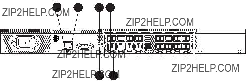
4/8 and 4/16 SAN Switch LEDs
The LEDs are shown in Figure 23.
Figure 23 shows the LEDs on the port side of the 4/16 SAN Switch.
scale: 5/16" = 1"
Figure 23 4/8 and 4/16 SAN Switch LED locations
4/8 and 4/16 SAN Switch LED patterns
Table 9 and Table 10 on page 71 summarize LED locations, colors, and recommended actions.
Power Status LED patterns
The system and power LED patterns are described in Table 9.
Table 9 4/8 and 4/16 SAN Switch LED patterns
4/8 and 4/16 SAN Switch system Status LED patterns
The system status LED patterns are described in Table 10.
Table 10 System status LED patterns during normal operation
4/8 and 4/16 SAN Switch port LED patterns
Each port includes two LEDs: a Port Speed indicator and a Port Status indicator. Table 11 describes the LED locations, colors, and recommended actions.
Table 11 Port LED patterns during normal operation
4/8 and 4/16 SAN Switch Ethernet LED patterns
Each Ethernet port has two LEDs described in Table 12.
Table 12 Ethernet LED patterns
4/32 SAN Switch port side LEDs
The 4/32 SAN Switch has the following port side LEDs:
???System Status
???Power Status
???Port Status
???Port Speed
Figure 24 describe the locations of the port side LEDs.
scale: 5/16" = 1"
Figure 24 4/32 SAN Switch port side LEDs
Table 13 describes the 4/32 SAN Switch port side LEDs.
Table 13 4/32 SAN Switch port side LED patterns
4/32 SAN Switch nonport side LEDs
The 4/32 SAN Switch has the following nonport side LEDs:
???Two Power Supply LEDs
???Three Fan Status LEDs
Figure 25 shows the locations of the nonport side LEDs.
MRO25013a
Figure 25 4/32 SAN Switch nonport side LEDs
Table 14 describes the 4/32 SAN Switch nonport side LEDs.
Table 14 4/32 SAN Switch nonport side LED patterns
4/64 SAN Switch port side LEDs
The 4/64 SAN Switch integrates the following port side LEDs:
???System Status LED
???Power Status LED
???Two Ethernet Port LEDs
???One Port Status LED
???Port Speed LED for each port on the switch. These LEDs are displayed below each pair of Fibre Channel ports. The LEDs are located in the array in the same relative positions as the ports.
Figure 26 on page 80 identifies the LEDs on the port side of the switch. Table 15 on page 81 describes the port side LED patterns.
9
IOIOI
!
Figure 26 4/64 SAN Switch port side LEDs
Table 15 4/64 SAN Switch port side LED patterns
4/64 SAN Switch nonport side LEDs
The 4/64 SAN Switch has the following nonport side LEDs:
???One power supply LED above the AC power switch on each power supply
???One fan status LED at the bottom of each fan assembly
Figure 27 on page 83 identifies the nonport side LEDs of the switch. Table 16 on page 84 describes the nonport side LED patterns.
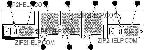
Figure 27 4/64 SAN Switch nonport side LEDs
Table 16 4/64 SAN Switch nonport side LED patterns during normal operation
4/32B SAN Switch LEDs
The 4/32B SAN Switch model integrates the following LEDs:
???System Status LED
???Power Status LED
???Port Status LEDs (32), one for each FC port, located directly above the ports
???Power Supply status LED on each power supply FRU, in the upper right corner
Figure 28 and Table 17 identify the port side LEDs.
1 2
Figure 28 4/32B SAN Switch port side LEDs
Table 17 4/32B SAN Switch LED patterns during normal operation
POST and boot specifications
When the switch is powered on or rebooted, the switch performs POST. Total boot time with POST is at least three minutes.
Use fastboot to bypass POST after subsequent reboots. For more information about the fastboot command, refer to the Fabric OS command reference manual for the Fabric OS version running on your switch.
POST
POST is a system check that is performed each time the switch is powered on, rebooted, or reset. During POST, the LEDs flash different colors. Any errors that occur during POST appear in the error log.
Monitor POST diagnostic tests via the error log or the CLI. The POST process consists of:
???Displaying preliminary POST diagnostics
???Initializing the operating system
???Initializing the hardware
???Performing diagnostic tests that check several functions, including circuitry, port functionality, memory, statistics counters, and serialization
Boot
Boot completes in approximately three minutes during POST. The boot process consists of:
???Defining the universal port configuration set
???Initializing the links
???Analyzing the fabric
If any ports are connected to other switches, the switch participates in a fabric configuration.
???Assigning domain IDs and port addresses
???Constructing the unicast routing tables
???Enabling normal port operation

Interpreting POST results
To determine whether POST completed successfully and whether any errors were detected:
1.Verify that the switch LEDs indicate that all components are healthy. See:
???4/8 and 4/16 SAN Switch LED patterns on page 70
???4/32 SAN Switch port side LEDs on page 74
???4/32 SAN Switch nonport side LEDs on page 78
???4/64 SAN Switch port side LEDs, page 79
???4/32B SAN Switch LEDs, page 85
If one or more LEDs do not display a healthy state, verify that the LEDs are not set to beacon by issuing the switchshow command.
2.Verify that the switch prompt appears on a workstation monitor connected to the switch. If there is no switch prompt when POST completes, press Enter. If the switch prompt still does not appear, try opening another Telnet session or accessing the results using another management tool. If this does not work, the switch did not successfully complete POST. Contact HP Technical Support.
3.Review the system log for errors. Any errors detected during POST are written to the system log, accessible through the errshow command. For information about this command, refer to the Fabric OS Command Reference. For information about error messages, refer to the System Message Reference.
Diagnostic tests
In addition to POST, Fabric OS includes diagnostic tests to help troubleshoot the hardware and firmware. This includes tests of internal connections and circuitry, fixed media, and transceivers and cables.
The tests are implemented by command, either through a Telnet session or through a terminal set up for a serial connection to the switch. Some tests require the ports to be connected by external cables to allow diagnostics to verify the serializer/deserializer interface, transceiver, and cable.
Diagnostic tests are run at link speeds of 1 Gb/s, 2 Gb/s, and 4 Gb/s.
 CAUTION:
Diagnostic tests might temporarily lock the transmit and receive speed of the links during diagnostic testing.
4 Installing
The 4/8 and 4/16 SAN Switches do not require regular maintenance and do not contain any FRUs; these switches are themselves FRUs. The 4/32 SAN Switch and 4/64 SAN Switches contain two FRUs: the power supply and the fan assembly.
This chapter provides the following information:
???Replacing the SAN Switch 4/32 power supply, page 91
???Replacing the 4/32 SAN Switch fan assembly, page 96
???Replacing the SAN Switch 4/64 power supply, page 99
???Replacing the 4/64 SAN Switch fan assembly, page 103
???Replacing the 4/32B SAN Switch Power Supply/Fan Assembly Unit, page 106
???Replacing an SFP, page 110
Replacing the 4/32 SAN Switch power supply
The 4/32 SAN Switch uses two power supplies, as shown in Figure 29. The Fabric OS identifies the power supplies from left to right on the nonport side as PS2 (on the left) and PS1 (on the right).
Scale: 1/8" = 1"
MRO25014a
Figure 29 4/32 SAN Switch power supplies on the nonport side
 CAUTION:
Disassembling any part of the power supply voids the part warranty and regulatory certifications. There are no
Table 18 describes the Power Supply Status LEDs and corrective actions.
Table 18 4/32 SAN Switch Power Supply Status LEDs
Items required
Replacing a 4/32 SAN Switch power supply should take less than two minutes and requires the following items:
???New power supply
???Phillips #1 screwdriver
Procedure
To replace a power supply in the 4/32 SAN Switch, see Figure 30 on page 94:
1.If the switch will remain powered on, verify that the functioning power supply (the one not being replaced) has been powered on for at least four seconds and displays a green LED.
2.If the power supply you are replacing is not already powered off, press the AC power switch to power it off.
3.Unplug the power cord from the power supply you are replacing.
4.Using a Phillips screwdriver, unscrew the captive screw on the power supply you are replacing.
5.Remove the power supply from the chassis by pulling its handle out and away from the chassis.
6.Orient the new power supply as shown in Figure 30 on page 94, with the AC power receptacle on the left.
7.Gently push the power supply into the chassis until it is firmly seated.
Scale: 1/4" = 1"
1
2
Figure 30 Installing the power supply in a 4/32 SAN Switch

 CAUTION:
Do not force the installation. If the power supply does not slide in easily, make sure that it is oriented correctly before continuing.
8.Secure the power supply to the chassis by tightening the captive screw.
9.Plug the power cord into the power supply and then press the AC power switch to turn it on.
10.Verify that the LED on the new power supply displays a steady green light while the switch is operating (see Table 18 on page 93). If the LED is not green, make sure that the power supply is firmly seated.
Replacing the 4/32 SAN Switch fan assembly
The 4/32 SAN Switch contains three fan assemblies, as shown in Figure 31. Fabric OS identifies the fans from left to right as Fan 3, Fan 2, and Fan 1.
Scale: 1/8" = 1"
MRO25016a
Figure 31 4/32 SAN Switch fan assemblies on the nonport side
Table 19 describes the Fan Status LEDs and provides corrective actions.
Table 19 4/32 SAN Switch Fan Status LED behavior
Items required
Replacing a 4/32 SAN Switch fan assembly takes approximately two minutes and requires the following items:
???New fan assembly
???Phillips #1 screwdriver
Procedure
To replace a fan assembly in a 4/32 SAN Switch:
1.Unscrew the captive screw on the fan assembly using a Phillips screwdriver.
2.Remove the fan assembly from the chassis by pulling its handle out and away from the chassis.
3.Orient the new fan assembly as shown in Figure 32, with the captive screw on the right.
4.Gently push the new fan assembly into the chassis until it is firmly seated.
5.Secure the fan assembly to the chassis by tightening the captive screw.
Scale: 1/4" = 1"
2
1
Figure 32 Installing the fan assembly in a 4/32 SAN Switch
 CAUTION:
Do not force the installation. If the fan assembly does not slide in easily, make sure that it is oriented correctly before continuing.
6.Verify that the Fan Status LED does not display a steady amber light for more than five seconds, which indicates a fault (see Table 19 on page 97).
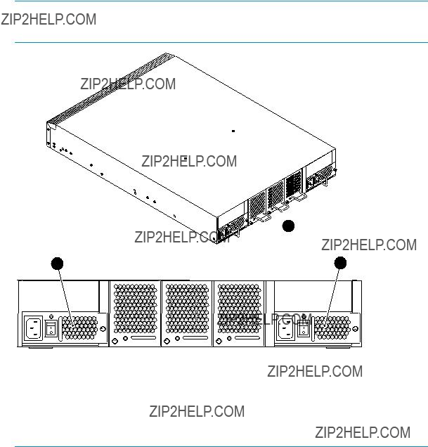
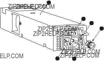
Replacing the 4/64 SAN Switch power supply
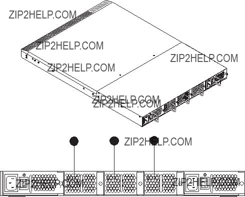
The 4/64 SAN Switch uses two power supplies, as shown in Figure 33. The Fabric OS identifies the power supplies from right to left on the nonport side as Power Supply #1 (on the right) and Power Supply #2 (on the left).
 IMPORTANT:
Operate the switch with both power supplies to maintain redundancy.
25187a
3. Power supply 1
Figure 33 4/64 SAN Switch power supplies on the nonport side
 CAUTION:
Disassembling any part of the power supply voids the part warranty and regulatory certifications. There are no
Items required
Replacing a 4/64 SAN Switch power supply should take less than two minutes and requires the following items:
???New power supply
???Phillips #1 screwdriver
Procedure
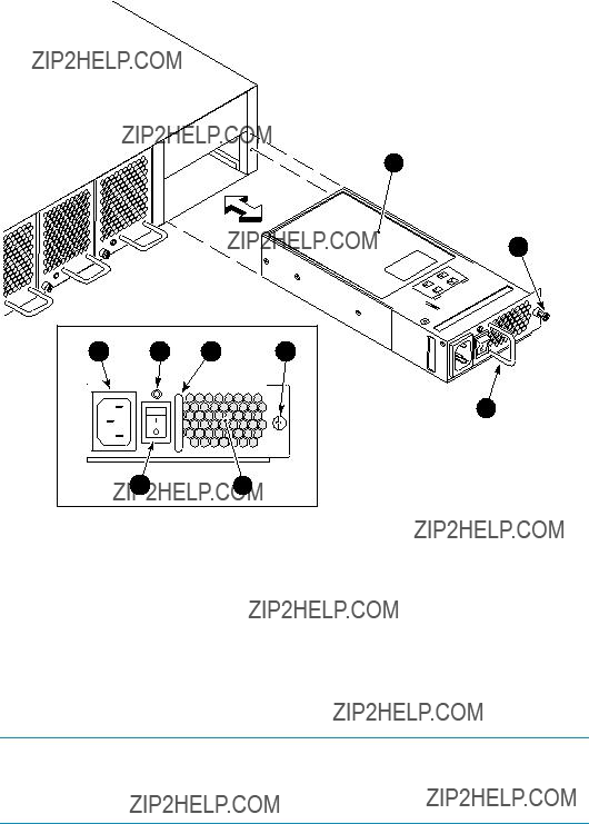
To replace a power supply in the 4/64 SAN Switch:
1.If the switch will remain powered on, verify that the functioning power supply (the one not being replaced) has been powered on for at least four seconds and displays a green LED.
2.If the power supply you are replacing is not already powered off, press the AC power switch to power it off. See Figure 34 for the location of the AC power switch and a list of power supply components.
3.Unplug the power cord from the power supply you are replacing.
4.Using a Phillips screwdriver, unscrew the captive screw on the power supply you are replacing.
5.Remove the power supply from the chassis by pulling its handle out and away from the chassis.
6.Orient the new power supply as shown in Figure 34, with the AC power receptacle on the left.
7.Gently push the power supply into the chassis until it is firmly seated.
7
8
9
25188a
Figure 34 Installing the power supply in the 4/64 SAN Switch
 CAUTION:
Do not force the installation. If the power supply does not slide in easily, make sure that it is correctly oriented before continuing.
8.Secure the power supply to the chassis by tightening the captive screw.
9.Plug the power cord into the power supply and then press the AC power switch to turn it on.
10.Verify that the LED on the new power supply displays a steady green light while the switch is operating (see Table 18 on page 93). If the LED is not green, make sure that the power supply is firmly seated.
Fabric OS identifies the power supplies in a 4/64 SAN Switch from left to right as PS2 and PS1, as shown in Figure 34 on page 102.
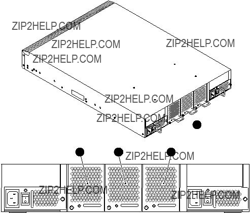
Replacing the 4/64 SAN Switch fan assembly
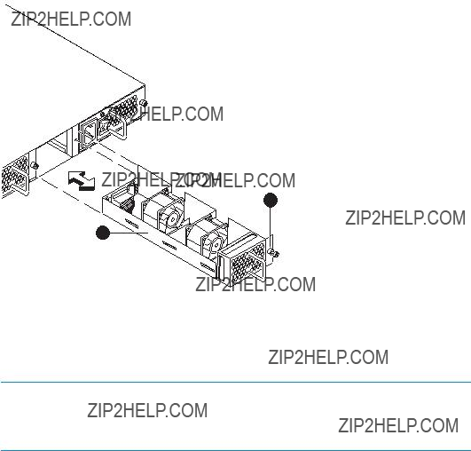
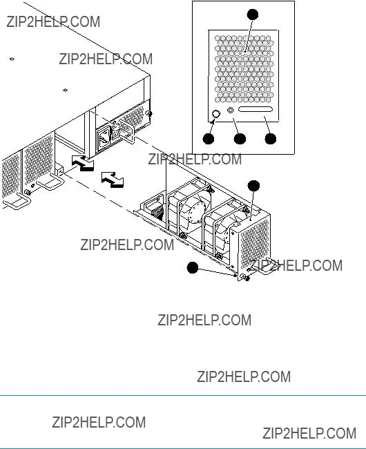
The 4/64 SAN Switch contains three fan assemblies, as shown in Figure 35. Fabric OS identifies the fans from left to right as Fan 3, Fan 2, and Fan 1.
1
25185a
Figure 35 4/64 SAN Switch fan assemblies on the nonport side
Table 20 describes the Fan Status LEDs and provides corrective actions.
Table 20 Fan Status LEDs
Items required
Replacing a 4/64 SAN Switch fan assembly takes approximately two minutes and requires the following items:
???New fan assembly
???Phillips #1 screwdriver
Procedure
To replace a fan assembly in a 4/64 SAN Switch:
1.Unscrew the captive screw on the fan assembly using a Phillips screwdriver.
2.Remove the fan assembly from the chassis by pulling the handle out away from the chassis.
3.Orient the new fan assembly as shown in Figure 36 on page 105, with the captive screw on the left.
4.Gently push the new fan assembly into the chassis until it is firmly seated.
5.Secure the fan assembly to the chassis by tightening the captive screw.
1
Scale:
 3/8" = 1"
2 3 4
5
Figure 36 Inserting the fan assembly in a 4/64 SAN Switch
 CAUTION:
Do not force the installation. If the fan assembly does not slide in easily, make sure that it is oriented correctly before continuing.
6.Verify that the Fan Status LED does not display a steady amber color for more than five seconds, which indicates a fault (see Table 19 on page 97).
Figure 36 identifies the fan assembly components.
Replacing the 4/32B SAN Switch Power Supply/Fan
Assembly Unit
Read this section for Power Supply/Fan Assembly Unit replacement procedures.
Power Supply/Fan Assembly overview
The 4/32B SAN Switch fans are fixed inside the integrated power supply/fan FRU to provide necessary airflow to cool the whole system. There is one fan located in the rear section of each FRU. The system software sets fan speed and measures their speeds through the tachometer interface.
The two power supply/fan assembly FRU units are
The Fabric OS identifies the Power Supplies as follows (viewing the switch from the port side):
???PS1 on the left
???PS2 on the right
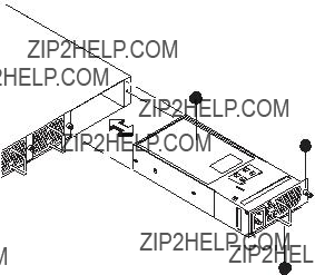
Figure 37 identifies Power Supply/Fan Assembly Unit components.
1
2
3
4
Figure 37 4/32B SAN Switch Power Supply/Fan Assembly Unit

 CAUTION:
Disassembling any part of the fan assembly voids the part warranty and regulatory certifications. There are no
Because the cooling system relies on pressurized air, do not leave any of the fan assembly slots empty longer than two minutes while the switch is operating. If a fan assembly fails, leave it installed in the switch until it can be replaced.
Maintain the two Power Supply/Fan assemblies in operating condition to provide redundancy.
Table 21 lists power supply/fan assembly unit status LED descriptions, and required actions.
Table 21 4/32B SAN Switch power supply/fan assembly unit status LED
How to determine to replace the Power Supply/Fan Assembly Unit
Verifying if the Power Supply requires replacing:
???Check the Power Supply status LED next to the I/O switch. If the Power Supply status LED is not on, verify that the Power Supply is on and seated and the power cord is connected to a functioning power source. If the light does not turn green, the Power Supply needs to be replaced.
???In Advanced Web Tools, click the Power Status icon.
???Type psShow at the command prompt to display Power Supply status as follows: switch:admin> psshow
Power Supply #1 is OK Power Supply #2 is OK
Verifying if the Fan Assembly requires replacing:
???Check the System Status LED. If the System Status LED is flashing amber and green, it could mean the fan has failed. Check the management interface and the error log for details on the cause of status.
???In Advanced Web Tools, check the Fan Status icon background color. It will be either yellow or red if the fan has failed. When the fan is functioning correctly, the background color is green.
???Type fanShow at the command prompt to display fan status as follows: switch:admin> fanshow
Fan 1 is OK, speed is 7105 RPM Fan 2 is OK, speed is 7258 RPM

Items required
Replacing a 4/32B SAN Switch Power Supply/Fan Assembly Unit takes approximately two minutes, and requires the following items:
???4/32B SAN Switch
???New Power Supply/Fan Assembly Unit
???Phillips #1 screwdriver
Procedure
To replace an existing Power Supply/Fan Assembly Unit:
 WARNING!
The 4/32B SAN Switch utilizes two power cords. Be aware that with the removal of a single power cord and power supply/fan assembly unit, power is still present in the switch.
1.If the switch is to continue operating during the replacement, verify that the other Power Supply/Fan Assembly Unit (the one not being replaced) has been powered on for at least four seconds and has a green LED.
2.If the Power Supply/Fan Assembly Unit you are replacing is not already off, press the AC power switch to ???O??? to power it off. See Figure 38 for locating the power switch.
3.Lift the power cord retainer up to free the power cord for removal.
4.Unplug the power cord from the Power Supply/Fan Assembly Unit that you are replacing.
5.Unscrew the captive screw on the Power Supply/Fan Assembly Unit that you are replacing.
6.Remove the Power Supply/Fan Assembly Unit from the chassis by pulling the power cord retainer on the power supply/ fan assembly unit out, away from the chassis.
7.Install the new Power Supply/Fan Assembly Unit in the chassis:
a.Orient the Power Supply/Fan Assembly Unit as shown in Figure 38, with the captive screw on the right.
25276a
Figure 38 Inserting the Power Supply/Fan Assembly Unit in the 4/32B SAN Switch
b. Gently push the power supply into the chassis until it is seated.
 CAUTION:
Do not force the installation. Verify that the unit is oriented correctly before continuing.
c.Secure the Power Supply/Fan Assembly Unit to the chassis by screwing in the captive screw.
8.Plug the power cord in to the Power Supply/Fan Assembly Unit and press the AC power switch to ???I??? to turn it on.
9.Fasten the power cord in place by pulling the power cord retainer down over the power cord plug.
10.Verify that the LED on the new Power Supply/Fan Assembly Unit displays a steady green light while the switch is operating. If the LED is not green, ensure that the Power Supply/Fan Assembly Unit is firmly seated.
11.Optionally, type psShow at the command line prompt to display Power Supply/Fan Assembly Unit status. Fabric OS identifies the Power Supply/Fan Assembly Unit in the 4/32B SAN Switch from left to right as PS1 and PS2 respectively. See Figure 38.
Replacing an SFP
To remove a faulty SFP transceiver:
1.Press and hold the cable release.
2.Remove the cable from the transceiver.
3.Pull the bale (wire handle) to release the transceiver.
4.Grasp the transceiver by the bale and gently, but firmly, pull it out of the port.
 CAUTION:
If the SFP you does not have a bale, use a small implement, such as a screwdriver, to press and release the trigger beneath the port.
5. Repeat this procedure for the remaining ports, as required. To install a replacement SFP:
1.Make sure that the bale is in the unlocked position, and then place the SFP in the correctly oriented position on the port. See Figure 39.
 NOTE:
NOTE:
Each SFP includes a
2. Slide the SFP into the port until you feel it click into place, and then close the bale.
Figure 39 Installing the SFP

A Regulatory compliance and safety
Regulatory compliance
Federal Communications Commission notice for Class A equipment
This equipment has been tested and found to comply with the limits for a Class A digital device, pursuant to Part 15 of the FCC Rules. These limits are designed to provide reasonable protection against harmful interference when the equipment is operated
in a commercial environment. This equipment generates, uses and can radiate radio frequency energy and, if not installed and used in accordance with the instruction manual, may cause harmful interference to radio communications. Operation of this equipment in a residential area is likely to cause harmful interference, in which case the user will be required to correct the interference at his own expense. The end user of this product should be aware that any changes or modifications made to this equipment without the approval of
Declaration of conformity for products marked with the FCC logo, United States only
This device complies with Part 15 of the FCC Rules. Operation is subject to the following two conditions: (1) this device may not cause harmful interference, and (2) this device must accept any interference received, including interference that may cause undesired operation.
For questions regarding your product, visit http://www.hp.com.
For questions regarding this FCC declaration, contact us by mail or telephone:
???
P.O. Box 692000, Mailstop 510101 Houston, TX
???
To identify this product, refer to the part, Regulatory Model Number, or product number found on the product.

Modifications
The FCC requires the user to be notified that any changes or modifications made to this device that are not expressly approved by
Cables
Connections to this device must be made with shielded cables with metallic RFI/EMI connector hoods in order to maintain compliance with FCC Rules and Regulations.
Regulatory compliance identification numbers
For the purpose of regulatory compliance certifications and identification, your product has been assigned a unique Regulatory Model Number. The RMN can be found on the product nameplate label, along with all required approval markings and information.
When requesting compliance information for this product, always refer to this RMN. The Regulatory Model Number should not be confused with the marketing name or model number of the product.
The Regulatory Model Number for the 4/8 and 4/16 SAN Switches is
The Regulatory Model Number for the 4/32B SAN Switch is
Laser device
All HP systems equipped with a laser device comply with safety standards, including International Electrotechnical Commission (IEC) 825. With specific regard to the laser, the equipment complies with laser product performance standards set by government agencies as a Class 1 laser product. The product does not emit hazardous light.
Laser safety warning
 WARNING!
To reduce the risk of exposure to hazardous radiation:
???Do not try to open the laser device enclosure. There are no
???Do not operate controls, make adjustments, or perform procedures to the laser device other than those specified herein.
???Allow only HP authorized service technicians to repair the laser device.

Certification and classification information
This product contains a laser internal to the fiber optic (FO) transceiver for connection to the Fibre Channel communications port.
In the USA, the FO transceiver is certified as a Class 1 laser product conforming to the requirements contained in the Department of Health and Human Services (DHHS) regulation 21 CFR, Subchapter J. A label on the plastic FO transceiver housing indicates the certification.
Outside the USA, the FO transceiver is certified as a Class 1 laser product conforming to the requirements contained in IEC
Laser product label
The optional label in Figure 40 or equivalent may be located on the surface of the HP supplied laser device.
Figure 40 Class 1 laser product label
This optional label indicates that the product is classified as a CLASS 1 LASER PRODUCT. This label may appear on the laser device installed in your product.
International notices and statements
Canadian notice (avis Canadien)
Class A equipment
This Class A Digital apparatus meets all requirements of the Canadian
Cet appareil num??rique de la classe A respecte toutes les exigences du R??glement sur le mat??riel brouilleur du Canada.

European Union notice
Products bearing the CE Marking comply with both the EMC Directive (89/336/EEC) and the Low Voltage Directive (73/23/EEC) issued by the Commission of the European Community and if this product has telecommunication functionality, the R&TTE Directive (1995/5/EC).
Compliance with these directives implies conformity to the following European Norms (the equivalent international standards and regulations are in parentheses):
???EN55022 (CISPR 22) ??? Electromagnetic Interference
???EN55024
???
???
???EN60950 (IEC60950) ??? Product Safety
???Also approved under UL 60950/CSA C22.2 No.
BSMI notice

Japanese notice
Korean notices
Safety
Battery replacement notice
Your switch is equipped with a lithium manganese dioxide, a vanadium pentoxide, or an alkaline internal battery or battery pack. There is a danger of explosion and risk of personal injury if the battery is incorrectly replaced or mistreated. Replacement is to be done by an HP authorized service provider using the HP spare part designated for this product. For more information about battery replacement or proper disposal, contact an HP authorized service provider.
 WARNING!
Your switch contains an internal lithium manganese dioxide, a vanadium pentoxide, or an alkaline battery pack. There is risk of fire and burns if the battery pack is not properly handled. To reduce the risk of personal injury:
???Do not attempt to recharge the battery.
???Do not expose to temperatures higher than 60 ??C.
???Do not disassemble, crush, puncture, short external contacts, or dispose of in fire or water.
???Replace only with the HP spare part designated for this product.
Batteries, battery packs, and accumulators should not be disposed of together with the general household waste. To forward them to recycling or proper disposal, please use the public collection system or return them to HP, an authorized HP Partner, or their agents.
For more information about battery replacement or proper disposal, contact an HP authorized reseller or service provider.
Taiwan battery recycling notice
The Taiwan EPA requires dry battery manufacturing or importing firms in accordance with Article 15 of the Waste Disposal Act to indicate the recovery marks on the batteries used in sales, givaway, or promotion. Contact a qualified Taiwanese recycler for proper battery disposal.
Power cords
The power cord set must meet the requirements for use in the country where the product was purchased. If the product is to be used in another country, purchase a power cord that is approved for use in that country.
The power cord must be rated for the product and for the voltage and current marked on the product electrical ratings label. The voltage and current rating of the cord should be greater than the voltage and current rating marked on the product. In addition, the diameter of the wire must be a minimum of 1.00 mm2 or 18 AWG, and the length of the cord must be between 1.8 m, (6 ft) and 3.6 m (12 ft). If you have questions about the type of power cord to use, contact an HP authorized service provider.
 NOTE:
NOTE:
Route power cords so that they will not be walked on and cannot be pinched by items placed upon or against them. Pay particular attention to the plug, electrical outlet, and the point where the cords exit from the product.
Japanese power cord statement

Waste Electrical and Electronic Equipment directive
English notice
Disposal of waste equipment by users in private households in the European Union
This symbol on the product or on its packaging indicates that this product must not be disposed of with your other household waste. Instead, it is your responsibility to dispose of your waste equipment by handing it over to a designated collection point for recycling of waste electrical and electronic equipment. The separate collection and recycling of your waste equipment at the time of disposal will help to conserve natural resources and ensure that it is recycled in a manner that protects human health and the environment. For more information about where you can drop off your waste equipment for recycling, please contact your local city office, your household waste disposal service, or the shop where you purchased the product.
Dutch notice
Verwijdering van afgedankte apparatuur door
Dit symbool op het product of de verpakking geeft aan dat dit product niet mag worden gedeponeerd bij het normale huishoudelijke afval. U bent zelf verantwoordelijk voor het inleveren van uw afgedankte apparatuur bij een inzamelingspunt voor
het recyclen van oude elektrische en elektronische apparatuur. Door uw oude apparatuur apart aan te bieden en te recyclen, kunnen natuurlijke bronnen worden behouden en kan het materiaal worden hergebruikt op een manier waarmee de volksgezondheid en het milieu worden beschermd. Neem contact op met uw gemeente, het afvalinzamelingsbedrijf of de winkel waar u het product hebt gekocht voor meer informatie over inzamelingspunten waar u oude apparatuur kunt aanbieden voor recycling.
Czechoslovakian notice
Likvidace za?? ??zen?? soukrom??mi dom??c??mi u??ivateli v Evropsk?? unii
Tento symbol na produktu nebo balen?? ozna?? uje v??robek, kter?? nesm?? b??t vyhozen spolu s ostatn??m dom??c??m odpadem. Povinnost?? u??ivatele je p?? edat takto ozna?? en?? odpad na p?? edem ur?? en?? sb??rn?? m??sto pro recyklaci elektrick??ch a elektronick??ch
za?? ??zen??. Okam??it?? t?? ??d??n?? a recyklace odpadu pom????e uchovat p?? ??rodn?? prost?? ed?? a zajist?? takov?? zp??sob recyklace, kter?? ochr??n?? zdrav?? a ??ivotn?? prost?? ed?? ?? lov??ka. Dal???? informace o mo??nostech odevzd??n?? odpadu k recyklaci z??sk??te na p?? ??slu??n??m obecn??m nebo m??stsk??m ???? ad??, od firmy zab??vaj??c?? se sb??rem a svozem odpadu nebo v obchod??, kde jste produkt zakoupili.
Estonian notice
Seadmete j????tmete k??rvaldamine eramajapidamistes Euroopa Liidus
See tootel v??i selle pakendil olev s??mbol n??itab, et k??nealust toodet ei tohi koos teiste majapidamisj????tmetega k??rvaldada. Teie kohus on oma seadmete j????tmed k??rvaldada, viies need elektri- ja elektroonikaseadmete j????tmete ringlussev??tmiseks selleks etten??htud kogumispunkti. Seadmete j????tmete eraldi kogumine ja ringlussev??tmine k??rvaldamise ajal aitab kaitsta loodusvarasid ning tagada, et ringlussev??tmine toimub viisil, mis kaitseb inimeste tervist ning keskkonda. Lisateabe saamiseks selle kohta, kuhu oma seadmete j????tmed ringlussev??tmiseks viia, v??tke palun ??hendust oma kohaliku linnakantselei, majapidamisj????tmete k??rvaldamise teenistuse v??i kauplusega, kust Te toote ostsite.

Finnish notice
Laitteiden h??vitt??minen kotitalouksissa Euroopan unionin alueella
Jos tuotteessa tai sen pakkauksessa on t??m?? merkki, tuotetta ei saa h??vitt???? kotitalousj??tteiden mukana. T??ll??in h??vitett??v?? laite on toimitettava s??hk??laitteiden ja elektronisten laitteiden kierr??tyspisteeseen. H??vitett??vien laitteiden erillinen k??sittely ja kierr??tys auttavat s????st??m????n luonnonvaroja ja varmistamaan, ett?? laite kierr??tet????n tavalla, joka est???? terveyshaitat ja suojelee luontoa. Lis??tietoja paikoista, joihin h??vitett??v??t laitteet voi toimittaa kierr??tett??v??ksi, saa ottamalla yhteytt?? j??tehuoltoon tai liikkeeseen, josta tuote on ostettu.
French notice
??limination des appareils mis au rebut par les m??nages dans l???Union europ??enne
Le symbole appos?? sur ce produit ou sur son emballage indique que ce produit ne doit pas ??tre jet?? avec les d??chets m??nagers ordinaires. Il est de votre responsabilit?? de mettre au rebut vos appareils en les d??posant dans les centres de collecte publique d??sign??s pour le recyclage des ??quipements ??lectriques et ??lectroniques. La collecte
et le recyclage de vos appareils mis au rebut ind??pendamment du reste des d??chets contribue ?? la pr??servation des ressources naturelles et garantit que ces appareils seront recycl??s dans le respect de la sant?? humaine et de l???environnement. Pour obtenir plus d???informations sur les centres de collecte et de recyclage des appareils mis au rebut, veuillez contacter les autorit??s locales de votre r??gion, les services de collecte des ordures m??nag??res ou le magasin dans lequel vous avez achet?? ce produit.

German notice
Entsorgung von Altger??ten aus privaten Haushalten in der EU
Das Symbol auf dem Produkt oder seiner Verpackung weist darauf hin, dass das Produkt nicht ??ber den normalen Hausm??ll entsorgt werden darf. Benutzer sind verpflichtet, die Altger??te an einer R??cknahmestelle f??r Elektro- und
Greek notice


 .
. 


 ,
, 


 .
.


 .
. 


 ,
, 


 ,
, 


 .
.

Hungarian notice
K??sz??l??kek mag??nh??ztart??sban t??rt??n?? selejtez??se az Eur??pai Uni?? ter??let??n
A k??sz??l??ken, illetve a k??sz??l??k csomagol??s??n l??that?? azonos szimb??lum annak jelz??s??re szolg??l, hogy a k??sz??l??k a selejtez??s sor??n az egy??b h??ztart??si hullad??kt??l elt??r?? m??don kezelend??. A v??s??rl?? a hullad??kk?? v??lt k??sz??l??ket k??teles a kijel??lt
gy??jt??helyre sz??ll??tani az elektromos ??s elektronikai k??sz??l??kek ??jrahasznos??t??sa c??lj??b??l. A hullad??kk?? v??lt k??sz??l??kek selejtez??skori begy??jt??se ??s ??jrahasznos??t??sa hozz??j??rul a term??szeti er??forr??sok meg??rz??s??hez, valamint biztos??tja a selejtezett term??kek k??rnyezetre ??s emberi eg??szs??gre n??zve biztons??gos feldolgoz??s??t. A begy??jt??s pontos hely??r??l b??vebb t??j??koztat??st a lakhelye szerint illet??kes ??nkorm??nyzatt??l, az illet??kes szem??teltakar??t?? v??llalatt??l, illetve a term??ket el??rus??t?? helyen kaphat.
Italian notice
Smaltimento delle apparecchiature da parte di privati nel territorio dell???Unione Europea
Questo simbolo presente sul prodotto o sulla sua confezione indica che il prodotto
non pu?? essere smaltito insieme ai rifiuti domestici. ?? responsabilit?? dell???utente smaltire le apparecchiature consegnandole presso un punto di raccolta designato al riciclo e allo smaltimento di apparecchiature elettriche ed elettroniche. La raccolta differenziata e il corretto riciclo delle apparecchiature da smaltire permette di proteggere la salute degli individui e l???ecosistema. Per ulteriori informazioni relative ai punti di raccolta delle apparecchiature, contattare l???ente locale per lo smaltimento dei rifiuti, oppure il negozio presso il quale ?? stato acquistato il prodotto.

Latvian notice
Nolietotu iek??rtu izn?? cin????anas noteikumi lietot??jiem Eiropas Savien?? bas priv??taj??s m??jsaimniec?? b??s
????ds simbols uz izstr??d??juma vai uz t?? iesai??ojuma nor??da, ka ??o izstr??d??jumu nedr?? kst izmest kop?? ar citiem sadz?? ves atkritumiem. J??s atbildat par to, lai nolietot??s iek??rtas tiktu nodotas speci??li iek??rtotos punktos, kas paredz??ti izmantoto elektrisko un elektronisko iek??rtu sav??k??anai otrreiz??jai p??rstr??dei. Atsevi???? a nolietoto iek??rtu sav??k??ana un otrreiz??j?? p??rstr??de pal?? dz??s saglab??t dabas resursus un garant??s, ka ???? s iek??rtas tiks otrreiz??ji p??rstr??d??tas t??d?? veid??, lai pasarg??tu vidi un cilv??ku vesel?? bu. Lai uzzin??tu, kur nolietot??s iek??rtas var izmest otrreiz??jai p??rstr??dei, j??v??r??as savas dz?? ves vietas pa??vald?? b??, sadz?? ves atkritumu sav??k??anas dienest?? vai veikal??, kur?? izstr??d??jums tika nopirkts.
Lithuanian notice
Vartotoj?? i?? priva?? i?? nam?? ??ki?? ?? rangos atliek?? ??alinimas Europos S??jungoje
??is simbolis ant gaminio arba jo pakuot??s rodo, kad ??io gaminio ??alinti kartu su
kitomis nam?? ??kio atliekomis negalima. ??alintinas ?? rangos atliekas privalote pristatyti ?? speciali?? surinkimo viet?? elektros ir elektronin??s ?? rangos atliekoms perdirbti. Atskirai surenkamos ir perdirbamos ??alintinos ?? rangos atliekos pad??s saugoti gamtinius i??teklius ir u??tikrinti, kad jos bus perdirbtos tokiu b??du, kuris nekenkia ??moni?? sveikatai ir aplinkai. Jeigu norite su??inoti daugiau apie tai, kur galima pristatyti perdirbtinas
?? rangos atliekas, kreipkit??s ?? savo seni??nij??, nam?? ??kio atliek?? ??alinimo tarnyb?? arba parduotuv??, kurioje ?? sigijote gamin?? .

Polish notice
Pozbywanie si?? zu?? ytego sprz??tu przez u?? ytkownik??w w prywatnych gospodarstwach domowych w Unii Europejskiej
Ten symbol na produkcie lub jego opakowaniu oznacza, ??e produktu nie wolno wyrzuca?? do zwyk??ych pojemnik??w na ?? mieci. Obowi??zkiem u??ytkownika jest przekazanie zu??ytego sprz??tu do wyznaczonego punktu zbi??rki w celu recyklingu odpad??w powsta??ych ze sprz??tu elektrycznego i elektronicznego. Osobna zbi??rka oraz recykling zu??ytego sprz??tu pomog?? w ochronie zasob??w naturalnych i zapewni?? ponowne wprowadzenie go do obiegu w spos??b chroni??cy zdrowie cz??owieka i
?? rodowisko. Aby uzyska?? wi??cej informacji o tym, gdzie mo??na przekaza?? zu??yty sprz??t do recyklingu, nale??y si?? skontaktowa?? z urz??dem miasta, zak??adem gospodarki odpadami lub sklepem, w kt??rym zakupiono produkt.
Portuguese notice
Descarte de Lixo El??trico na Comunidade Europ??ia
Este s??mbolo encontrado no produto ou na embalagem indica que o produto
n??o deve ser descartado no lixo dom??stico comum. ?? responsabilidade do cliente descartar o material usado (lixo el??trico),

Slovakian notice
Likvid??cia vyraden??ch zariaden?? v dom??cnostiach v Eur??pskej ??nii
Symbol na v??robku alebo jeho balen?? ozna?? uje, ??e dan?? v??robok sa nesmie likvidova?? s domov??m odpadom. Povinnos?? ou spotrebite?? a je odovzda?? vyraden?? zariadenie v zbernom mieste, ktor?? je ur?? en?? na recykl??ciu vyraden??ch elektrick??ch a elektronick??ch zariaden??. Separovan?? zber a recykl??cia vyraden??ch zariaden?? prispieva k ochrane pr??rodn??ch zdrojov a zabezpe?? uje, ??e recykl??cia sa vykon??va sp??sobom chr??niacim ?? udsk?? zdravie a ??ivotn?? prostredie. Inform??cie o zbern??ch miestach na recykl??ciu vyraden??ch zariaden?? v??m poskytne miestne zastupite?? stvo, spolo?? nos?? zabezpe?? uj??ca odvoz domov??ho odpadu alebo obchod, v ktorom ste si v??robok zak??pili.
Slovenian notice
Odstranjevanje odslu??ene opreme uporabnikov v zasebnih gospodinjstvih v Evropski uniji
Ta znak na izdelku ali njegovi embala??i pomeni, da izdelka ne smete odvre?? i med gospodinjske odpadke. Nasprotno, odslu??eno opremo morate predati na zbirali???? e, poobla???? eno za recikliranje odslu??ene elektri?? ne in elektronske opreme. Lo?? eno zbiranje in recikliranje odslu??ene opreme prispeva k ohranjanju naravnih virov in zagotavlja recikliranje te opreme na zdravju in okolju ne??kodljiv na?? in. Za podrobnej??e informacije o tem, kam lahko odpeljete odslu??eno opremo na recikliranje, se obrnite na pristojni organ, komunalno slu??bo ali trgovino, kjer ste izdelek kupili.

Spanish notice
Eliminaci??n de residuos de equipos el??ctricos y electr??nicos por parte de usuarios particulares en la Uni??n Europea
Este s??mbolo en el producto o en su envase indica que no debe eliminarse junto con los desperdicios generales de la casa. Es responsabilidad del usuario eliminar los residuos de este tipo deposit??ndolos en un punto limpio para el reciclado de residuos el??ctricos y electr??nicos. La recogida y el reciclado selectivos de los residuos de aparatos el??ctricos en el momento de su eliminaci??n contribuir?? a conservar los recursos naturales y a garantizar el reciclado de estos residuos de forma que se proteja el medio ambiente y la salud. Para obtener m??s informaci??n sobre los puntos de recogida de residuos el??ctricos y electr??nicos para reciclado, p??ngase en contacto con su ayuntamiento, con el servicio de eliminaci??n de residuos dom??sticos o con el establecimiento en el que adquiri?? el producto.
Swedish notice
Bortskaffande av avfallsprodukter fr??n anv??ndare i privathush??ll inom Europeiska Unionen
Om den h??r symbolen visas p?? produkten eller f??rpackningen betyder det att produkten inte f??r sl??ngas p?? samma st??lle som hush??llssopor. I st??llet ??r det ditt ansvar att bortskaffa avfallet genom att ??verl??mna det till ett uppsamlingsst??lle avsett f??r ??tervinning av avfall fr??n elektriska och elektroniska produkter. Separat insamling och ??tervinning av avfallet hj??lper till att spara p?? v??ra naturresurser och g??r att avfallet ??tervinns p?? ett s??tt som skyddar m??nniskors h??lsa och milj??n. Kontakta ditt lokala kommunkontor, din n??rmsta ??tervinningsstation f??r hush??llsavfall eller aff??ren d??r du k??pte produkten f??r att f?? mer information om var du kan l??mna ditt avfall f??r ??tervinning.

B Electrostatic discharge
This appendix provides the following information:
???How to prevent electrostatic discharge
???Grounding methods
How to prevent electrostatic discharge
To prevent damage to the system, you must follow certain precautions when setting up the system or handling parts. A discharge of static electricity from a finger or other conductor may damage system boards or other
To prevent electrostatic damage, observe the following precautions:
???Avoid hand contact by transporting and storing products in
???Keep
???Place parts on a grounded surface before removing them from their containers.
???Avoid touching pins, leads, or circuitry.
???Always make sure you are properly grounded when touching a
Grounding methods
There are several methods for grounding. Use one or more of the following methods when handling or installing
???Use a wrist strap connected by a ground cord to a grounded workstation or chassis. Wrist straps are flexible straps with a minimum of 1 megohm ?? 10 percent resistance in the ground cords. To provide proper ground, wear the strap snug against the skin.
???Use heel straps, toe straps, or boot straps at standing workstations. Wear the straps on both feet when standing on conductive floors or
???Use conductive field service tools.
???Use a portable field service kit with a folding

If you do not have any of the suggested equipment for proper grounding, have an HP authorized reseller install the part.
 NOTE:
NOTE:
For more information on static electricity, or for assistance with product installation, contact your HP authorized reseller.
C SAN Switch technical specifications
This appendix provides the following information:
???General specifications
???Weight and physical dimensions
???Facility requirements
???Environmental requirements
???Data transmission ranges
???FC port specifications
???Serial port specifications
???Power supply specifications
???Memory
???Supported SFPs
???Supported HBAs
General specifications
Table 22 lists general specifications for the SAN Switches.
Table 22 General specifications
Weight and physical dimensions
Table 23 lists physical properties for the SAN Switches.
Table 23 SAN Switch physical dimensions
Facility requirements
To ensure correct operation of the switch, the facility where the switch is in use must meet the requirements shown in Table 24.
Table 24 Facility requirements

TypeRequirements
4/64 SAN Switch:
Cabinet space of 2U in a EIA 19 in cabinet.
All equipment in the cabinet grounded through a reliable branch circuit connection. Additional weight of the switch must not exceed the cabinet???s weight limit.
Cabinet must be secured to ensure stability in case of unexpected movement, such as an earthquake.

Environmental requirements
To ensure proper operation, the switch must not be subjected to environmental conditions beyond those for which it was tested. The ranges specified in Table 25 list the acceptable environment for both operating and
Table 25 Environmental requirements
 NOTE:
NOTE:
The
If the internal temperature range exceeds the operating ranges of the components, the LEDs, error messages, and Fabric Watch alerts will indicate a problem. Issue the tempshow command to view temperature status.
Data transmission ranges
See Table 26and Table 27 for SAN Switch data transmission ranges for the different cable types and port speeds.
Table 26 Laser data transmission ranges for the 4/8 and 4/16 SAN Switches
Table 27 Laser data transmission ranges for the 4/32 SAN Switch
Table 28 Laser data transmission ranges for the 4/64 SAN Switch
Table 29 Laser data transmission ranges for the 4/32B SAN Switch
FC port specifications
The following sections summarize FC port specifications.
4/8 and 4/16 SAN Switch FC port specifications
The FC ports are compatible with SWL and LWL SFP transceivers. The strength of the signal is determined by the type of transceiver in use.
The ports operate at 1, 2, and 4 Gb/s and autosense to the highest speed of all attached devices.
The ports meet all required safety standards. For more information about these standards, see Regulatory compliance notices.
4/32 and 4/64 SAN Switch FC port specifications
The FC ports are compatible with SWL, LWL, and extended long wavelength (ELWL) SFP transceivers. The strength of the signal is determined by the type of transceiver in use.
Additionally, the ports autonegotiate at 1, 2, or 4 Gb/s and meet all required safety standards. For more information about these standards, see Regulatory compliance notices.
4/32B SAN Switch FC port specifications
The FC ports are compatible with SWL, LWL, and ELWL SFP transceivers. The strength of the signal is determined by the type of transceiver in use.
The ports meet all required safety standards. For more information about these standards, see Regulatory compliance notices.
Additionally, the ports autonegotiate at 1, 2, or 4 Gb/s and meet all required safety standards. For more information about these standards, see Regulatory compliance notices.
Serial port specifications
The serial port is located on the port side of the switch. It is a
 NOTE:
NOTE:
To protect the serial port from dust and electrostatic discharge (ESD), keep the cover in place on the serial port when the port is not in use.
The serial port can connect to a workstation to configure the switch IP address without connecting to the fabric. The serial port???s parameters are fixed at 9,600 baud, 8 data bits, and no parity, with flow control set to None.
The port requires a straight serial cable with a female
Table 30 describes the cabling pinouts.

Table 30 Cabling pinouts
A 3.0 m (10 ft) serial cable is provided with the switch. It can be converted from a
To remove the adapter from the end of the
1.Ensure that the cable and both screws have been disengaged.
2.Pull the adapter straight out, without moving it from side to side, to loosen the seating of the connector. If you move the adapter side to side, you might damage it.
 CAUTION:
When removing the
Power supply specifications
The power supplies are universal and capable of functioning worldwide without using voltage jumpers or switches. They meet IEC
Table 31 lists the power supply specifications.
Table 31 Power supply specifications
Memory
Table 32 specifies 4/8 and 4/16 SAN Switch memory.
Table 32 4/8 and 4/16 SAN Switch memory specifications
Table 33 specifies 4/32 and 4/64 SAN Switch memory.
Table 33 4/32 and 4/64 SAN Switch memory specifications
Table 34 4/32B SAN Switch memory specifications
Supported SFPs
Do not use unsupported SFPs; they can affect switch operability. They may not fit correctly and may void your warranty. See SAN Swtich optional kits for a list of supported SFPs.
For a complete list of supported devices, refer to the latest version of the HP StorageWorks SAN design reference guide: http://www.hp.com/go/sandesignguide.
Supported HBAs
For a list of HBAs that have been tested and are known to work with the SAN switches, refer to the latest version of the HP StorageWorks SAN design reference guide: http://www.hp.com/go/sandesignguide.

Glossary
This glossary defines terms used in this guide or related to this product. It is not a comprehensive glossary of computer terms.
configuration The way a system is set up. May refer to hardware or software:
???Hardware: The number, type, and arrangement of components that make up a system or network.
???Software: The set of parameters that guide switch operation. May include general system parameters, IP address information, domain ID, and other information. Modifiable by any login with administrative privileges. May also refer to a set of zones.
148Glossary
150Glossary
152Glossary
154Glossary
zone, but are not visible to any outside the zone. See also defined zone configuration, enabled zone configuration.
zone configuration A specified set of zones. Enabling a configuration enables all zones in that configuration. See also defined zone configuration, enabled zone configuration.
156Glossary

Index
A
activating 4/16 ports, 17 activating 4/32 ports, 22 activating 4/32B ports, 31 audience, 11
authorized reseller, 14
B
boot specifications, 88
C
cable management, 52 cables, connecting, 60 cabling and configuring, 52 chassis
4/32, 20 4/32B, 29 4/64, 25
4/8 and 4/16, 17
commands configupload, 60 configure, 58 date, 61 errshow, 89 fabricshow, 58, 60 fastboot, 88 ipaddrshow, 57 licenseadd, 18, 23 licenseshow, 18, 23
portdisable, 72, 77, 82, 87 portenable, 18, 23, 72, 77, 82, 87 portshow, 17, 23, 31
portstart, 18, 23 switchdisable, 58 switchenable, 72 switchshow, 23, 60, 89 switchstatuspolicyset, 59 tempshow, 136 tsclockserver, 61 tstimezone, 62
configupload command, 60 configuration
backing up, 60 verifying, 60
configure command, 58
connecting 4/8 or 4/16 power cord, 56
connecting to fabric, 53 conventions
document, 12
cooling considerations, 39 custom racks, 16
D
data transmission ranges, 137 date and time, setting, 61 date command, 61 diagnostic tests, 89
document conventions, 12
related documentation, 11
E
electrical considerations, 38 environmental considerations, 38 environmental requirements, 136 errshow command, 89
Ethernet connection, creating, 58
F
fabric license, 18
fabricshow command, 58, 60 facility requirements, 134 fastboot command, 88
FC port specifications, 140 features
4/32, 20 4/32B, 29 4/64, 24
4/8 and 4/16, 16 fibre channel ports, 32
G
general specifications, 132 grounding methods, 129
H
HBAs, supported, 145 help
obtaining, 13 HP web sites, 14
I
installation
as
installing SFP transceivers, 59 interpreting LEDs, 69 ipaddrshow command, 57 ISL trunking, 31
L
LEDs
4/32 nonport side, 78, 91 4/32 port side, 74
4/32 power supply status, 92 4/64 nonport side, 99
4/8 and 4/16 locations, 69 4/8 and 4/16 port patterns, 72 4/8 and 4/16 power status patterns, 70
4/8 and 4/16 system status patterns, 71
Ethernet patterns, 74 fan status, 96, 104 interpreting, 69
licenseadd command, 18, 23 licenseshow command, 18, 23 licensing, 18
link speeds, 16
local time, synchronizing, 61
M
management features, 67 management station, managing from, 67
maximum ports per trunk, 4/8 and 4/16, 32
memory specifications, 144 modifying FC domain ID, 58 monitoring topology, 67
N
network time protocol server, 61
O
optional features supported, 32 optional hardware kits, 33
P
portdisable command, 72, 77, 82, 87 portenable command, 18, 23, 72, 77, 82, 87
portshow command, 17, 23, 31
158
portstart command, 18, 23 POST results, interpreting, 88 POST specifications, 88
power supply specifications, 143 power supply, replacing, 93, 100 powering on and off, 66
R
rack specifications, 39 related documentation, 11
S
safety considerations, 38
SAN Switch 4/8 and 4/16 models, 15 serial connection, 53
serial port specifications, 141 setting the IP address, 57 SFP transceivers
installing, 59 replacing, 110 supported, 144
shipping carton contents, 35 specifications
environmental requirements, 136 facility requirements, 134
FC port, 140 general, 132 memory, 144 physical, 134 power supply, 143 serial port, 141
supported HBAs, 145 supported optional features, 32 supported SFPs, 144
switch licensing, 18 switch models
4/32, 20
4/32B SAN Switch, 29 4/64, 24
4/8 and 4/16, 15 switch ports, activating, 17
switch settings, date and time, 61 switchdisable command, 58 switchenable command, 72 switchshow command, 23, 60, 89 switchstatuspolicyset command, 59
T
technical support, 13 tempshow command, 136 time zone, setting, 62 tsclockserver command, 61 tstimezone command, 62
U
upgrade license,