Note: Before using this information and the product it supports, be sure to read the general information under ???Notices??? on page 196.
First Edition (May 2000)
INTERNATIONAL BUSINESS MACHINES CORPORA-
TION PROVIDES THIS PUBLICATION "AS IS" WITHOUT
WARRANTY OF ANY KIND, EITHER EXPRESS OR
IMPLIED, INCLUDING, BUT NOT LIMITED TO, THE
IMPLIED WARRANTIES OF MERCHANTABILITY OR FIT- NESS FOR A PARTICULAR PURPOSE. Some states do not allow disclaimer of express or implied warranties in certain transactions, therefore, this statement may not apply to you.
This publication could include technical inaccuracies or typographical errors. Changes are periodically made to the information herein; these changes will be incorpo- rated in new editions of the publication. IBM may make improvements and/or changes in the product(s) and/or the program(s) described in this publication at any time.
This publication was developed for products and ser- vices offered in the United States of America. IBM may not offer the products, services, or features discussed in this document in other countries, and the information is subject to change without notice. Consult your local IBM representative for information on the products, ser- vices, and features available in your area.
Requests for technical information about IBM products should be made to your IBM reseller or IBM marketing representative.
Netfinity 3500-M20
?? COPYRIGHT INTERNATIONAL BUSINESS MACHINES CORPORATION, 2000. All rights reserved.
Note to U.S. Government Users ??? Documentation related to restricted rights ??? Use, duplication or disclosure is subject to restrictions set forth in GSA ADP Schedule Contract with IBM Corp.
About this manual
This manual contains diagnostic information, a Symptom-to- FRU index, service information, error codes, error mes- sages, and configuration information for the Netfinity 3500- M20 ??? Type 8657.
Important: This manual is intended for trained servicers who are familiar with IBM PC Server products.
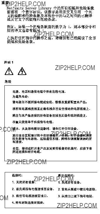
Important safety information
Be sure to read all caution and danger statements in this book before performing any of the instructions.
Leia todas as instru????es de cuidado e perigo antes de exec- utar qualquer opera????o.
Prenez connaissance de toutes les consignes de type Attention et
Danger avant de proc??der aux op??rations d??crites par les instructions.
Lesen Sie alle Sicherheitshinweise, bevor Sie eine Anweisung ausf??hren.
Accertarsi di leggere tutti gli avvisi di attenzione e di pericolo prima di effettuare qualsiasi operazione.
Lea atentamente todas las declaraciones de precauci??n y peligro ante de llevar a cabo cualquier operaci??n.
Online support
Use the World Wide Web (WWW) to download Diagnostic, BIOS Fl;ash, and Device Driver files.
File download address is:
http://www.us.pc.ibm.com/files.html
IBM online addresses
The HMM manuals online address is:
http://www.us.pc.ibm.com/cdt/hmm.html
The IBM PC Company Support Page is:
http://www.us.pc.ibm.com/support/index.html
The IBM PC Company Home Page is:
http://www.pc.ibm.com
iv Netfinity 3500-M20 ??? Type 8657 Models 21Y, 22Y, 31Y, 32Y,
vi Library Name Here Book title here
viii Library Name Here Book title here

General checkout
The server diagnostic programs are stored in upgradable read-only memory (ROM) on the system board. These pro- grams are the primary method of testing the major compo- nents of the server: the system board, Ethernet controller, video controller, RAM, keyboard, mouse (pointing device), diskette drive, serial ports, hard drives, and parallel port. You can also use them to test some external devices. See ???Diagnostic programs and error messages??? on page 10.
Also, if you cannot determine whether a problem is caused by the hardware or by the software, you can run the diag- nostic programs to confirm that the hardware is working properly.
When you run the diagnostic programs, a single problem might cause several error messages. When this occurs, work to correct the cause of the first error message. After the cause of the first error message is corrected, the other error messages might not occur the next time you run the test.
A failed system might be part of a shared DASD cluster (two or more systems sharing the same external storage device(s)). Prior to running diagnostics, verify that the failing system is not part of a shared DASD cluster.
A system might be part of a cluster if:
???The customer identifies the system as part of a cluster.
???One or more external storage units are attached to the system and at least one of the attached storage units is additionally attached to another system or unidentifi- able source.
???One or more systems are located near the failing sys- tem.
If the failing system is suspected to be part of a shared DASD cluster, all diagnostic tests can be run except diag- nostic tests which test the storage unit (DASD residing in the storage unit) or the storage adapter attached to the storage unit.
Notes:
1.For systems that are part of a shared DASD cluster, run one test at a time in looped mode. Do not run all tests in looped mode, as this could enable the DASD diag- nostic tests.
2.If multiple error codes are displayed, diagnose the first error code displayed.
3.If the computer hangs with a POST error, go to the ???Symptom-to-FRU index??? on page 129.
4.If the computer hangs and no error is displayed, go to ???Undetermined problems??? on page 147.
5.Power supply problems, see ???Symptom-to-FRU index??? on page 129.
6.Safety information, see ???Safety information??? on page 155.
2 Netfinity 3500-M20 ??? Type 8657 Models 21Y, 22Y, 31Y, 32Y,

General information
The IBM?? Netfinity?? 3500-M20 server delivers great value for entry server applications. It is ideally suited for network- ing environments that require superior microprocessor per- formance, efficient memory management, flexibility, and large amounts of reliable data storage.
The IBM 3500-M20 server comes with a three-year limited warranty and 90-Day IBM Start Up Support. If you have access to the World Wide Web, you can obtain up-to-date information about the server model and other IBM server products at the following World Wide Web address: http://www.ibm.com/pc/us/netfinity/
Features and specifications
The following provides a summary of the features and speci- fications for the Netfinity 3500-M20 server.
???Microprocessor:
???Intel?? Pentium?? III microprocessor with MMX??? technology and SIMD extensions
???256 KB of level-2 cache (min.)
???Supports up to two microprocessors
???Memory:
???Standard: 128 MB
???Maximum: 2 GB
???Type: 133 MHz, ECC, SDRAM, Registered DIMMs
???4 dual inline slots
???Drives standard:
???Diskette: 1.44 MB
???CD-ROM: 40X IDE
???Hard disk drive (some models)
???Expansion bays:
???Two 5.25-in. bays (1 CD ROM drive installed)
???Two 3.5-in. bays (1 diskette drive installed)
???Three 3.5" slim high bays available (some models have a hard disk drive installed)
???PCI expansion slots:
???Three 33 MHz/64-bit
???Two 33 MHz/32-bit
???Power supply:
???One 330 W (115-230 V ac)
???Video:
???S3 video controller (integrated on system board)
???Compatible with SVGA and VGA
???8 MB SDRAM video memory
???Size
???Height: 492 mm (19.4 in.)
???Depth: 460 mm (18.1 in.)
???Width: 200 mm (7.9 in.)

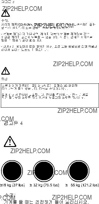
???Weight: approximately 20.9 Kg (46 lb.) when fully configured or 16.8 Kg (37 lb.) minimum.
???Integrated functions:
???Ultra160 SCSI controller
???One 10BASE-T/100BASE-TX Intel Ethernet con- troller on the system board
???Two serial ports
???Parallel port
???Two Universal Serial Bus (USB) ports
???Keyboard port
???Mouse port
???IDE controller port
???Video port
???Acoustical noise emissions:
???Sound power, idling: 5.9 bel maximum
???Environment:
???Air temperature:
???Server on: 10?? to 35?? C (50.0?? to 95.0?? F).
Altitude: 0 to 914 m (2998.7 ft.)
???Server on: 10?? to 32?? C (50.0?? to 89.6?? F).
Altitude: 914 m (2998.7 ft.) to 2133 m (6998.0 ft.)
???Server off: 10?? to 43?? C (50.0?? to 109.4?? F).
Maximum altitude: 2133 m (6998.0 ft.)
???Humidity:
???Server on: 8% to 80%
???Server off: 8% to 80%
???Heat output:
Approximate heat output in British Thermal Units (BTU) per hour
???Minimum configuration: 341 BTU (100 watts)
???Maximum configuration: 1604 BTU (470 watts)
???Electrical input:
???Sine-wave input (50-60 Hz) required
???Input voltage low range:
???Minimum: 100 V ac
???Maximum: 127 V ac
???Input voltage high range:
???Minimum: 200 V ac
???Maximum: 240 V ac
???Input kilovolt-amperes (kVA) approximately:
???Minimum: 0.08 kVA
???Maximum: 0.52 kVA
Server features
The unique design of the server takes advantage of advancements in symmetric multiprocessing (SMP), data storage, and memory management. The server combines:
???Impressive performance using an innovative approach to SMP
4 Netfinity 3500-M20 ??? Type 8657 Models 21Y, 22Y, 31Y, 32Y,

The server supports up to two Pentium III microproces- sors. The server comes with at least one processor installed; you can install an additional processor to enhance performance and provide SMP capability.
???Large system memory
The memory bus in the server supports up to 2gigabytes (GB) of system memory. The memory con- troller provides error correcting code (ECC) support for up to four industry standard PC133, 3.3 V, 168-pin, 8- byte, registered, synchronous-dynamic-random access memory (SDRAM) dual inline memory modules (DIMMs).
???System-management capabilities
The Netfinity Manager software provided on the Serv- erGuide CDs enables you to manage the functions of the server locally and remotely. See ???Netfinity Man- ager??? on page 75 for more information.
???Integrated network environment support
The server comes with an Ethernet controller on the system board. This Ethernet controller has an interface for connecting to 10-Mbps or 100-Mbps networks. The server automatically selects between 10BASE-T and 100BASE-TX environments. The controller provides full-duplex (FDX) capability, which enables simulta- neous transmission and reception of data on the Ether- net local area network (LAN).
???IBM ServerGuide CDs
The ServerGuide CDs included with IBM Netfinity serv- ers provide programs to help you set up the server and install the network operating system (NOS). The Serv- erGuide program detects the hardware options that are installed, and provides the correct configuration pro- gram and device drivers. In addition, the ServerGuide CDs include a variety of application programs for the server.
Reliability, availability, and serviceability
Three of the most important features in server design are reliability, availability, and serviceability (RAS). These fac- tors help to ensure the integrity of the data stored on the server; that the server is available when you want to use it; and that should a failure occur, you can easily diagnose and repair the failure with minimal inconvenience.
The following is an abbreviated list of the RAS features that the server supports.
???Menu-driven setup, system configuration, RAID config- uration, and diagnostic programs
???Power-on self-test (POST)
???Error codes and messages
???Upgradable BIOS and diagnostics
???Automatic restart after a power failure
???CRC checking on the SCSI buses
???Error checking and correcting (ECC) memory
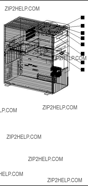
Server controls and indicators
 Socket7


??1?? Power control button: Press this button to manually turn the server on or off.
??2?? Power-on light: This status indicator lights when you turn on the server.
??3?? Hard disk drive light: When this light is on, it indi- cates that the hard disk drive is in use.
??4?? LAN activity light: When this light blinks, it indicates that the integrated Ethernet controller in the server is transmitting or receiving data.
??5?? CD-ROM drive eject button: Push this button to release a CD from the drive.
??6?? CD-ROM drive activity light: When this light is on, it indicates that the CD-ROM drive is in use.
??7?? Diskette eject button: Push this button to release a diskette from the drive.
??8?? Diskette-drive activity light: When this light is on, it indicates that the diskette drive is in use.
Start the server
After you plug the power cord of the server into the power supply and an electrical outlet, the server can start in several ways:
???You can press the Power control button on the front of the server to start the server.
???If the server is turned on and a power failure occurs, the server will start automatically when power is restored.
6 Netfinity 3500-M20 ??? Type 8657 Models 21Y, 22Y, 31Y, 32Y,

CAUTION:
The power control button on the device and/or the power supply do not turn off the electrical current sup- plied to the device. The device also might have more than one power cord. To remove all electrical current from the device, ensure that all power cords are discon- nected from the power source.
2 

 1
1 


You can turn off the server in the following ways:
???Press the Power control button on the top of the server. This starts an orderly shutdown of the operating sys- tem, if this feature is supported by the operating sys- tem, and places the server in standby mode.
Note: After turning off the server, wait at least 5 sec- onds before you press the Power control button to power the server on again.
???Press and hold the Power control button for more than 4 seconds to cause an immediate shutdown of the server and place the server in standby mode. You can use this feature if the operating system ceases to func- tion.
???Disconnect the server power cords from the electrical outlets to shut off all power to the server.
Note: Wait about 15 seconds after disconnecting the power cords for the system to stop running.
8 Netfinity 3500-M20 ??? Type 8657 Models 21Y, 22Y, 31Y, 32Y,

Diagnostics
This section provides basic troubleshooting information to help you resolve some common problems that might occur with the server.
If you cannot locate and correct the problem using the infor- mation in this section, refer to ???Symptom-to-FRU index??? on page 129 for more information.
Diagnostic tools overview
The following tools are available to help you identify and resolve hardware-related problems:
???POST beep codes, error messages, and error logs
The power-on self-test (POST) generates beep codes and messages to indicate successful test completion or the detection of a problem. See ???POST??? for more infor- mation.
???Diagnostic programs and error messages
The server diagnostic programs are stored in upgrad- able read-only memory (ROM) on the system board. These programs are the primary method of testing the major components of the server. See ???Diagnostic pro- grams and error messages??? on page 10 for more infor- mation.
POST
When you turn on the server, it performs a series of tests to check the operation of server components and some of the options installed in the server. This series of tests is called the power-on self-test or POST.
If POST finishes without detecting any problems, a single beep sounds and the first screen of the operating system or application program appears.
If POST detects a problem, more than one beep sounds and an error message appears on the screen. See ???POST beep codes??? and ???POST error messages??? on page 10 for more information.
Notes:
1.If you have a power-on password set, you must type the password and press Enter, when prompted, before POST will continue.
2.A single problem might cause several error mes- sages. When this occurs, work to correct the cause of the first error message. After you correct the cause of the first error message, the other error messages usu- ally will not occur the next time you run the test.
POST beep codes
POST generates beep codes to indicate successful comple- tion or the detection of a problem.

???One beep indicates the successful completion of POST.
???More than one beep indicates that POST detected a problem. For more information, see ???Beep symptoms??? on page 129.
POST error messages
POST error messages occur during startup when POST finds a problem with the hardware or detects a change in the hardware configuration. For a list of POST errors, see ???POST error codes??? on page 141.
Error logs
The POST error log contains the three most recent error codes and messages that the system generated during POST.
To view the contents of the error log, start the Configura- tion/Setup Utility program (see ???Starting the Configura- tion/Setup Utility program??? on page 33); then, select Error Logs from the main menu.
Diagnostic programs and error messages
The server diagnostic programs are stored in upgradable read-only memory (ROM) on the system board. These pro- grams are the primary method of testing the major compo- nents of the server.
Diagnostic error messages indicate that a problem exists; they are not intended to be used to identify a failing part. Troubleshooting and servicing of complex problems that are indicated by error messages should be performed by trained service personnel.
Sometimes the first error to occur causes additional errors. In this case, the server displays more than one error mes- sage. Always follow the suggested action instructions for the first error message that appears.
The following sections contain the error codes that might appear in the detailed test log and summary log when run- ning the diagnostic programs.
The error code format is as follows:
fff-ttt-iii-date-cc-text message
where:
fffis the three-digit function code that indicates the function being tested when the error occurred. For example, function code 089 is for the microprocessor.
tttis the three-digit failure code that indicates the exact test failure that was encountered.
10 Netfinity 3500-M20 ??? Type 8657 Models 21Y, 22Y, 31Y, 32Y,
ccis the check digit that is used to verify the validity of the information.
text message is the diagnostic message that indicates the reason for the problem.
Text messages
The diagnostic text message format is as follows:
Function Name: Result (test specific string)
where:
Function Name is the name of the function being tested when the error occurred. This corresponds to the function code (fff) given in the previous list.
during the diagnostic test, such as when a device that is to be tested is not installed.
Test Specific String This is additional information that you can use to analyze the problem.
Starting the diagnostic programs
You can press F1 while running the diagnostic programs to obtain Help information. You also can press F1 from within a help screen to obtain online documentation from which you can select different categories. To exit Help and return to where you left off, press Esc.
To start the diagnostic programs:
1.Turn on the server and watch the screen.
2.When the message F2 for Diagnostics appears, press F2.
3.Type in the appropriate password; then, press Enter.
4.Select either Extended or Basic from the top of the screen.
5.When the Diagnostic Programs screen appears, select the test you want to run from the list that appears; then, follow the instructions on the screen.
Notes:
a.If the server stops during testing and you cannot continue, restart the server and try running the diagnostic programs again.
b.The keyboard and mouse (pointing device) tests assume that a keyboard and mouse are attached to the server.
c.If you run the diagnostic programs with no mouse attached to the server, you will not be able to navi- gate between test categories using the Next Cat and Prev Cat buttons. All other functions pro- vided by mouse-selectable buttons are also avail- able using the function keys.
d.You can test the USB keyboard by using the regu- lar keyboard test. The regular mouse test can test a USB mouse. Also, you can run the USB hub test only if there are no USB devices attached.
e.You can view server configuration information (such as system configuration, memory contents, interrupt request (IRQ) use, direct memory access (DMA) use, device drivers, and so on) by selecting Hardware Info from the top of the screen.
When the tests have completed, you can view the Test Log by selecting Utility from the top of the screen.
If the hardware checks out OK but the problem persists dur- ing normal server operations, a software error might be the cause. If you suspect a software problem, refer to the infor- mation that comes with the software package.
Viewing the test log
The test log will not contain any information until after the diagnostic program has run.
Note: If you already are running the diagnostic programs, begin with step 3.
To view the test log:
1.Turn on the server and watch the screen.
If the server is on, shut down the operating system and restart the server.
2.When the message F2 for Diagnostics appears, press F2.
If a power-on password is set, the server prompts you for it. Type in the appropriate password; then, press Enter.
3.When the Diagnostic Programs screen appears, select Utility from the top of the screen.
4.Select View Test Log from the list that appears; then, follow the instructions on the screen.
12 Netfinity 3500-M20 ??? Type 8657 Models 21Y, 22Y, 31Y, 32Y,

The system maintains the test-log data while the server is powered on. When you turn off the power to the server, the test log is cleared.
Diagnostic error message tables
For descriptions of the error messages that might appear when you run the diagnostic programs, see ???Diagnostic error codes??? on page 133. If diagnostic error messages appear that are not listed in those tables, make sure that the server has the latest levels of BIOS, Advanced System Manage- ment Processor, ServeRAID, and diagnostics microcode installed.
Power checkout
Power problems can be difficult to troubleshoot. For instance, a short circuit can exist anywhere on any of the power distribution busses. Usually a short circuit will cause the power subsystem to shut down because of an overcur- rent condition.
A general procedure for troubleshooting power problems is as follows:
1.Power off the system and disconnect the AC cord(s).
2.Check for loose cables in the power subsystem. Also check for short circuits, for instance if there is a loose screw causing a short circuit on a circuit board.
3.Remove adapters and disconnect the cables and power connectors to all internal and external devices until system is at minimum configuration required for power on (see "Minimum operating requirements" on page 148).
4.Reconnect the AC cord and power on the system. If the system powers up successfully, replace adapters and devices one at a time until the problem is isolated. If system does not power up from minimal configura- tion, replace FRUs of minimal configuration one at a time until the problem is isolated.
To use this method it is important to know the minimum con- figuration required for a system to power up (see page 148).
Recovering BIOS
If the BIOS code in the server has become corrupted, such as from a power failure during a flash update, you can recover the BIOS using the Flash ROM Page-Swap Jumper (J38) and a BIOS flash diskette.
Note: You can obtain a BIOS flash diskette from one of the following sources:
???Use the ServerGuide program to make a BIOS flash diskette.
???Download a BIOS flash diskette from the World Wide Web. Go to http://www.pc.ibm.com/sup- port/, select IBM Server Support, and make the selections for the server.

The flash memory of the server consists of a primary page and a backup page. The J38 jumper controls which page is used to start the server. If the BIOS in the primary page is corrupted, you can use the backup page to start the server; then boot the BIOS Flash Diskette to restore the BIOS to the primary page.
To recover the BIOS:
1.Turn off the server and peripheral devices and discon- nect all external cables and power cords; then, remove the cover.
2.Locate jumper J38 on the processor board (see ???Sys- tem board switches and jumpers??? on page 42). The jumper consists of three pins, two of which are covered by a jumper.
3.Move the J38 jumper from its current location to con- nect the center pin and the pin on the opposite end of the connector block, as shown in the following diagram:
4.Insert the BIOS flash diskette into the diskette drive.
5.Restart the server.
6.The system begins the power-on self-test (POST). Select 1 ??? Update POST/BIOS from the menu that con- tains various flash (update) options.
7.When you are asked whether you want to save the cur- rent code to a diskette, type N.
8.You will be asked to choose which language you wish to use. Select your language (0-7) and press Enter to accept your choice.
9.Do not reboot the system at this time.
10.Remove the BIOS Flash Diskette from the diskette drive.
11.Power-off the server.
12.Move jumper J38 back to its original setting to return to normal startup mode.
13.Restart the server. The system should start up nor- mally.
Replacing the battery
IBM has designed this product with your safety in mind. The lithium battery must be handled correctly to avoid possible
14 Netfinity 3500-M20 ??? Type 8657 Models 21Y, 22Y, 31Y, 32Y,
danger. If you replace the battery, you must adhere to the following instructions.
CAUTION:
When replacing the battery, use only IBM Part Number 33F8354 or an equivalent type battery recommended by the manufacturer. If your system has a module contain- ing a lithium battery, replace it only with the same mod- ule type made by the same manufacturer. The battery contains lithium and can explode if not properly used, handled, or disposed of.
Do not:
???Throw or immerse into water
???Heat to more than 100??C (212??F)
???Repair or disassemble
Dispose of the battery as required by local ordinances or regulations.
Note: In the U.S., call 1-800-IBM-4333 for information about battery disposal.
If you replace the original lithium battery with a heavy-metal battery or a battery with heavy-metal components, be aware of the following environmental consideration. Batteries and accumulators that contain heavy metals must not be dis- posed of with normal domestic waste. They will be taken back free of charge by the manufacturer, distributor, or rep- resentative, to be recycled or disposed of in a proper man- ner.
Note: After you replace the battery, you must reconfigure the server and reset the system date and time.
To replace the battery:
1.Read the information in ???Before you begin??? on page 43.
2.Follow any special handling and installation instructions supplied with the battery.
3.Turn off the server and all attached devices and discon- nect all external cables and power cords (see ???Safety information??? on page 155); then remove the top cover.
4.Locate the battery on the system board (see ???System board component locations??? on page 39).
5.Remove adapters as necessary so you can access the battery. (See ???Working with adapters??? on page 45.)
6.Remove the battery:
a.Use one finger to lift the battery clip over the bat- tery.
b.Use one finger to slightly slide the battery toward the rear of the server. The spring mechanism behind the battery will push it out toward you as you slide it forward.
c.Use your thumb and index finger to pull the bat- tery from under the battery clip.
d.Ensure that the battery clip is touching the base of the battery socket by pressing gently on the clip.

7.Insert the new battery:
a.Tilt the battery so that you can insert it into the front of the socket, under the battery clip.
b.As you slide it under the battery clip, press the battery down into the socket.
8.Reinstall any adapters that you removed.
9.Reinstall the top cover.
Note: You must wait approximately 20 seconds after you plug the power cord of the server into an electrical outlet before the power control button becomes active.
10.Start the Configuration/Setup Utility program and set configuration parameters as needed. Refer to ???Using the Configuration/Setup Utility program??? on page 33.
Temperature checkout
Proper cooling of the system is important for proper opera- tion and system reliability. For a typical Netfinity server, you should make sure:
???Each of the drive bays has either a drive or a filler panel installed
???The top cover is in place during normal operation
???There is at least 50 mm (2 inches) of ventilated space at the sides of the server and 100 mm (4 inches) at the rear of the server
???The top cover is removed for no longer than 30 minutes while the server is operating
???Cables for optional adapters are routed according to the instructions provided with the adapters (ensure that cables are not restricting air flow)
???The fans are operating correctly and the air flow is good
???A failed fan is replaced within 1 hour.
16 Netfinity 3500-M20 ??? Type 8657 Models 21Y, 22Y, 31Y, 32Y,

In addition, ensure that the environmental specifications for the system are met. See ???Features and specifications??? on page 3.
Diagnosing errors
To find solutions to problems that have definite symptoms, see ???Error symptoms??? on page 138.
If you cannot find the problem there, go to ???Starting the diag- nostic programs??? on page 11 to test the server.
If you have just added new software or a new option and the server is not working, do the following before using the error symptoms table:
???Remove the software or device that you just added.
???Run the diagnostic tests to determine if the server is running correctly.
???Reinstall the new software or new device.
Troubleshooting the Ethernet controller
This section provides troubleshooting information for prob- lems that might occur with the 10/100 Mbps Ethernet con- troller.
Network connection problems
If the Ethernet controller cannot connect to the network, check the following:
???Make sure that the cable is installed correctly.
The network cable must be securely attached at all connections. If the cable is attached but the problem persists, try a different cable.
If you set the Ethernet controller to operate at 100 Mbps, you must use Category 5 cabling.
If you directly connect two workstations (without a hub), or if you are not using a hub with X ports, use a cross- over cable.
Note: To determine whether a hub has an X port, check the port label. If the label contains an X, the hub has an X port.
???Determine if the hub supports auto-negotiation. If not, try configuring the integrated Ethernet controller manu- ally to match the speed and duplex mode of the hub.
???Check the Ethernet controller lights on the operator information panel.
These lights indicate whether a problem exists with the connector, cable, or hub.
???The Ethernet Link Status light illuminates when the Ethernet controller receives a LINK pulse from the hub. If the light is off, there might be a defec- tive connector or cable, or a problem with the hub.
???The Ethernet Transmit/Receive Activity light illumi- nates when the Ethernet controller sends or receives data over the Ethernet Network. If the Ethernet Transmit/Receive Activity light is off,
make sure that the hub and network are operating and that the correct device drivers are loaded.
???The Ethernet Speed 100 Mbps light illuminates when the Ethernet controller LAN speed is 100 Mbps.
???Make sure that you are using the correct device drivers, supplied with the server.
???Check for operating system-specific causes for the problem.
???Make sure that the device drivers on the client and server are using the same protocol.
???Test the Ethernet controller.
How you test the Ethernet controller depends on which operating system you are using (see the Ethernet con- troller device driver README file).
Ethernet controller troubleshooting chart
You can use the following troubleshooting chart to find solu- tions to 10/100 Mbps Ethernet controller problems that have definite symptoms.
Table 1. Ethernet troubleshooting chart
18 Netfinity 3500-M20 ??? Type 8657 Models 21Y, 22Y, 31Y, 32Y,
Table 1. Ethernet troubleshooting chart
Table 1. Ethernet troubleshooting chart
Ethernet controller messages
The integrated Ethernet controller might display messages from the following device drivers:
???Novell??? NetWare??? or IntraNetWare Server ODI
???NDIS Adapter for level 2.01 (OS/2)
???NDIS Adapter for level 4.0 (Windows NT)
???SCO??? UNIX LLI
Novell NetWare or IntraNetWare server ODI driver messages
This section provides explanations of the error messages for the Novell NetWare or IntraNetWare server ODI driver, and suggested actions to resolve each problem.
20 Netfinity 3500-M20 ??? Type 8657 Models 21Y, 22Y, 31Y, 32Y,
Table 2. Novell NetWare or IntraNetWare ODI driver messages for the Ethernet controller

Table 2. Novell NetWare or IntraNetWare ODI driver messages for the Ethernet controller
PCNTNW- A resource tag is unavailable.
NW-072
Explanation: The driver tried to allocate some resources that were not available. Action: Add more memory, or free some memory resources in the server. Then, restart the server.
PCNTNW- Unable to allocate memory NW-073
Explanation: The driver failed to allocate the memory needed for normal operation. Action: Add more memory, or free some memory resources in the server. Then, restart the server.
PCNTNW- The hardware interrupt cannot be set. NW-074
Explanation: An attempt was made to initialize a given hardware interrupt. The attempt was not successful.
Action: Verify that the Ethernet controller is enabled. If the Ethernet controller is enabled, go to ???Starting the diagnostic programs??? on page 11 to run the diagnostic programs. If you have an Ethernet adapter installed, make sure that the adapter does not share an IRQ with any other device.
PCNTNW- The Multiple Link Interface Driver NW-075 (MLID) cannot be registered with the
Link Support Layer (LSL).
Explanation: An error occurred while the driver was trying to register with the LSL. Action: Check the version of the NetWare or IntraNetWare Operating System. Make sure that this driver is correct for the version of NetWare or IntraNetWare that you are using. Restart the server.
PCNTNW- The Multiple Link Interface Driver NW-079 (MLID) did not initialize MSMTx Free
Count.
Explanation: The MSMTx Free Count is not initialized correctly.
Action: Restart the server. If the problem persists, go to ???Starting the diagnostic programs??? on page 11 to run the diagnostic programs.
22 Netfinity 3500-M20 ??? Type 8657 Models 21Y, 22Y, 31Y, 32Y,
Table 2. Novell NetWare or IntraNetWare ODI driver messages for the Ethernet controller

Table 2. Novell NetWare or IntraNetWare ODI driver messages for the Ethernet controller
PCNTNW- The local bit in the node address NW-127 override was set.
Explanation: The local bit in the IEEE address format indicates that the addresses are being managed locally. If you use the node address override capabilities of this driver to enter a new address, the local bit must be set. You entered an address without the local bit set. The driver has set the local bit. Action: None necessary, message is for information only.
PCNTNW- The device was not found.
NW-164
Explanation: The driver cannot find an Ethernet controller in the server.
Action: Verify that the Ethernet controller is enabled. If the Ethernet controller is enabled, go to ???Starting the diagnostic programs??? on page 11 to run the diagnostic programs.
PCNTNW- The device was not found at NW-165 IOADDRESS.
Explanation: The Ethernet controller cannot be found at the I/O address specified.
Action: The Ethernet controller does not require a parameter for the I/O address. Remove the I/O address parameter.
PCNTNW- PCI scan specified, device not found. NW-167
Explanation: The driver cannot locate the Ethernet controller on the PCI bus. Action: Verify that the Ethernet controller is enabled. If the problem persists, go to ???Starting the diagnostic programs??? on page 11 to run the diagnostic programs.
PCNTNW- The DMA parameter is not necessary NW-180 for PCI device.
Explanation: The Ethernet controller does not require a DMA setting.
Action: None necessary, message is for information only.
Network driver interface specification 2.01 (OS/2) driver messages
This section provides explanations of the error messages for the NDIS 2.01 (OS/2) drivers, and suggested actions to resolve each problem.
24 Netfinity 3500-M20 ??? Type 8657 Models 21Y, 22Y, 31Y, 32Y,
Table 3. NDIS 2.01 (OS/2) driver messages for the Ethernet controller
PCNTND-1 Unable to open the Protocol Manager.
Explanation: The NDIS stack is not configured correctly.
Action: Check and correct the configuration.
PCNTND-6 Out of memory while allocating buffers.
Explanation: The driver could not allocate the requested buffers.
Action: Check the system configuration. Edit the PROTOCOL.INI file to reduce the number of Txbuffers and Rxbuffers specified for the driver.
PCNTND-7 A Protocol Manager device error occurred.
Explanation: The NDIS stack is not configured correctly.
Action: Check and correct the configuration.
PCNTND-8 Bad status for the Protocol Manager.
Explanation: The NDIS stack is not configured correctly in the PROTOCOL.INI file.
Action: Check and correct the configuration.
PCNTND-9 Cannot find the PROTOCOL.INI entry.
Explanation: The NDIS stack is not configured correctly in the PROTOCOL.INI file.
Action: Check and correct the configuration.
PCNTND-10 The Protocol Manager Input Output
Control (IOCTL) failed.
Explanation: The NDIS stack is not configured correctly in the PROTOCOL.INI file.
Action: Check and correct the configuration.
PCNTND-11 Protocol Manager registration failed.
Explanation: The NDIS stack is not configured correctly.
Action: Check and correct the configuration.

Table 3. NDIS 2.01 (OS/2) driver messages for the Ethernet controller
PCNTND-15 Device not found.
Explanation: The driver cannot find an Ethernet controller in the server.
Action: Verify that the Ethernet controller is enabled. If the Ethernet controller is enabled, go to ???Starting the diagnostic programs??? on page 11 to run the diagnostic programs.
PCNTND-16 PCI scan specified, device not found.
Explanation: The driver cannot locate the Ethernet controller on the PCI bus. Action: Verify that the Ethernet controller is enabled. If the Ethernet controller is enabled, go to ???Starting the diagnostic programs??? on page 11 to run the diagnostic programs.
PCNTND-21 The adapter failed the checksum test.
Explanation: The driver cannot find an Ethernet controller.
Action: Verify that the Ethernet controller is enabled. If the Ethernet controller is enabled, go to ???Starting the diagnostic programs??? on page 11 to run the diagnostic programs.
PCNTND-23 WARNING: PCNET IRQ found = xx
Explanation: The interrupt request (IRQ) setting (xx) in the PROTOCOL.INI file does not match the hardware IRQ setting. Action: Remove the IRQ setting from the PROTOCOL.INI file or change the IRQ setting in the PROTOCOL.INI file to match the IRQ setting shown in the PCI Slot/Device Information selection of the Advanced Setup menu in the Configuration/Setup Utility program.
PCNTND-24 WARNING: PCNET IRQ does not match PROTOCOL.INI.
Explanation: The interrupt request (IRQ) setting in the PROTOCOL.INI file does not match the hardware IRQ setting. Action: Remove the IRQ setting from the PROTOCOL.INI file or change the IRQ setting in the PROTOCOL.INI file to match the IRQ setting shown in the PCI Slot/Device Information selection of the Advanced Setup menu in the Configuration/Setup Utility program.
26 Netfinity 3500-M20 ??? Type 8657 Models 21Y, 22Y, 31Y, 32Y,
Table 3. NDIS 2.01 (OS/2) driver messages for the Ethernet controller
PCNTND-25 PCI scan specified, PCI bus not found!
Explanation: The driver cannot locate the PCI bus.
Action: Run the diagnostic programs.
PCNTND-29 WARNING: DMA number is not necessary for PCI device.
Explanation: The Ethernet controller does not require a DMA setting. Action: Remove the DMA setting in the PROTOCOL.INI file.
PCNTND-33 PCNET device with specified IOBASE is already in use.
Explanation: The specified I/O address number is already in use by another Ethernet controller or device.
Action: Remove the I/O address setting in the PROTOCOL.INI file.
NDIS 4.0 (Windows NT) driver messages
This section contains the error messages for the NDIS 4.0 drivers. The explanation and recommended action are included with each message.
Table 4. NDIS (Windows NT) driver messages for the Ethernet controller
PermaNet??? No Secondary Adapter Found.
Server: Grouping Mode is disabled.
Explanation: The failover option requires an adapter that is compatible with the device driver of the Ethernet controller on the system board. No such adapter was found.
Action: Make sure the correct adapter is installed.
PermaNet Problem Occurs on the Primary Server: Adapter. Switching over to the
Secondary Adapter.
Explanation: The system detected a problem with the primary Ethernet connection and has transferred all network traffic to the secondary Ethernet controller. Action: identify the cause of the failure on the primary Ethernet connection. Restoring the operational state of the primary connection will cause the network traffic to automatically transfer to the primary Ethernet controller.
Table 4. NDIS (Windows NT) driver messages for the Ethernet controller
PermaNet Switching back to Primary Adapter.
Server:
Explanation: The primary Ethernet connection is now operating correctly. Network traffic will automatically transfer to the primary Ethernet controller. Action: None needed, message is for information only.
UNIX messages
This section provides descriptions of the Ethernet error mes- sages for the SCO UNIX LLI driver, and suggested actions to resolve each problem.
Table 5. UNIX LLI driver messages for the Ethernet controller
pnt0-2 PCI search specified, PCI device not found!
Explanation: The driver cannot locate the
Ethernet controller on the PCI bus.
Action:
???Run the NETCONFIG program to search for another Ethernet controller
???Verify that the Ethernet controller is enabled. If the Ethernet controller is enabled, run the diagnostic programs.
pnt0-6 Cannot allocate memory for the adapter during an interrupt. Please check the Streams parameters.
Explanation: On a SunSoft Solaris system, this message indicates that the system is out of Streams memory blocks.
Action: Use the CRASH utility to increase the number of Streams memory blocks. Modify the interrupt request (IRQ) settings in the Configuration/Setup Utility program, or run the NETCONFIG program to match the hardware settings.
pnt0-7 Cannot allocate memory for the adapter during reset. Please check the Streams parameters.
Explanation: The system is out of Streams memory blocks.
Action: Use the CRASH utility to increase the number of Streams memory blocks.
28 Netfinity 3500-M20 ??? Type 8657 Models 21Y, 22Y, 31Y, 32Y,
Table 5. UNIX LLI driver messages for the Ethernet controller
pnt0-11 Device not found!
Explanation: The driver cannot find an Ethernet controller.
Action: Verify that the Ethernet controller is enabled. If the Ethernet controller is enabled, run the diagnostic programs.
pnt0-12 Device failed checksum test!
Explanation: The driver cannot find an Ethernet controller.
Action: Verify that the Ethernet controller is enabled. If the Ethernet controller is enabled, run the diagnostic programs.
pnt0-13 add_intr_handler failed! Interrupts already enabled.
Explanation: The interrupt request (IRQ) that was specified, or the IRQ that was found, conflicts with other devices in the server. Action: Modify the hardware settings.
pnt0-14 Cannot locate hardware.
Explanation: The SunSoft Solaris driver cannot find any Ethernet controller.
Action: Verify that the Ethernet controller is enabled. If the Ethernet controller is enabled, run the diagnostic programs.
pnt0-15 No more devices to open.
Explanation: The SunSoft Solaris driver cannot find any more Ethernet controllers. Action: Verify that additional IBM Netfinity 10/100 Fault Tolerant Adapters are present or replace the Ethernet adapter that fails to respond. If the problem persists, run the diagnostic programs.
pnt0-17 Device fault...Reset initiated!
Explanation: The SunSoft Solaris driver has been reset due to a device fault.
Action: Verify that additional IBM Netfinity 10/100 Fault Tolerant Adapters are present or replace the Ethernet adapter that fails to respond. If the problem persists, run the diagnostic programs.

Table 5. UNIX LLI driver messages for the Ethernet controller
pnt0-19 IRQ found for PCnet hardware does not match space.c (or pnt.conf)!
Explanation: This is a warning message referring to the interrupt request (IRQ) that the SunSoft Solaris driver found in the system. Action: Ignore this message if you are sure that this is what you want to do. Otherwise, run the NETCONFIG program to match the hardware settings
pnt0-20 add_intr_handler failed! Unknown interrupt type.
Explanation: The interrupt request (IRQ) that was specified, or the IRQ that was found, conflicts with other devices in the server.
Action:
???Modify the hardware settings.
???Run the NETCONFIG program to search for another Ethernet controller.
pnt0-21 add_intr_handler failed! Out of range interrupt number.
Explanation: The interrupt request (IRQ) that was specified, or the IRQ that was found, conflicts with other devices in the server.
Action:
???Modify the hardware settings.
???Run the NETCONFIG program to search for another Ethernet controller.
pnt0-22 add_intr_handler failed! Out of range IPL.
Explanation: The interrupt request (IRQ) that was specified, or the IRQ that was found, conflicts with other devices in the server. Action: Modify the hardware settings. Run the NETCONFIG program to search for another Ethernet controller.
pnt0-23 add_intr_handler failed! Vector already occupied.
Explanation: The interrupt request (IRQ) that was specified, or the IRQ that was found, conflicts with other devices in the server. Action: Modify the hardware settings.
30 Netfinity 3500-M20 ??? Type 8657 Models 21Y, 22Y, 31Y, 32Y,
Table 5. UNIX LLI driver messages for the Ethernet controller
pnt0-24 add_intr_handler failed! Vector already shared at different IPL.
Explanation: The interrupt request (IRQ) that was specified, or the IRQ that was found, conflicts with other devices in the server.
Action:
???Modify the hardware settings.
???Run the NETCONFIG program to search for another Ethernet controller.
pnt0-26 The DMA number is not necessary for PCI device.
Explanation: The IBM Netfinity 10/100 Fault Tolerant Adapter does not require a DMA setting.
Action: Edit the SPACE.C file to delete the DMA parameter.
pnt0-29 The IRQ number is already in use.
Explanation: The specified I/O address is already in use.
Action: Run the NETCONFIG program to modify the hardware settings.
pnt0-31 I/O address is not necessary for the PCI device.
Explanation: The I/O address specified is not required.
Action: Remove the assigned I/O address specified for the Ethernet controller.
32 Netfinity 3500-M20 ??? Type 8657 Models 21Y, 22Y, 31Y, 32Y,

Configuring the server
The following configuration programs are provided with the server:
???Configuration/Setup Utility
The Configuration/Setup Utility program is part of the basic input/output system (BIOS) code that comes with the server. You can use this program to configure serial and parallel port assignments, change interrupt request (IRQ) settings, change the drive startup sequence, set the date and time, and set passwords. See ???Using the Configuration/Setup Utility program??? for more information.
???SCSISelect Utility
With the built-in SCSISelect Utility program, you can configure the devices attached to the integrated SCSI controller. Use this program to change default values, resolve configuration conflicts, and perform a low-level format on a SCSI hard disk drive. See ???Using the SCSISelect utility program??? on page 37 for more infor- mation.
???ServerGuide CDs
The ServerGuide CDs include software setup and installation tools specifically designed for IBM Netfinity servers. You can use these CDs during the initial installation of the server to configure the server hard- ware and simplify the network operating system instal- lation. The ServerGuide CDs also contain a collection of application programs, which you can install after the server is up and running.
???ServeRAID programs
The ServeRAID programs come with the optional Serv- eRAID adapters and with server models that have a ServeRAID adapter preinstalled. If a ServeRAID adapter has been installed in the server, you must use the ServeRAID configuration program to define and configure the disk-array subsystem before you install the operating system.
Using the Configuration/Setup Utility program
This section provides the instructions needed to start the Configuration/Setup Utility program and descriptions of the menu choices available.
Starting the Configuration/Setup Utility program
To start the Configuration/Setup Utility program:
1.Turn on the server and watch the monitor screen.
2.When the message Press F1 for Configura- tion/Setup appears, press F1.
3.Follow the instructions that appear on the screen.
Choices available from the Configuration/Setup main menu
From the Configuration/Setup Utility main menu, you can select settings that you want to change. The Configura- tion/Setup Utility main menu is similar to the following:
IBM Netfinity Setup - ?? IBM Corporation 1998
Configuration/Setup Utility
???System Summary
???System Information
???Devices and I/O Ports
???Date and Time
???System Security
???Start Options
???Advanced Setup
???Error Logs
Save Settings Restore Settings Load Default Settings
Exit Setup
Notes:
1.You can press F1 to display Help information for a selected menu item.
2.The choices on some menus might differ slightly, depending on the BIOS version in the server.
Descriptions of the choices available from the main menu are as follows:
???System Summary
Select this choice to display configuration information. This includes the type and speed of the microproces- sors and the amount of memory installed.
Changes that you make to configuration settings appear on this summary screen. You cannot edit the fields.
This choice appears on both the full and limited Config- uration/Setup Utility menus.
???System Information
Select this choice to display information about the server. Changes that you make on other menus might appear on this summary screen. You cannot edit any fields. The System Information choice appears only on the full Configuration/Setup Utility main menu.
???Product Data
Select this choice to view system information, such as the machine type and model, the server serial number, and the revision level or issue date of the BIOS stored in the flash electronically eras- able programmable ROM (EEPROM).
???Devices and I/O Ports
34 Netfinity 3500-M20 ??? Type 8657 Models 21Y, 22Y, 31Y, 32Y,
Select this choice to view or change the assignments for devices and input/output ports. This choice appears only on the full Configuration/Setup Utility main menu.
???Date and Time
Select this choice to set the system date and time.
The system time is in a 24-hour format: hour:minute:second.
???System Security
Select this choice to set a power-on password. See ???Using passwords??? on page 36 for more information.
???Start Options
Select this choice to view or change the start options. Start options take effect when you start the server.
You can select keyboard operating characteristics, such as the keyboard speed. You also can specify whether the keyboard number lock starts on or off. You also can enable the server to run without a diskette drive, monitor, or keyboard.
The server uses a startup sequence to determine the device from which the operating system loads. For example, you can define a startup sequence that checks for a startable diskette in the diskette drive, then checks the hard disk drive in bay 1, and then checks a network adapter.
You also can select which PCI Small Computer System Interface (SCSI) adapter is given boot precedence. The first drive that is attached to the selected adapter will be assigned drive number 80H and the operating system will start from that drive. The default for boot precedence is Disabled. The range of choices depends upon the number of PCI SCSI adapters installed in the server.
You can enable a virus-detection test that checks for changes in the master boot record at startup.
???Advanced Setup
Select this choice to change values for advanced hard- ware features, such as cache control and PCI configu- ration.
A warning message appears above the choices on this menu to alert you that the system might malfunction if these options are configured incorrectly. Follow the instructions on the screen carefully.
???Processor Serial Number Access
Select this choice to identify if the microprocessor serial number in the microprocessor is readable.
???Core Chipset Control
Select this choice to modify settings that control features of the core chip set on the system board.
Attention: Do not make changes here unless directed to do so by an IBM authorized service representative.
???Cache Control
Select this choice to enable or disable the micro- processor cache. In addition, you can define the microprocessor cache type as write-back (WB) or write-through (WT). Selecting write-back mode will provide the maximum system performance.
???PCI Bus Control
Select this choice to assign IRQs and program the master latency timer.
Note: If a memory error is detected during normal operations, System Management Interrupt (SMI) can disable the memory.
???Memory Settings
Select this choice to manually disable or enable a bank of memory.
If a memory error is detected during POST or memory configuration, the server can automati- cally disable the failing memory bank and con- tinue operating with reduced memory capacity. If this occurs, you must manually enable the mem- ory bank after the problem is corrected. Select Memory Settings from the Advanced Setup menu, use the arrow keys to highlight the bank that you want to enable; then, use the arrow keys to select Enable.
???Error Log
Select this choice to view or clear the error log.
???Select POST Error Log to view the three most recent error codes and messages that the system generated during POST.
???Select Clear error logs to clear the error logs.
???Save Settings
Select this choice to save the customized settings.
???Restore Settings
Select this choice to delete the changes and restore the previous settings.
???Load Default Settings
Select this choice to cancel the changes and restore the factory settings.
???Exit Setup
If you have made any changes, the program will prompt you to save the changes or exit without saving the changes.
Using passwords
The System Security choice appears only on the full Con- figuration/Setup Utility menu. After you select this choice, you can implement a power-on password.
Power-on password
After you set a power-on password, you can enable the unattended-start mode. This locks the keyboard and mouse, but allows the server to start the operating system.
36 Netfinity 3500-M20 ??? Type 8657 Models 21Y, 22Y, 31Y, 32Y,

The keyboard and mouse remain locked until you enter the correct password.
You can use any combination of up to seven characters (A??? Z, a???z, and 0???9) for the power-on password. Keep a record of the password in a secure place. If you forget the power- on password, you can regain access to the server through one of the following methods:
???Start the Configuration Setup Utility program and change the power-on password.
???Change the position of the password override switch as described in ???Setting the password override switch???.
???Remove the battery and then install the battery.
Setting the password override switch: When a power-on password is set, POST does not complete until you enter the password. If you forget the power-on pass- word, you can regain access to the server by changing the position of switch 8 on the system board to bypass the power-on password check. You can then start the Configu- ration/Setup Utility program and change the power-on pass- word. For the location of the password override switch, see Table 6 on page 43.
Using the SCSISelect utility program
SCSISelect is a built-in, menu-driven configuration utility program that you can use to:
???View the default SCSI IDs
???Locate and correct configuration conflicts
Note: If the server has a RAID adapter installed, use the configuration method supplied with the RAID adapter to view or change SCSI settings for attached devices.
Starting the SCSISelect utility program
To start the SCSISelect utility program:
1.Turn on the server.
2.When the <<< Press <CTRL><A> for SCSISelect??? Utility! >>> prompt appears, press Ctrl+A.
3.When the Would you like to configure the host adapter or run the SCSI disk utility? question appears, make your selection and press Enter.
4.Use the arrow keys to select a choice from the menu.
???Press Esc to return to the previous menu.
???Press the F5 key to switch between color and monochrome modes (if the monitor permits).
5.Follow the instructions on the screen to change the set- tings of the selected items; then, press Enter.
Choices available from the SCSISelect menu
The following choices appear on the SCSISelect Utility menu:
???Configure/View Host Adapter Settings
Select this choice to view or change the SCSI controller settings. To reset the SCSI controller to its default val- ues, press F6; then, follow the instructions that appear on the screen.
You can view or change the following controller set- tings:
???Host Adapter SCSI ID
Select this choice to view the SCSI controller ID, normally 7.
???SCSI Parity Checking
Select this choice to view the assigned value of
Enabled.
???Host Adapter SCSI Termination
Select this choice to view the assigned value of
Enabled.
???Boot Device Options
Select this choice to configure startable device parameters. Before you can make updates, you must know the ID of the device whose parameters you want to configure.
???SCSI Device Configuration
Select this choice to configure SCSI device parameters. Before you can make updates, you must know the ID of the device whose parameters you want to configure.
Note: The Maximum Sync Transfer Rate repre- sents the transfer rate for Ultra SCSI devices.
???The transfer rate for Ultra3 SCSI LVD devices is 160.0
???The transfer rate for Ultra2 SCSI LVD devices is 80.0
???The transfer rate for Fast SCSI devices is 20.0
???Advanced Configuration Options
Select this choice to view or change the settings for advanced configuration options. These options include enabling support for large hard disk drives and support for drives with UltraSCSI speeds.
???SCSI Disk Utilities
Select this choice to view the SCSI IDs that are assigned to each device or to format a SCSI device.
To use the utility program, select a drive from the list. Read the screens carefully before making a selection.
Note: If you press Ctrl+A before the selected drives are ready, an Unexpected SCSI Command Fail- ure screen might appear. Restart the server and watch the SCSISelect messages as each drive spins up. After the drive that you want to view or format spins up, press Ctrl+A.
38 Netfinity 3500-M20 ??? Type 8657 Models 21Y, 22Y, 31Y, 32Y,
Installing options
This chapter provides instructions to help you add options to the server.
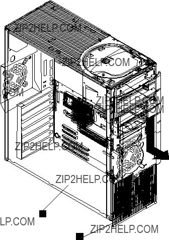
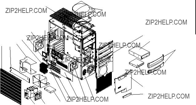
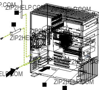
Expanded view of the Netfinity 3500-M20
??1?? Support bracket
??2?? Air baffle
??3?? Microprocessor
??4?? Terminator card
??5?? Filler panel
??6?? Memory module
??7?? Hard disk drive
??8?? Drive cage
??9?? Adapter card guide
System board component locations
The following illustrations detail certain locations on the sys- tem board.
Note: The illustrations in this document might differ slightly from your hardware.
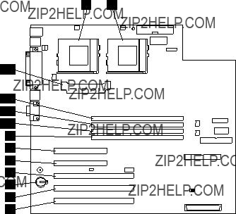
System board connectors
The following illustration shows the location of connectors on the system board.
??1?? Microprocessor 2 (U11)
??2?? Microprocessor 1 (U12)
??3?? PCI 5
??4?? PCI 4
??5?? Battery
??6?? PCI 3
??7?? PCI 2
??8?? PCI 1
??9?? DIMM 1
??10?? DIMM 2
??11?? DIMM 3
??12?? DIMM 4
??13?? Voltage regulator module (VRM)
System board cable connectors
The following illustration shows the location of the cable con- nectors on the system board.
40 Netfinity 3500-M20 ??? Type 8657 Models 21Y, 22Y, 31Y, 32Y,
System board external port connectors
The following illustration identifies system-board connectors for external devices.
System board switches and jumpers
The following illustration shows the switches and jumpers on the system board.
42 Netfinity 3500-M20 ??? Type 8657 Models 21Y, 22Y, 31Y, 32Y,

??1?? Switch block
??2?? Flash ROM page swap jumper (J38)
System board jumper blocks
Any jumper blocks on the system board that are not shown in the illustration are reserved. For normal operation of the system, no jumpers should be installed on any of the jumper blocks except the J38 Flash ROM page swap jumper. See ???Recovering BIOS??? on page 13 for information about the Flash ROM page-swap jumper.
System board switch block
The switch block contains microswitches 1-8. As pictured in this illustration, switch 8 is at the right of the switch block and switch 1 is at the left.
The following table describes the function for each switch.
Table 6. Switches 1-8
Before you begin
Before you begin to install options in the server, become familiar with the safety and handling guidelines provided in:
??????Safety information??? on page 155;
??????Handling electrostatic discharge-sensitive devices??? on page 158; and
??????Safety notices (multi-lingual translations)??? on page 159.
These guidelines will help you work safely while working with the server or options.
???The blue color on components and labels identifies touch points where you can grip a component, move a latch, and so on.

???Make sure that you have an adequate number of prop- erly grounded electrical outlets for the server, monitor, and any other options that you intend to install.
???Back up all important data before you make changes to disk drives.
???For a list of supported options for the Netfinity 3500- M20, refer to http://www.ibm.com/pc/us/compat on the World Wide Web.
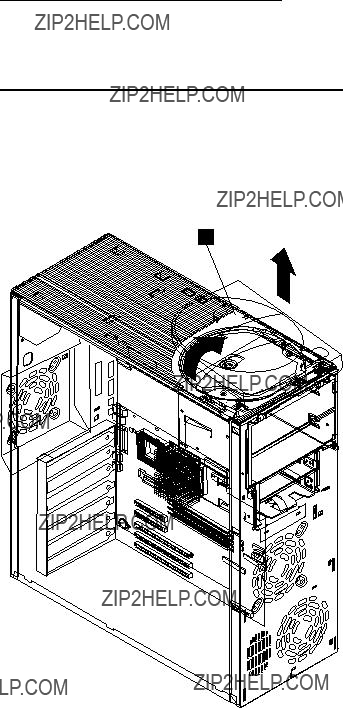
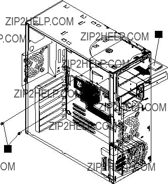
Removing the side cover
Review the information in ???Before you begin??? on page 43.
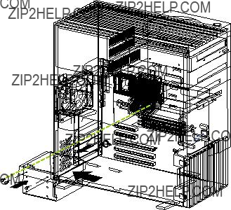
The following illustration shows how to remove the side cover from the server.
Note: The illustrations in this document might differ slightly from your hardware.
??1?? Cover release tab
To remove the left-side cover of the server:
1.Turn off the server and all attached devices and discon- nect all external cables and power cords.
2.If necessary, unlock the server cover.
3.Pull out on the cover-release tab at the rear of the server; then, slide the cover toward the front of the server and remove it.
Attention: For proper cooling and airflow, replace the cover before turning on the server. Operating the server for extended periods of time (over 30 minutes)
44 Netfinity 3500-M20 ??? Type 8657 Models 21Y, 22Y, 31Y, 32Y,
with the cover removed might damage server compo- nents.
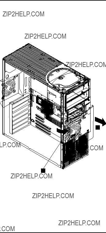
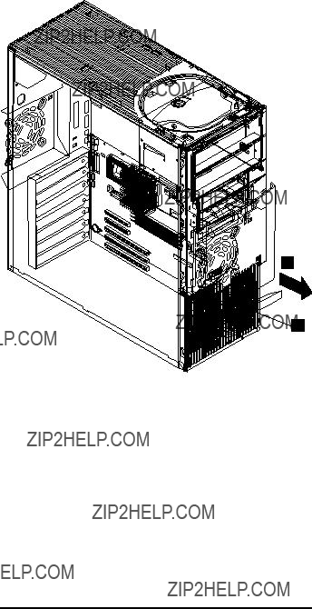
Removing the support bracket
When working with some options such as hard disk drives, microprocessors, and memory modules you must first remove the support bracket to access the location of the option.
3500
Netfinity
M20
??1?? Support bracket
To remove the support bracket:
1.Remove the screw from the bottom front corner.
2.Pull the front corner of the bracket away from the server, then lift the bracket out of the server.
3.Store the screw and bracket in a safe place.
Working with adapters
You can install up to five peripheral component interconnect (PCI) adapters in the expansion connectors, called slots, on the system board of the server.
The server comes with an integrated video controller, which is a component on the system board. When you install a video adapter, the server BIOS automatically disables the integrated video controller.

Note: The illustrations in this document might differ slightly from your hardware.
The following illustration shows the location of the 33 MHz PCI expansion slots on the system board.
??1?? PCI slot 1 32-bit 33 MHz (J29)
??2?? PCI slot 2 32-bit 33 MHz (J31)
??3?? PCI slot 3 64-bit 33 MHz (J35)
??4?? PCI slot 4 64-bit 33 MHz (J39)
??5?? PCI slot 5 64-bit 33 MHz (J40)
Adapter considerations
Before you install adapters, review the following:
???Locate the documentation that comes with the adapter and follow those instructions in addition to the instruc- tions given in this chapter. If you need to change the switch or jumper settings on your adapter, follow the instructions that come with the adapter.
???You can install full-length adapters in all expansion slots.
???You can install a 32-bit adapter in any of the PCI slots, but you might want to install it in a 32-bit slot and use the 64-bit slots for 64-bit adapters.
???Your server supports 5.0V and universal PCI adapters; it does not support 3.3V adapters.
???Your server uses a rotational interrupt technique to con- figure PCI adapters. Because of this technique, you can install a variety of PCI adapters that currently do not support sharing of PCI interrupts.
???PCI slots 1 and 2 are on PCI bus A and PCI slots 3, 4, and 5 are on PCI bus B.
46 Netfinity 3500-M20 ??? Type 8657 Models 21Y, 22Y, 31Y, 32Y,
Note: PCI bus A is sometimes referred to as bus 0; PCI bus B is sometimes referred to as bus 1.
The system scans PCI slots 1 through 5 to assign sys- tem resources; then the system starts (boots) the PCI devices in the following order, if you have not changed the default boot precedence: PCI slots 1 and 2, system board SCSI devices, and then PCI slots 3 through 5.
Note: To change the boot precedence for PCI devices, start the Configuration/Setup Utility program, select Start Options from the main menu, then select the PCI SCSI adapter boot precedence. See ???Configuring the server??? on page 33 for details on using the Configuration/Setup Utility program.
Before you begin:
???Review the information in ???Before you begin??? on page 43 and .
???Read the documentation that comes with your adapter for any special requirements or restrictions.
???Read the documentation that comes with your operat- ing system.
Installing an adapter
The following illustration shows how to install an adapter.
Note: The illustrations in this document might differ slightly from your hardware.
3500
Netfinity
M20
??1?? Access clip
??2?? Expansion slot cover
??3?? Adapter
??4?? Card guide
To install an adapter:
Attention: When you handle Electrostatic Discharge-Sensi- tive devices (ESD), take precautions to avoid damage from static electricity. For details on handling these devices, refer to the following Web site and search for ESD: http://www.ibm.com
1.Review ???Safety information??? on page 155.
2.Turn off the server and peripheral devices and discon- nect all external cables and power cords; then, remove the side cover. See ???Removing the side cover??? on page 44 for details.
3.Determine which expansion slot you will use for the adapter.
Note: Check the instructions that come with the adapter for any requirements or restrictions.
4.Remove the access clip from the rear frame of the server by sliding it upward and then to the right.
5.Remove the expansion-slot cover. Store it in a safe place for future use.
Attention: Expansion-slot covers must be installed on all vacant slots. This maintains the electromagnetic emissions characteristics of the system and ensures proper cooling of system components.
6.Refer to the documentation that comes with your adapter for any cabling instructions. It might be easier for you to route any cables before you install the adapter.
7.Remove the adapter from the static-protective pack- age.
Attention: Avoid touching the components and gold- edge connectors on the adapter.
8.Place the adapter, component-side up, on a flat, static- protective surface.
9.Set any jumpers or switches as described by the adapter manufacturer.
10.Install the adapter:
a.If necessary, push the card guide toward the front of the server until it latches into a position where you can insert the adapter into the guides.
b.Carefully grasp the adapter by its top edge or upper corners, and align it with the expansion slot on the system board.
c.Press the adapter firmly into the expansion slot.
Attention: When you install an adapter in the server, be sure that it is completely and correctly seated in the system-board connector before you apply power. Incomplete insertion might cause damage to the system board or the adapter.
d.When the adapter is fully seated, release the card guide by pushing inward on the latch. Make sure the card guide holds the adapter securely in place.
e.Install the screw that secures the adapter in the expansion slot.
f.Replace the access clip by sliding it onto the rear frame until it latches into place.
48 Netfinity 3500-M20 ??? Type 8657 Models 21Y, 22Y, 31Y, 32Y,
11.Connect any needed cables to the adapter.
Attention: Route cables so that they do not block the flow of air from the fans.
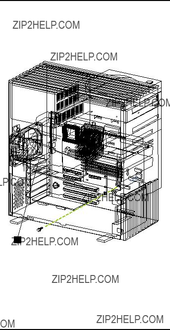
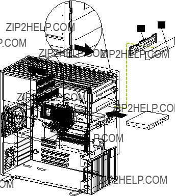
The following illustration shows the rerouting of the SCSI cable. If you install a ServeRAID adapter and intend to use it with internal drives, remove the cable from SCSI connector on the system board and connect it to the RAID adapter.
3500
Netfinity
M20
??1?? SCSI connector
12.If you have other options to install or remove, do so now; otherwise, go to ???Installing the side cover??? on page 60.
Installing internal drives
If you add different types of drives, the system can read mul- tiple types of media and store more data. Several types of drives are available, such as:
???Diskette (installed)
???Hard disk (installed on some models)
???CD-ROM (installed)
???Tape
Internal drive bays
Internal drives are installed in bays. The bays of the Netfin- ity 3500-M20 are in the front of the server, as shown in the following illustration.
3500
Netfinity
M20
??1?? Bay A
??2?? Bay B
??3?? Bay C
??4?? Bay D
??5?? Bay E
??6?? Bay F
??7?? Bay G
To remove or install a drive, you must turn off the server first. Diskette drives, tape drives, and CD-ROM drives are remov- able media drives. You can install removable media drives in bays A, B, C, and D. You can install hard disk drives in bays B, C, E, F, and G.
???The server comes with a 3.5-inch, 1.44 MB diskette drive in bay D, an IDE CD-ROM drive in bay A, and a hard disk drive installed in bay G (in some models).
???The Netfinity 3500 M20 server supports only one dis- kette drive.
???The diskette drive uses 1 MB and 2 MB diskettes. For optimum use, format 1 MB diskettes to 720 KB and for- mat 2 MB diskettes to 1.44 MB.
???Bay B comes without a device installed. This bay is for either a 5.25-inch, half-high, removable-media drive, such as a tape backup drive, or a 3.5-inch SCSI slim high hard disk drive. If you install a 3.5-inch hard disk drive in this bay, you must use the 3.5-inch conversion kit for a 5.25-inch bay supplied with the option.
50 Netfinity 3500-M20 ??? Type 8657 Models 21Y, 22Y, 31Y, 32Y,
???Bay C is for a 3.5-inch slim-high removable-media drive or a SCSI hard disk drive.
Note: The electromagnetic interference (EMI) integrity and cooling of the server are both protected by having bays A through D covered or occupied. When you install a drive, save the filler panel from the bay, in case you later remove the drive and do not replace it with another.
Preinstallation steps (all bays)
Before you install drives in the server, verify that you have all the cables and any other equipment specified in the docu- mentation that comes with the drive. You might also need to perform certain preinstallation activities. Some of the steps are required only during the initial installation of an option.
1.Read ???Safety information??? on page 155, ???Handling elec- trostatic discharge-sensitive devices??? on page 158, and the documentation that comes with the drive.
2.Choose the bay in which you want to install the drive.
3.Check the instructions that come with the drive to see if you need to set any switches or jumpers on the drive. Be sure to set the SCSI ID on a SCSI device.
Installing a drive in bays A, B, C, or D
Note: The EMI integrity and cooling of the server are both protected by having the bays covered or occupied. When you install a drive, save the filler panel from the bay, in case you later remove the drive and do not replace it with another.
3500
Netfinity

??1?? EMI shield
??2?? Filler panel
To install a drive in bay A, B, C, or D:
1.Read the information in ???Preinstallation steps (all bays)??? on page 51.
2.Turn off the server and peripheral devices.
3.Unplug the server.
4.Remove the side cover (see ???Removing the side cover??? on page 44 for details).
5.Use a screwdriver to pry the filler panel away from the server.
6.Remove the EMC shield from the bay.
7.If the drive is a laser product, observe the following safety precaution:
CAUTION:
When laser products (such as CD-ROMs, DVD drives, fiber optic devices, or transmitters) are installed, note the following:
???Do not remove the covers. Removing the cov- ers of the laser product could result in expo- sure to hazardous laser radiation. There are no serviceable parts inside the device.
???Use of controls or adjustments or perfor- mance of procedures other than those speci- fied herein might result in hazardous radiation exposure.
DANGER
Some laser products contain an embedded Class 3A or Class 3B laser diode. Note the following: Laser radia- tion when open. Do not stare into the beam, do not view directly with optical instruments, and avoid direct exposure to the beam.
8.Touch the static-protective bag containing the drive to any unpainted metal surface on the server; then, remove the drive from the bag and place it on a static- protective surface.
9.Set any jumpers or switches on the drive according to the documentation that comes with the drive.
10.Push the drive into the bay and, if it is a CD-ROM drive or floppy disk drive, secure it with two screws (see ???Floppy disk drive??? on page 123 and/or ???CD-ROM drive??? on page 124).
52 Netfinity 3500-M20 ??? Type 8657 Models 21Y, 22Y, 31Y, 32Y,
11.If the drive is an IDE device, plug one connector of the IDE cable into the back of the drive and the other end of the cable into the IDE connector on the system board.
If the drive is a SCSI device, plug one connector of the SCSI cable into the back of the drive and make sure the other end of the cable is connected to the SCSI connector on the system board.
Note: Make sure to route the SCSI cable so that it does not block the air flow to the rear of the drives or over the microprocessors.
12.Connect a power cable to the back of the drive. The connectors are keyed and can be inserted only one way.
13.If you are installing another drive, do so now. Other- wise, continue with the next step.
14.If you have other options to install or remove, do so now; otherwise, replace the cover (see ???Installing the side cover??? on page 60 for details).
Installing a hard disk drive in bays E, F, or G
3500
Netfinity
To install a hard disk drive in bays E, F, or G:
1.Read the information in ???Preinstallation steps (all bays)??? on page 51.
2.Turn off the server and peripheral devices.
3.Unplug the server.
4.Remove the cover (see ???Removing the side cover??? on page 44 for details).
5.Remove the support bracket.
6.Remove the drive cage.
a.Remove the screw from the top rear corner of the drive cage. Store the screw in a safe place.

b.If the server has a hard disk drive installed in the drive cage, disconnect the cables from the rear of the drive.
c.Carefully pull the drive cage out of the server.
7.Remove the plastic bag containing the drive screws from the outside rear of the server. Slide each drive into the drive cage and secure it with four of the screws provided in the plastic bag.
8.Reinstall the cage in the server and secure it with the screw you removed previously.
9.Connect the server SCSI and power cables to the rear of the drives.
Note: Make sure to route the SCSI cable so that it does not block the air flow to the rear of the drives or over the microprocessors.
10.If you have other options to install or remove, do so now; otherwise, replace the support bracket and the side cover (see ???Installing the side cover??? on page 60 for details).
Installing memory-module kits
Adding memory to the server is an easy way to make pro- grams run faster. You can increase the amount of memory in the server by installing options called memory-module kits. Each kit contains one industry-standard, dual-inline memory module (DIMM). The server uses a noninterleaved memory configuration.
The server comes with a dual inline memory module (DIMM) installed on the system board in DIMM slot 4.
Notes:
1.When installing additional memory modules, install the second memory module in the connector labeled DIMM3, the third in DIMM2, and the fourth in DIMM1. (See the following illustration for memory connector locations.)
2.The Netfinity 3500 M20 server supports 128MB, 256MB, and 512MB DIMMs. These DIMMs can be installed in any memory slot. The server supports a minimum of 128MB and a maximum of 2GB of system memory. See the ServerProven list at http://www.ibm.com/pc/compat for a list of memory modules for use with the server.
3.Installing or removing DIMMs changes the configura- tion information in the server. Therefore, after installing or removing a DIMM, you must save the new configura- tion information by using the Configuration/Setup Utility program. When you restart the server, the system dis- plays a message indicating that the memory configura- tion has changed. Start the Configuration/Setup Utility program and select Save Settings. See ???Configuring the server??? on page 33 for more information.
4.The illustrations in this document might differ slightly from your hardware.
54 Netfinity 3500-M20 ??? Type 8657 Models 21Y, 22Y, 31Y, 32Y,

??1?? DIMM connector 4
??2?? DIMM connector 3
??3?? DIMM connector 2
??4?? DIMM connector 1
??5?? DIMM 2
??6?? DIMM 1
Before you begin:
???Review ???Before you begin??? on page 43.
???Read the documentation that comes with the option.
To install a DIMM:
Attention: When you handle Electrostatic Discharge-Sensi- tive devices (ESD), take precautions to avoid damage from static electricity. For details on handling these devices, refer to the following Web site and search for ESD: http://www.ibm.com
Note: When installing memory in DIMM slot 4, you may need to remove the hard disk drive cage (see ???Install- ing a hard disk drive in bays E, F, or G??? on page 53).
1.Turn off the server and disconnect all power cords and external cables; then, remove the side cover (see ???Removing the side cover??? on page 44).
2.Touch the static-protective package containing the DIMM to any unpainted metal surface on the server. Then, remove the DIMM from the package.
Note: To avoid breaking the retaining clips or damag- ing the DIMM connectors, handle the clips gen- tly.
3.Install the DIMM:
a.Turn the DIMM so that the pins align correctly with the connector.

b.Insert the DIMM into the connector by pressing on one edge of the DIMM and then on the other edge of the DIMM. Be sure to press straight into the connector. Be sure that the retaining clips snap into the closed positions.
c.Make sure the retaining clips are in the closed position. If a gap exists between the DIMM and the retaining clips, the DIMM has not been prop- erly installed. In this case, open the retaining clips and remove the DIMM; then, reinsert the DIMM.
4.If you have other options to install or remove, do so now; otherwise, go to ???Installing the side cover??? on page 60.
Installing a microprocessor kit
The server comes with one microprocessor installed on the system board. If you install an additional microprocessor kit, the server can operate as a symmetric multiprocessing (SMP) server. With SMP, certain operating systems and application programs can distribute the processing load between the microprocessors. This enhances performance for database and point-of-sale applications, integrated man- ufacturing solutions, and other applications.
Notes:
1.Before you install a new microprocessor, review the documentation that comes with the microprocessor, so that you can determine whether you need to update the server basic input/output system (BIOS). The latest level of BIOS for the server is available through the World Wide Web.
2.Obtain an SMP-capable operating system (optional). For a list of supported operating systems, see http://www.ibm.com/pc/us/compat/ on the World Wide Web.
3.The server comes with one microprocessor installed in microprocessor connector U12. This is the startup (boot) microprocessor. If you install a microprocessor in microprocessor connector U11, that one becomes the startup processor and the microprocessor installed in connector U12 is the application processor.
4.The illustrations in this document might differ slightly from the server.
56 Netfinity 3500-M20 ??? Type 8657 Models 21Y, 22Y, 31Y, 32Y,

??1?? Microprocessor 2 connector
??2?? Microprocessor 1
??3?? VRM
??4?? Microprocessor orientation indicator
??5?? Heatsink retainer
??6?? Heatsink
??7?? Microprocessor 2
??8?? Terminator card
To install an additional microprocessor:
Note: Review the information in ???Before you begin??? on page 43.
Attention: When you handle Electrostatic Discharge-Sen- sitive devices (ESD), take precautions to avoid damage from static electricity. For details on handling these devices, refer to the following Web site and use a search term of ESD: http://www.ibm.com/.
1.Review ???Safety information??? on page 155.
2.Turn off the server and peripheral devices and discon- nect all external cables and power cords; then remove the cover (see ???Removing the side cover??? on page 44 for details).
3.Remove the support bracket and the air baffle from behind the support bracket. Store them both in a safe place.
4.Lift up the release lever and remove the terminator card from the microprocessor connector.
5.Install the microprocessor:
a.Touch the static-protective package containing the new microprocessor to any unpainted metal sur-
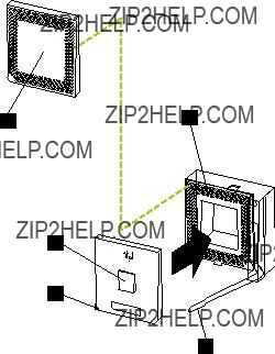
face on the server; then, remove the microproces- sor from the package.
b.Orient the microprocessor over the microproces- sor connector as shown in the following illustra- tion. Carefully press the microprocessor into the connector.
??1?? Microprocessor 2 connector
??2?? Lever
??3?? Microprocessor orientation indicator
??4?? Microprocessor 2
??5?? Terminator card
Note: Do not use excessive force when pressing the microprocessor into the connector.
6.Push the release lever down to lock the microprocessor into place.
7.Install the heat sink on the microprocessor:
a.Peel the plastic protective strip off the bottom of the heat sink. Make sure the square of thermal material is still on the bottom of the heat sink.
b.Align and place the heat sink on top of the micro- processor.
c.Align and place the clip over the heat sink, then snap it into place.
8.Place the terminator card in the static-protective pack- age that the new microprocessor was shipped in, and store it in a safe place. You will need to install the ter- minator card again if you ever remove the microproces- sor and do not replace it with another microprocessor.
58 Netfinity 3500-M20 ??? Type 8657 Models 21Y, 22Y, 31Y, 32Y,
9.Install the voltage regulator module (VRM) included in the microprocessor kit.
Attention: Use of other VRMs might cause the server to overheat.
a.Center the VRM over the VRM connector. Make sure that the VRM is oriented and aligned cor- rectly.
b.Press the VRM into the connector.
Notes:
a.If you remove the microprocessor later, remember to install the terminator card in the appropriate microprocessor connector and to remove the VRM.
b.To remove the VRM, press down on the two release latches on the system board at the bottom of the VRM and gently lift the VRM away from the board.
10.If you have other options to install or remove, do so now; otherwise, replace the support bracket and the air baffle, then go to ???Installing the side cover??? on page 60.
Attention: To avoid damage and ensure proper server operation when you install a new or an additional micropro- cessor, use microprocessors that have the same cache size and type, and the same clock speed. Microprocessor inter- nal and external clock frequencies must be identical.
To remove a microprocessor:
Note: Do not use any tools when removing the micropro- cessor.
Attention: When you handle Electrostatic Discharge-Sen- sitive devices (ESD), take precautions to avoid damage from static electricity. For details on handling these devices, refer to the following Web site and use a search term of ESD: http://www.ibm.com/
1.Review the safety precautions listed in ???Safety informa- tion??? on page 155.
2.Turn off the server and peripheral devices and discon- nect all external cables and power cords; then remove the cover (see ???Removing the side cover??? on page 44 for details).
3.Remove the support bracket and the air baffle from behind the support bracket. Store them both in a safe place.
4.Remove any heatsinks:
Note: A thermal material is used between the heatsink and the processor. This material when heated and cooled causes the heatsink to adhere to the processor. Some force may be required to remove the heatsink.
a.Press the handle of the heatsink clip down and toward the back until it releases, and lift it up and off the heatsink.
b.Firmly grasp heat sink and pull upward.
Attention: Do not use excessive force or tools to remove the heatsink.

c.Discard the used heatsink.
5.Lift up the release lever and remove the microproces- sor from the connector. Store the microprocessor in a static-protective bag for possible future use.
6.If you are installing a new microprocessor, go to Install- ing an additional microprocessor on page 57.
If you are not replacing the microprocessor, then you must reinstall the terminator card. Push the release lever down to lock the terminator card into place.
Completing the installation
To complete the installation, you must reconnect all cables that you disconnected, reinstall all bezels, reinstall the side cover, and, for certain options, run the Configuration/Setup Utility program. Follow the instructions in this section.
Note: If you have just plugged the power cords of the server into an electrical outlet, you will have to wait approxi- mately 20 seconds before pressing the power-control button.
Installing the side cover
The following illustration shows how install the side cover.
Note: The illustrations in this document might differ slightly from your hardware.
??1?? Cover release tab
To install the left-side cover:
60 Netfinity 3500-M20 ??? Type 8657 Models 21Y, 22Y, 31Y, 32Y,
1.Clear any cables that might impede the replacement of the cover.
2.Install the side cover by placing it into position and slid- ing it to the rear position as shown. Make sure the cover is latched into position.
3.Lock the cover.
4.Make sure the stabilizing feet are rotated outward so that they properly support the server.
5.Reconnect the external cables and cords to the server, then plug the power cords into electrical outlets.
Connecting external options
You can attach a SCSI storage expansion enclosure to the server.
Before you begin:
???Review ???Before you begin??? on page 43.
???Read the documentation that comes with the option.
To attach an external device:
1.Be sure the server and all attached devices are turned off.
2.Follow the instructions that come with the option to pre- pare it for installation and to connect it to the server.
Note: If you are attaching a SCSI device, see ???SCSI port??? on page 66 for information about SCSI cabling and SCSI IDs.
I/O connector locations
The following illustration shows the input/output connectors (ports) and the expansion slots on the rear of the server. For pin assignments and other details about these connectors, see ???Input/output ports??? on page 62.
??1?? Power cord connector
??2?? Mouse
??3?? Keyboard
??4?? USB 1
??5?? USB 2
??6?? Serial A
??7?? Parallel
??8?? Serial B
??9?? Ethernet
??10?? Video
Input/output ports
This section provides information about the input/output (I/O) ports on the server. These ports include the following:
???One parallel port
???One video port
62 Netfinity 3500-M20 ??? Type 8657 Models 21Y, 22Y, 31Y, 32Y,

???One keyboard port
???One auxiliary pointing device (mouse) port
???Two serial ports
???Two Universal Serial bus (USB) ports
???One Ethernet port
Parallel port
The server has one parallel port. This port supports three standard Institute of Electrical and Electronics Engineers (IEEE) 1284 modes of operation: Standard Parallel Port (SPP), Enhanced Parallel Port (EPP), and Extended Capa- bility Port (ECP).
Viewing or changing the parallel-port assignments
You can use the built-in Configuration/Setup Utility program to configure the parallel port as bidirectional; that is, so that data can be both read from and written to a device. In bidi- rectional mode, the server supports the ECP and EPP modes.
To view or change the parallel-port assignment:
1.Restart the server and watch the monitor screen.
2.When the message Press F1 for Configura- tion/Setup appears, press F1.
3.From the main menu, select Devices and I/O Ports; then, press Enter.
4.Select the parallel port; then, use the arrow keys to advance through the settings available.
Note: When you configure the parallel port as bidirec- tional, use an IEEE 1284-compliant cable. The maximum length of the cable must not exceed 3 meters (9.8 feet).
5.Select Save Settings; then, select Exit Setup to exit from the Configuration/Setup Utility main menu.
Parallel port connector
The following table shows the pin-number assignments for the 25-pin, female D-shell parallel-port connector on the rear of the server.
Table 7. Parallel-port connector pin-number assignments
Table 7. Parallel-port connector pin-number assignments
Video port
The server comes with an integrated super video graphics array (SVGA) video controller. This controller is not remov- able, but you can disable it by installing a PCI video adapter.
Note: If you install a PCI video adapter, the server BIOS will automatically disable the integrated video controller.
The following table shows the pin-number assignments for the 15-pin analog video connector on the rear of the server.
5 1
15 11
Table 8. Video-port connector pin-number assignments
64 Netfinity 3500-M20 ??? Type 8657 Models 21Y, 22Y, 31Y, 32Y,
Table 8. Video-port connector pin-number assignments
13Horizontal synchronization (Hsynch)
14Vertical synchronization (Vsynch)
15DDC SCL
Keyboard port
There is one keyboard port on the rear of the server.
Note: If you attach a standard (non-USB) keyboard to the keyboard connector, the USB ports and devices will be disabled during the power-on self-test (POST).
The following table shows the pin-number assignments for the keyboard connector on the rear of the server.
Table 9. Keyboard connector pin-number assignments
Auxiliary-device (pointing device) port
The system board has one auxiliary-device port that sup- ports a mouse or other pointing device.
The following table shows the pin-number assignments for the auxiliary-device connector on the rear of the server.
Table 10. Auxiliary-device connector pin-number assignments
1Data
2Not connected

Table 10. Auxiliary-device connector pin-number assignments
3Ground
4+5 V dc
5Clock
6Not connected
SCSI port
The server has an integrated dual-channel small computer system interface (SCSI) controller. This controller supports an Ultra160 SCSI internal channel. This channel supports up to 15 SCSI devices. In addition, this controller uses:
???Double-transition clocking to achieve high transfer rates
???Domain name validation to negotiate compatible data transfer speeds with each device
???Cyclic-redundancy checking (CRC), instead of the usual parity checking, to significantly improve data reli- ability
???An active terminator on the system board for SCSI bus termination
If you install a SCSI adapter in the server, you can use its SCSI connector to connect different types of small computer system interface (SCSI) devices.
Note: If you install a PCI RAID adapter, you can move the SCSI cable from the system-board SCSI connector to an internal channel connector on the RAID adapter if you want to control the internal drives from the adapter.
SCSI cabling requirements
You can install five internal SCSI devices using the SCSI cable that comes with the server. If you plan to attach exter- nal SCSI devices, you must install an optional SCSI adapter and order additional SCSI cables. To select and order the correct cables for use with external devices, contact your IBM reseller or IBM marketing representative.
For information about the maximum length of SCSI cable between the terminated ends of the cable, refer to the ANSI SCSI standards. Adhering to these standards will help ensure that the server operates properly.
Setting SCSI IDs
Each SCSI device connected to a SCSI controller must have a unique SCSI ID. This ID enables the SCSI controller to identify the device and ensure that different devices on the same SCSI channel do not attempt to transfer data simulta- neously. SCSI devices that are connected to different SCSI channels can have duplicate SCSI IDs.
To install external SCSI devices, you must first install an optional SCSI PCI adapter. Refer to the information that is provided with the device for instructions to set its SCSI ID.
66 Netfinity 3500-M20 ??? Type 8657 Models 21Y, 22Y, 31Y, 32Y,
SCSI connector pin-number assignments
The following table shows the pin-number assignments for the 68-pin SCSI connectors.
Table 11. 68-pin SCSI connector pin-number assignments
Serial ports
The server has two standard serial ports: Serial port A and Serial port B.

Some application programs require specific ports, and some modems function properly only at certain communication port addresses. You might need to use the Configura- tion/Setup Utility program to change communication port address assignments to prevent or resolve address con- flicts.
Viewing or changing the serial-port assignments
To view or change the serial-port assignments:
1.Restart the server and watch the monitor screen.
2.When the message Press F1 for Configura- tion/Setup appears, press F1.
3.From the main menu, select Devices and I/O Ports; then, press Enter.
4.Select the serial port; then, use the arrow keys to advance through the settings available.
5.Select Save Settings; then, select Exit Setup to exit from the Configuration/Setup Utility main menu.
Serial-port connectors
The following table shows the pin-number assignments for the 9-pin, male D-shell serial-port connectors on the rear of the server. These pin-number assignments conform to the industry standard.
15
6 9
Table 12. Serial-port connectors pin-number assignments
Universal Serial Bus ports
The server has two Universal Serial Bus (USB) ports, which configure automatically. USB is an emerging serial interface standard for telephony and multimedia devices. It uses Plug and Play technology to determine the type of device attached to the connector.
Notes:
1.If you attach a standard (non-USB) keyboard to the keyboard connector, the USB ports and devices will be disabled during the power-on self-test (POST).
2.If you install a USB keyboard that has a mouse port, the USB keyboard emulates a mouse and you will not be able to disable the mouse settings in the Configura- tion/Setup Utility program.
68 Netfinity 3500-M20 ??? Type 8657 Models 21Y, 22Y, 31Y, 32Y,

USB cables and hubs
You need a 4-pin cable to connect devices to USB 1 or USB 2. If you plan to attach more than two USB devices, you must use a hub to connect the devices. The hub provides multiple connectors for attaching additional external USB devices.
USB technology provides up to 12 megabits-per-second (Mbps) speed with a maximum of 127 external devices and a maximum signal distance of five meters (16 ft.) per seg- ment.
USB-port connectors
Each USB port has an external connector on the rear of the server for attaching USB compatible devices.
The following table shows the pin-number assignments for the USB-port connectors on the rear of the server.
Table 13. USB-port connector pin-number assignments
1VCC
2-Data
3+Data
4Ground
Ethernet port
The server comes with an integrated Ethernet controller. This controller provides an interface for connecting to 10- Mbps or 100-Mbps networks and provides full-duplex (FDX) capability, which enables simultaneous transmission and reception of data on the Ethernet local area network (LAN).
To access the Ethernet port, connect a Category 3, 4 or 5 unshielded twisted-pair (UTP) cable to the RJ-45 connector on the rear of the server.
Note: The 100BASE-TX Fast Ethernet standard requires that the cabling in the network be Category 5 or higher.
Configuring the Ethernet controller
When you connect the server to the network, the Ethernet controller automatically detects the data-transfer rate (10Mbps or 100Mbps) on the network and then sets the controller to operate at the appropriate rate. That is, the Ethernet controller will adjust to the network data rate, whether the data rate is standard Ethernet (10BASE-T), Fast Ethernet (100BASE-TX), half duplex (HDX), or full duplex (FDX). The controller supports half-duplex (HDX) and full- duplex (FDX) modes at both speeds.
The Ethernet controller is a PCI Plug and Play device. You do not need to set any jumpers or configure the controller for the operating system before you use the Ethernet controller. However, you must install a device driver to enable the oper- ating system to address the Ethernet controller. The device drivers are provided on the ServerGuide CDs.
Failover for redundant Ethernet
The IBM Netfinity 10/100 Ethernet Adapter or the IBM 10/100 Ethernet PCI family of adapters are optional redun- dant network interface cards (NIC adapter) that you can install in the server. If you install this NIC adapter and con- nect it to the same logical segment as the primary Ethernet controller, you can configure the server to support a failover function. You can configure either the integrated Ethernet controller or the NIC adapter as the primary Ethernet con- troller. In failover mode, if the primary Ethernet controller detects a link failure, all Ethernet traffic associated with it is switched to the redundant (secondary) controller. This switching occurs without any user intervention. When the primary link is restored to an operational state, the Ethernet traffic switches back to the primary Ethernet controller.
High Performance Ethernet Modes
The Ethernet controller supports optional modes, such as teaming, priority packets, and virtual LANs, which provide higher performance and throughput for the server.
Teaming Mode: The Ethernet controller provides options, called teaming options. These options increase throughput and fault tolerance when running with Windows NT 4.0 or NetWare 4.1x or later.
???Adapter fault tolerance (AFT) provides automatic redundancy for the adapter. If the primary adapter fails, the secondary adapter takes over. Adapter fault toler- ance supports from 2 to 4 adapters per team.
???Adaptive load balancing (ALB) allows you to balance the transmission data flow among 2 to 4 adapters. ALB also includes the AFT option. You can use ALB with any 100BASE-TX switch.
???Cisco Fast EtherChannel (FEC) creates a team of 2 to 4 adapters to increase transmission and reception throughput. FEC also includes the AFT option. You can only use FEC with a switch that has FEC capability.
Teaming requires you to install at least one additional Ether- net adapter. For additional information about the teaming modes, refer to the documentation that comes with these additional adapters.
Priority Packet Mode: Priority Packet is a traffic-prioriti- zation utility that enables you to set up filters to process high-priority traffic before normal traffic. You can send infor- mation from critical nodes or applications with an indicated priority. Because you set this priority at the host or entry point of the network, the network devices can base forward- ing decisions on priority information defined in the packet.
Priority Packet information is available on the IBM Network- ing Web site at: http://www.ibm.com/networking/support.
Priority Packet prioritizes traffic based on priority filters. These are parameters you assign to outgoing (transmit) packets. Using the Priority Filter Wizard, you can set up pre- defined or custom priority filters based on a node (MAC) address, Ethernet type, or by various properties of the proto- col and port. Priority Packet provides two different methods
70 Netfinity 3500-M20 ??? Type 8657 Models 21Y, 22Y, 31Y, 32Y,
for prioritizing traffic: IEEE 802.1p tagging and High Priority Queue.
IEEE 802.1p is a new IEEE standard for tagging, or adding additional bytes of information to packets with different prior- ity levels. Packets are tagged with 4 additional bytes, which increase the packet size and indicate a priority level. When you send these packets out on the network, the higher prior- ity packets are transferred first. Priority packet tagging (also known as Traffic Class Expediting) allows the adapter to work with other elements of the network (such as switches and routers) to deliver priority packets first. You can assign specific priority levels from 0 (low) to 7 (high).
You can assign values to packets based on their priority when you use the IEEE 802.1p standard for packet tagging. This method requires a network infrastructure that supports packet tagging. The routing devices receiving and transfer- ring these packets on the network must support 802.1p for tagging to be effective.
After you set up the priority filter in Priority Packet, you must launch IBMSet and select 802.1p/802.1Q Tagging on the Advanced tab.
Note: IEEE 802.1p tagging increases the size of the pack- ets it tags. Some hubs and switches will not recog- nize the larger packets and will drop them. Check the hub or switch documentation to see if they support 802.1p. (You can configure the switch to strip the tags from the packets and send it on to the next desti- nation as normal traffic.) If these devices do not sup- port 802.1p or if you are not sure, use High Priority Queue (HPQ) to prioritize network traffic.
The requirements for effectively using IEEE 802.1p tagging are:
???The other devices receiving and routing 802.1p tagged packets must support 802.1p.
???The adapters on these devices must support 802.1p. The Ethernet controller in the Netfinity 3500 M20 and all IBM Netfinity 10/100 Ethernet Security Adapters support 802.1p.
???The adapter cannot be assigned to an adapter team.
???If you are setting up VLANs and packet tagging on the same adapter, 802.1p/802.1Q Tagging must be enabled on the IBMSet Advanced tab.
If the network infrastructure devices do not support IEEE 802.1p or you are not sure, you can still define filters and send packets as high priority. While High Priority Queue (HPQ) does not provide the precise priority levels of 802.1p tagging, it does assign traffic as either high or low priority and sends high priority packets first. Therefore, if there are multiple applications on a system sending packets, the pack- ets from the application with a filter are sent out first. HPQ does not change network routing, nor does it add any infor- mation to the packets.
To assign HPQ, you can specify it using Priority Packet when you create or assign a filter.
To effectively use HPQ tagging, the adapter cannot be assigned to an adapter team.
Virtual LAN Mode: A virtual LAN (VLAN) is a logical grouping of network devices put together as a LAN, regard- less of their physical grouping or collision domains. Using VLANs increases network performance and improves net- work security.
VLANs offer you the ability to group users and devices together into logical workgroups. This can simplify network administration when connecting clients to servers that are geographically dispersed across the building, campus, or enterprise network.
Normally, VLANs are configured at the switch and any com- puter can be a member of one VLAN per installed network adapter. The Ethernet controller supersedes this by commu- nicating directly with the switch, allowing multiple VLANs on a single network adapter (up to 64 VLANs).
To set up VLAN membership, the Ethernet controller must be attached to a switch that has VLAN capability. You also need to use Windows NT 4.0 or later, or Novell NetWare 4.1x or later.
Notes:
1.Windows NT versions prior to 4.0 do not support VLANs.
2.VLANs require NT 4.0 with Service Pack 3.0 and the NDIS driver hotfix from Microsoft.
3.In Windows NT, VLANs cannot be implemented on controllers that have been configured for teaming options. NetWare can support teaming options and VLANs on the same adapters.
To join a VLAN from Windows NT 4.0:
1.Create a VLAN on the switch. Use the parameters you assign there to join the VLAN from the server. Refer to the switch documentation for more information.
2.Double-click the Network icon in the Control Panel win- dow.
3.On the Adapters tab, select the adapter you want to be on the VLAN and select Properties.
4.In IBMSet, select Join VLAN. Note that VLANs cannot be assigned to adapters that are already defined to have an adapter teaming option.
5.Enter the VLAN ID and VLAN name. The VLAN ID must match the VLAN ID of the switch. The ID range is from 1 to 1000. The VLAN name is for information only and does not need to match the name on the switch.
6.Select Join VLAN. Repeat steps 3 through 5 for each VLAN you want the server to join. The VLANs you add are listed on the Adapters tab.
7.Select Close and restart the computer.
72 Netfinity 3500-M20 ??? Type 8657 Models 21Y, 22Y, 31Y, 32Y,
Ethernet port connector
The following table shows the pin-number assignments for the ethernet port connector. These assignments apply to both 10BASE-T and 100BASE-TX devices.
??1?? Ethernet speed 100 Mbps LED
??2?? Ethernet link status LED
Table 14. Ethernet RJ-45 connector pin-number assignments.
74 Netfinity 3500-M20 ??? Type 8657 Models 21Y, 22Y, 31Y, 32Y,

Netfinity Manager
Netfinity Manager provides powerful hardware systems- management capabilities, including access to all systems on the network that are running Netfinity Manager or Client Ser- vices for Netfinity Manager. In addition to all standard Client Services for Netfinity Manager functions, Netfinity Manager also features directory transfers and file, remote screen cap- tures, and remote command-line sessions. Netfinity Man- ager also enables you to export data collected by System Information Tool, System Profile, Software Inventory, and System Monitor to a DB2, Lotus Notes, or SQL or DB2 via an open database connectivity (ODBC) database (ODBC export is available on Windows NT systems only). Finally, Netfinity Manager enables some services to be started at scheduled times and dates for simplified, automated sys- tems management.
Netfinity Manager also provides two powerful features that enable you to access the Netfinity Manager system and all Netfinity Manager systems from a system that is not attached to the managing system network:
???Serial Connection Control
Use the Serial Connection Control service to use a Net- finity Manager system modem to establish a connec- tion with any Netfinity Manager system that has a modem. Once this connection is established, the Net- finity Manager has full access to Netfinity Manager ser- vices, just as though the remote system were part of the managing system network.
???Netfinity Manager for Web
Netfinity Manager for Web enables access and remote control of the Netfinity Manager system over the Inter- net, using any system that has an Internet connection and a World Wide Web (WWW) browser. With the Net- finity Manager for Web, the Netfinity Manager systems can be accessed from anywhere in the world.
Managing your IBM Netfinity server with Netfinity Manager
A Netfinity Manager systems management environment consists of two parts:
???A systems management console running Netfinity Man- ager. The systems management console is the system from which administrative tasks are performed.
???Client systems running Client Services for Netfinity Manager. Client Services for Netfinity Manager runs on all client systems in your network and enables Netfinity Manager to remotely monitor, inventory, manage, and troubleshoot the systems on which it is installed.
Once you have installed Netfinity Manager and Client Ser- vices for Netfinity Manager on the appropriate systems you are ready to use Netfinity Manager to remotely inventory, monitor, and troubleshoot the client systems in your network.
The copy of Netfinity Manager that is included with Server- Guide entitles you to one Netfinity Manager installation. You are also entitled to additional installations of Client Services for Netfinity Manager, which can be installed on other sys- tems in your network. Furthermore, additional Netfinity Man- ager and Client Services for Netfinity Manager licenses are available for purchase from your IBM representative.
If you plan to use your IBM Netfinity 3500-M20 server as a systems management console, install Netfinity Manager on your server and then install Client Services for Netfinity Man- ager on your networked client systems. If you plan to use another system, such as a networked workstation, to man- age and maintain your IBM Netfinity 3500-M20 server, install Netfinity Manager on the networked system and install Client Services for Netfinity Manager on your server. See the fol- lowing table for supported installations for your server:
1.This section provides installation instructions for Netfin- ity Manager only. For Client Services for Netfinity Man-
76 Netfinity 3500-M20 ??? Type 8657 Models 21Y, 22Y, 31Y, 32Y,

ager installation instructions, see the documentation listed in ???Getting more information about Netfinity Man- ager??? on page 106.
2.This section provides installation instructions for all operating systems supported by Netfinity Manager. However, not all operating systems described in this section are certified for use with all Netfinity server models. For a list of supported operating system for you Netfinity server model, see the Server Proven list at
http://www.ibm.com.pc/compat
Netfinity Manager documentation
The Netfinity directory on the ServerGuide Netfinity Applica- tions CD contains online versions (*.PDF format) of all Net- finity Manager documentation. For more information on included documentation, see ???Getting more information about Netfinity Manager??? on page 106.
Netfinity Manager system requirements
The minimum system requirements for Netfinity Manager vary based on which supported operating system is running on your system.
???If you are installing Netfinity Manager for OS/2, see ???Netfinity Manager for OS/2 system requirements???.
???If you are installing Netfinity Manager for Windows 95 (or Windows 98), see ???Netfinity Manager for Windows 95 and Windows 98 system requirements??? on page 78.
???If you are installing Netfinity Manager for Windows NT, see ???Netfinity Manager for Windows NT system requirements??? on page 79.
Netfinity Manager for OS/2 system requirements
The minimum system requirements for Netfinity Manager for OS/2 are:
???OS/2 version 3.0 or later
???Approximately 19 MB???22 MB of hard disk space (space required depends on system configuration)
???A LAN adapter card and one or more of the following communications protocols:
???IBM TCP/IP for OS/2 version 1.2 or later (required for Netfinity Manager with Web Enhancement)
???NetBIOS
Note: The Netfinity Manager NetBIOS require- ments are three names, two sessions, and nine network control blocks (NCBs).
???IPX
???SNA (IBM Communications Manager/2 version
1.1only)
Note: Systems using Netfinity Manager with Microsoft SNA Server cannot communicate with systems that run the Microsoft SNA Server client. Netfinity Manager supports only server-to-server communications between systems that run Microsoft SNA Server software. However, Netfinity Man- ager systems running Microsoft SNA Server can communicate with other Netfin- ity Manager systems using any of the other supported SNA stacks.
??? A 9600 baud or greater modem (optional).
The hard disk requirement for Client Services for Netfinity Manager is 6.5 MB???9 MB of hard disk space. All other sys- tem requirements are the same as for Netfinity Manager for OS/2.
Note: Serial Connection Control will not function on sys- tems that do not have a properly installed and config- ured modem.
Netfinity Manager for Windows 95 and Windows 98 system requirements
The minimum system requirements for Netfinity Manager for Windows 95 are:
???Microsoft Windows 95 or later
???Approximately 17 MB???20 MB of hard disk space (space required depends on system configuration)
???A LAN adapter card and one or more of the following communications protocols:
???TCP/IP (must be WinSock Version 1.1-compati- ble; required for Netfinity Manager with Web Enhancement)
???NetBIOS
Note: The Netfinity Manager NetBIOS require- ments are three names, two sessions, and nine network control blocks (NCBs).
???IPX
???SNA (PCOMM 4.1 or later SNA stack)
Note: Systems using Netfinity Manager with Microsoft SNA Server cannot communicate with systems that run the Microsoft SNA Server client. Netfinity Manager supports only server-to-server communications between systems that run Microsoft SNA Server software. However, Netfinity Man- ager systems running Microsoft SNA Server can communicate with other Netfin- ity Manager systems using any of the other supported SNA stacks.
??? A 9600 baud or greater modem (optional).
The hard disk requirement for Client Services for Netfinity Manager is 6.5 MB???9 MB of hard disk space. All other sys- tem requirements are the same as for Netfinity Manager for Windows NT.
78 Netfinity 3500-M20 ??? Type 8657 Models 21Y, 22Y, 31Y, 32Y,
Note: Serial Connection Control will not function on sys- tems that do not have a properly installed and config- ured modem.
Netfinity Manager for Windows NT system requirements
The minimum system requirements for Netfinity Manager for Windows NT are:
???Microsoft Windows NT version 4.0 or later
???Approximately 17 MB???20 MB of hard disk space (space required depends on system configuration)
???A LAN adapter card and one or more of the following communications protocols:
???TCP/IP (must be WinSock Version 1.1-compati- ble; required for Netfinity Manager with Web Enhancement)
???NetBIOS
Note: The Netfinity Manager NetBIOS require- ments are three names, two sessions, and nine network control blocks (NCBs).
???IPX
???SNA (Microsoft SNA Server version 2.11 with Ser- vice Pack 1 and WCPIC32.DLL dated 01/22/97 or later. This DLL is available from Microsoft)
Note: Systems using Netfinity Manager with Microsoft SNA Server cannot communicate with systems that run the Microsoft SNA Server client. Netfin- ity Manager supports only server-to-server com- munications between systems that run Microsoft SNA Server software. However, Netfinity Man- ager systems running Microsoft SNA Server can communicate with other Netfinity Manager sys- tems using any of the other supported SNA stacks.
??? A 9600 baud or greater modem (optional).
The hard disk requirement for Client Services for Netfinity Manager is 6.5 MB???9 MB of hard disk space. All other sys- tem requirements are the same as for Netfinity Manager for Windows NT.
Notes:
1.Serial Connection Control will not function on systems that do not have a properly installed and configured modem.
2.To most effectively manage Windows NT systems, any user that will be using Netfinity Manager on a Windows NT system (locally or remotely) must have administra- tor-level access to the system.

Starting the Netfinity Manager installation program
For instructions on installing Client Services for Netfinity Manager, see the documentation listed in ???Getting more information about Netfinity Manager??? on page 106.
To start the Netfinity Manager installation program on a sys- tem that is running Windows NT 4.0:
1.Start the computer with your operating system.
2.Place the ServerGuide Netfinity Applications CD into the CD-ROM drive.
3.Follow the instructions for your operating system below:
???OS/2 Warp Server
a.From a command prompt, type x:
where x is the CD-ROM drive letter, and then press Enter.
b.Type
SCOS2
and then press Enter. The ServerGuide Net- finity Applications windows opens.
c.Select IBM Netfinity Manager from the Available Applications selection list.
Note: To install Client Services for Netfinity Manager, select Client Services for Netfinity Manager from the Available Applications list and then refer to the
Client Services for Netfinity Manager User???s Guide for additional installation instructions.
d.Click Install Product to start the installation process.
???Windows 95, 98, or NT
a.Click the Start button.
b.Click Run... from the Start button menu.
c.Type x:\SCW95
where x is the drive letter of the CD-ROM drive in the Command Line field and then click OK. The ServerGuide Netfinity Applica- tions windows opens.
d.Select IBM Netfinity Manager from the Available Applications selection list.
Note: To install Client Services for Netfinity Manager, select Client Services for Netfinity Manager from the Available Applications list and then refer to the
Client Services for Netfinity Manager User???s Guide for additional installation instructions.
e.Click Install Product to start the installation process.
80 Netfinity 3500-M20 ??? Type 8657 Models 21Y, 22Y, 31Y, 32Y,

4.Choose a drive and directory from which the Netfinity Manager program files will be copied.
Type in the Directory to Install from field the drive and directory name where the Netfinity Manager program files are located. The default is the drive and directory from which the Netfinity Manager installation program was started.
5.Type in the Directory to Install to field the drive and directory in which to install the Netfinity Manager files.
Enter the drive and directory name to which the Netfin- ity Manager program files will be copied. The default is C:\NETFIN (on systems running OS/2) or C:\WNETFIN (on systems running Windows 95 or Windows NT).
6.Click OK to save these settings and open the Netfinity Manager Installation Program window.
7.Select installation options.
There is only one installation configuration for Netfinity Manager. However, the Netfinity Manager program offers several installation options. Each option enables additional specialized feature of this product.
The available installation options are:
???Advanced System Management Support
Click Advanced System Management Support to install the Advanced System Management ser- vice on this system. Use this service to monitor and manage IBM Advanced System Management processors and adapters.
Important: If you install Advanced System Man- agement support an enhanced ver- sion of the Serial Connection Control service, named Dynamic Connection Manager, will be installed instead of Serial Connec- tion Control. For more information on Advanced System Management
and the Dynamic Connection Man- ager service see the Advanced Sys- tem Management Information section of this server library.
???Capacity Manager
Click Capacity Management to install the Capac- ity Management service on this system. Capacity Management is a resource management and planning tool that is designed to enable network managers and administrators to remotely monitor server performance.
???Remote Workstation Control
Click Remote Workstation Control to enable the Remote Workstation Control service on this sys- tem. Use Remote Workstation Control to monitor or control the screen display of remote systems that are running Netfinity Manager or Client Ser- vices for Netfinity Manager.
???Update Connector Manager (NT 4.0, TCP/IP, and Web Browser Required)
Click Update Connector Manager (NT 4.0, TCP/IP, and Web Browser Required) if Netfinity Manager is being installed on a system that will be used to manage system updates on client sys- tems using updates that are available from the IBM selection server.
???World Wide Web Enhancement (TCP/IP Required)
Click World Wide Web Enhancement (TCP/IP Required) if the Netfinity Manager is being installed on a system that will be used to manage other Netfinity Manager systems, and can be accessed and controlled remotely over the Inter- net using a World Wide Web browser.
8.Install Netfinity Manager.
Click Install to continue. The installation program cop- ies all program files that are required by the installation configuration. A window appears, displaying the name of the file that is currently being copied.
Note: Click Cancel to stop the installation process.
Network communication drivers and the following Net- finity Manager services are installed:
???Alert Manager
???Alert on LAN?? Configuration (available only on systems running Windows 95 or later or Windows NT 4.0 or later)
???Capacity Management (available only on systems running Windows NT 4.0 or later)
???Cluster Manager (available only on systems run- ning Windows NT 4.0 or later)
???Critical File Monitor
???DMI Browser (requires DMI Service Layer)
???ECC Memory Setup (requires ECC memory)
???Event Scheduler
???File Transfer
82 Netfinity 3500-M20 ??? Type 8657 Models 21Y, 22Y, 31Y, 32Y,
???Power On Error Detect
???Predictive Failure Analysis?? (requires PFA- enabled hard disk drive)
???Process Manager
???RAID Manager (requires RAID adapter)
???Remote Session
???Remote System Manager
???Remote Workstation Control
???Screen View
???Security Manager
???Serial Connection Control
???Service Configuration Manager
???Service Processor Manager
???Service Manager
???Software Inventory
???System Diagnostics Manager
???System Information Tool
???System Monitor
???System Partition Access (requires System Parti- tion)
???Update Connector Manager (available only on systems running Windows NT 4.0 or later)
???System Profile
???Web Manager Configuration (installed only if the Netfinity Manager Installation with Web Enhance- ment installation configuration is selected)
Note: The graphical user interface (GUI) program files for DMI Browser, ECC Memory Setup, System Partition Access, RAID Manager, and Predictive Failure Analysis will be installed regardless of whether the system has a DMI Service Layer, ECC Memory, a System Partition, a RAID adapter, or a PFA-enabled disk drive. This enables a network administrator to remotely access these services on other systems within a network. However, the installation program installs the base program that enables local use of the service only if the required hardware or system configuration is present.
9.Configure the Network Drivers.
If the installation configuration allows for network access, enter information regarding the communication protocols that are supported by the system. The Net- work Driver Configuration window will appear.
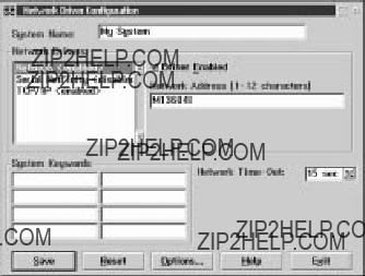
Follow these steps to continue configuring the system:
a.Enter a System Name.
Enter a name for the system in the System Name field. This name will help other Netfinity Manager users identify the system on the network.
b.Select a Network Driver.
Select one of the available Network Drivers that are displayed in the Network Drivers field. Once selected, the Network Driver will assign a network address to the system.
Notes:
(1)The fields that appear beneath the Driver Enabled check box will change depending on which Network Driver has been selected.
(2)When enabling the IPX or TCP/IP Network Driver, the network address cannot be altered, and it will not appear on the screen. No field will appear beneath the Driver Enabled check box if the IPX or TCP/IP Net- work Driver is selected.
(3)When enabling the NetBIOS Network Driver, a network address will be selected and dis- played in the Network Address field. To change this default name, enter any 1???8 character address. However, this address must be unique to the system. If this Net- BIOS address is identical to the NetBIOS address of another system on the network, it will prevent Netfinity Manager from starting properly.
(4)When enabling the Serial Netfinity Manager driver, type a name that will be used to iden- tify the system in the Unique Machine Dia- lup Name field. This name can be up to 32 characters long, and must be unique to the system. If this name is not unique, it can pre- vent remote Netfinity Manager users from
84 Netfinity 3500-M20 ??? Type 8657 Models 21Y, 22Y, 31Y, 32Y,
using the Serial Connection Control service to access the system.
c.Enable the Network Driver.
When all required information has been entered,
click the Driver Enabled check box to activate the driver on startup.
If the system supports multiple network interfaces, add additional network drivers by repeating steps b and c.
d.Identify the system with System Keywords (optional).
To make full use of the Remote System Man- ager???s discovery process, identify the system (and each of the Netfinity Manager systems that are on the network) with descriptive system keywords. Enter these keywords in the appropriate System Keywords fields.
e.Select Netfinity Manager Options (optional)
Click on the Options button to open the Netfinity Manager Options window. The Netfinity Manager Options window contains special options that affect Netfinity Manager network operations. Available options include:
???Force Remote Logons
If the Force Remote Logons option is enabled, the system will not be able to save the User ID/Password combinations that were used when accessing remote systems. This will force you to manually log on each time a remote system is accessed.
???Service Execution Alerts
If the Service Execution Alerts option is enabled, the Netfinity Manager Service Man- ager will generate a Netfinity Manager alert whenever one of the user???s Netfinity Man- ager services is started by a remote user. The alert includes the name of the service that was run and information about the user that started the service.
???Show Network Support
If the Show Network Support option is enabled, the Netfinity Manager Support Pro- gram (or Network Interface) will be visible as a minimized process in the Windows NT 4.0 task bar. This enables the user to shut down the Netfinity Manager Support Program. If the Netfinity Manager Support Program is to remain invisible to the user, do not enable this option.
???Remote User Authorization for Screen Access
If the Remote User Authorization for Screen Access option is enabled, a remote user cannot use either Remote Workstation Control or Screen View on your system with- out your permission. When this option is
enabled and a remote user attempts to use one of these services on your system, a win- dow will pop up on your desktop alerting you that a remote user is attempting to use the Remote Workstation Control or Screen View service and asking whether you want to per- mit this user to use this service on your sys- tem. You can click Yes or No. If you do not make a selection within 15 seconds (for example, if you are not sitting at your system when the access attempt is made), Netfinity Manager will automatically prevent the remote user from using the service on your system.
???Disable DNS Name Resolution
If the Disable DNS Name Resolution option is enabled, Netfinity Manager will use only a numeric TCP/IP address (for example, 8.24.67.32) to communicate with remote sys- tems and will not attempt to resolve the numeric address into an alphanumeric, Domain Name Server (DNS) address (for example, your.system.ibm.com). Select this option if you are using Netfinity Manager is a WINS networking environment or if you are using TCP/IP in an environment that does not have a Domain Name Server.
To enable one or more of the available Netfinity Manager Options:
(1)Click Options....
(2)Select one or more Netfinity Manager options.
(3)Click Save.
f.Set the Network Time-out Value (optional).
The Network Time-out field shows the number of seconds that Netfinity Manager will attempt to communicate with a remote system that is not responding. If Netfinity Manager does not estab- lish contact with the remote system within this time, it cancels the communication attempt. The Network Time-out default setting is 15 seconds. This default setting might not need to be altered.
g.Save the configuration and continue.
Click Save to save the configuration. Then, click Exit to continue.
Note: The configuration can be changed later by double-clicking the Network Driver Con- figuration object in the Netfinity Manager folder.
10.After finishing configuring the system for network access, the installation program displays a list of changes that must be made to the system configuration files, and asks whether the installation program should make the changes. For example, if Netfinity Manager for Windows 95 is being installed, the installation pro- gram will display a list of changes that must be made to the CONFIG.SYS file.
86 Netfinity 3500-M20 ??? Type 8657 Models 21Y, 22Y, 31Y, 32Y,

Click either Yes or No.
Note: These changes must be made to the system configuration for Netfinity Manager to run cor- rectly.
???If you click Yes the installation program automati- cally makes the necessary changes to the system configuration.
???If you click No the commands are saved to a file named CONFIG.NEW in the destination directory (and to AUTOEXEC.NEW, if appropriate) so that they can be added later.
11.The installation is now complete. Shut down and restart the system for the system configuration changes to take effect.
Netfinity Manager database support
Netfinity Manager supports the collection and export of a vast amount of system-specific data to a Netfinity Manager database.
Netfinity Manager databases can be created on database management systems using DB2??, Lotus Notes??, or Microsoft SQL. Microsoft SQL is supported through open database connectivity (ODBC), and is available on systems running Netfinity Manager for OS/2, Windows 95, or Win- dows NT. If the system supports ODBC, the user can access and export DB2 data through ODBC as well. Once support for one or more of these databases has been installed along with Netfinity Manager, data can be exported from these Netfinity Manager services:
???Alert Manager
???Software Inventory
???System Information Tool
???System Profile
???System Monitor
Information on how to install and configure support for data- base export follows.
???If support for DB2 database export is being installed, see ???DB2 database support???.
???If support for Lotus Notes database export is being installed, see ???Lotus Notes database support??? on page 91.
???If support for ODBC database export is being installed, see ???ODBC database support??? on page 93.
DB2 database support
Support for DB2 database export is automatically configured during installation of the Netfinity Manager. However, the database system itself must be configured. Instructions for configuring the database follow.
A raw data dump to a file is also available and will run with- out a database.
System requirements
Netfinity Manager DB2 database export is supported on systems running Netfinity Manager for OS/2, Netfinity Man- ager for Windows 95, Netfinity Manager for Windows 98, and Netfinity Manager for Windows NT. For more informa- tion about supported version numbers refer to Table 15 on page 97 and Table 16 on page 98.
Attention:
Using Netfinity Manager database support with systems run- ning unsupported versions of DB2 or the DB2 Client might cause unpredictable results and might halt the system.
See the DB2 Installation Guide for general requirements and supported protocols.
Installing and configuring the database
The following information describes the steps to install and configure the DB2 database.
Note: If your primary system is OS/2, refer to ???Installing the database on OS/2???.
1.Start a DB2 command window.
Note: If it is not already running, start the DB2 data- base manager.
2.Type the following command:
DB2 CREATE databasename ON d where
???databasename is the name of the database
???d is the drive where the database is created
3.Press Enter.
4.Next, you must configure the tables for ODBC data- base support. For information on configuring the data- base for ODBC, refer to ???ODBC database configuration??? on page 94. For information on creating the tables, refer to ???Creating the Netfinity Manager tables??? on page 95.
5.Finally, you must bind the database. For information on binding the database, refer to ???Activating the database??? on page 89.
Installing the database on OS/2:
1.Insert the Netfinity Manager CD into the CD-ROM drive (in this example, drive D; individual drive letters might be different).
2.Start an OS/2 window or full-screen session.
3.Make the CD-ROM drive the active drive. Type D: and then press Enter.
4.Type the following command at the OS/2 prompt:
NETFINDB CREATE /DBNAME=databasename /DRIVE=d
where databasename is the name of the database and d is the drive where the database will be located.
Note: If any part of the database already exists, the utility program will create only the portions of the database that are missing.
5.Press Enter.
88 Netfinity 3500-M20 ??? Type 8657 Models 21Y, 22Y, 31Y, 32Y,
Activating the database
The following information describes how to connect, bind, and grant privileges to the database.
1.Connecting to the Database
a.Start a DB2 command window.
b.Type the following command:
DB2 CONNECT TO databasename
where databasename is the name of the database as specified in the database installation step.
c.Press Enter.
2.Bind the package and the database
To prepare SQL statements stored in the bind file and store the package in the database, perform the follow- ing steps from a system on which Netfinity Manager for OS/2, Netfinity Manager for Windows 95, or Netfinity Manager for Windows NT has been installed:
a.Open a DB2 command window.
b.In the DB2 command window, type the following command:
DB2 BIND x:\directory\DB2SQLC0.bnd
where x:\directory is the name of the drive and directory where Netfinity Manager is installed.
c.Press Enter.
Granting and revoking database privileges
The following information describes how to grant and revoke database privileges.
Note: If your primary system is OS/2, refer to ???Database privileges on OS/2 systems??? on page 90.
1.Start a DB2 command window.
Notes:
a.If it is not already running, start the DB2 database manager.
b.If you are not connected to the DB2 Netfinity data- base connect to the database now.
2.Type the following command:
DB2 GRANT privilegecode ON TABLE tablename TO userid where
???privilegecode is one of the following privilege codes:
???ALL
???ALL PRIVILEGES
Note: Grants all the appropriate privileges, except CONTROL, on the database.
???ALTER
???CONTROL
???DELETE
???INDEX
???INSERT
???REFERENCES
???SELECT
???UPDATE
???tablename is the name of the table as specified during database installation. A listing of the Net-
finity database table names can be found in the Netfinity User???s Guide (Appendix H: Netfinity Rela- tional Database Tables).
Note: The Netfinity Database Administration Tool can also be used to GRANT or REVOKE privileges.
???userid is the user ID to be granted access
3.Press Enter to execute the command.
To revoke privileges, substitute REVOKE for GRANT in the command line.
Database privileges on OS/2 systems:
1.Use the GRANT EXECUTE command to enable Netfin- ity Manager to access the database.
Type the following command at the OS/2 prompt:
DB2 GRANT EXECUTE ON PACKAGE NETFIN.DB2SQLC0 TO
PUBLIC
and then press Enter.
Note: Specify PUBLIC or authorize only specific man- ager systems. To limit access to the database, substitute the authorization name of the manag- ing system for PUBLIC.
2.Use the CONNECT RESET command to disconnect current users from the database.
Type the following command at the OS/2 prompt:
DB2 CONNECT RESET and then press Enter.
3.Use the NETFINDB GRANT command to grant (or revoke) database privileges.
To grant or revoke table privileges on OS/2:
a.Insert the Netfinity Manager CD into the CD-ROM drive (in this example, drive D; individual drive let- ters might be different).
b.Make the CD-ROM drive the active drive. Type D: and then press Enter.
c.Type the following command:
NETFINDB GRANT /ID=id PUBLIC /DBNAME=databasename /PRIV=privilegecode
where
???id is the user ID to be granted access
???databasename is the name of the database as specified during NETFINDB execution
???privilegecode is one of the following privilege codes:
???ALL
???ALTER
???CONTROL
???DELETE
???INDEX
???INSERT
???REFERENCES
???SELECT
???UPDATE
d.Press Enter to execute the command.
90 Netfinity 3500-M20 ??? Type 8657 Models 21Y, 22Y, 31Y, 32Y,
Note: Use PUBLIC or authorize only a specific ID or group name. Netfinity Manager update programs use the DB2SQLC0 package and do not require specific table privileges.
To revoke privileges, substitute REVOKE for GRANT in the command line.
To configure Netfinity Manager to discontinue export data through ODBC for use on DB2, refer to ???ODBC database support??? on page 93.
Cataloging the database in the managing system: If the manager is using a remote database, cata- log the node the database resides on and then catalog the database to that node.
Once this step has been completed, the name of the Netfin- ity Manager database will appear in the System Information Tools Database Selection window.
Deleting the database
The following information describes how to delete the data- base for all supported operating systems.
Note: If your operating system is OS/2, refer to ???Deleting the database on OS/2???.
1.Start a DB2 command window.
2.Type
DB2 DROP DATABASE databasename where
databasename is the name of the database as specified during the database installation.
3. Press Enter.
Deleting the database on OS/2: 1.Insert the Netfinity Manager CD-ROM into the database server CD-ROM drive (in this example, the CD-ROM drive is E).
2.Start an OS/2 window or full-screen session.
3.Make the CD-ROM drive the active drive. Type E: and press Enter.
4.Type the following command at the OS/2 prompt:
NETFINDB DELETE /DBNAME=databasename
where databasename is the name of the database as specified during NETFINDB execution.
5.Press Enter.
To configure Netfinity Manager to discontinue export data through ODBC for use on DB2, refer to ???ODBC database support??? on page 93.
Lotus Notes database support
To enable the Netfinity Manager to export system data to a Lotus Notes database, the following must be done:
1.Install the Netfinity Manager database template on the Lotus Notes server.
2.Enable Netfinity Manager to export to the Lotus Notes server.
Instructions on installing the Lotus Notes database template and enabling the Netfinity Manager to export to the Lotus Notes database follow.
System requirements
The minimum requirements for Netfinity Manager to export data to a Lotus Notes database are:
???Lotus Notes
???Lotus Notes client
For information on what versions of Lotus Notes and the Lotus Notes client are supported, see Table 15 on page 97. See the Notes Administrator???s Guide for general system requirements and supported communications protocols.
Installing the database
To enable Netfinity Manager to export system data to a Lotus Notes database, install the Netfinity Manager data- base template on the Lotus Notes server. During Netfinity Manager installation, a Lotus Notes database template file (named NETFINDB.NTF) was copied to the Netfinity Man- ager program directory. To install the database template on the Lotus Notes server:
1.Copy NETFINDB.NTF from the Netfinity program direc- tory to the Notes data directory on the Lotus Notes server.
2.Start Lotus Notes on the server.
3.Click New Database... from the Notes File pull-down menu.
This opens the New Database window.
4.Click Netfinity Database from the Template selection list.
5.Check the Inherit Future Design Changes check box.
This enables future releases of Netfinity Manager to automatically apply changes to this Netfinity Manager database.
6.Click Local from the Servers selection list.
Note: When installing the database on a remote server, select the name of the remote server from the Servers list.
7.Type in the Filename field:
NETFINDB.NSF
8.Type in the Title field:
Netfinity Database
9.Click New to create the database and close the New Database window.
10.Double-click the Netfinity Database icon in the Lotus Notes workspace.
11.Click Database in the File pull-down menu.
12.Click Access Control... in the Database pull-down menu.
13.Set the Access Level for all Netfinity Manager systems that will be exporting data to this database to Editor.
14.Check the Can Delete Documents check box.
15.Click OK.
92 Netfinity 3500-M20 ??? Type 8657 Models 21Y, 22Y, 31Y, 32Y,
Once the Lotus Notes database is installed, enable Netfinity Manager systems to export to the Lotus Notes server.
???If the Netfinity Manager system is running Netfinity Manager for OS/2, ensure that the Lotus Notes directo- ries are included in the CONFIG.SYS file LIBPATH, PATH, and DPATH statements. If the directories are not included in these statements, it is not possible to export to the Lotus Notes database.
???If the system is running Netfinity Manager for Windows NT, ensure that the Lotus Notes directory path is included in the Global Windows NT environment set- tings.
???If the system is running Netfinity Manager for Windows 95, ensure that the Lotus Notes directories are included in the AUTOEXEC.BAT file PATH statement. If the directories are not included in this statement, it is not possible to export to the Lotus Notes database.
Once these steps have been completed, export system information from Netfinity Manager to an easy-to-browse Lotus Notes database.
Browsing the Netfinity Manager Lotus Notes database
To browse the data contained in the Netfinity Manager Lotus Notes database:
1.Open the Netfinity Database object in the Lotus Notes Workspace.
2.Select from the View pull-down menu the section of the Netfinity Manager database to be browsed.
The Netfinity Manager database is divided into sections that contain data gathered by specific Netfinity Man- ager services. Click the name of the service that gath- ers the data to be viewed (for example, Alert Logs).
Note: Some menu selections will contain submenus.
3.Information contained in the part of the Netfinity Man- ager database that has been selected is now listed in the window. For more detailed information about any displayed data item, double-click the data item.
4.Some data items can be expanded to reveal additional information. These items are identified by a plus sign
(+) in the left side border of the Notes window, beside the name of the data item. To expand the data item, select the item and then click Expand in the View pull- down menu.
ODBC database support
Netfinity Manager supports exporting data via ODBC for use on SQL or DB2 database systems.
Note: ODBC database export is available only on systems that are running Netfinity Manager.
System requirements
The minimum requirements for Netfinity Manager ODBC database export are:
???Windows NT
???ODBC
???ODBC support for one or more of the following database management systems (DBMS):
???IBM DB2
???Microsoft SQL Server
???Windows 95, with:
???ODBC
???ODBC support for one or more of the following database management systems:
???IBM DB2
???Microsoft SQL Server
???OS/2
???Microsoft SQL Server (using the Visigenic driver provided with Microsoft SQL Server)
or
??? IBM DB2
For detailed information about supported ODBC plat- forms, see Table 15 on page 97 and Table 16 on page 98.
Note: The ODBC database name must not be longer than 8 characters.
ODBC database configuration
This section describes the procedures you must complete before Netfinity Manager can create the Netfinity Database Tables using ODBC.
1.Define the NETFIN ID so the Netfinity Database Administration can create the Netfinity Database tables with a table qualifier of NETFIN.
Attention: NETFIN is a restricted user ID. The password is not retained by Netfinity Database Administration after use. Do not use this ID for exports.
Notes:
a.In OS/2 and Windows 95, NETFIN must either be the owner of the database or must be given administrator authority.
b.In Windows NT, when exporting to DB2, NETFIN must either be the owner of the database or be defined as a system administrator through the NT User Manager for Domains or the NT User Man- ager.
In Windows NT, when exporting to MS SQL, NET- FIN must be the owner of the database or be given table create rights.
2.Create the database with the appropriate relationship with the NETFIN ID.
3.Make a database ODBC source either using the ODBC tools shipped with the operating system or the data- base.
4.On Windows NT, configure the Netfinity Support Pro- gram to export data using the ODBC database.
a.Open Services from the Control Panel.
b.Click Netfinity Support Program from the Ser- vices field, then click Startup.
94 Netfinity 3500-M20 ??? Type 8657 Models 21Y, 22Y, 31Y, 32Y,
c.Click Automatic in the Startup Type button group.
d.Click This Account in the Log On As field group. Enter in the This Account field the user name of the account that made this database an ODBC source.
e.Click OK.
Note: If the Event Scheduler or Alert Manager will be used to export data using ODBC, continue to have the ID which made the database an ODBC source logged on during the time Event Scheduler will be exporting data.
Creating the Netfinity Manager tables
To create the tables needed to enable Netfinity Manager to export data:
1.Open the Netfinity Manager Database Administration service.
The Netfinity Manager Database Administration service is found in the Netfinity Manager folder or Netfinity Manager program group. Double-click this icon to open the Netfinity Manager Database Administration window.
2.Select a DBMS.
Click in the Select DBMS listing the name of the DBMS which Netfinity Manager will be using to export data.
3.To create the Netfinity Manager table groups within the database, click Create and then click OK to open the Database Server window.
The following table actions are also available:
???Delete
To remove the Netfinity Manager table groups from the database, click Delete and then click OK to open the Database Server window.
???Grant
Permits access to a database for a specified user ID. To grant access:
a.Click Grant.
b.In the User ID field type the user ID that will be permitted to access the database.
c.Select privileges for this ID.
All privileges (Insert, Delete, Select, and Update) are selected by default. A user ID must have all of these privileges to export data to the database.
d.Click OK to open the Database Server win- dow.
???Revoke
Disables access to a database for a specified user ID. To revoke access:
a.Click Revoke.
b.In the User ID field type the user ID that will have access to the database revoked.
c.Deselect privileges to be revoked for this ID.
All privileges (Insert, Delete, Select, and Update) are selected by default. A user ID must have all of these privileges to export data to the database. Some or all of these privileges can be revoked.
d.Click OK to open the Database Server win- dow.
4.Select the database within which the table groups will be created.
5.Click OK.
The Netfinity Manager Database Access window opens.
6.Type in the User ID field netfin
netfin is the qualifier name of the Netfinity Manager database.
7.In the Password field type the password that enables access to the Netfinity Manager database.
8.Click OK.
As the information is processed, a Creating tables status message should be displayed. When the operation com- pletes, a Requested Action Completed message should be displayed.
96 Netfinity 3500-M20 ??? Type 8657 Models 21Y, 22Y, 31Y, 32Y,
Supported and certified databases
The following tables show databases and operating systems that are certified for use with this release of Netfinity Man- ager.
Table 15. Supported Netfinity Databases for Windows.
Reference by operating system and database client version.
Table 15. Supported Netfinity Databases for Windows.
Reference by operating system and database client version.
Note: The above applies to Netfinity Manager Release 5.2.0 and later.
Table 16. Supported Netfinity Databases for OS/2.
Reference by operating system and database client version.
98 Netfinity 3500-M20 ??? Type 8657 Models 21Y, 22Y, 31Y, 32Y,
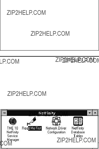
Table 16. Supported Netfinity Databases for OS/2.
Reference by operating system and database client version.
Note: The above applies to Netfinity Manager Release 5.2.0 and later.
Starting Netfinity Manager
To start Netfinity Manager:
1.Open the Netfinity Manager folder or program group.
During installation of Netfinity Manager, a Netfinity Manager folder (OS/2, Windows 95, or Windows NT 4.0 only) or a Netfinity Manager program group (Win- dows NT 3.51 only) was added to the Desktop. The Netfinity Manager folder or program group contains the Netfinity Manager Service Manager object.
Notes:
a.In your Netfinity Manager folder or program group is a document titled Read Me First, which contains information about Netfinity Manager that might not be covered in your documentation.
b.The Netfinity Manager folder also contains the Network Driver Configuration object, which you can use to reconfigure your network protocols and system keywords, and the Netfinity Manager Database Tables object, which contains a handy online reference for all of the data tables in the Netfinity Manager database. For more information on Netfinity Manager database support see ???Net- finity Manager database support??? on page 87.
c.The Netfinity Manager folder also contains a Net- finity Database Administration object. You can use Netfinity Database Administration to configure Netfinity Manager database support. For more

information on Database Administration, see "ODBC Database Support" in Netfinity Manager Quick Beginnings.
2.Start the Netfinity Service Manager.
To start the Netfinity Service Manager, double-click the Netfinity Service Manager object.
Netfinity Manager Service Manager
All Netfinity Manager services that are supported by the operating system can be started from the Netfinity Manager Service Manager window. The services that are available for use depend on the installation configuration that was selected during installation.
To start any Netfinity Manager service that appears in the Service Manager window, double-click the icon for that ser- vice. To start a Netfinity Manager service on a remote sys- tem, use the Remote System Manager service.
Netfinity Manager service descriptions
Each Netfinity Manager service consists of a base program and a graphical user interface (GUI). The service base pro- grams enable Netfinity Manager to remotely access the indi- vidual services, but do not allow for local access. The service GUIs, when functioning along with their respective base program, enable access to the service.
Some services are available only on systems with certain system configurations. These services are:
???Alert on LAN Configuration (available only on systems running Windows 95 or later or Windows NT 4.0 or later)
???Capacity Management (available only on systems run- ning Windows NT 4.0 or later)
???Cluster Manager (available only on systems running Windows NT 4.0 or later)
???DMI Browser (requires DMI Service Layer)
???ECC Memory Setup (requires ECC memory)
???Predictive Failure Analysis (requires a PFA-enabled hard disk drive)
100 Netfinity 3500-M20 ??? Type 8657 Models 21Y, 22Y, 31Y, 32Y,
???RAID Manager (requires a RAID hard disk drive sub- system)
???System Partition Access (requires a built-in System Partition)
???Update Connector Manager (available only on systems running Windows NT 4.0 or later)
Brief descriptions of each of the Netfinity Manager services follow. Complete instructions on how to use each of these services can be found in the service-specific chapters of the
Netfinity Manager User???s Guide.
Alert Manager
The Alert Manager is an extendable facility that allows receiving and processing of application-generated alerts. A variety of actions can be taken in response to alerts, includ- ing logging alerts, notifying the user, forwarding the alert to another system, executing a program, playing a WAV file (available only on multimedia systems), generating an SNMP alert message, dialing out to a digital pager service (available only on systems that have a modem), or taking an application-defined action. Actions are user-definable, using a flexible action management interface.
Also, an extensive, detailed log is kept of all alerts received by the Alert Manager. Logged information includes date and time the alert was received, type and severity of the alert, the ID of the application that generated the alert, as well as any text that was generated and any action taken by the Alert Manager. Individual or multiple alerts can be selected from the log and printed for later reference, or deleted once problems are corrected. This service is available for stand- alone use and network use.
Alert on LAN configuration
Use the Alert on LAN configuration service to configure monitoring options of Alert on LAN-capable systems locally and remotely. Systems with Alert on LAN capability provide critical status information about system states. The data is reported by hardware or software (depending upon whether the systems in currently powered on or not) using TCP/IP.
Capacity Management
Capacity Management is an easy-to-use resource manage- ment and planning tool for network managers and adminis- trators, allowing you to remotely monitor the performance of servers on the network.
Cluster Manager
Cluster Manager is an application designed to enhance the cluster management capabilities of the Microsoft Cluster Server (MSCS) administration console, included with Microsoft Windows NT Version 4.0 Enterprise Edition. Clus- ter Manager builds on the power of MSCS, providing an inte- grated graphical interface that enables you to quickly and easily monitor and manage the clustered systems on your network. This service is available only on systems running Windows NT Workstation 4.0.
Critical File Monitor
Critical File Monitor can warn you whenever critical system files on the system are deleted or altered. Critical File Moni- tor makes it simple to generate Netfinity alerts when an important System File (such as the CONFIG.SYS file) changes date, time, size, or when it is deleted or created. Critical File Monitor can also be used to monitor any other files that reside on a Netfinity Manager system.
DMI Browser
DMI Browser enables you to examine information about the DMI-compliant hardware and software products installed in or attached to the system.
ECC Memory Setup
The ECC Memory Setup allows for monitoring of ECC mem- ory single-bit errors, and can automatically "scrub," or cor- rect, the ECC memory when errors are detected. Also, a running count of single-bit errors can be kept, and can set a single-bit error threshold that will cause a nonmaskable interrupt (NMI) if the ECC single-bit error threshold is exceeded. This service is available for both stand-alone and network use by any system that has ECC memory.
Event Scheduler
Use Event Scheduler to automate many Netfinity Manager services. With Event Scheduler, you can automatically gather and export System Information Tool, System Profile, and Software Inventory data, distribute or delete files, restart systems, execute commands, and access and manage Sys- tem Partitions on all of the Netfinity Manager systems on the network. Scheduled events can be performed one time only, or can be performed according to a user-defined schedule.
File Transfer
Use the File Transfer service to easily send, receive, or delete files or entire directories to and from remote Netfinity Manager systems on the network.
Power-On Error Detect
The Power-On Error Detect service can warn you immedi- ately when a remote Netfinity Manager system has start-up problems, enabling you to react quickly to problems and minimize downtime.
Predictive Failure Analysis
The Predictive Failure Analysis (PFA) service enables con- tinual monitoring and managing of PFA-enabled hard disk drives. A PFA-enabled hard disk drive features hardware designed to help detect drive problems and predict drive fail- ures before they occur, thus enabling you to avoid data loss and system downtime.
Process Manager
Use Process Manager to view detailed information about all processes that are currently active on any system. It is also possible to stop or start processes and generate Netfinity Manager alerts if a process starts, stops, or fails to start within a specified amount of time after system startup.
RAID Manager
The RAID Manager service can monitor, manage, and con- figure an assortment of Redundant Arrays of Independent
102 Netfinity 3500-M20 ??? Type 8657 Models 21Y, 22Y, 31Y, 32Y,
Disk (RAID) adapters and arrays without requiring the RAID system to be taken offline to perform maintenance. Use the RAID Manager to gather data about the system RAID array and RAID adapter, rebuild failing drives, add (or remove) logical drives, perform data integrity tests, and many other RAID system tasks. This service is available for stand-alone use and network use by any system that has a supported RAID adapter.
Remote Session
Use Remote Session to establish a fully active command session with any remote Netfinity Manager system.
Remote System Manager
Use Remote System Manager to access and manage any Netfinity Manager service on any Netfinity Manager system in the network. The Netfinity Manager system on the net- work is organized into easy-to-manage logical groups that can be updated automatically using the auto-discovery fea- ture.
Remote Workstation Control
Remote Workstation Control can monitor or control the screen display of a remote system that is running Netfinity Manager (or Client Services for Netfinity Manager). Once you initiate a Remote Workstation Control session with another Netfinity Manager system, you can passively moni- tor events that are occurring on the display of the remote system or actively control the remote system desktop. When you initiate an active Remote Workstation Control session, all clicks and keystrokes that are entered on your system are automatically passed to the remote system. With Remote Workstation Control, you can remotely start programs, open and close windows, enter commands, and much more.
Screen View
The Screen View service takes a "snapshot" of the system graphic display or any remote system running Netfinity Man- ager or Client Services for Netfinity Manager and displays it on the screen. These snapshots can be saved as bitmaps and viewed later.
Security Manager
The Security Manager service can prevent unauthorized access to some or all of the Netfinity Manager services. It uses incoming user ID and password combinations, and is available for network use only.
Serial Connection Control
The Serial Connection Control service enables remote sys- tems running Netfinity Manager to access the system through a phone line and modem. With the Serial Connec- tion Control service, you do not have to be attached to a net- work to benefit from the outstanding remote system access, monitoring, and management capabilities of Netfinity Man- ager.
Note: The system must have a properly installed and con- figured modem that supports at least 9600 baud for the Serial Connection Control service to function.
Service Configuration Manager
Service Configuration Manager can save the configuration of a Netfinity Manager service from a selected system to a service configuration file (SCF). Once created, SCF files can be used by Event Scheduler to restore the configuration to the same system, or it can be used (in conjunction with Event Scheduler) to duplicate that configuration on other similar systems you choose.
Software Inventory
Software Inventory enables the user to create and manage software product dictionaries that can be used to easily maintain an inventory of all application programs installed on the system.
System Diagnostics Manager
System Diagnostics Manager enables you to initiate a vari- ety of diagnostic tasks on systems that support ROM-based diagnostics. The results of all previously run diagnostic ses- sions are stored and can be examined using System Diag- nostics Manager to help diagnose and resolve system problems.
System Information Tool
The System Information Tool enables quick and convenient access to detailed information on the hardware and software configurations of the system. System Information Tool gath- ers information about almost any computer; however, the most detail is provided when this service is used with IBM computers. This service is available for both stand-alone and network use.
System Monitor
The System Monitor provides a convenient method of chart- ing and monitoring the activity of a number of components in a system, including processor usage, disk space used, and ECC memory errors. These convenient monitors are detachable and scalable, enabling only the monitors needed to remain available at all times. Use the System Monitor Threshold Manager to set threshold levels for any of the monitored components. When exceeded, these thresholds will generate user-configured alerts.
Data is continually collected from the time the system starts. A sophisticated data-handling technique is used to weigh the individual values, average concurrent samples, and post sin- gle values that accurately reflect long-term system activity.
This technique allows system activity records to be main- tained without creating enormous data files. This service is available for both stand-alone and network use.
System Partition Access
The System Partition Access allows for greatly simplified system partition file handling, both locally and remotely. Individual files and entire directories can be renamed or deleted from the system partition. Individual files can be renamed, deleted, or copied into the system partition. Also, the entire partition can be backed-up, restored, or deleted. This service is available for stand-alone use and network use by any system that has a System Partition.
104 Netfinity 3500-M20 ??? Type 8657 Models 21Y, 22Y, 31Y, 32Y,
System Profile
The System Profile provides a convenient notebook of perti- nent data about a particular user or system. It features many predefined fields for extensive user-specific data, including name, address, office number and location, and phone number. System Profile also includes many pre- defined fields for system-specific data that might not be available to the System Information Tool, including model and serial numbers and date of purchase. Finally, there are many user-definable miscellaneous fields that can be used to hold any data the user or administrator requires.
Update Connector Manager
Use Update Connector Manager to quickly and easily gather information about various updates that are available for your client systems. Once available updates are discovered, use Update Connector Manager to apply updates to your sys- tems remotely. Updates can be applied to individual sys- tems, or you can apply multiple updates to multiple systems, all from Netfinity Manager. You can also use Update Con- nector Manager to remove previously applied updates. Update Connector Manager also includes a scheduler that you can use to discover, apply, or remove updates automati- cally and periodically.
Web Manager Configuration
Use the Web Manager Configuration service to limit access to the Netfinity Manager for Web to user-specified TCP/IP host or ranges of TCP/IP host addresses. Enable or disable the Netfinity Manager for Web and specify the TCP/IP port number to which the Netfinity Manager Web server func- tions.
Delaying Netfinity Manager startup on OS/2 systems
In some cases, it might be necessary for you to delay the automatic startup of the Netfinity Manager Network Interface (NETFBASE.EXE) in order to allow other time-sensitive applications to start up correctly or to allow your system to fully configure itself prior to beginning network operations. NETFBASE.EXE includes a parameter (WAIT) that you can use to specify the number of seconds that NETFBASE.EXE will wait before starting.
During Netfinity Manager installation, the Netfinity Manager Network Interface object is placed in the Startup folder. To configure Netfinity Manager to wait a specified number of seconds before starting:
1.Shut down the Netfinity Manager Network Interface if it is running.
2.Open the Startup folder.
3.Using the right mouse button, click the Netfinity Man- ager Network Interface object. This will open the Net- finity Manager Network Interface context menu.
4.Click Settings to open the Netfinity Manager Network Interface Settings notebook.
5.In the Parameters field type
WAIT:x
where x is the number of seconds that you want the Netfinity Manager Network Interface to wait before starting.
6.Close the Netfinity Manager Network Interface Set- tings notebook.
With the WAIT parameter set to x, whenever you start your system, the Netfinity Manager Network Interface will wait x seconds before starting.
Note: This feature is available only on systems that are run- ning OS/2.
Getting more information about Netfinity Manager
Complete information on how to use Netfinity Manager (as well as Client Services for Netfinity Manager) is included in Adobe Acrobat format on the Netfinity Manager CD.
The \DOCS subdirectory contains the following files:
106 Netfinity 3500-M20 ??? Type 8657 Models 21Y, 22Y, 31Y, 32Y,

Installation options
This appendix describes methods for performing automated installations of Netfinity Manager and creating customized Netfinity Manager installations.
Automated installation
If the system has a CID-enabled (CID stands for customiza- tion, installation, and distribution) software distribution man- ager utility (such as LAN CID, included with IBM Network Transport Services/2), Netfinity Manager can be installed on systems within the network by using the Netfinity Manager installation program command line parameters and response file. First, a source directory must be created for the installation.
To create a source directory for a Client Services for Netfinity Manager installation:
1.Create a new directory on your system. This new directory will serve as a source directory for the pro- gram files.
2.Copy the files from the appropriate Client Services for Netfinity Manager directory location on the CD-ROM to source directory you created.
For example, when creating a source directory to dis- tribute Netfinity Manager Services for OS/2, copy all of the files from the OS2/SERVICES directory into the created directory.
To create a source directory for a Netfinity Manager installa- tion:
1.Create a new directory on your system. This new directory will serve as a source directory for the pro- gram files.
Important:
Be sure to copy the Client Services for Netfinity Man- ager source files before the copying the Netfinity Man- ager source files because the Netfinity Manager directory contains some files that will overwrite files from the Client Services for Netfinity Manager directory. Only Netfinity Manager installations can be done from this directory.
2.Copy the files from the appropriate Client Services for Netfinity Manager directories.
For example, when creating a source directory to dis- tribute Netfinity Manager for OS/2, copy all of the files from the OS2/SERVICES directory into the source directory.
3.Copy the files from the appropriate Netfinity Manager directory.
For example, when creating a source directory to dis- tribute Netfinity Manager for OS/2, copy all of the files from the OS2/MANAGER directory into the source directory.
After an installation source directory has been created, use a response file and the Netfinity Manager installation pro-
108 Netfinity 3500-M20 ??? Type 8657 Models 21Y, 22Y, 31Y, 32Y,
gram command-line parameters. The Netfinity Manager installation program supports the following command-line parameters:
/R: drive+path+filename
Specifies the drive, path, and file name of the response file. See the NETFBASE.RSP file (located in the direc- tory in which Netfinity Manager was installed) for an example of a response file with comments on the included parameters.
/S: drive+path
Specifies the drive and path to install from. This is the directory to which the files were copied.
/T: drive
Specifies the drive to install to. Default is the current startup drive.
/TU: drive+path
Specifies the drive and path of the CONFIG.SYS file to update. The default is to change the CONFIG.SYS in the root directory of the drive specified in the /T param- eter (or the startup drive). This parameter is ignored if the ChangeConfig parameter in the response file is
FALSE.
For example, the line:
NETFINST /R:NETFBASE.RSP /S:Y:\NETFIN /T:C /TU:D:\
will install Netfinity Manager, using the options in the response file NETFBASE.RSP, from the directory Y:\NETFIN, to drive C: (the directory to which the files are installed is taken from the response file), and will modify the CONFIG.SYS file in the D:\ directory.
Note: For information on how to use a CID-enabled soft- ware distribution manager, refer to the publications provided with the individual CID-enabled product.
Customized installation
For security reasons, not all users might need to have access to all services. User access can be restricted by cre- ating a customized installation that will prevent some ser- vices from being installed.
To create a customized installation, the INSTALL.INI file must be edited. For example, when creating a customized Netfinity Manager for Windows 95 or NT installation, edit the INSTALL.INI file that is found on Netfinity Manager directory.
The INSTALL.INI file has three sections, separated by the line
[==]
The first section contains the installation configuration that can be selected during installation. There can be no more than eight choices. Each choice takes up two lines. The first line is the text that is displayed next to the installation configuration radio button. The second line is a list of the options in the third section that will be installed when this choice is selected for installation.
For example:
;IBM SysMgt Install Script, Version 2 (Do not remove this comment line)
Netfinity Manager Installation [Manager 16900] Advanced System Management Support [ServProc 450] Capacity Manager Enhancement [CapMgt 5600]
Remote Workstation Control [RWC 2000]
World Wide Web Enhancement (TCPIP Required) [WebManager 3000] IsTcpip
[==]
Netfinity Manager CD for Windows 95/NT [==]
NetFinity Admin NULL Manager
CL 0 1 NETFBASE.EXE
CCL 0 1 NETDOM.INI
CCL 0 1 NETNODES.INI
CCL 0 1 INSTALL.BAT
CCL 0 1 NETFINST.EXE
CCL 0 1 INSTALL.INI
CCL 0 1 WININST.HLP
CL 0 1 APCKINST.DLL ;Screen Capture GUI ;NULL Manager
;CL 0 1 SAVEG.EXE
;CL 0 1 SAVEG.HLP
This INSTALL.INI will create a Netfinity Manager installation configuration that also installs Advanced System Manage- ment, Capacity Manager, Remote Workstation Control, and Netfinity Manager World Wide Web enhancement.
The second section contains the names of the CD that this installation script will use.
The third section contains the list of options that can be installed. These are the options that are selected by the choices in the first section. The options are consecutively numbered starting at 1, so any inserted options will change the number of all following options. Each option uses the fol- lowing format:
Option Name
Dll-entrypoint
option file option file
...
install command
install command
...
Option Name An identifying comment by the installa- tion program. All options must have a different Option Name. This is used only for identification.
Dll-entrypoint Used to determine whether an option is valid for a given target machine. In
110 Netfinity 3500-M20 ??? Type 8657 Models 21Y, 22Y, 31Y, 32Y,
most cases, it should be the reserved string "NULL."
The easiest way to customize an installation is to simply put a semicolon in front of any service that you want to remove from the installation.
To add a line item in a specific section, add all the necessary item information in the format shown in the following exam- ple.
Before:
Screen Capture GUI
NULL Manager
CL 0 1 SAVEG.EXE
CL 0 1 SAVEG.HLP
After:
Screen Capture GUI
NULL Manager
CL 0 1 SAVEG.EXE
CL 0 1 SAVEG.HLP
CL 0 1 CUSTOM.INI
112 Netfinity 3500-M20 ??? Type 8657 Models 21Y, 22Y, 31Y, 32Y,
FRU information (service only)
Field Replacement Units (FRUs) should be replaced by qualified service personnel only.
Top cover
Before you begin:
???Read ???Safety information??? on page 155.
???Review the information in ???Before you begin??? on page 43.
??1?? Top cover
To remove the top cover, do the following:
1.Power-off the server, if it is on.
2.Unplug the server.
3.Using a screwdriver, gently pry the left side of the cover up.
4.Remove the cover.
114 Netfinity 3500-M20 ??? Type 8657 Models 21Y, 22Y, 31Y, 32Y,
FRU information (service only) 115
??1?? Chassis
??2?? Main bezel
To remove the main bezel, do the following:
1.Power-off the server, if it is on.
2.Unplug the server.
3.Remove the top cover by gently prying up the tabs on the left side.
4.Remove the bezel assembly (see ???Bezel assembly??? on page 114) and all filler panels on the front of the server.
5.Remove the left-side cover (see ???Removing the side cover??? on page 44.
6.Remove the CD-ROM drive screws (see ???CD-ROM drive??? on page 124) and put them in a safe place.
7.Gently push the CD-ROM drive toward the rear of the server.
8.Remove the floppy disk drive screws (see ???Floppy disk drive??? on page 123) and put them in a safe place.
9.Gently push the floppy disk drive toward the rear of the server.
116 Netfinity 3500-M20 ??? Type 8657 Models 21Y, 22Y, 31Y, 32Y,
10.Using a screwdriver, gently pry the top of the bezel away from the server.
11.Slide the main bezel down and gently pull away from the server.
12.To reinstall the bezel:
a.Align the prongs in the main bezel with the notches on the front of the server.
Note: It may be necessary to place the front of the server near the edge of a flat surface because the main bezel will extend slightly below the server until it is pushed up into position.
b.Slide the main bezel up.
c.Press in on the tabs on top of the bezel until they snap into place.
13.Slide the CD-ROM and floppy disk drives back into position and replace the screws.
Power/LED card
Before you begin:
???Read ???Safety information??? on page 155.
???Review the information in ???Before you begin??? on page 43.
FRU information (service only) 117
??1?? Screws
??2?? Power/LED card
To remove the power/LED card, do the following:
1.Power-off the server, if it is on.
2.Unplug the server.
3.Remove the top cover (see ???Top cover??? on page 113).
4.Pull the power/LED cable toward the right side of the server until it is free from its housing.
Note: Avoid allowing the cable to fall through the slot to the inside of the server.
5.Remove the screws.
6.Remove the power/LED card.
7.To install the new power/LED card, reverse the above steps.
Adapter card guide
Before you begin:
???Read ???Safety information??? on page 155.
???Review the information in ???Before you begin??? on page 43.
Note: This illustration depicts the server in the upright posi- tion. It is recommended that the server be placed on its left side before performing this service procedure.
118 Netfinity 3500-M20 ??? Type 8657 Models 21Y, 22Y, 31Y, 32Y,

??1?? Release tabs
??2?? Card guide
To remove the card guide, do the following:
1.Power-off the server, if it is on.
2.Unplug the server.
3.Remove the left-side cover (see ???Removing the side cover??? on page 44.
4.Turn the server onto its right side so that the open left side is facing up.
Note: Rotate the feet in toward the server so they do not detach due to the weight of the server.
5.Remove the support bracket (see ???Removing the sup- port bracket??? on page 45) and air baffle.
6.Press the release lever in the center of the card guide assembly to release the adapter cards.
7.Remove all adapter cards.
8.Detach cables from the system board.
9.Press down on the release tabs and tilt the top of the assembly toward the back of the server.
10.Pull the assembly away from and out of the server.
11.Remove the fan from the assembly:
a.Gently pull the fan assembly away from the card guide.
b.Pull the rubber extensions through the apertures.
12.Install the fan in the new assembly:
a.Align the rubber extensions in the fan assembly with the apertures in the card guide and gently press the fan into place.
b.Use needle-nosed pliers to pull the rubber exten- sions through the apertures.
13.Install the assembly in the server:
a.Insert the two tabs on the bottom of the card guide into the slots on the server.
b.Gently push the two release tabs through the notches until they click into place.
c.Reconnect cables.
Fan assembly, 92 mm
Before you begin:
???Read ???Safety information??? on page 155.
???Review the information in ???Before you begin??? on page 43.
FRU information (service only) 119

??1?? Rubber extensions
??2?? 92 mm fan assembly
To remove the 92mm fan assembly, do the following:
1.Power-off the server, if it is on.
2.Unplug the server.
3.Remove the left-side cover (see ???Removing the side cover??? on page 44.
4.Turn the server onto its right side so that the open left side is facing up.
Note: Rotate the feet in toward the server so they do not detach due to the weight of the server.
5.Remove the support bracket (see ???Removing the sup- port bracket??? on page 45) and air baffle.
6.Remove all adapter cards (see ???Working with adapters??? on page 45).
7.Detach cables from the system board.
8.Remove the card guide (see ???Adapter card guide??? on page 118).
9.Remove the fan from the assembly:
a.Gently pull the fan assembly away from the card guide.
b.Pull the rubber extensions through the apertures.
10.Install the new fan in the assembly:
a.Align the rubber extensions in the fan assembly with the apertures in the card guide and gently press the fan into place.
b.Use needle-nosed pliers to pull the rubber exten- sions through the apertures.
11.Replace the assembly in the server:
a.Insert the two tabs on the bottom of the card guide into the slots on the server.
120 Netfinity 3500-M20 ??? Type 8657 Models 21Y, 22Y, 31Y, 32Y,
b.Gently push the two release tabs through the notches.
12.Reconnect the cables.
13.Replace adapters.
Fan assembly, rear
Before you begin:
???Read ???Safety information??? on page 155.
???Review the information in ???Before you begin??? on page 43.
Note: This illustration depicts the server in the upright posi- tion. It is recommended that the server be placed on its left side before performing this service procedure.
3500
Netfinity
??1?? Rubber extensions
??2?? Rear fan assembly
To replace the rear fan assembly, do the following:
1.Power-off the server, if it is on.
2.Unplug the server.
3.Remove the left-side cover (see ???Removing the side cover??? on page 44.
4.Turn the server onto its right side so that the open left side is facing up.
Note: Rotate the feet in toward the server so they do not detach due to the weight of the server.
5.Remove the support bracket (see ???Removing the sup- port bracket??? on page 45) and air baffle.
6.Remove the fan cable from the system board.
FRU information (service only) 121
7.Use side cutters to sever the four rubber extensions on the outside of the server.
8.Gently pry the fan away from the server and lift it up and out.
9.To install the new fan assembly, place the fan in posi- tion at the rear of the server .
10.Guide the rubber extensions through the apertures.
11.Use needle-nosed pliers to pull the extensions through the apertures.
12.Reconnect cables.
Fan, hard disk drive
Before you begin:
???Read ???Safety information??? on page 155.
???Review the information in ???Before you begin??? on page 43.
Note: This illustration depicts the server in the upright posi- tion. It is recommended that the server be placed on its left side before performing this service procedure.
??1?? Rubber extensions
??2?? Fan assembly
To remove the hard disk drive fan assembly, do the follow- ing:
1.Power-off the server, if it is on.
2.Unplug the server.
122 Netfinity 3500-M20 ??? Type 8657 Models 21Y, 22Y, 31Y, 32Y,
FRU information (service only) 123
??1?? Screws
??2?? Floppy disk drive
To remove the floppy disk drive, do the following:
1.Power-off the server, if it is on.
2.Unplug the server.
3.Remove the left-side cover (see ???Removing the side cover??? on page 44).
4.Turn the server onto its right side so that the open left side is facing up.
Note: Rotate the feet in toward the server so they do not detach due to the weight of the server.
5.Remove the support bracket (see ???Removing the sup- port bracket??? on page 45) and air baffle.
6.Remove the floppy disk drive cable(s) from the system board.
7.Remove the two screws from the floppy drive housing.
8.Slide the floppy drive toward the front of the server and lift it out.
9.To replace the floppy drive, reverse the above steps.
CD-ROM drive
Before you begin:
???Read ???Safety information??? on page 155.
???Review the information in ???Before you begin??? on page 43.
124 Netfinity 3500-M20 ??? Type 8657 Models 21Y, 22Y, 31Y, 32Y,
Note: This illustration depicts the server in the upright posi- tion. It is recommended that the server be placed on its left side before performing this service procedure.
??1?? Screws
??2?? CD-ROM drive
To remove the CD-ROM drive, do the following:
1.Power-off the server, if it is on.
2.Unplug the server.
3.Remove the left-side cover (see ???Removing the side cover??? on page 44.
4.Turn the server onto its right side so that the open left side is facing up.
Note: Rotate the feet in toward the server so they do not detach due to the weight of the server.
5.Remove the support bracket (see ???Removing the sup- port bracket??? on page 45) and air baffle.
6.Remove the CD-ROM drive cable(s) from the system board.
7.Remove the two screws from the CD-ROM drive hous- ing.
Note: The screws are inserted in a staggered arrange- ment.
8.Slide the CD-ROM drive toward the front of the server and lift it out.
9.To replace the CD-ROM drive, reverse the above steps.
FRU information (service only) 125
Power supply
Before you begin:
???Read ???Safety information??? on page 155.
???Review the information in ???Before you begin??? on page 43.
Note: This illustration depicts the server in the upright posi- tion. It is recommended that the server be placed on its left side before performing this service procedure.
??1?? Screws
??2?? Power supply
To remove the power supply, do the following:
1.Power-off the server, if it is on.
2.Unplug the server.
3.Remove the left-side cover (see ???Removing the side cover??? on page 44.
4.Turn the server onto its right side so that the open left side is facing up.
Note: Rotate the feet in toward the server so they do not detach due to the weight of the server.
5.Remove the support bracket (see ???Removing the sup- port bracket??? on page 45) and air baffle.
126 Netfinity 3500-M20 ??? Type 8657 Models 21Y, 22Y, 31Y, 32Y,
6.Remove all cables.
7.Remove screws and lift power supply out of the server.
Planar with heatsinks
Before you begin:
???Read ???Safety information??? on page 155.
???Review the information in ???Before you begin??? on page 43.
Note: This illustration depicts the server in the upright posi- tion. It is recommended that the server be placed on its left side before performing this service procedure.
??1?? Screws
??2?? Planar
To remove the planar with heatsinks, do the following:
1.Power-off the server, if it is on.
2.Unplug the server.
3.Remove the left-side cover (see ???Removing the side cover??? on page 44.
4.Turn the server onto its right side so that the open left side is facing up.
Note: Rotate the feet in toward the server so they do not detach due to the weight of the server.
5.Remove the support bracket (see ???Removing the sup- port bracket??? on page 45) and air baffle.
FRU information (service only) 127
6.Remove the hard disk drive cage (see ???Installing a hard disk drive in bays E, F, or G??? on page 53).
7.Remove the adapter cards and place them on a static- protected surface (see ???Working with adapters??? on page 45).
8.Remove the memory cards and place them on a static- protected surface (see ???Installing memory-module kits??? on page 54).
9.Remove the voltage regulator module (see 9b on page 59).
10.Detach all cables.
11.Remove any heatsinks:
Note: A thermal material is used between the heatsink and the processor. This material when heated and cooled causes the heatsink to adhere to the processor. Some force may be required to remove the heatsink.
a.Press the handle of the heatsink clip down and toward the back until it releases, and lift it up and off the heatsink.
b.Firmly grasp heat sink and pull upward.
Attention: Do not use excessive force or tools to remove the heatsink.
c.Discard the used heatsink.
12.Remove all microprocessors and/or terminator card:
a.Lift the release lever.
b.Gently pull the microprocessor or terminator card and place it in a static-protected location.
13.Remove the planar screws.
14.Lift the planar out of the server.
128 Netfinity 3500-M20 ??? Type 8657 Models 21Y, 22Y, 31Y, 32Y,

Symptom-to-FRU index
This index supports Netfinity 3500-M20 ??? Type 8657 serv- ers.
Notes:
1.Check the configuration before you replace a FRU. Configuration problems can cause false errors and symptoms.
2.The default configuration can be loaded by starting the system and then pressing the reset button four times, waiting 15 seconds between each press. Once the configuration has reset to the default, it must be saved in Setup to be stored in CMOS.
3.For IBM devices not supported by index, refer to the manual for that device.
4.Always start with ???General checkout??? on page 1.
The Symptom-to-FRU lists symptoms, errors, and the possi- ble causes. The most likely cause is listed first. Use this Symptom-to-FRU index to help you decide which FRUs to have available when servicing the computer. The POST BIOS displays POST error codes and messages on the screen.
Beep symptoms
Beep symptoms are short tones or a series of short tones separated by pauses (intervals without sound). See the fol- lowing examples.
Note: One beep after successfully completing POST indi- cates the system is functioning properly.
130 Netfinity 3500-M20 ??? Type 8657 Models 21Y, 22Y, 31Y, 32Y,
132 Netfinity 3500-M20 ??? Type 8657 Models 21Y, 22Y, 31Y, 32Y,
No beep symptoms
Diagnostic error codes
Note: In the following error codes, if XXX is 000, 195, or 197do not replace a FRU. The description for these error codes are:
000 The test passed.
195 The Esc key was pressed to abort the test.
197This is a warning error and may not indi- cate a hardware failure.
For all error codes, replace/follow the FRU/Action indicated.
134 Netfinity 3500-M20 ??? Type 8657 Models 21Y, 22Y, 31Y, 32Y,
136 Netfinity 3500-M20 ??? Type 8657 Models 21Y, 22Y, 31Y, 32Y,
138 Netfinity 3500-M20 ??? Type 8657 Models 21Y, 22Y, 31Y, 32Y,
140 Netfinity 3500-M20 ??? Type 8657 Models 21Y, 22Y, 31Y, 32Y,
POST error codes
In the following error codes, X can be any number or letter.
142 Netfinity 3500-M20 ??? Type 8657 Models 21Y, 22Y, 31Y, 32Y,
144 Netfinity 3500-M20 ??? Type 8657 Models 21Y, 22Y, 31Y, 32Y,
146 Netfinity 3500-M20 ??? Type 8657 Models 21Y, 22Y, 31Y, 32Y,
ServeRAID
For ServeRAID error codes and procedures, refer to the Hardware Maintenance Manual for the particular RAID adapter in the system being serviced.
Undetermined problems
You are here because the diagnostic tests did not identify the failure, the Devices List is incorrect, or the system is inoperative.
Note: A corrupt CMOS can cause undetermined problems.
If power problems are suspected:
1.Power-off the computer.
2.Be sure the system is cabled correctly.
3.Remove or disconnect the following (one at a time) until you find the failure (power-on the computer and recon- figure each time).
???Any external devices
???Surge suppressor device (on the computer)
???Modem, printer, mouse, or non-IBM devices
???Each adapter
???Drives
???Memory-Modules (Minimum requirement = one 128 MB DIMM)
Note: Minimum operating requirements are:
a.1 Power Supply
b.System Board
c.1 Microprocessor
d.1 Terminator Card in Slot 2
e.1 Memory Module (minimum of 1 DIMM in slot labeled DIMM 1)
4.Power-on the computer. If the problem remains, sus- pect the following FRUs in the order listed:
Power Supply
System Board
Notes:
1.If the problem goes away when you remove an adapter from the system, and replacing that adapter does not correct the problem, suspect the system board, then the power supply.
2.If you suspect a networking problem and all the system tests pass, suspect a network cabling problem external to the system.
148 Netfinity 3500-M20 ??? Type 8657 Models 21Y, 22Y, 31Y, 32Y,
23
1
21 22
20
19
16 17 18
150 Netfinity 3500-M20 ??? Type 8657 Models 21Y, 22Y, 31Y, 32Y,
152 Netfinity 3500-M20 ??? Type 8657 Models 21Y, 22Y, 31Y, 32Y,
Power cords
1838574
(220)
36L8886
(220V/15A)
154 Netfinity 3500-M20 ??? Type 8657 Models 21Y, 22Y, 31Y, 32Y,

Related service information
Note: The service procedures are designed to help you iso- late problems. They are written with the assumption that you have model-specific training on all comput- ers, or that are familiar with the computers, functions, terminology, and service information provided in this manual.
Safety information
The following section contains the safety information that you need to be familiar with before servicing an IBM mobile computer.
General safety
Follow these rules to ensure general safety:
???Observe good housekeeping in the area of the machines during and after maintenance.
???When lifting any heavy object:
1.Ensure you can stand safely without slipping.
2.Distribute the weight of the object equally between your feet.
3.Use a slow lifting force. Never move suddenly or twist when you attempt to lift.
4.Lift by standing or by pushing up with your leg muscles; this action removes the strain from the muscles in your back. Do not attempt to lift any objects that weigh more than 16 kg (35 lb) or objects that you think are too heavy for you.
???Do not perform any action that causes hazards to the customer, or that makes the equipment unsafe.
???Before you start the machine, ensure that other service representatives and the customer's personnel are not in a hazardous position.
???Place removed covers and other parts in a safe place, away from all personnel, while you are servicing the machine.
???Keep your tool case away from walk areas so that other people will not trip over it.
???Do not wear loose clothing that can be trapped in the moving parts of a machine. Ensure that your sleeves are fastened or rolled up above your elbows. If your hair is long, fasten it.
???Insert the ends of your necktie or scarf inside clothing or fasten it with a nonconductive clip, approximately 8 centimeters (3 inches) from the end.
???Do not wear jewelry, chains, metal-frame eyeglasses, or metal fasteners for your clothing.
Remember: Metal objects are good electrical conduc- tors.

???Wear safety glasses when you are: hammering, drilling soldering, cutting wire, attaching springs, using sol- vents, or working in any other conditions that might be hazardous to your eyes.
???After service, reinstall all safety shields, guards, labels, and ground wires. Replace any safety device that is worn or defective.
???Reinstall all covers correctly before returning the machine to the customer.
Electrical safety
CAUTION:
Electrical current from power, telephone, and communi- cation cables can be hazardous. To avoid personal injury or equipment damage, disconnect the attached power cords, telecommunication systems, networks, and modems before you open the server covers, unless instructed otherwise in the installation and configura- tion procedures.
Observe the following rules when working on electrical equipment.
Important: Use only approved tools and test equipment. Some hand tools have handles covered with a soft material that does not insulate you when working with live electrical currents.
Many customers have, near their equipment, rubber floor mats that contain small conductive fibers to decrease electrostatic discharges. Do not use this type of mat to protect yourself from electrical shock.
???Find the room emergency power-off (EPO) switch, dis- connecting switch, or electrical outlet. If an electrical accident occurs, you can then operate the switch or unplug the power cord quickly.
???Do not work alone under hazardous conditions or near equipment that has hazardous voltages.
???Disconnect all power before:
???Performing a mechanical inspection
???Working near power supplies
???Removing or installing main units
???Before you start to work on the machine, unplug the power cord. If you cannot unplug it, ask the customer to power-off the wall box that supplies power to the machine and to lock the wall box in the off position.
???If you need to work on a machine that has exposed electrical circuits, observe the following precautions:
156 Netfinity 3500-M20 ??? Type 8657 Models 21Y, 22Y, 31Y, 32Y,
???Ensure that another person, familiar with the power-off controls, is near you.
Remember: Another person must be there to switch off the power, if necessary.
???Use only one hand when working with powered- on electrical equipment; keep the other hand in your pocket or behind your back.
Remember: There must be a complete circuit to cause electrical shock. By observing the above rule, you may prevent a current from passing through your body.
???When using testers, set the controls correctly and use the approved probe leads and accessories for that tester.
???Stand on suitable rubber mats (obtained locally, if necessary) to insulate you from grounds such as metal floor strips and machine frames.
Observe the special safety precautions when you work with very high voltages; these instructions are in the safety sections of maintenance information. Use extreme care when measuring high voltages.
???Regularly inspect and maintain your electrical hand tools for safe operational condition.
???Do not use worn or broken tools and testers.
???Never assume that power has been disconnected from a circuit. First, check that it has been powered-off.
???Always look carefully for possible hazards in your work area. Examples of these hazards are moist floors, non- grounded power extension cables, power surges, and missing safety grounds.
???Do not touch live electrical circuits with the reflective surface of a plastic dental mirror. The surface is con- ductive; such touching can cause personal injury and machine damage.
???Do not service the following parts with the power on when they are removed from their normal operating places in a machine:
???Power supply units
???Pumps
???Blowers and fans
???Motor generators
and similar units. (This practice ensures correct grounding of the units.)
???If an electrical accident occurs:
???Use caution; do not become a victim yourself.
???Switch off power.
???Send another person to get medical aid.
Safety inspection guide
The intent of this inspection guide is to assist you in identify- ing potentially unsafe conditions on these products. Each
Related service information 157
machine, as it was designed and built, had required safety items installed to protect users and service personnel from injury. This guide addresses only those items. However, good judgment should be used to identify potential safety hazards due to attachment of non-IBM features or options not covered by this inspection guide.
If any unsafe conditions are present, you must determine how serious the apparent hazard could be and whether you can continue without first correcting the problem.
Consider these conditions and the safety hazards they present:
???Electrical hazards, especially primary power (primary voltage on the frame can cause serious or fatal electri- cal shock).
???Explosive hazards, such as a damaged CRT face or bulging capacitor
???Mechanical hazards, such as loose or missing hard- ware
The guide consists of a series of steps presented in a check- list. Begin the checks with the power off, and the power cord disconnected.
Checklist:
1.Check exterior covers for damage (loose, broken, or sharp edges).
2.Power-off the computer. Disconnect the power cord.
3.Check the power cord for:
a.A third-wire ground connector in good condition. Use a meter to measure third-wire ground conti- nuity for 0.1 ohm or less between the external ground pin and frame ground.
b.The power cord should be the appropriate type as specified in the parts listings.
c.Insulation must not be frayed or worn.
4.Remove the cover.
5.Check for any obvious non-IBM alterations. Use good judgment as to the safety of any non-IBM alterations.
6.Check inside the unit for any obvious unsafe condi- tions, such as metal filings, contamination, water or other liquids, or signs of fire or smoke damage.
7.Check for worn, frayed, or pinched cables.
8.Check that the power-supply cover fasteners (screws or rivets) have not been removed or tampered with.
Handling electrostatic discharge- sensitive devices
Any computer part containing transistors or integrated cir- cuits (ICs) should be considered sensitive to electrostatic discharge (ESD). ESD damage can occur when there is a difference in charge between objects. Protect against ESD damage by equalizing the charge so that the machine, the part, the work mat, and the person handling the part are all at the same charge.
158 Netfinity 3500-M20 ??? Type 8657 Models 21Y, 22Y, 31Y, 32Y,

Notes:
1.Use product-specific ESD procedures when they exceed the requirements noted here.
2.Make sure that the ESD protective devices you use have been certified (ISO 9000) as fully effective.
When handling ESD-sensitive parts:
???Keep the parts in protective packages until they are inserted into the product.
???Avoid contact with other people.
???Wear a grounded wrist strap against your skin to elimi- nate static on your body.
???Prevent the part from touching your clothing. Most clothing is insulative and retains a charge even when you are wearing a wrist strap.
???Use the black side of a grounded work mat to provide a static-free work surface. The mat is especially useful when handling ESD-sensitive devices.
???Select a grounding system, such as those listed below, to provide protection that meets the specific service requirement.
Note: The use of a grounding system is desirable but not required to protect against ESD damage.
???Attach the ESD ground clip to any frame ground, ground braid, or green-wire ground.
???Use an ESD common ground or reference point when working on a double-insulated or battery- operated system. You can use coax or connector- outside shells on these systems.
???Use the round ground-prong of the ac plug on ac- operated computers.
Grounding requirements
Electrical grounding of the computer is required for operator safety and correct system function. Proper grounding of the electrical outlet can be verified by a certified electrician.
Safety notices (multi-lingual translations)
The caution and danger safety notices in this section are provided in the following languages:
???English
???Brazilian/Portuguese
???Chinese
???French
???German
???Italian
???Korean
???Spanish
Related service information 159

Important: All caution and danger statements in this Net- finity Server Library begin with a number. This number is used to cross reference an English caution or danger statement with translated versions of the caution or danger statement in this section.
For example, if a caution statement begins with a number 1, translations for that caution statement appear in this section under state- ment 1.
Be sure to read all caution and danger state- ments before performing any of the instruc- tions.
??? Statement 1
DANGER
Electrical current from power, telephone and communication cables is hazardous.
To avoid a shock hazard:
???Do not connect or disconnect any cables or per- form installation, maintenance, or reconfiguration of this product during an electrical storm.
???Connect all power cords to a properly wired and grounded electrical outlet.
???Connect to properly wired outlets any equipment that will be attached to this product.
???When possible, use one hand only to connect or disconnect signal cables.
???Never turn on any equipment when there is evi- dence of fire, water, or structural damage.
???Disconnect the attached power cords, telecommu- nications systems, networks, and modems before you open the device covers, unless instructed oth- erwise in the installation and configuration proce- dures.
???Connect and disconnect cables as described in the following table when installing, moving, or opening covers on this product or attached devices.
160 Netfinity 3500-M20 ??? Type 8657 Models 21Y, 22Y, 31Y, 32Y,

CAUTION:
When replacing the lithium battery, use only IBM Part Number 33F8354 or an equivalent type battery recom- mended by the manufacturer. If your system has a mod- ule containing a lithium battery, replace it only with the same module type made by the same manufacturer. The battery contains lithium and can explode if not properly used, handled, or disposed of.
Do not:
???Throw or immerse into water
???Heat to more than 100??C (212??F)
???Repair or disassemble
Dispose of the battery as required by local ordinances or regulations.
??? Statement 3
CAUTION:
When laser products (such as CD-ROMs, DVD-ROM drives, fiber optic devices, or transmitters) are installed, note the following:
???Do not remove the covers. Removing the covers of the laser product could result in exposure to haz- ardous laser radiation. There are no serviceable parts inside the device.
???Use of controls or adjustments or performance of procedures other than those specified herein might result in hazardous radiation exposure.
Related service information 161
DANGER
Some laser products contain an embedded Class 3A or Class 3B laser diode. Note the following:
Laser radiation when open. Do not stare into the beam, do not view directly with optical instruments, and avoid direct exposure to the beam.
??? Statement 4
CAUTION:
Use safe practices when lifting.
??? Statement 5
CAUTION:
The power control button on the device and/or the power switch on the power supply do not turn off the electrical current supplied to the device. The device also might have more than one power cord. To remove all electrical current from the device, ensure that all power cords are disconnected from the power source.
162 Netfinity 3500-M20 ??? Type 8657 Models 21Y, 22Y, 31Y, 32Y,
2 

 1
1 


??? Statement 10
CAUTION:
Do not place any object weighing more than 82 kg (180 lbs.) on top of rack-mounted devices.
Related service information 163

Importante:
Todas as instru????es de cuidado e perigo da Netfinity Server Library come??am com um n??mero. Este n??mero ?? utilizado para fazer refer??ncia cruzada de uma instru????o de cuidado ou perigo no idioma ingl??s com as vers??es traduzidas das instru????es de cuidado ou perigo encontradas nesta se????o.
Por exemplo, se uma instru????o de cuidado ?? iniciada com o n??mero 1, as tradu????es para aquela instru????o de cuidado aparecem nesta se????o sob a instru????o 1.
Certifique-se de ler todas as instru????es de cuidado e perigo antes de executar qualquer opera????o.
Instru????o 1
PERIGO
A corrente el??trica proveniente de cabos de alimenta????o, de telefone e de comunica????es ?? perigosa.
Para evitar risco de choque:
???N??o conecte ou desconecte cabos e n??o realize insta- la????o, manuten????o ou reconfigura????o deste produto durante uma tempestade com raios.
???Conecte todos os cabos de alimenta????o a tomadas el??tricas corretamente instaladas e aterradas.
???Conecte todos os equipamentos ao qual esse produto ser?? conectado a tomadas corretamente instaladas.
???Sempre que poss??vel, utilize apenas uma das m??os para conectar ou desconectar cabos de sinal.
???Nunca ligue qualquer equipamento quando existir evid??ncia de danos por fogo, ??gua ou na estrutura.
???Desconecte cabos de alimenta????o, sistemas de teleco- munica????o, redes e modems antes de abrir as tampas dos dispositivos, a menos que especificado de maneira diferente nos procedimentos de instala????o e config- ura????o.
???Conecte e desconecte cabos conforme descrito na seguinte tabela, ao instalar ou movimentar este produto ou os dispositivos conectados, ou ao abrir suas tampas.
164 Netfinity 3500-M20 ??? Type 8657 Models 21Y, 22Y, 31Y, 32Y,
Instru????o 2
CUIDADO:
Ao substituir a bateria de l??tio, utilize apenas uma bateria IBM, N??mero de Pe??a 33F8354 ou uma bateria de tipo equivalente, recomendada pelo fabricante. Se o seu sistema possui um m????dulo com uma bateria de l??tio, substi- tua-o apenas pelo mesmo tipo de m??dulo, do mesmo fabri- cante. A bateria cont??m l??tio e pode explodir se n??o for utilizada, manuseada e descartada de maneira correta.
N??o:
???Jogue ou coloque na ??gua
???Aque??a a mais de 100??C (212??F)
???Conserte nem desmonte
Para descartar a bateria, entre em contato com a ??rea de atendimento a clientes IBM, pelo telefone (011) 889-8986, para obter informa????es sobre como enviar a bateria pelo correio para a IBM.
Instru????o 3
PRECAUCI??N:
Quando produtos a laser (unidades de CD-ROM, unidades de DVD, dispositivos de fibra ??tica, transmissores, etc.) estiverem instalados, observe o seguinte:
Related service information 165
???N??o remova as tampas. A remo????o das tampas de um produto a laser pode resultar em exposi????o prejudicial ?? radia????o de laser. Nenhuma pe??a localizada no inte- rior do dispositivo pode ser consertada.
???A utiliza????o de controles ou ajustes ou a execu????o de procedimentos diferentes dos especificados aqui pode resultar em exposi????o prejudicial ?? radia????o.
PERIGO
Alguns produtos a laser cont??m um diodo laser da Classe 3A ou Classe 3B embutido. Observe o seguinte:
Radia????o de laser quando aberto. N??o olhe diretamente para o raio a olho nu ou com instrumentos ??ticos, e evite exposi????o direta ao raio.
Instru????o 4
CUIDADO:
Ao levantar a m??quina, fa??a-o com seguran??a.
Instru????o 5
CUIDADO:
Os bot??es Liga/Desliga localizados no dispositivo e na fonte de alimenta????o n??o desligam a corrente el??trica fornecida ao dispositivo. O dispositivo tamb??m pode ter mais de um
166 Netfinity 3500-M20 ??? Type 8657 Models 21Y, 22Y, 31Y, 32Y,
cabo de alimenta????o. Para remover toda a corrente el??trica do dispositivo, assegure que todos os cabos de alimenta????o estejam desconectados da fonte de energia el??trica.
2 

 1
1 


CUIDADO:
Instru????o 10
CUIDADO:
N??o coloque nenhum objeto com peso superior a 82 kg (180 lbs.) sobre dispositivos montados em rack.
Related service information 167
168 Netfinity 3500-M20 ??? Type 8657 Models 21Y, 22Y, 31Y, 32Y,
Related service information 169
170 Netfinity 3500-M20 ??? Type 8657 Models 21Y, 22Y, 31Y, 32Y,
Related service information 171
172 Netfinity 3500-M20 ??? Type 8657 Models 21Y, 22Y, 31Y, 32Y,
Related service information 173
174 Netfinity 3500-M20 ??? Type 8657 Models 21Y, 22Y, 31Y, 32Y,
Related service information 175

Important:
Toutes les consignes Attention et Danger indiqu??es dans la biblioth??que Netfinity Server sont pr??c??d??es d'un num??ro. Ce dernier permet de mettre en correspondance la consigne en anglais avec ses versions traduites dans la pr??sente sec- tion.
Par exemple, si une consigne de type Attention est pr??c??d??e du chiffre 1, ses traductions sont ??galement pr??c??d??es du chiffre 1 dans la pr??sente section.
Prenez connaissance de toutes les consignes de type Atten- tion et Danger avant de proc??der aux op??rations d??crites par les instructions.
Notice n?? 1
DANGER
Le courant ??lectrique passant dans les c??bles de communi- cation, ou les cordons t??l??phoniques et d'alimentation peut ??tre dangereux.
Pour ??viter tout risque de choc ??lectrique:
???Ne manipulez aucun c??ble et n'effectuez aucune op??ration d'installation, d'entretien ou de reconfigura- tion de ce produit au cours d'un orage.
???Branchez tous les cordons d'alimentation sur un socle de prise de courant correctement c??bl?? et mis ?? la terre.
???Branchez sur des socles de prise de courant correcte- ment c??bl??s tout ??quipement connect?? ?? ce produit.
???Lorsque cela est possible, n'utilisez qu'une seule main pour connecter ou d??connecter les c??bles d'interface.
???Ne mettez jamais un ??quipement sous tension en cas d'incendie ou d'inondation, ou en pr??sence de dom- mages mat??riels.
???Avant de retirer les carters de l'unit??, mettez celle-ci hors tension et d??connectez ses cordons d'alimenta- tion, ainsi que les c??bles qui la relient aux r??seaux, aux syst??mes de t??l??communication et aux modems (sauf instruction contraire mentionn??e dans les proc??dures d'installation et de configuration).
???Lorsque vous installez ou que vous d??placez le pr??sent produit ou des p??riph??riques qui lui sont raccord??s, reportez-vous aux instructions ci-dessous pour con- necter et d??connecter les diff??rents cordons.
176 Netfinity 3500-M20 ??? Type 8657 Models 21Y, 22Y, 31Y, 32Y,
Notice n?? 2
ATTENTION:
Remplacez la pile au lithium usag??e par une pile de r??f??rence identique exclusivement - voir la r??f??rence IBM - ou par une pile ??quivalente recommand??e par le fabricant. Si votre syst??me est dot?? d'un module conte- nant une pile au lithium, vous devez le remplacer uniquement par un module identique, produit par le m??me fabricant. La pile contient du lithium et pr??sente donc un risque d'explosion en cas de mauvaise manipu- lation ou utilisation.
???Ne la jetez pas ?? l'eau.
???Ne l'exposez pas ?? une temp??rature sup??rieure ?? 100 ??C.
???Ne cherchez pas ?? la r??parer ou ?? la d??monter.
Pour la mise au rebut, reportez-vous ?? la r??glementation en vigueur.
Notice n?? 3
ATTENTION:
Si des produits laser sont install??s (tels que des unit??s de CD-ROM ou de DVD, des p??riph??riques contenant
Related service information 177
des fibres optiques ou des ??metteurs-r??cepteurs), prenez connaissance des informations suivantes:
???N'ouvrez pas ces produits pour ??viter une exposi- tion directe au rayon laser. Vous ne pouvez effec- tuer aucune op??ration de maintenance ?? l'int??rieur.
???Pour ??viter tout risque d'exposition au rayon laser, respectez les consignes de r??glage et d'utilisation des commandes, ainsi que les proc??dures d??crites dans le pr??sent document.
DANGER
Certains produits laser contiennent une diode laser de classe 3A ou 3B. Prenez connaissance des informations suivantes:
Rayonnement laser lorsque le carter est ouvert. ??vitez de regarder fixement le faisceau ou de l'observer ?? l'aide d'instruments optiques. ??vitez une exposition directe au rayon.
Notice n?? 4
ATTENTION:
Faites-vous aider pour soulever ce produit.
Notice n?? 5
ATTENTION:
178 Netfinity 3500-M20 ??? Type 8657 Models 21Y, 22Y, 31Y, 32Y,
Le bouton de mise sous tension/hors tension de l'unit?? et l'interrupteur d'alimentation du bloc d'alimentation ne coupent pas l'arriv??e de courant ??lectrique ?? l'int??rieur de la machine. Il se peut que votre unit?? dispose de plu- sieurs cordons d'alimentation. Pour isoler totalement l'unit?? du r??seau ??lectrique, d??branchez tous les cor- dons d'alimentation des socles de prise de courant.
2 

 1
1 


Notice n?? 10
ATTENTION:
Ne posez pas d'objet dont le poids d??passe 82 kg sur les unit??s mont??es en armoire.
Related service information 179

Wichtig:
Alle Sicherheitshinweise in dieser Netfinity Server-Bibliothek beginnen mit einer Nummer. Diese Nummer verweist auf einen englischen Sicherheitshinweis mit den ??bersetzten Versionen dieses Hinweises in diesem Abschnitt.
Wenn z. B. ein Sicherheitshinweis mit der Nummer 1 beginnt, so erscheint die ??bersetzung f??r diesen Sicherheit- shinweis in diesem Abschnitt unter dem Hinweis 1.
Lesen Sie alle Sicherheitshinweise, bevor Sie eine Anweisung ausf??hren.
Hinweis 1
VORSICHT
Elektrische Spannungen von Netz-, Telefon- und Daten??ber- tragungsleitungen sind gef??hrlich.
Aus Sicherheitsgr??nden:
???Bei Gewitter an diesem Ger??t keine Kabel anschlie??en oder l??sen. Ferner keine Installations-, Wartungs- oder Rekonfigurationsarbeiten durchf??hren.
???Ger??t nur an eine Schutzkontaktsteckdose mit ord- nungsgem???? geerdetem Schutzkontakt anschlie??en.
???Alle angeschlossenen Ger??te ebenfalls an Schutzkon- taktsteckdosen mit ordnungsgem???? geerdetem Schutzkontakt anschlie??en.
???Signalkabel m??glichst einh??ndig anschlie??en oder l??sen.
???Keine Ger??te einschalten, wenn die Gefahr einer Bes- ch??digung durch Feuer, Wasser oder andere Einfl??sse besteht.
???Die Verbindung zu den angeschlossenen Netzkabeln, Telekommunikationssystemen, Netzwerken und Modems ist vor dem ??ffnen des Geh??uses zu unterbre- chen. Es sei denn, dies ist in den zugeh??rigen Installa- tions- und Konfigurationsprozeduren anders angegeben.
???Nur nach den nachfolgend aufgef??hrten Anweisungen arbeiten, die f??r Installation, Transport oder ??ffnen von Geh??usen von Personal Computern oder angeschloss- enen Einheiten gelten.
180 Netfinity 3500-M20 ??? Type 8657 Models 21Y, 22Y, 31Y, 32Y,
Hinweis 2
ACHTUNG:
Eine verbrauchte Batterie nur durch eine Batterie mit der IBM Teilenummer 33F8354 oder durch eine vom Hersteller empfohlene Batterie ersetzen. Wenn Ihr System ein Modul mit einer Lithium-Batterie enth??lt, ersetzen Sie es immer mit dem selben Modultyp vom selben Hersteller. Die Batterie enth??lt Lithium und kann bei unsachgem????er Verwendung, Handhabung oder Entsorgung explodieren.
Die Batterie nicht:
???mit Wasser in Ber??hrung bringen.
?????ber 100 C erhitzen.
???reparieren oder zerlegen.
Die ??rtlichen Bestimmungen f??r die Entsorgung von Sonder- m??ll beachten.
Hinweis 3
ACHTUNG:
Wenn ein Laserprodukt (z. B. CD-ROM-Laufwerke, DVD- Laufwerke, Einheiten mit Glasfaserkabeln oder Transmitter) installiert ist, beachten Sie folgendes.
Related service information 181
???Das Entfernen der Abdeckungen des CD-ROM-Lauf- werks kann zu gef??hrlicher Laserstrahlung f??hren. Es befinden sich keine Teile innerhalb des CD-ROM-Lauf- werks, die vom Benutzer gewartet werden m??ssen. Die Verkleidung des CD-ROM-Laufwerks nicht ??ffnen.
???Steuer- und Einstellelemente sowie Verfahren nur entsprechend den Anweisungen im vorliegenden Handbuch einsetzen. Andernfalls kann gef??hrliche Laserstrahlung auftreten.
VORSICHT
Manche CD-ROM-Laufwerke enthalten eine eingebaute Laserdiode der Klasse 3A oder 3B. Die nachfolgend auf- gef??hrten Punkte beachten.
Laserstrahlung bei ge??ffneter T??r. Niemals direkt in den Laserstrahl sehen, nicht direkt mit optischen Instrumenten betrachten und den Strahlungsbereich meiden.
Hinweis 4
ACHTUNG:
Beim Anheben der Maschine die vorgeschriebenen Sicher- heitsbestimmungen beachten.
Hinweis 5
ACHTUNG:
182 Netfinity 3500-M20 ??? Type 8657 Models 21Y, 22Y, 31Y, 32Y,
Mit dem Betriebsspannungsschalter an der Vorderseite des Servers und dem Betriebsspannungsschalter am Netzteil wird die Stromversorgung f??r den Server nicht unterbro- chen. Der Server k??nnte auch mehr als ein Netzkabel auf- weisen. Um die gesamte Stromversorgung des Servers auszuschalten, mu?? sichergestellt werden, da?? alle Netzka- bel aus den Netzsteckdosen herausgezogen wurden.
2 

 1
1 


Hinweis 10
ACHTUNG:
Keine Gegenst??nde, die mehr als 82 kg wiegen, auf Rack- Einheiten ablegen.
Related service information 183

Importante:
Tutti gli avvisi di attenzione e di pericolo riportati nella pubbli- cazione Netfinity Server Library iniziano con un numero. Questo numero viene utilizzato per confrontare avvisi di attenzione o di pericolo in inglese con le versioni tradotte riportate in questa sezione.
Ad esempio, se un avviso di attenzione inizia con il numero 1, la relativa versione tradotta ?? presente in questa sezione con la stessa numerazione.
Prima di eseguire una qualsiasi istruzione, accertarsi di leg- gere tutti gli avvisi di attenzione e di pericolo.
Avviso 1
PERICOLO
La corrente elettrica circolante nei cavi di alimentazione, del telefono e di segnale ?? pericolosa.
Per evitare il pericolo di scosse elettriche:
???Non collegare o scollegare i cavi, non effettuare l'instal- lazione, la manutenzione o la riconfigurazione di questo prodotto durante i temporali.
???Collegare tutti i cavi di alimentazione ad una presa elettrica correttamente cablata e munita di terra di sicurezza.
???Collegare qualsiasi apparecchiatura collegata a questo prodotto ad una presa elettrica correttamente cablata e munita di terra di sicurezza.
???Quando possibile, collegare o scollegare i cavi di seg- nale con una sola mano.
???Non accendere qualsiasi apparecchiatura in presenza di fuoco, acqua o se sono presenti danni all'apparec- chiatura stessa.
???Scollegare i cavi di alimentazione, i sistemi di teleco- municazioni, le reti e i modem prima di aprire i coperchi delle unit??, se non diversamente indicato nelle proce- dure di installazione e configurazione.
???Collegare e scollegare i cavi come descritto nella seg- uente tabella quando si effettuano l'installazione, la rimozione o l'apertura dei coperchi di questo prodotto o
delle unit?? collegate.
184 Netfinity 3500-M20 ??? Type 8657 Models 21Y, 22Y, 31Y, 32Y,

Avviso 2
ATTENZIONE:
Quando si sostituisce la batteria al litio, utilizzare solo una batteria IBM con numero parte 33F8354 o batterie dello stesso tipo o di tipo equivalente consigliate dal produttore. Se il sistema di cui si dispone ?? provvisto di un modulo con- tenente una batteria al litio, sostituire tale batteria solo con un tipo di modulo uguale a quello fornito dal produttore. La batteria contiene litio e pu?? esplodere se utilizzata, maneg- giata o smaltita impropriamente.
Evitare di:
???Gettarla o immergerla in acqua
???Riscaldarla ad una temperatura superiore ai 100??C
???Cercare di ripararla o smontarla
Smaltire secondo la normativa in vigore (D.Lgs 22 del 5/2/9) e successive disposizioni nazionali e locali.
Avviso 3
ATTENZIONE:
Quando si installano prodotti laser come, ad esempio, le unit?? DVD, CD-ROM, a fibre ottiche o trasmettitori, prestare attenzione a quanto segue:
???Non rimuovere i coperchi. L'apertura dei coperchi di prodotti laser pu?? determinare l'esposizione a radiazi-
Related service information 185
oni laser pericolose. All'interno delle unit?? non vi sono parti su cui effettuare l'assistenza tecnica.
???L'utilizzo di controlli, regolazioni o l'esecuzione di pro- cedure non descritti nel presente manuale possono provocare l'esposizione a radiazioni pericolose.
PERICOLO
Alcuni prodotti laser contengono all'interno un diodo laser di Classe 3A o Classe 3B. Prestare attenzione a quanto segue:
Aprendo l'unit?? vengono emesse radiazioni laser. Non fis- sare il fascio, non guardarlo direttamente con strumenti ottici ed evitare l'esposizione diretta al fascio.
Avviso 4
ATTENZIONE:
Durante il sollevamento della macchina seguire delle norme di sicurezza.
Avviso 5
ATTENZIONE:
Il pulsante del controllo dell'alimentazione situato sull'unit?? e l'interruttore di alimentazione posto sull'alimentatore non dis- attiva la corrente elettrica fornita all'unit??. L'unit?? potrebbe
186 Netfinity 3500-M20 ??? Type 8657 Models 21Y, 22Y, 31Y, 32Y,
disporre di pi?? di un cavo di alimentazione. Per disattivare la corrente elettrica dall'unit??, accertarsi che tutti i cavi di ali- mentazione siano scollegati dalla sorgente di alimentazione.
2 

 1
1 


Avviso 10
ATTENZIONE:
Non poggiare oggetti che pesano pi?? di 82 kg sulla parte superiore delle unit?? montate in rack.
Related service information 187
188 Netfinity 3500-M20 ??? Type 8657 Models 21Y, 22Y, 31Y, 32Y,
Related service information 189
190 Netfinity 3500-M20 ??? Type 8657 Models 21Y, 22Y, 31Y, 32Y,

Importante:
Todas las declaraciones de precauci??n de esta Biblioteca del servidor Netfinity empiezan con un n??mero. Dicho n??mero se emplea para establecer una referencia cruzada de una declaraci??n de precauci??n o peligro en ingl??s con las ver- siones traducidas que de dichas declaraciones pueden encontrarse en esta secci??n.
Por ejemplo, si una declaraci??n de peligro empieza con el n??mero 1, las traducciones de esta declaraci??n de pre- cauci??n aparecen en esta secci??n bajo Declaraci??n 1.
Lea atentamente todas las declaraciones de precauci??n y peligro antes de llevar a cabo cualquier operaci??n.
Declaraci??n 1
PELIGRO
La corriente el??ctrica de los cables telef??nicos, de aliment- aci??n y de comunicaciones es perjudicial.
Para evitar una descarga el??ctrica:
???No conecte ni desconecte ning??n cable ni realice las operaciones de instalaci??n, mantenimiento o reconfigu- raci??n de este producto durante una tormenta.
???Conecte cada cable de alimentaci??n a una toma de ali- mentaci??n el??ctrica con conexi??n a tierra y cableado correctos.
???Conecte a tomas de alimentaci??n con un cableado cor- recto cualquier equipo que vaya a estar conectado a este producto.
???Si es posible, utilice una sola mano cuando conecte o desconecte los cables de sent.al.
???No encienda nunca un equipo cuando haya riesgos de incendio, de inundaci??n o de da??os estructurales.
???Desconecte los cables de alimentaci??n, sistemas de telecomunicaciones, redes y m??dems conectados antes de abrir las cubiertas del dispositivo a menos que se indique lo contrario en los procedimientos de insta- laci??n y configuraci??n.
???Conecte y desconecte los cables tal como se describe en la tabla siguiente cuando desee realizar una oper- aci??n de instalaci??n, de traslado o de apertura de las cubiertas para este producto o para los dispositivos conectados.
Related service information 191
Declaraci??n 2
PRECAUCI??N:
Cuando desee sustituir la bater??a de litio, utilice ??nicamente el n??mero de pieza 33F8354 de IBM o cualquier tipo de bat- er??a equivalente que recomiende el fabricante. Si el sistema tiene un m??dulo que contiene una bater??a de litio, sustit??yalo ??nicamente por el mismo tipo de m??dulo, que ha de estar creado por el mismo fabricante. La bater??a contiene litio y puede explotar si el usuario no la utiliza ni la maneja de forma adecuada o si no se desprende de la misma como corresponde.
No realice las acciones siguientes:
???Arrojarla al agua o sumergirla
???Calentarla a una temperatura que supere los 100??C (212??F)
???Repararla o desmontarla
Despr??ndase de la bater??a siguiendo los requisitos que exija el reglamento o la legislaci??n local.
Declaraci??n 3
PRECAUCI??N:
Cuando instale productos l??ser (como, por ejemplo, CD- ROM, unidades DVD, dispositivos de fibra ??ptica o transmi- sores), tenga en cuenta las advertencias siguientes:
192 Netfinity 3500-M20 ??? Type 8657 Models 21Y, 22Y, 31Y, 32Y,
???No retire las cubiertas. Si retira las cubiertas del pro- ducto l??ser, puede quedar expuesto a radiaci??n l??ser perjudicial. Dentro del dispositivo no existe ninguna pieza que requiera mantenimiento.
???El uso de controles o ajustes o la realizaci??n de proced- imientos que no sean los que se han especificado aqu?? pueden dar como resultado una exposici??n perjudicial a las radiaciones.
PELIGRO
Algunos productos l??ser contienen un diodo de l??ser incor- porado de Clase 3A o de Clase 3B. Tenga en cuenta la advertencia siguiente.
Cuando se abre, hay radiaci??n l??ser. No mire fijamente el rayo ni lleve a cabo ning??n examen directamente con instru- mentos ??pticos; evite la exposici??n directa al rayo.
Declaraci??n 4
???18 kg (37 libras) ???32 kg (70,5 libras) ???55 kg (121,2 libras)
PRECAUCI??N:
Tome medidas de seguridad al levantar el producto.
Declaraci??n 5
PRECAUCI??N:
Related service information 193
El bot??n de control de alimentaci??n del dispositivo y el inter- ruptor de alimentaci??n de la fuente de alimentaci??n no apa- gan la corriente el??ctrica suministrada al dispositivo. Es posible tambi??n que el dispositivo tenga m??s de un cable de alimentaci??n. Para eliminar la corriente el??ctrica del disposi- tivo, aseg??rese de desconectar todos los cables de aliment- aci??n de la fuente de alimentaci??n.
2 

 1
1 


Declaraci??n 10
PRECAUCI??N:
No coloque ning??n objeto que pese m??s de 82 kg (180 libras) encima de los dispositivos montados en bastidor.
194 Netfinity 3500-M20 ??? Type 8657 Models 21Y, 22Y, 31Y, 32Y,
Send us your comments!
We want to know your opinion about this manual (part num- ber 19K2480). Your input will help us to improve our publi- cations.
Please photocopy this survey, complete it, and then fax it to
IBM HMM Survey at 919-543-8167 (USA).
Name: _________________________________________
Phone number: __________________________________
1.Do you like this manual?
??? Yes ??? No
_________________________________________
_________________________________________
2.What would you like to see added, changed, or deleted in this manual?
_________________________________________
_________________________________________
3.What is your service experience level?
???Less than five years
???More than five years
4.Which Servers to you service most?
_________________________________________
_________________________________________
_________________________________________
_________________________________________
_________________________________________
Thank you for your response!
Related service information 195

Problem determination tips
Due to the variety of hardware and software combinations that can be encountered, use the following information to assist you in problem determination. If possible, have this information available when requesting assistance from Ser- vice Support and Engineering functions.
???Machine type and model
???Processor or hard disk upgrades
???Failure symptom
???Do diagnostics fail?
???What, when, where, single, or multiple systems?
???Is the failure repeatable?
???Has this configuration ever worked?
???If it has been working, what changes were made prior to it failing?
???Is this the original reported failure?
???Reference/Diagnostics version
???Type and version level
???Hardware configuration
???Print (print screen) configuration currently in use
???BIOS level
???Operating system software
???Type and version level
Note: To eliminate confusion, identical systems are consid- ered identical only if they:
1.Are the exact machine type and models
2.Have the same BIOS level
3.Have the same adapters/attachments in the same locations
4.Have the same address jumpers/termina- tors/cabling
5.Have the same software versions and levels
6.Have the same Reference/Diagnostics Diskette (version)
7.Have the same configuration options set in the system
8.Have the same setup for the operation system control files
Comparing the configuration and software set-up between "working and non-working" systems will often lead to problem resolution.
Notices
References in this publication to IBM products, programs, or services do not imply that IBM intends to make these avail- able in all countries in which IBM operates. Any reference to an IBM product, program, or service is not intended to state or imply that only that IBM product, program, or service may be used. Subject to IBM???s valid intellectual property or other
196 Netfinity 3500-M20 ??? Type 8657 Models 21Y, 22Y, 31Y, 32Y,
legally protectable rights, any functionally equivalent prod- uct, program, or service may be used instead of the IBM product, program, or service. The evaluation and verifica- tion of operation in conjunction with other products, except those expressly designated by IBM, are the responsibility of the user.
Trademarks
The following items are trademarks of the IBM Corporation in the United States or other countries or both:
The following terms are trademarks of other companies:
MMX and Pentium are trademarks or registered trademarks of Intel Corporation.
UNIX is a trademark or registered trademark of The Open Group in the United States and other countries.
Windows NT is a trademark or registered trademark of Microsoft Corporation.
Related service information 197
198 Netfinity 3500-M20 ??? Type 8657 Models 21Y, 22Y, 31Y, 32Y,
IBM
Part Number: S19K-2480-00
Printed in the United States of America on recycled paper containing 10& recovered post-consumer fiber.
S19K-2480-00
19K2480