IBM 9077 SP Switch Router: Get Connected to the SP Switch
Hajo Kitzh??fer, Steffen Eisenbl??tter, Uwe Untermarzoner
International Technical Support Organization
http://www.redbooks.ibm.com
IBM 9077 SP Switch Router: Get Connected to the SP Switch
Hajo Kitzh??fer, Steffen Eisenbl??tter, Uwe Untermarzoner
International Technical Support Organization
http://www.redbooks.ibm.com

International Technical Support Organization
IBM 9077 SP Switch Router:
Get Connected to the SP Switch
November 1998

Take Note!
Before using this information and the product it supports, be sure to read the general information in Appendix D, ???Special Notices??? on page 305.
First Edition (November 1998)
This edition applies to PSSP Version 2, Release 4 for use with AIX 4.3.1 and Ascend Embedded/OS Version 1.4.6.4.
Comments may be addressed to:
IBM Corporation, International Technical Support Organization Dept. HYJ Mail Station P099
522 South Road
Poughkeepsie, New York
When you send information to IBM, you grant IBM a
?? Copyright International Business Machines Corporation 1998. All rights reserved
Note to U.S Government Users ??? Documentation related to restricted rights ??? Use, duplication or disclosure is subject to restrictions set forth in GSA ADP Schedule Contract with IBM Corp.

Contents
Figures . . . . . . . . . . . . . . . . . . . . . . . . . . . . . . . . . . . . . . . . . . . . . . . . . . . .ix
Tables. . . . . . . . . . . . . . . . . . . . . . . . . . . . . . . . . . . . . . . . . . . . . . . . . . . . .xi
Preface . . . . . . . . . . . . . . . . . . . . . . . . . . . . . . . . . . . . . . . . . . . . . . . . . . . xiii The Team That Wrote This Redbook . . . . . . . . . . . . . . . . . . . . . . . . . . . . . . . . xiii Comments Welcome . . . . . . . . . . . . . . . . . . . . . . . . . . . . . . . . . . . . . . . . . . . . xv
Part 1. Introducing and Installing the GRF . . . . . . . . . . . . . . . . . . . . . . . . . . . . . . . . . . . 1
Chapter 1. Dependent Node . . . . . . . . . . . . . . . . . . . . . . . . . . . . . . . . . . . 3
1.1 Dependent Node Architecture . . . . . . . . . . . . . . . . . . . . . . . . . . . . . . . 3
1.2 Limitations of the Dependent Node. . . . . . . . . . . . . . . . . . . . . . . . . . . . 3
Chapter 2. Router Node . . . . . . . . . . . . . . . . . . . . . . . . . . . . . . . . . . . . . . 5 2.1 Overview . . . . . . . . . . . . . . . . . . . . . . . . . . . . . . . . . . . . . . . . . . . . . . . 5 2.1.1 Motivation. . . . . . . . . . . . . . . . . . . . . . . . . . . . . . . . . . . . . . . . . . . 6 2.1.2 Design Objectives. . . . . . . . . . . . . . . . . . . . . . . . . . . . . . . . . . . . . 8 2.1.3 What is a Router. . . . . . . . . . . . . . . . . . . . . . . . . . . . . . . . . . . . . . 8 2.1.4 Routing without the GRF . . . . . . . . . . . . . . . . . . . . . . . . . . . . . . 11 2.1.5 Routing with the GRF . . . . . . . . . . . . . . . . . . . . . . . . . . . . . . . . . 12 2.1.6 Overview of Supported Routing Protocols. . . . . . . . . . . . . . . . . . 15 2.1.7 Media Adapters

2.4.1 SDR Enhancements . . . . . . . . . . . . . . . . . . . . . . . . . . . . . . . . . . 40 2.4.2 New Commands . . . . . . . . . . . . . . . . . . . . . . . . . . . . . . . . . . . . . 43 2.4.3 Enhanced Commands . . . . . . . . . . . . . . . . . . . . . . . . . . . . . . . . 51 2.4.4 Hardware Perspectives. . . . . . . . . . . . . . . . . . . . . . . . . . . . . . . . 52 2.4.5 SP Extension Node SNMP Manager. . . . . . . . . . . . . . . . . . . . . . 58 2.4.6 Dependent Node MIB . . . . . . . . . . . . . . . . . . . . . . . . . . . . . . . . . 59 2.4.7 Coexistence . . . . . . . . . . . . . . . . . . . . . . . . . . . . . . . . . . . . . . . . 60 2.4.8 Partitioning . . . . . . . . . . . . . . . . . . . . . . . . . . . . . . . . . . . . . . . . . 62
2.5 Planning for the GRF . . . . . . . . . . . . . . . . . . . . . . . . . . . . . . . . . . . . . 63 2.6 Planning for the Dependent Node. . . . . . . . . . . . . . . . . . . . . . . . . . . . 65 2.7 Conclusion . . . . . . . . . . . . . . . . . . . . . . . . . . . . . . . . . . . . . . . . . . . . . 66
Part 2. Scenarios . . . . . . . . . . . . . . . . . . . . . . . . . . . . . . . . . . . . . . . . . . . . . . . . . . . . . . 67
Chapter 3. Installation and Configuration . . . . . . . . . . . . . . . . . . . . . . . 69 3.1 Initial Configuration . . . . . . . . . . . . . . . . . . . . . . . . . . . . . . . . . . . . . . 70 3.2
iv IBM 9077 SP Switch Router: Get Connected to the SP Switch
3.14.2 Check Media Card Status Using grcard . . . . . . . . . . . . . . . . . . 98 3.14.3 Reset Media Card Using grreset . . . . . . . . . . . . . . . . . . . . . . . . 99 3.14.4 Using grstat to Display GRF Statistics . . . . . . . . . . . . . . . . . . . 99 3.15 Bringing the SP Switch Router Adapter Card Online with the SP . . 100 3.15.1 Checking Connectivity to the SP System . . . . . . . . . . . . . . . . 101
Chapter 4. Configuration of
v
4.5.3 Physical and Logical Interfaces . . . . . . . . . . . . . . . . . . . . . . . . 139 4.5.4 Configuration Files and Profiles . . . . . . . . . . . . . . . . . . . . . . . . 140 4.5.5 Installing Configurations or Changes . . . . . . . . . . . . . . . . . . . . 141 4.5.6 Some maint Commands for the HIPPI Media Card . . . . . . . . . . 141 4.6 Configuring Bridging . . . . . . . . . . . . . . . . . . . . . . . . . . . . . . . . . . . . . 142 4.6.1 GRF Bridging Implementation. . . . . . . . . . . . . . . . . . . . . . . . . . 142 4.6.2 Simultaneous Routing and Bridging . . . . . . . . . . . . . . . . . . . . . 143 4.6.3 Configuration Options . . . . . . . . . . . . . . . . . . . . . . . . . . . . . . . . 143 4.6.4 Interoperability . . . . . . . . . . . . . . . . . . . . . . . . . . . . . . . . . . . . . 144 4.6.5 Spanning Tree . . . . . . . . . . . . . . . . . . . . . . . . . . . . . . . . . . . . . 144 4.6.6 Bridge Filtering Table . . . . . . . . . . . . . . . . . . . . . . . . . . . . . . . . 144 4.6.7 Fragmentation . . . . . . . . . . . . . . . . . . . . . . . . . . . . . . . . . . . . . 144 4.6.8 Spamming . . . . . . . . . . . . . . . . . . . . . . . . . . . . . . . . . . . . . . . . 145 4.6.9 Bridging Components . . . . . . . . . . . . . . . . . . . . . . . . . . . . . . . . 145 4.6.10 Management Tools . . . . . . . . . . . . . . . . . . . . . . . . . . . . . . . . . 146 4.6.11 Configuration File and Profile Overview . . . . . . . . . . . . . . . . . 148 4.6.12 Bridging ATM . . . . . . . . . . . . . . . . . . . . . . . . . . . . . . . . . . . . . 154 4.6.13 Bridging FDDI . . . . . . . . . . . . . . . . . . . . . . . . . . . . . . . . . . . . . 155 4.6.14 Bridging Ethernet . . . . . . . . . . . . . . . . . . . . . . . . . . . . . . . . . . 155
Chapter 5. Single RS/6000 SP and Single SP Switch Router . . . . . . . 157 5.1 Single SP Partition and Single SP Switch Router Adapter Card . . . . 157 5.1.1 SP Switch - Ethernet Connection . . . . . . . . . . . . . . . . . . . . . . . 157 5.1.2 SP Switch - FDDI Connection . . . . . . . . . . . . . . . . . . . . . . . . . . 162 5.1.3 SP Switch - ATM Connection . . . . . . . . . . . . . . . . . . . . . . . . . . 167 5.1.4 SP Switch - FDDI Connection (Distinct FDDI Networks) . . . . . . 174 5.1.5 SP Switch - FDDI Connection in an ADSM Environment. . . . . . 185 5.2 Single SP Partition and Multiple SP Switch Router Adapter Cards . . 187 5.2.1 Configuration of a Dual SP Switch Router Connection . . . . . . . 187 5.2.2 Complex Configuration . . . . . . . . . . . . . . . . . . . . . . . . . . . . . . . 190 5.2.3 Recovery Procedure for an SP Switch Adapter Card Failure. . . 196 5.3 Multiple SP Partition and Multiple SP Switch Router Adapter Cards . 197
Chapter 6. Multiple RS/6000 SPs and One SP Switch Router . . . . . . 203 6.1 RS/6000 SP Switch - RS/6000 SP Switch Connection . . . . . . . . . . . 203 6.2 Sharing Network Resources . . . . . . . . . . . . . . . . . . . . . . . . . . . . . . . 207
Chapter 7. Multiple RS/6000 SPs and Multiple GRFs . . . . . . . . . . . . . 209 7.1 ATM
vi IBM 9077 SP Switch Router: Get Connected to the SP Switch
Appendix A. Laboratory Hardware and Software Configuration . . . . 233 A.1 Node and Control Workstation Configuration . . . . . . . . . . . . . . . . . . . . . 233 A.1.1 Hard Disks . . . . . . . . . . . . . . . . . . . . . . . . . . . . . . . . . . . . . . . . . . . 235 A.1.2 Software Configuration . . . . . . . . . . . . . . . . . . . . . . . . . . . . . . . . . . 239 A.1.3 Network Options and Tuning . . . . . . . . . . . . . . . . . . . . . . . . . . . . . 253 A.2 SP Switch Pool Size Settings . . . . . . . . . . . . . . . . . . . . . . . . . . . . . . . . . 255 A.3
Appendix B. GRF Configuration Files . . . . . . . . . . . . . . . . . . . . . . . . . . 261 B.1 /root/.profile . . . . . . . . . . . . . . . . . . . . . . . . . . . . . . . . . . . . . . . . . . . . . . . 261 B.2 /etc/Release . . . . . . . . . . . . . . . . . . . . . . . . . . . . . . . . . . . . . . . . . . . . . . 263 B.3 /etc/bridged.conf . . . . . . . . . . . . . . . . . . . . . . . . . . . . . . . . . . . . . . . . . . . 264 B.4 /etc/fstab . . . . . . . . . . . . . . . . . . . . . . . . . . . . . . . . . . . . . . . . . . . . . . . . . 267 B.5 /etc/grarp.conf . . . . . . . . . . . . . . . . . . . . . . . . . . . . . . . . . . . . . . . . . . . . . 267 B.6 /etc/gratm.conf . . . . . . . . . . . . . . . . . . . . . . . . . . . . . . . . . . . . . . . . . . . . 268 B.7 /etc/grclean.conf . . . . . . . . . . . . . . . . . . . . . . . . . . . . . . . . . . . . . . . . . . . 274 B.8 /etc/grclean.logs.conf . . . . . . . . . . . . . . . . . . . . . . . . . . . . . . . . . . . . . . . 275 B.9 /etc/grdev1.conf . . . . . . . . . . . . . . . . . . . . . . . . . . . . . . . . . . . . . . . . . . . 277 B.10 /etc/grifconfig.conf . . . . . . . . . . . . . . . . . . . . . . . . . . . . . . . . . . . . . . . . . 282 B.11 /etc/grlamap.conf . . . . . . . . . . . . . . . . . . . . . . . . . . . . . . . . . . . . . . . . . 284 B.12 /etc/grroute.conf . . . . . . . . . . . . . . . . . . . . . . . . . . . . . . . . . . . . . . . . . . 285 B.13 /etc/hosts. . . . . . . . . . . . . . . . . . . . . . . . . . . . . . . . . . . . . . . . . . . . . . . . 286 B.14 /etc/inetd.conf . . . . . . . . . . . . . . . . . . . . . . . . . . . . . . . . . . . . . . . . . . . . 286 B.15 /etc/motd . . . . . . . . . . . . . . . . . . . . . . . . . . . . . . . . . . . . . . . . . . . . . . . . 287 B.16 /etc/rc.local . . . . . . . . . . . . . . . . . . . . . . . . . . . . . . . . . . . . . . . . . . . . . . 287 B.17 /etc/snmpd.conf. . . . . . . . . . . . . . . . . . . . . . . . . . . . . . . . . . . . . . . . . . . 288 B.18 /etc/syslog.conf . . . . . . . . . . . . . . . . . . . . . . . . . . . . . . . . . . . . . . . . . . . 291 B.19 /etc/ttys . . . . . . . . . . . . . . . . . . . . . . . . . . . . . . . . . . . . . . . . . . . . . . . . . 292
Appendix C. Hardware and Software Information . . . . . . . . . . . . . . . . 295 C.1 The Front Panel of the SP Switch Router Adapter Card - Operational. . 295 C.2 SP Switch Router Adapter Media Card LEDs. . . . . . . . . . . . . . . . . . . . . 296 C.3 SP Switch Router Adapter Media Card - Bootup . . . . . . . . . . . . . . . . . . 297 C.4 Connectors and Receptacles for Different Media . . . . . . . . . . . . . . . . . . 298 C.5 Chip Interconnection on the TBS Board . . . . . . . . . . . . . . . . . . . . . . . . . 298 C.6 Updating Router Software . . . . . . . . . . . . . . . . . . . . . . . . . . . . . . . . . . . 299
C.6.1 The SP Switch Router as an IBM Product . . . . . . . . . . . . . . . . . . . 299 C.6.2 Obtaining New Machine Code . . . . . . . . . . . . . . . . . . . . . . . . . . . . 300 C.6.3 Support for Code Installation . . . . . . . . . . . . . . . . . . . . . . . . . . . . . 300 C.6.4 Sample Steps to Upgrade the System Software . . . . . . . . . . . . . . 300 C.6.5 Sample Execution of grf_update Script . . . . . . . . . . . . . . . . . . . . . 301
vii
Appendix D. Special Notices . . . . . . . . . . . . . . . . . . . . . . . . . . . . . . . . . . 305
Appendix E. Related Publications . . . . . . . . . . . . . . . . . . . . . . . . . . . . . . 309 E.1 International Technical Support Organization Publications . . . . . . . . . . 309 E.2 Redbooks on
How to Get ITSO Redbooks . . . . . . . . . . . . . . . . . . . . . . . . . . . . . . . . . 311 How IBM Employees Can Get ITSO Redbooks . . . . . . . . . . . . . . . . . . . . . . . 311 How Customers Can Get ITSO Redbooks . . . . . . . . . . . . . . . . . . . . . . . . . . . 312 IBM Redbook Order Form . . . . . . . . . . . . . . . . . . . . . . . . . . . . . . . . . . . . . . . 313
List of Abbreviations. . . . . . . . . . . . . . . . . . . . . . . . . . . . . . . . . . . . . . . 315
Index . . . . . . . . . . . . . . . . . . . . . . . . . . . . . . . . . . . . . . . . . . . . . . . . . . . 317
ITSO Redbook Evaluation . . . . . . . . . . . . . . . . . . . . . . . . . . . . . . . . . . . 323
viii IBM 9077 SP Switch Router: Get Connected to the SP Switch
Figures
1. SP Switch Router. . . . . . . . . . . . . . . . . . . . . . . . . . . . . . . . . . . . . . . . . . . . . 6 2. Functional Comparison . . . . . . . . . . . . . . . . . . . . . . . . . . . . . . . . . . . . . . . . 7 3. Typical Router Configuration . . . . . . . . . . . . . . . . . . . . . . . . . . . . . . . . . . . . 9 4.
41. Master/Slave Connectors for SAS Interfaces . . . . . . . . . . . . . . . . . . . . . 122 42. A/B Connectors for DAS Interfaces . . . . . . . . . . . . . . . . . . . . . . . . . . . . . 123 43. Allowed SAS and DAS Configurations. . . . . . . . . . . . . . . . . . . . . . . . . . . 123 44. Optical Bypass Switch Attachments . . . . . . . . . . . . . . . . . . . . . . . . . . . . 125 45. Dual Homing Configurations . . . . . . . . . . . . . . . . . . . . . . . . . . . . . . . . . . 126 46. Assigning Numbers to FDDI Interfaces . . . . . . . . . . . . . . . . . . . . . . . . . . 127 47. Physical Interface Numbering on the FDDI Media Card . . . . . . . . . . . . . 128 48. GRF Interface Name for FDDI Interfaces . . . . . . . . . . . . . . . . . . . . . . . . 128 49. HIPPI
x IBM 9077 SP Switch Router: Get Connected to the SP Switch

Tables
1. Memory Configuration . . . . . . . . . . . . . . . . . . . . . . . . . . . . . . . . . . . . . . . . 35 2. DependentNode Attributes. . . . . . . . . . . . . . . . . . . . . . . . . . . . . . . . . . . . . 40 3. DependentAdapter Attributes. . . . . . . . . . . . . . . . . . . . . . . . . . . . . . . . . . . 42 4. Additional SDR Attributes . . . . . . . . . . . . . . . . . . . . . . . . . . . . . . . . . . . . . 42 5. New Commands (root Executable) . . . . . . . . . . . . . . . . . . . . . . . . . . . . . . 43 6. New Commands (User Executable). . . . . . . . . . . . . . . . . . . . . . . . . . . . . . 44 7. endefnode Command Options . . . . . . . . . . . . . . . . . . . . . . . . . . . . . . . . . . 45 8. enrmnode Command Options . . . . . . . . . . . . . . . . . . . . . . . . . . . . . . . . . . 46 9. endefadapter Command Options. . . . . . . . . . . . . . . . . . . . . . . . . . . . . . . . 47 10. enadmin Command Options . . . . . . . . . . . . . . . . . . . . . . . . . . . . . . . . . . . 48 11. splstnode Command Options. . . . . . . . . . . . . . . . . . . . . . . . . . . . . . . . . . . 49 12. splstadapter Command Options . . . . . . . . . . . . . . . . . . . . . . . . . . . . . . . . 50 13. Enhanced Commands . . . . . . . . . . . . . . . . . . . . . . . . . . . . . . . . . . . . . . . . 51 14. Configuration of SP Switch - Ethernet Connection . . . . . . . . . . . . . . . . . 159 15. Configuration of an SP Switch - FDDI Connection . . . . . . . . . . . . . . . . . 163 16. Configuration of SP Switch - ATM Connection . . . . . . . . . . . . . . . . . . . . 168 17. Configuration of SP Switch - FDDI Connection . . . . . . . . . . . . . . . . . . . . 175 18. Configuration of SP Switch - FDDI Connection (Bridging). . . . . . . . . . . . 181 19. Configuration of a Dual SP Switch Router Connection . . . . . . . . . . . . . . 187 20. Configuration of a Dual SP Switch Router - SP Switch Connection . . . . 191 21. Configuration of a Partition - Partition Connection . . . . . . . . . . . . . . . . . 199 22. Configuration of SP Switch - SP Switch Connection . . . . . . . . . . . . . . . . 204 23. Configuration of SP Switch - ATM - SP Switch . . . . . . . . . . . . . . . . . . . . 212 24. Configuration of SP Switch - ATM Bridged - SP Switch . . . . . . . . . . . . . 216 25. Configuration of SP Switch - ATM
41. Software Levels on CWS and All Nodes Part 10 of14 . . . . . . . . . . . . . . . 248 42. Software Levels on CWS and All Nodes Part 11 of 14 . . . . . . . . . . . . . . 249 43. Software Levels on CWS and All Nodes Part 12 of 14 . . . . . . . . . . . . . . 250 44. Software Levels on CWS and All Nodes Part 13 of 14 . . . . . . . . . . . . . . 251 45. Software Levels on CWS and All Nodes Part 14 of 14 . . . . . . . . . . . . . . 252 46. Network Options of CWS and All Nodes Part 1 of 3 . . . . . . . . . . . . . . . . 253 47. Network Options of CWS and All Nodes Part 2 of 3 . . . . . . . . . . . . . . . . 254 48. Network Options of CWS and All Nodes Part 3 of 3 . . . . . . . . . . . . . . . . 255 49. Network Options of
xii IBM 9077 SP Switch Router: Get Connected to the SP Switch
Preface
The GRF is a
This redbook helps you install, tailor and configure the SP Switch Router, IBM machine type 9077. The SP Switch Router is also known as the "Gigarouter" or High Performance Gateway Node (HPGN).
The first part of the book gives an overview of the GRF architecture and how the router was integrated into the SP. It emphasizes the advantages of choosing a dedicated router node in some configurations, as opposed to using standard nodes for the routing task. This part also describes some routing fundamentals, particularly focusing on concepts like IP- and
The second part presents sample configurations that were carefully chosen to match frequently occurring customer situations. The basic configurations shown are building blocks for more complex networking topologies that include the SP Switch Router and may inspire more sophisticated configurations. All configurations described were tested and provide some comparable performance figures.
This publication is intended to give IBM customers, system engineers, and marketing personnel a broad understanding of this new architecture and what it is used for.
The Team That Wrote This Redbook
This redbook was produced by a team of specialists from around the world working at the International Technical Support Organization, Poughkeepsie Center.
Dr Hajo Kitzh??fer is an Advisory International Technical Support Organization (ITSO) Specialist for RS/6000 SP at the Poughkeepsie Center. He holds a Ph.D. degree in electrical engineering from the
for eight years. His areas of expertise include RS/6000 SP, SMP, and Benchmarks. He now specializes in SP System Management, SP Performance Tuning and SP hardware.
Dr Steffen Eisenbl??tter is an AIX Software Specialist in the RS/6000 SP Software Support Center, Germany. He holds a Ph.D. degree in physics from the University of Leipzig. He joined IBM in 1997 and has focused on RS/6000 SP products and TCP/IP.
Uwe Untermarzoner is an RS/6000 SP Technical Support Specialist with IBM Germany. He joined IBM 1989. He has ten years of experience in AIX and five years of experience with the SP, mostly in the commercial environment. He joined IBM at 1989. His areas of expertise include AIX, RS/6000 SP, SMP, PSSP, Networking, Performance Tuning and Systems Management.
Thanks to the following people for their invaluable contributions to this project:
Ronald Linton
IBM PPS Lab Poughkeepsie
Gene Novitsky
Ascend Communications, Inc.
Frank May
IBM Worldwide RS/6000 SP Product Marketing
Wes Kinard
IBM RS/6000 Networking Technologies
Marcelo R. Barrios
International Technical Support Organization, Poughkeepsie Center
xiv IBM 9077 SP Switch Router: Get Connected to the SP Switch

Comments Welcome
Your comments are important to us!
We want our redbooks to be as helpful as possible. Please send us your comments about this or other redbooks in one of the following ways:
???Fax the evaluation form found in ???ITSO Redbook Evaluation??? on page 323 to the fax number shown on the form.
???Use the electronic evaluation form found on the Redbooks Web sites:
For Internet usershttp://www.redbooks.ibm.com For IBM Intranet usershttp://w3.itso.ibm.com
???Send us a note at the following address:
redbook@us.ibm.com
xv
xvi IBM 9077 SP Switch Router: Get Connected to the SP Switch

Part 1. Introducing and Installing the GRF
2 IBM 9077 SP Switch Router: Get Connected to the SP Switch
Chapter 1. Dependent Node
This chapter provides an overview of a dependent node in RS/6000 SP. We start by defining the dependent node and the rationale behind its design.
1.1 Dependent Node Architecture
The Dependent Node Architecture refers to a processor or node, possibly not provided by IBM, for use with the RS/6000 SP.
Since a dependent node may not be a regular RS/6000 SP node, not all the functions of a node can be performed on it, which is why it is called "dependent". For example, it does not allow all the functions of the fault service (Worm) daemon, as other RS/6000 SP nodes with access to the SP Switch do.
The objective of this architecture is to allow the other processors or hardware to easily work together with the RS/6000 SP, extending the scope and capabilities of the system.
The dependent node connects to the RS/6000 SP Switch (but not to the earlier High Performance Switch, HiPS).
The SP Switch Router Adapter is the first product to exploit the Dependent Node Architecture.
1.2 Limitations of the Dependent Node
The following are limitations associated with use of the dependent node:
???To use the dependent node in an RS/6000 SP requires the SP Extension Node SNMP Manager to be installed in the Control Workstation. The SP Extension Node SNMP Manager requires UDP port 162 in the Control Workstation. Other SNMP managers, such as Netview, also require this port. To allow the two SNMP managers to coexist, the SP Extension Node SNMP Manager must use an alternative UDP port.Dependent nodes are not allowed in Node Groups.
???Only the
???The spmon command on the RS/6000 SP is not enhanced to support dependent nodes. Dependent nodes can only be viewed with the perspectives command.
???The fault service daemon runs on all switch nodes in the RS/6000 SP, but not on the dependent node. Therefore, the dependent node does not have the full functionality of a normal RS/6000 SP Switch node.
???The dependent node requires the SP Switch???s primary node to compute its switch routes. Therefore, the primary node must have at least PSSP 2.3 installed, otherwise the dependent node cannot work with the RS/6000 SP.
???In the RS/6000 SP, SP Switch nodes occasionally send service packets from one node to the next to keep track of status and links. Sometimes these packets are sent indirectly through another switch node. As the dependent node is not a standard RS/6000 SP Switch node, it cannot be used to forward service packets to other nodes.
4 IBM 9077 SP Switch Router: Get Connected to the SP Switch

Chapter 2. Router Node
The first dependent node is actually a new SP Switch Router Adapter in a router. This chapter offers more details about the implementation.
Section 2.1, ???Overview??? on page 5 gives you an overview of SP Switch Router. This is probably the best to get an impression what the GRF is good for. Also a functional- and a
More details about the underlaying Software and Hardware can be found in Section 2.2, ???GRF Software??? on page 18 and Section 2.3, ???GRF Hardware??? on page 24.
Section 2.4, ???PSSP Enhancements??? on page 40 describes the enhancements in the PSSP Software for the support of the dependent node.
Some planning considerations which should be considered can found in Section 2.5, ???Planning for the GRF??? on page 63 and Section 2.6, ???Planning for the Dependent Node??? on page 65.
2.1 Overview
The purpose of the SP Switch Router Adapter is to allow the GRF ("goes really fast"), manufactured by Ascend, to forward SP Switch IP traffic to other networks. The GRF was known as the High Performance Gateway Node (HPGN) during the development of the adapter. IBM remarkets models of the GRF that connect to the SP Switch as the SP Switch Router model 04S
Note: In the remainder of this book, we refer to the SP Switch Router as the GRF.
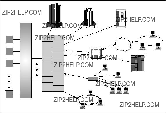
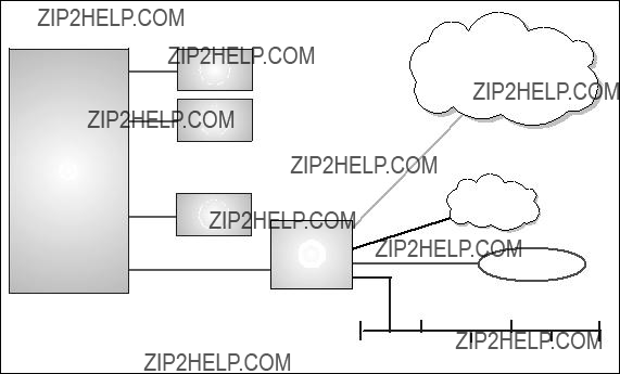
The distinguishing feature of the GRF, when compared with other routers, is that it has an SP Switch Router Adapter and therefore can connect directly to the SP Switch (see Figure 1 on page 6).
IBM 9570 Disk
Array
Subsystem
HIPPI
Adapter
Switch
SP Switch
Adapter
FDDI
SP Switch
SP System
Router
Figure 1. SP Switch Router
The RS/6000 SP software treats this adapter as an extension node. It is a node because it takes up one port in the SP Switch and is assigned a node number. It is described as an extension because it is not a standard RS/6000 SP node, but an adapter card that extends the scope of the RS/6000 SP.
Although the term extension node represents the node appearance of the adapter, it does not define the connection. An extension node adapter is used for that purpose. Each extension node has an extension node adapter to represent its connection to the SP Switch.
2.1.1 Motivation
A thin node, which has a single microchannel, is unable to deliver more than about 30 MB/s to or from the SP Switch. Using a wide node, this number increases to 65 MB/s but is still unable to provide full bandwidth to even one HIPPI interface. It is also unable to feed 4 FDDI or 4 Ethernet 100BaseTx cards at full bandwidth.
A 135 MHz wide node???s CPU becomes saturated at about 5000 packets/second. A 10 Mb/s Ethernet uses a maximum of 1500 bytes for a
6 IBM 9077 SP Switch Router: Get Connected to the SP Switch

packet size. This would only enable a wide node to handle approximately 7.5 MB/s of IP traffic.
Since Ascend???s business depends on keeping pace with networking technology, they already support the major interfaces today. The 9077 will be able to take advantage of any new interfaces that are developed in the future as well, with no further development time or money expended.
With some interfaces requiring up to 5 slots, even a wide node can run out of available slots. This forces additional nodes to be added even if there are no performance limitations in the current configuration.
Since there are no hot plug capabilities with an SP node, any failure means downtime on all interfaces configured in that node, and at times a lengthy maintenance procedure. Redundancy is not built into the SP node???s architecture.
These facts are illustrated in Figure 2:
Figure 2. Functional Comparison
Router Node 7
2.1.2 Design Objectives
Because the dependent node is part of the RS/6000 SP, it had to be packaged and assigned some roles consistent with other RS/6000 SP nodes. Changes were made to the RS/6000 SP to incorporate management requirements for the dependent node.
Ease of design and implementation were important objectives in the design. These were accomplished by limiting the amount of switchcontrol protocol for the dependent node.
New SDR (System Data Repository) classes were created to manage dependent nodes. This was done to minimize the scope of the changes and the exposure to side effects that dependent nodes may cause if they were represented as standard nodes in the SDR.
2.1.3 What is a Router
One of the basic functions of the Internet Protocol (IP) is its ability to connect between different networks. This is due its routing algorithm and its flexibility to use almost any physical network below. A system that connects different physical or logical networks and directs traffic is termed a router, although the older term IP gateway is also used.
Again, IP routing is the passing of an IP packet from one device to another by sending it on a physical or logical interface. routers interconnect networks so that IP traffic can be routed between the systems in the networks, as shown in Figure 3 on page 9.
8 IBM 9077 SP Switch Router: Get Connected to the SP Switch
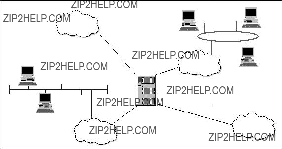
Figure 3. Typical Router Configuration
Routers help to reduce the amount of processing required on local systems, since they perform the computation of routes to remote systems. For example, a system can communicate with a remote system by passing the message (or packets) to the router. The router works out how to get to the remote system and forwards the message appropriately.
Storing routes on the system takes up memory. But because a system does not have to store routes to systems not in its own subnet, the route table uses less storage space and thereby frees up memory for other work.
The use of routing reduces network traffic, because routers encourage subnetting, which creates a smaller network of systems. By having smaller networks, network traffic congestion is reduced and overall network performance and traffic control are improved.
A network???s routing configuration does not always require a routing protocol. In situations where the routing information does not change, for example, when there is only one possible route, the system administrator usually builds the routing table manually. Some networks have no access to any other TCP/IP networks, and therefore do not require routing tables at all. The three most common routing configurations are:
Router Node 9
???Minimal routing
A network completely isolated from all other TCP/IP networks requires only minimal routing. A minimal routing table is usually built by ifconfig when the network interfaces are configured. If your network does not have direct access to other TCP/IP networks, and if you are not using subnetting, this may be the only routing table you require.
???Static routing
A network with a limited number of gateways to other TCP/IP networks can be configured with static routing. When a network has only one gateway, a static route is the best choice. A static routing table is constructed manually by the system administrator using the route command. See Figure 4. Static routing tables do not adjust to network changes, so they work best where routes do not change.
Figure 4.
???Dynamic routing
A network with more than one possible route to the same destination should use dynamic routing. A dynamic routing table is built from the information exchanged by the routing protocols. The protocols are designed to distribute information that dynamically adjusts routes to reflect changing network conditions. Routing protocols handle complex routing
10 IBM 9077 SP Switch Router: Get Connected to the SP Switch

situations more quickly and accurately than a system administrator can do. Routing protocols are designed not only to switch to a backup route when the primary route becomes inoperable; they are also designed to decide which is the "best" route to a destination. On any network where there are multiple paths to the same destination, a dynamic routing protocol should be used.
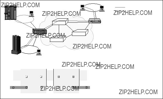
2.1.4 Routing without the GRF
Before the GRF was available, there were only two ways to get IP traffic from remote systems to reach the RS/6000 SP nodes:
1.By putting an additional IP adapter into every RS/6000 SP node.
2.By designating one or two nodes to act as a router (as shown in Figure 5).
Figure 5. Routing without GRF
The first option was usually not chosen because it was too costly for the following reasons:
???For systems with a large number of nodes having multiple IP adapters for each RS/6000 SP node can be expensive.
???The number of I/O slots in the RS/6000 SP node is limited. In addition, these slots are required to perform other tasks for the system, such as connecting to disk or tape. Using these I/O slots to connect IP adapters restricts the functions of the RS/6000 SP node.
Router Node 11
The second case has proven to be very expensive as well. The RS/6000 SP node was not designed for routing. It is not a
???It takes many CPU cycles to process routing. The CPU is not a dedicated router and is very inefficient when used to route IP traffic (this processing can result in usage of up to 90%).
???It takes a lot of memory to store route tables. The memory on the RS/6000 SP node is typically more expensive than router memory.
The CPU on a node can only drive the system I/O bus at less than 80 megabytes per second, which is less than what a
For these reasons, the performance of routers in handling IP traffic from remote systems to the RS/6000 SP nodes was limited.
2.1.5 Routing with the GRF
The GRF is a dedicated,
Figure 6. Routing with GRF
12 IBM 9077 SP Switch Router: Get Connected to the SP Switch
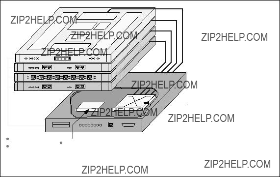
The GRF uses a crosspoint switch (see Figure 7) instead of an I/O bus to interconnect its adapters. This switch is capable of 4 or 16 Gbit/s (model dependent) and gives better performance than the MCA bus.
Figure 7. GRF 400
In conventional routers, each packet is processed at each gateway (also called hop) along a path. The processing is done at the Layer 3 level (see Figure 8 on page 14) and requires a router???s CPU to process both the packet and the route information. Conventional routers use shared resources, which leads to congestion and poor scalability and performance.
Router Node 13
Router
Unswitched Data
Switched Data
Disadvantages:
 Shared data paths
 All processing done on Layer 3
 Slow softwarebased processing
Layer 3
Layer 2
Figure 8. Conventional Routers
The SP Switch Router provides near
14 IBM 9077 SP Switch Router: Get Connected to the SP Switch
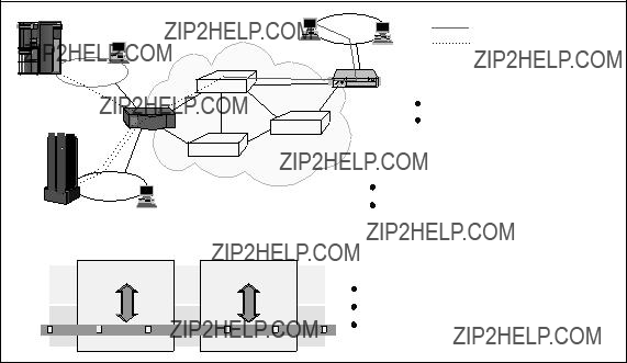
Figure 9. Switched Routers
Other advantages of using GRF are as follows:
???Availability of a redundant power supply
???Availability of a redundant fan
???Availability of a
???Availability of a
???Availability of
???Scalability of up to 4 or 16 media adapters, depending on the GRF model
Perhaps the greatest advantage of using the GRF is improved price/performance. As previously mentioned, the GRF is a dedicated router, and as such it is much more cost effective for routing IP traffic than using dedicated RS/6000 SP node.
2.1.6 Overview of Supported Routing Protocols
In addition to static routes, various routing protocols are available on the GRF, as follows:
RIPRouting Information Protocol Version 1 or 2 (RIP 1 or 2)
OSPFOpen Shortest Path First
Router Node 15
MulticastIP Multicast and OSPF Multicast
EGPExterior Gateway Protocol
BGPBorder Gateway Protocol Version 3 or 4 (BGP 3 or 4)
More details about the various protocols are in Section 2.2.2, ???Supported Routing Protocols??? on page 20.
2.1.7 Media Adapters
Available IP forwarding media cards are:
???
???
???
???
???
???
???
???
More details are in Section 2.3.8, ???Other Media Cards??? on page 39.
2.1.8 Benefits of the GRF
The crosspoint switch is a nonblocking crossbar. This architecture is faster than an RS/6000 SP node, in which media adapters communicate through a shared microchannel bus.
To take advantage of the fast I/O provided by the crosspoint switch, fast route table access time is required. The GRF can store up to 150,000 routes in memory on each media card, while an RS/6000 SP node can store only hundreds. It is said that you need about 50,000 routes for the whole Internet. This means that the GRF is able to retrieve a route faster than an RS/6000 SP node.
The GRF is able to route up to 2.8 million packets per second for the
All the media adapters on the GRF are
16 IBM 9077 SP Switch Router: Get Connected to the SP Switch

adapter. As a result, other network adapters are brought down as well. Bringing down the router will impact all the networks in the location.
Each RS/6000 SP is allowed to connect to multiple SP Switch Router Adapters, and it does not matter if these adapters are on different GRFs. Connecting multiple SP Switch Router adapters to either different partitions in an RS/6000 SP or to different RS/6000 SPs allows them to communicate with each other and with the other GRF media adapters via the SP Switch.
Attention
The SP Switch Router model 04S can support four media cards such as FDDI or ATM. The SP Switch Router model 16S can support 16. All card slots could be occupied by SP Switch Router adapters; this means a maximum of 4 SP Switch Router adapters for model 04S and a maximum of 16 SP Switch Router adapters for model 16S.
Note: The number of packets that the GRF can route per second depends on the following:
???The type of media adapter
???The size of the packet
2.1.9 Price Comparison
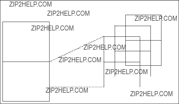
Figure 10 on page 18 shows a price comparison between an RS/6000 SP node solution and a GRF based solution for three sample configurations.
Router Node 17

Figure 10. Price Comparison
These price comparisons are based on US prices as of March 1998. In other countries these prices may be different. The basic message of these charts is that the solutions based on the GRF could be quite competitive and will quite often be cheaper than the conventional configurations.
Let us look, for example for a solution connecting an RS/6000 SP via HIPPI to a mainframe system. The first chart shows that a GRF solution is cheaper than adding a dedicated node for the HIPPI connection to your system, apart from the fact that the GRF solution is the better choice from a performance point of view.
It is nearly the same if you need a connection to an FDDI network. One GRF FDDI media card offers four independent singlering connections. An offer based on an dedicated SP node is more expensive than a GRF solution.
Our example on the third chart focuses on an ATM connection. In this case, the RS/6000 SP node based solution is the more reasonable solution, if you consider only the price. But the difference is not that much; the growth path with the
2.2 GRF Software
The software functionality of the GRF is distributed between the Router Manager on the IP Switch Control Board (see also Section 2.3.2, ???GRF Features??? on page 26) and the individual media cards. While the Route
18 IBM 9077 SP Switch Router: Get Connected to the SP Switch
Manager updates the system routing tables and performs other administrative functions, the intelligent processors on each media card perform all routing functions. This design supports efficient distributed processing of router operations.
2.2.1 IP Protocol
The GRF supports IP datagram routing between major types of standard media. The implementation conforms with IP Version 4 and routing specifications described in Internet RFCs.
Each media card has a complete set of route and Address Resolution Protocol (ARP) information contained in the program memory space of the card???s
Data Forwarding
Individual media cards maintain their own route tables, perform lookups, and autonomously handle the passing of datagrams to other media cards for export, without intervention of the Router Manager.
Route Table Implementation
Critical to providing sustained performance in a highly dynamic environment are the cacheless route table and route lookup implementation. Each card carries a complete copy of the route table and can support up to 150,000 entries.
Keeping pace with significant advances in routing, the GRF also supports
Router Node 19
Subnet Masking/Supernetting
Variable length subnet masking is a classless addressing scheme for interdomain IP packet routing. It is a way to more efficiently manage the current
Subnet masking offers a number of benefits by extending the current address space. By eliminating implicit netmask assignments, addresses can now be assigned from any unused portion of the entire
Classless addressing allows the network administrator to further apportion an assigned address block into smaller network (or host) segments based on powers of two (2, 4, 8, 16 networks, for example). Knowledge of the apportioned segments need not be communicated to exterior peers. They need only a single pointer to the entire address block. Not only does subnet masking better utilize address space, but implemented properly it results in significantly smaller routing tables.
2.2.2 Supported Routing Protocols
In the days of a single Internet, core groups of independent networks were called autonomous systems. We will use the term autonomous systems (AS) in the following description of protocols. The routing protocols supported on the GRF can be divided into two classes: Interior routing protocols or interior gateway protocols (IGPs) and Exterior routing protocols (EGPs).
???Interior routing protocols
Interior routing protocols are used to exchange routing information between routers within a single autonomous system. They are also used by routers that run exterior protocols to collect network reachability
20 IBM 9077 SP Switch Router: Get Connected to the SP Switch
information for the autonomous system. Here is the list of interior protocols supported by the GRF:
???RIP
The Routing Information Protocol (RIP), as delivered with most UNIX systems, is run by the routing deamon routed. During the startup of routed a request for routing updates is issued. After that, the daemon listens for responses to the request. Systems that are configured to supply RIP information hear this request and respond with update packets based on the information in the system???s routing table. The update packets contain the destination addresses from the routing table and the routing metrics associated with each destination. Update packets are send on request and periodically to keep routing information accurate.
???OSPF
Open Shortest Path First (OSPF) is defined by RFC 2178 (Request for Comments). It is a
???Areas
These are sets of networks within a single autonomous system that have been grouped together. The topology of an area is hidden from the rest of the autonomous system, and each area has a separate topology database. Routing within the autonomous system takes place on two levels, depending on whether the source and destination of a packet reside in the same area
The dividing of an autonomous system into areas enables a significant reduction in the volume of routing traffic required to manage the routing database for a large autonomous system.
???Backbone
The backbone consists of those networks not contained in any area, their attached routers, and routers that belong to multiple areas.
Router Node 21
Every area must connect to the backbone, because the backbone is responsible for the distribution of routing information between areas. The backbone itself has all the properties of an area. Its topology is separate from that of other areas.
???Subarea
A subarea has only one area border router, which means that there is only one route out of the area. In this case, the area border router does not need to advertise external routes to the other routers within the subarea. It can simply advertise itself as the default route.
???The sequence of operations performed by OSPF routers is as follows:
1.Discovering OSPF neighbors
2.Electing the Designated Router
3.Forming adjacencies
4.Synchronizing databases
5.Calculating the routing table
6.Advertising Link States
Routers go through these steps when they first come up, and repeat them in response to the events that occur in the network. Each router must perform each of these steps for each network it is connected to, except for the calculation of the routing table. Each router generates and maintains a single routing table for all networks.
???Multicast
???IP Multicast
The GRF supports IP multicast routing per RFC 1112 and some components of RFCs 1301 and 1469. The implementation includes the IP multicast kernel modifications, dynamic route support and mrouted (multicast route daemon).
Data that arrives at a GRF interface is duplicated and forwarded to multiple destination interfaces. The multicast packet???s destination address is a Class D address. A lookup of the multicast route table returns a list of Virtual Interfaces (VIFs) to which the packet is sent.
???OSPF Multicast
The GRF uses the multicast capability of OSPF Version 2, as described in RFC 1583 and RIP Version 2, for communications between routers.
22 IBM 9077 SP Switch Router: Get Connected to the SP Switch
Host extensions for IP multicasting as described in RFC 1112 are also provided. The Router Manager acts as a host and uses the
Internet Group Management Protocol (IGMP), version 2, to add and delete its membership in multicast groups. Accordingly, the Route Manager "joins" the appropriate routing protocol host groups for OSPF and RIP.
???
Intermediate System to Intermediate System (an OSI gateway protocol) is a protocol similar to OSPF: it also uses a Link State, Shortest Path First algorithm. However,
???Exterior Routing Protocols
Exterior Routing Protocols are used to exchange routing information between routers in different autonomous systems. Here is the list of exterior routing protocols supported by the GRF:
???EGP
The Exterior Gateway Protocol (EGP) is the protocol used for exchange of routing information between exterior gateways (not belonging to the same autonomous system).
EGP gateways may only forward reachability information for networks within their autonomous system. This routing information must be collected by the EGP gateway, usually via an GP).
???BGP
Border Gateway Protocol (BGP) is the leading exterior routing protocol of the Internet and is replacing EGP as the exterior protocol of choice. It is based on the OSI InterDomain Routing Protocol (IDRP). BGP supports
2.2.3 Filtering
IP filtering supports specific permit or deny decisions for each instance of a filter (per logical interface). The criteria within each filter may include any combination of the following:
??? Protocol (ICMP, TCP, UDP)
Router Node 23

???Source address
???Destination address
???Protocol port number (single number, or range, or ranges) for TCP and
UDP
???Established TCP connections
2.2.4 System Management
The GRF currently supports the Simple Network Management Protocol
(SNMP) Version 1, which provides a mechanism for remote query or setting operational parameters for the device. Media cards collect network statistics, which can be reported to network management packages via the Router Manager on the IP Switch Control Board. In addition to collection statistics and other management information, the SNMP agent is also capable of issuing traps. For more information, see Section 2.4.5, ???SP Extension Node SNMP Manager??? on page 58.
2.3 GRF Hardware
As already mentioned, the unique GRF switching architecture is specially designed for
2.3.1 GRF Block Diagram
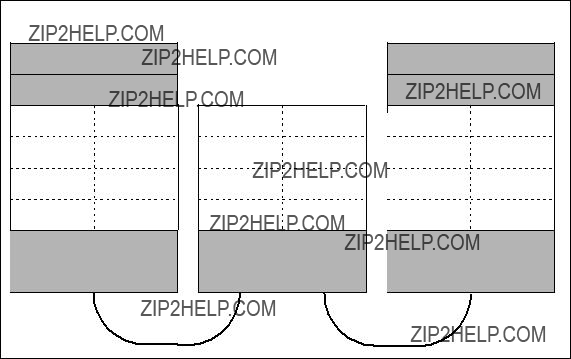
Figure 11 on page 25 shows the two models: the
24 IBM 9077 SP Switch Router: Get Connected to the SP Switch
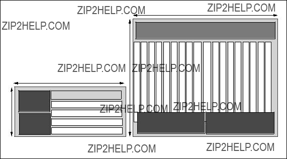
Figure 11. GRF Models
The SP Switch Router model 9077 04S (GRF 400) can accommodate up to four media adapters.
The SP Switch Router model 9077 16S (GRF 1600) can accommodate up to 16 media adapters.
Each adapter enables the GRF to connect to one or more networks.
Each of the models has an additional slot for the IP Switch Control Board, which is used to control the router.
GRF 400
PartDescription
Cooling FansThese are located on the right side of the chassis and cannot be accessed without bringing down the GRF. The fans are redundant, allowing service to be deferred until it is convenient to bring down the GRF.
Media CardsThere are four media card slots on this chassis. They are slotted horizontally and are located at the bottom of the chassis.
IP Switch Control BoardThis board is located at the top of the four media slots and is also slotted horizontally.
Router Node 25
Power SupplyThe left side of the chassis is reserved for the two power supplies that are required for redundancy.
The failed power supply can be
GRF 1600
Part Description
Cooling FansThese are located at the top of the chassis, and can be accessed separately from the other parts of the GRF. The fan tray contains redundant fans and is
Media CardsThere are 16 media card slots on this chassis. They are slotted vertically. Eight of the cards are on the left side of the chassis, and eight are on the right side.
IP Switch and
Control BoardThese boards are located in the middle of the 16 media slots and are also slotted vertically.
Power SupplyThe base of the chassis is reserved for the two power supplies that are required for redundancy. The failed power supply can be
2.3.2 GRF Features
GRF has the following features:
???Redundant power supply
Should any power supply fail, a message is sent to the control board. The power supply will automatically reduce its output voltage if the temperature exceeds 90 ??C (194 ??F). If the voltage falls below 180V, the GRF automatically shuts down.
???
The faulty power supply can be replaced while the GRF is in operation.
???Redundant fan
For the GRF 1600 model, if one fan breaks down, a message is sent to the control board.
For both models, when the temperature reaches 53??C (128 ??F), an audible alarm sounds continuously, and a message is sent to the console and logged into the message log.
26 IBM 9077 SP Switch Router: Get Connected to the SP Switch
If the temperature exceeds 57.5 ??C (137 ??F), the GRF does an automatic system shutdown.
???
For the GRF 16S model, the cooling fan can be replaced while the GRF is in operation.
???
There are two types of adapters on the GRF: the media adapters and the IP Switch Control Board.
The media adapters are independent of each other and can be replaced or removed without affecting any other adapter or the operation of the GRF.
However, the IP Switch Control Board is critical to the GRF. Should this board be unavailable, the router fails.
???Crosspoint switch
The crosspoint switch is a 16x16 (16Gb per second) or 4x4 (4Gb per second) crossbar switch for the GRF 16S and GRF 04S, respectively, see Figure 12 on page 27. It is the I/O path used when the media adapters need to communicate with each other.
Serial Interface
CPU 
............
..........
Combus
 Dynamic Routing Engine (Route Manager)
 Configuration/Control
 16MB Rx / 16MB Tx Buffers
 Speed decoupling

 WAN delays
 QBRT Route Table Lookup

 Times range from


 IP Header
 Route decisions
4 Gb/s Switch
1.Normally, all media cards have a 4 MB send buffer and a 4 MB receive buffer, except the SP Switch Adapter card, which has a 16 MB buffer size for each buffer. See also Section 2.3.5, ???Characteristics of GRF Media Cards??? on page 36 and Figure 19 on page 37.
2.Quick Branch Routing Technology (QBRT) is a
The benefit of this architecture is that the entire route table can be stored locally on the media card and searched quickly. In the traditional cached route table method, a small number of routes can be stored and searched locally. However, when a large number of routes is desired, or the kind of traffic one would see on the Internet backbone arises, caching is inadequate. Inevitably, cache misses occur, and route table lookups are performed at a limited, central, shared resource.
Performance is enhanced even further with parallel processing of table lookups occurring on each media card, which is another technique that helps assure linear scalability. The router manager on the controller board, which also contains the switch fabric, maintains the master route table and distributes updates simultaneously to all installed media cards, even as the cards continue their forwarding functions.
3.
4.Router management takes place on the IP Switch Control Board (see Section 2.3.3.2, ???IP Switch Control Board Components??? on page 33), based on a 166 Mhz Pentium processor. It is responsible for system monitoring, configuration management and the user interface.
5.The GRF communications bus (Combus) is an
2.3.2.1 Data Packet Processing
With the knowledge about the local routing functions of the media cards, we now look at Figure 13 on page 29 to see how a data packet is transferred from one media card to another.
28 IBM 9077 SP Switch Router: Get Connected to the SP Switch

Figure 13. Data Packet Transfer
The routing can be divided into the following steps:
1.A data packet is received by the media card.
2.The packet is transferred to the receive buffer by the DMA engine.
3.The CPU examines the header and gives the destination address to the route lookup hardware.
4.The QBRT finds the next hop in the route table.
5.A special header is added to the packet by the CPU. This header contains information for the downstream card to process the packet, as well as the next hop found by the QBRT.
6.The packet is then transferred to the internal serial interface by the DMA engine.
7.A connection to the downstream card is set up through the switch.
8.The serial stream is converted back to parallel format by the downstream card.
9.The packet is transferred to the transmit buffer by the DMA engine.
Router Node 29

10.The header is examined by the CPU, which uses the information to build a new header that will deliver the data across the media interface.
11.The DMA engine transfers the packet to the media interface.
12.The packet is transferred across the media.
2.3.2.2 Routing Packet Processing
The processing of packets with routing information is a little bit different from the data packet processing procedure as you can see in Figure 14.
Figure 14. Routing Packet Processing
These are the steps for processing routing packets:
1.A routing packet is received by the media card.
2.The packet is transferred to the receive buffer by the DMA engine.
3.The CPU examines the header and gives the destination address to the route lookup hardware.
4.The QBRT finds the next hop in the route table.
5.A special header is added to the packet by the CPU. This header contains information for the downstream card. The result of the hardware lookup determines whether the packet should be forwarded to the Router Manager.
30 IBM 9077 SP Switch Router: Get Connected to the SP Switch
6.The packet is then transferred to the Combus interface by the DMA engine.
7.The packet is sent to the IP Switch Control Board???s Router Manager across the Combus.
8.The Route Manager receives the packet and passes it to the dynamic routing software.
9.The packet is processed and global routing information is determined. 10.Route updates are broadcast across the Combus to all media cards
simultaneously.
11.Each card receives the update packet and makes changes to its route tables.
12.The packet is transferred across the media.
To ensure that dynamic routing packets are not dropped during times of heavy congestion, precedence features are used. Routing packets are given a
2.3.3 IP Switch and Control Board
The control board, also known as the IP Switch Control Board, is accessed through Telnet or a locally attached VT100 terminal. The IP Switch Control Board is supplied with the GRF and is necessary for its operation. The VT100 terminal is not supplied with the GRF. It is only needed for the installation of the GRF.
Using terminal emulation software instead of looking for a real VT 100 terminal may be an alternative. You can use your Control Workstation or one of your SP nodes. Install the ATE package (advanced terminal emulation) on your RS/6000 and establish a serial connection between the system and the router.
After installation, all future access to the GRF can be through Telnet to the IP Switch Control Board???s administrative Ethernet.
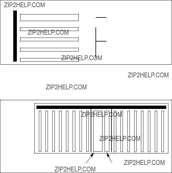
The IP Switch Control Board is identified as slot 66 in both GRF models. A sideview of the GRF 400 slot numbering scheme is shown in Figure 15 on page 32.
Router Node 31
Backplane
66
3
2
1
0
IP Switch Control Board
Slot numbers in decimal for media cards
Figure 15. Side View of GRF 400 Chassis with Slots Numbered
The GRF 1600 has 16 media slots. The control board is located in slot 66, as shown in Figure 16.
Figure 16. Top View of the GRF 1600 Chassis
The CPU in the IP Switch Control Board is a 166MHz Pentium processor and runs a variant of BSD UNIX as its operating system. For this reason, the GRF administrator is assumed to be proficient in UNIX.
The IP Switch Control Board is used to install, boot, and configure the router and its media adapters.
It is also used for the logging of messages, the dumping of memory and status, and to perform diagnostic checking of both the GRF and the media adapters.
32 IBM 9077 SP Switch Router: Get Connected to the SP Switch
2.3.3.1 Route Manager
As already mentioned, the router management takes place on the IP Switch Control Board.
Specific functions of the Route Manager are:
???It processes all dynamic routing packets.
???It synchronizes the route tables on the media cards.
???It controls the media cards: issues interrupts and resets to individual media cards and downloads executable programs and connection information.
2.3.3.2 IP Switch Control Board Components
Let us examine the IP Switch Control Board in more detail.
Figure 17 shows all the components of the IP Switch Control Board:
Router Node 33
ItemDescription
MemoryThe IP Switch Control Board comes standard with 128 MB of memory (the four shaded blocks of 32 MB of memory in the upper left corner).
The memory can be upgraded to 256 MB, in increments of 64 MB (the four white blocks of memory).
The system uses the first 32 MB of memory for file system storage. The top half is used for applications such as the SNMP agent, the gated daemon, and for the operating system.
Flash memoryThis memory (the 85 MB ATA flash memory on the system) is used to store the operating system information and the configuration information for the GRF.
System busThis bus is used by the IP Switch Control Board components to communicate with each other.
Pentium processorThis 166 MHz processor drives the IP Switch Control Board and the GRF. As previously mentioned, this processor runs a variant of BSD UNIX, and so it is useful for the GRF administrator to have UNIX management skills.
Administrative EthernetThis Ethernet is known to the GRF as de0. This port supports the 10BaseT or the 100BaseT Ethernets and switches between them automatically, depending on the type of network used.
To use 10Base2 or 10Base5, the user must add a transceiver (supplied by the user).
PCMCIA cardsThe two white blocks at the bottom right corner of the figure are PCMCIA slots.
There are two types of PCMCIA cards:
??? Slot A on the 9077 is configured with a 520 MB disk drive. This disk is used to hold the log of the GRF. It may also be used to backup the configuration of the GRF. Making a backup is strongly recommended.
??? The PCMCIA modem card, also available as an optional device, allows the user to dial into the GRF through a modem to administer it remotely.
Note: For the initial setup, the console must be available locally, not through the modem.
34 IBM 9077 SP Switch Router: Get Connected to the SP Switch
Additionally, the RS232 port (which is not shown in the figure) allows you to connect the VT100 console by using an RS232 null modem cable. The console and cable must be supplied by the user.
2.3.4 Memory Guidelines for the IP Switch Control Board
As already mentioned, the GRF base system comes with 128 MB of memory. In all GRF memory configurations, 32 MB are used for the file system and the remainder is used for system operations. For example, in the base system, there are 128 MB of total memory, 32 MB of available memory and 78 MB of usable memory. (Refer to Table 1 on page 35 for detailed memory configuration information). Up to six additional 32 MB DRAM SIMMS may be added to support larger dynamic routing tables and larger numbers of peers (for a total of 256 MB, 204 MB usable).
The following table provides guidelines for memory configuration. All media cards can hold up to 150 KB route entries. The control board, depending on memory configuration, can hold 35,805 to 521,730 route prefixes. Select the amount of memory according to your routing environment. Additional memory may be required for higher average numbers of routes per BGP peer.
Figure 18 gives an overview of the memory layout and the possible memory extensions.
Router Node 35
64MB RAM
64MB RAM
64MB RAM
- System software
32MB (fixed size)
64MB RAM
- Config files
- Gated binary
Figure 18. System RAM
2.3.5 Characteristics of GRF Media Cards
All GRF media cards (media adapters) are
Each media card has an onboard processor that is responsible for IP forwarding on the media adapter.
Each media card has two independent memory buffers, a 4 MB send buffer and a 4 MB receive buffer. These buffers are necessary to balance the speed differences between the media adapters, because they have different transfer rates.
Each onboard processor has local memory that can contain a local route table with up to 150,000 entries, to be used for routing on the media adapter. Because these route entries are in local memory, access to them is very fast. When the media adapter is started up, it gets its initial route entries from the IP Switch Control Board.
2.3.6 SP Switch Router Adapter
The GRF supports a number of media adapters. Figure 19 describes the SP Switch Router Adapter in detail. This adapter allows the GRF to connect directly into the SP Switch.
36 IBM 9077 SP Switch Router: Get Connected to the SP Switch

Figure 19. SP Switch Router Adapter
The SP Switch Router Adapter is made up of two parts: the media board and a serial daughter card.
The serial daughter card is an interface for the media board into the crosspoint switch. This switch is the medium by which the GRF (media) adapters talk to each other.
The purpose of the media board is to route IP packets to their intended destination through the GRF. The SP Switch Router adapter described here is used for routing IP packets to and from the SP Switch to other systems connected directly or indirectly to the GRF. A brief description of the components on the media board follows.
Receive TBICThis component receives data segments from the SP Switch and notifies the Receive Controller and Processor that there is data to be transferred to the buffer.
Router Node 37
Receive Controller
and ProcessorThis component recognizes the SP Switch segments and assembles them into IP packets in the 16 MB buffer. Up to 256 IP datagrams can be handled simultaneously. When a complete IP packet has been received, the Receive Controller sends the packet to the FIFO (1) queue for transfer to the serial daughter card.
Buffer (1)This component is segmented into 256 64 KB IP packet buffers. It is used to reassemble IP packets before sending them to the FIFO queue, as switch data segments may arrive out of order and interleaved with segments belonging to different IP packets.
FIFO (1)This component is used to transfer complete IP packets to the serial daughter card and even the flow of data between the SP and GRF crosspoint switch.
FIFO (2)This component receives IP packets from the serial daughter card and transfers them to Buffer (2).
Buffer (2)This buffer is used to temporarily store the IP packet while its IP address is examined and a proper SP Switch route is set up to transfer the packet through the SP Switch.
Send Controller
and ProcessorThis component is notified when an IP packet is received in the FIFO (2) queue and sets up a DMA transfer to send the packet to Buffer (2). The Send Processor looks up the IP address in the packet header and determines the SP Switch route for the packet, before notifying the Send Controller to send the packet to the Send TBIC from Buffer (2).
Send TBICThis component receives data from Buffer (2) and sends it in SP Switch data segments to the SP Switch.
2.3.7 Media Card Performance
The SP Switch Router adapter has the following performance characteristics:
???It is able to transfer up to 100 MB per second. The limiting factor is the crosspoint switch connection bandwidth.
38 IBM 9077 SP Switch Router: Get Connected to the SP Switch
???It is able to transfer up to 30,000 packets per second. At 20,000 packets per second, each packet needs to be at 5 KB in order to achieve the 100 MB per second transfer rate mentioned.
???As previously mentioned, each adapter stores its own route tables in memory. Therefore, route table lookup is very fast, that is, less than 2.5 ??s.
???Finally, each media adapter has a 1 Gbit per second dedicated link into the crosspoint switch. That is why the
2.3.8 Other Media Cards
The following are other media cards and adapters currently supported on the GRF:
EthernetThe 10/100 Mb Ethernet media adapter consists of eight 10/100BaseT Ethernet ports. All ports support only shielded twisted pair (STP) and unshielded twisted pair
ATM
ATM
FDDIThe FDDI media card provides four ports in the card. These ports allow the media card to be connected into the Fiber Distributed Data Interchange (FDDI). The four ports can be configured such that they support the following:
???Two
???One
???Four
HIPPIThe HIPPI media adapter is a
HSSIThe High Speed Serial Interface (HSSI) is a
Router Node 39

IP/SONETThe IP/SONET
2.3.9 GRF Operating Environment
As previously mentioned, the operating temperature should not exceed 53 ??C (128 ??F). Even though there is a buffer between the operating temperature and the warning temperature, it is best to keep the temperature within the operating level in order to minimize the possibility of damage to GRF components.
2.4 PSSP Enhancements
This section discusses the enhancements made to PSSP to accommodate the Dependent Node Architecture.
2.4.1 SDR Enhancements
As mentioned in Section 2.1.2, ???Design Objectives??? on page 8, the System Data Repository (SDR) needed to be extended to support the dependent node architecture. Two classes have been added to the SDR.
???DependentNode
???DependentAdapter
2.4.1.1 DependentNode Attributes
The attributes of the DependentNode class are described in Table 2:
Table 2. DependentNode Attributes
40 IBM 9077 SP Switch Router: Get Connected to the SP Switch
The attributes of the DependentNode class are described in detail as follows:
AttributeDescription
node_numberThis
extension_node_identifierThis is a
reliable_hostnameThe hostname of the administrative Ethernet, de0, is the GRF???s hostname. Use the long version of the hostname when DNS is used.
management_agent_hostnameThis attribute is the hostname of the SNMP agent for the GRF. For the GRF dependent node, this is the same as the reliable_hostname.
snmp_community_nameThis field contains the SNMP community name that the SP Extension Node SNMP Manager and the GRF???s SNMP Agent will send in the corresponding field of the SNMP messages. This value must match the value specified in the /etc/snmpd.conf file. If left blank, a default name found in the SP Switch Router Adapter documentation is used.
The following attributes are derived by the RS/6000 SP system when the SDR_config routine of endefnode is invoked.
AttributeDescription
switch_node_numberThe switch port that the dependent node is attached to.
switch_numberThe switch board that the dependent node is attached to. switch_chipThe switch chip that the dependent node is attached to.
switch_chip_portThe switch chip port that the dependent node is attached to.
switch_partition_numberThe partition number to which the dependent node belongs.
Router Node 41
2.4.1.2 DependentAdapter Attributes
The attributes of the DependentAdapter class are described in Table 3:
Table 3. DependentAdapter Attributes
The attributes of the DependentAdapter class are described in detail as follows:
AttributeDescription
node_numberThis
netaddrThis is the IP address of the SP Switch Router adapter. netmaskThis is the netmask of the SP Switch Router adapter.
2.4.1.3 Additional Attributes
As Table 4 shows, additional attributes are added to the Syspar_map_class and the Switch_partition classes:
Table 4. Additional SDR Attributes
Details of these attributes follow:
42 IBM 9077 SP Switch Router: Get Connected to the SP Switch
AttributeDescription
node_typeThis attribute is set to dependent for GRF and to standard for all other RS/6000 SP nodes.
switch_max_ltuThis specifies the maximum packet length of data on the SP Switch; the default is 1024. Do not change this value for any reason.
switch_link_delaySpecifies the delay for a message to be sent between the two furthest points on the switch; the default is 31. Do not change this value for any reason.
2.4.2 New Commands
To support the dependent node architecture, seven new commands were added. These commands can be divided into two groups. The first group must only be executed with root permission on the Control Workstation. The second group can be executed by any user on any standard RS/6000 SP node.
Table 5 shows a list of commands of the first group:
Table 5. New Commands (root Executable)
The first four commands all have the same characteristics, which are as follows:
???The are part of the ssp.basic fileset.
???They must only be executed on the Control Workstation.
???They can only be executed by the root user.
???They only affect the current active partition.
???They only affect the SDR, unless the
???They return a code of 0 if successful, 1 if failed.
Router Node 43
The enadmin command is used to change the administrative state of a dependent node in the GRF; it has the following characteristics:
???It is part of the ssp.spmgr fileset.
???It must only be executed on the Control Workstation.
???It can only be executed by the root user.
???The
reconfigure, while the
??? The return code is 0 if successful, 1 if failed.
Table 6 shows the list of commands from the second group (executable by any user on any standard node):
Table 6. New Commands (User Executable)
These commands have the following characteristics:
???They are part of the ssp.basic fileset.
???They can be executed on any standard RS/6000 SP node.
???They can be executed by any user.
???They only affect the current active partition unless the
The following sections describe the commands in more detail.
2.4.2.1 The endefnode Command
The endefnode command can be executed using smit. The fast path for smit is enter_extnode. This command is used to add or change an extension node in the SDR DependentNode class. Its options are shown in Table 7 on page 45.
44 IBM 9077 SP Switch Router: Get Connected to the SP Switch
Table 7. endefnode Command Options
This command adds attribute information for the extension node. The endefadapter command adds IP information, such as the IP address and netmask for the extension node. Together, these two commands define the extension node.
Router Node 45

Attention
Note that this command only affects the SDR, unless the
When the GRF is properly configured and powered on, with the SP Switch Router Adapter inside, it periodically polls the Control Workstation for configuration data. The
2.4.2.2 The enrmnode Command
The enrmnode command is used to remove an extension node from the SDR DependentNode class and can also be executed using smit. The fast path for smit is delete_extnode. Its options are shown in Table 8.
Table 8. enrmnode Command Options
Attention
Note that this command only affects the SDR, unless the
46 IBM 9077 SP Switch Router: Get Connected to the SP Switch

2.4.2.3 The endefadapter Command
The endefadapter command is used to add or change the extension node adapter IP information in the SDR DependentAdapter object, and can be executed using smit. The fast path for smit is enter_extadapter. The command options are shown in Table 9.
Table 9. endefadapter Command Options
Attention
Note that this command only affects the SDR, unless the
When the GRF is properly configured and powered on, with the SP Switch Router Adapter inside, it periodically polls the Control Workstation for configuration data. The
2.4.2.4 The enrmadapter Command
The enrmadapter command is used to remove the SDR DependentAdapter object, and can also be executed using smit. The fast path for smit is delete_extadapter.
Router Node 47
2.4.2.5 The enadmin Command
The enadmin command is used to change the status of the SP Switch router adapter in the GRF and can also be executed using smit. The fast path for smit is manage_extnode. The command options are shown in Table 10.
Table 10. enadmin Command Options
48 IBM 9077 SP Switch Router: Get Connected to the SP Switch
2.4.2.6 The splstnodes Command
The splstnodes command is used to list the node attributes of all nodes in the SDR, and can also be executed using smit. The fast path for smit is list_extnode. See all command options in Table 11.
Table 11. splstnode Command Options
Router Node 49
2.4.2.7 The splstadapters Command
The splstadapers command is used to list the adapter attributes of all nodes in the SDR, and can also be executed using smit. The fast path for smit is list_extadapter. See all command options in Table 12.
Table 12. splstadapter Command Options
50 IBM 9077 SP Switch Router: Get Connected to the SP Switch
2.4.3 Enhanced Commands
The following commands (see Table 13) have been modified due to the introduction of the dependent node:
Table 13. Enhanced Commands
Here is a more detailed description about the modifications:
???Eprimary
This command has been modified so that dependent nodes will not be able to act as a Primary or Primary Backup node for the SP Switch in the partition. The dependent node does not run the RS/6000 SP Switch codes like standard RS/6000 SP nodes and therefore does not have the ability to act as the Primary or Primary Backup node.
???Estart
This command functions as it does with normal nodes. It was enhanced to support the depend node in the RS/6000 SP.
???Efence
This command functions as it does with normal nodes in the RS/6000 SP. In addition, the dependent node can be fenced from the SP Switch with autojoin like any other standard RS/6000 SP node.
???Eunfence
This command functions as it does with normal nodes in the RS/6000 SP. In addition, the dependent node can rejoin the SP Switch network with this command, if that node was previously removed from the switch network due to failures or Efence.
Router Node 51
2.4.4 Hardware Perspectives
In Perspectives IP Node is used as a convenient and short descriptive term easily displayed in the GUI. It conveys the role and functions of the dependent node. Currently, this is the only dependent node.
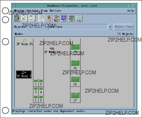
In Figure 20 we show the changes made to Perspectives because of the introduction of the IP Node. The changes are restricted to the Hardware and System Partition Aid Perspectives.
1
2
3
4
Figure 20. Hardware Perspectives
This figure shows the Hardware Perspectives, which can be started using the command perspectives and selecting the Hardware icon. Alternatively, it can be started directly via the command sphardware.
The Hardware Perspective consists of the following four parts:
1.Menu bar
2.Toolbar
52 IBM 9077 SP Switch Router: Get Connected to the SP Switch
3.Nodes pane (Frame or Icon View)
4.Information area
The most obvious change is the addition of the IP Node icon as seen in the Nodes pane. (The figure above shows the Frame View.) The default label for this icon is IP Node <node number>.
The IP Node icon is also located on the side of the frame, where a standard node with that node number would be. In this figure the IP Nodes are 7, 14 and 15.
When switch_responds is monitored, it shows the IP Node in two states:
???Green when working with the SP Switch.
???Marked with a red cross when fenced or not operating due to hardware or configuration problems.
In the figure, IP Node 7 and 15 are working, while IP Node 14 is down.
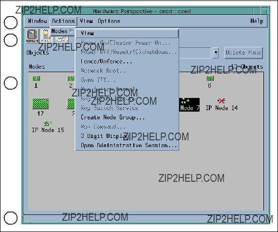
2.4.4.1 Action Menu
In Figure 21 on page 54, we see that IP Node 7 is selected in the Nodes pane, and
Router Node 53
1
2
3
4
Figure 21. Action Menu
???View
This will bring up the IP Node???s hardware notebook, shown in the next figure.
???Fence/Unfence...
This will bring up another window to allow us to either fence or unfence an IP Node. If we are fencing the IP Node, we can use the option of autojoin.
???Create Node Group...
This will bring up another window to allow us to add the RS/6000 SP nodes to a Node Group. This action does not affect the IP Node, even though it is selectable.
???3 Digit Display
54 IBM 9077 SP Switch Router: Get Connected to the SP Switch
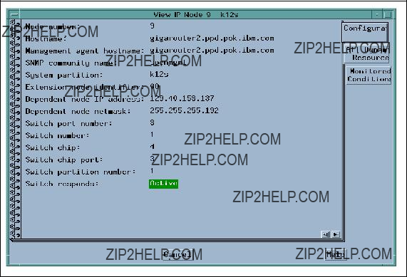
This will bring up a window to show the
???Open Administrative Session...
This action will open a window that is a Telnet session to the GRF, using the reliable_hostname attribute specified in the DependentNode class.
In addition, the Nodes pane in this figure shows the Icon View. In this view, the IP Node icons are always located after all the standard RS/6000 SP node icons. The results of monitoring the IP Nodes and the icon labels are the same as those of Frame View, mentioned in the previous figure.
2.4.4.2 Hardware Notebook
Figure 22 shows the IP Node hardware notebook. This notebook can be triggered by selecting the Notebook icon on the Hardware Perspective toolbar (2), or selecting
Figure 22. Hardware Notebook
The notebook has three tabs: Configuration, All Dynamic Resource Variables, and Monitored Conditions. This figure shows the Configuration tab.
Router Node 55
These are the attributes listed in the Configuration tab:
???Node number
???Hostname
???Management agent hostname
???SNMP community name
???System partition
???Extension node identifier
???Dependent node IP address
???Dependent node netmask
???Switch port number
???Switch number
???Switch chip
???Switch chip port
???Switch partition number
???Switch responds
The All Dynamic Resource Variables tab only shows the state of the Switch Responds, and the Monitored Conditions tab only shows the value of the Switch Responds if it is being monitored.
2.4.4.3 System Partition Aid Perspectives
The System Partition Aid Perspectives window in Figure 23 on page 57 has two panes, the Nodes pane and the System partitions pane. The Nodes pane
(3) in this figure shows the Icon view. Notice that the IP Nodes are displayed after all the standard RS/6000 SP nodes.
56 IBM 9077 SP Switch Router: Get Connected to the SP Switch

1
2
3
4
Figure 23. System Partition Aid Perspectives
The IP Nodes can only be assigned to a partition here. This is done either by using the Assign icon in the toolbar (2), or by selecting
2.4.4.4 System Partition Aid Notebook
Figure 24 on page 58 shows the IP Node System Partition Aid Notebook. This notebook can be triggered by selecting the Notebook icon on the Hardware Perspective toolbar (2), or selecting
(1).
The notebook only has the Node Information tab shown in this figure.
Router Node 57
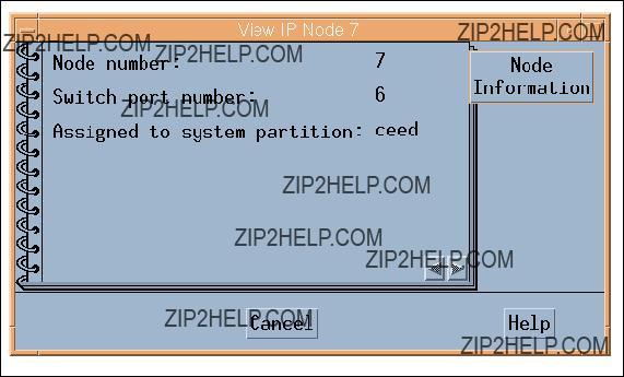
Figure 24. System Partition Aid Notebook
These attributes are listed in the Node Information tab:
???Node number
???Switch port number
???Assigned to system partition
2.4.5 SP Extension Node SNMP Manager
The SP Extension Node SNMP manager is contained in the ssp.spmgr file set of PSSP. This file set must be installed on the Control Workstation in order for the GRF to function as an extension node.
The SP Extension Node SNMP manager is an SNMP manager administered by the System Resource Controller. The purpose of the SNMP manager is to communicate with the SNMP agent on the GRF. The SNMP manager and the agent adhere to Version 1 of the SNMP protocol. The SNMP manager sends configuration data for an extension node to the SNMP agent on the GRF. The SNMP agent applies the configuration data to the SP Switch Router Adapter represented by the extension node. The SNMP agent also sends asynchronous notifications in the form of SNMP traps to the SNMP Manager when the extension node changes state. The following commands are available to control the SP Extension Node SNMP Manager:
???startsrc
58 IBM 9077 SP Switch Router: Get Connected to the SP Switch
???stopsrc
???lssrc
???traceson
???tracesoff
2.4.6 Dependent Node MIB
IBM has defined a dependent node SNMP Management Information Base (MIB) called ibmSPDepNode. This MIB contains definitions of objects representing configuration attributes of each dependent node and its state. The GRF Agent maintains the state and configuration data for each dependent node using the MIB as a conceptual database.
The MIB defines a single table of up to 16 entries representing the adapter slots in the GRF. When a slot is populated by an SP Switch Router Adapter, the entry in the table, accessed using the extension node identifier, contains the configuration attribute and state values for the adapter in the slot. Also included in the MIB are the definitions of trap messages sent by the GRF agent to the SP Extension Node SNMP Manager. A copy of the MIB is contained in the file /usr/lpp/ssp/config/spmgrd/ibmSPDepNode.my on the Control Workstation.
Other SNMP managers in the network can query this MIB table to validate the configuration and status of the dependent node and GRF. However, only an SNMP manager using the correct SNMP community name can change the values in the MIB table.
Following is a listing of MIB entries:
EntryDefinition
ibmSPDepNodeObject identifier for the dependent node in the MIB database.
ibmSPDepNodeTableTable of entries for dependent nodes.
ibmSPDepNodeEntryA list of objects comprising a row and a clause in ibmSPDepNodeTable. The clause indicates which object is used as an index into the table to obtain a table entry.
ibmSPDepNodeNameThe extension_node_identifier attribute in the DependentNode class.
ibmSPDepNodeNumberThe node_number attribute in the DependentNode class.
Router Node 59
ibmSPDepSwTokenA combination of switch_number, switch_chip and switch_chip_port attributes from the DependentNode class.
ibmSPDepSwArpThe arp_enabled attribute in the Switch_partition class.
ibmSPDepSwNodeNumberThe switch_node_number attribute in the DependentNode class.
ibmSPDepIPaddrThe netaddr attribute in the DependentAdapter class. ibmSPDepNetMaskThe netmask attribute in the DependentAdapter class.
ibmSPDepIPMaxLinkPktThe switch_max_ltu attribute in the Switch_partition class.
ibmSPDepIPHostOffsetThis attribute stores the difference between the host portion of a node???s IP address and its corresponding switch node number. When ARP is disabled on the SP Switch network, this offset is subtracted from the host portion of the IP address to calculate the switch node number.
ibmSPDepConfigStateThe six config states of the dependent node are: notConfigured, firmwareLoadFailed, driverLoadFailed, diagnosticFailed, microcodeLoadFailed, and fullyConfigured, for use in configuring the adapter.
ibmSPDepSysNameThe syspar_name attribute in the Syspar class.
ibmSPDepNodeStateThe value of nodeUp or nodeDown, to show the status of the dependent node.
ibmSPDepSwChipLinkThe switch_chip_port attribute in the DependentNode class.
ibmSPDepNodeDelayThe switch_link_delay attribute in the Switch_partition class.
ibmSPDepAdminStateThe value of up, down, or reconfigure, indicating the desired state of the dependent node. If the dependent node is not in its desired state, the SNMP agent on the GRF will trigger the appropriate action to change its state.
2.4.7 Coexistence
Figure 25 shows a
60 IBM 9077 SP Switch Router: Get Connected to the SP Switch
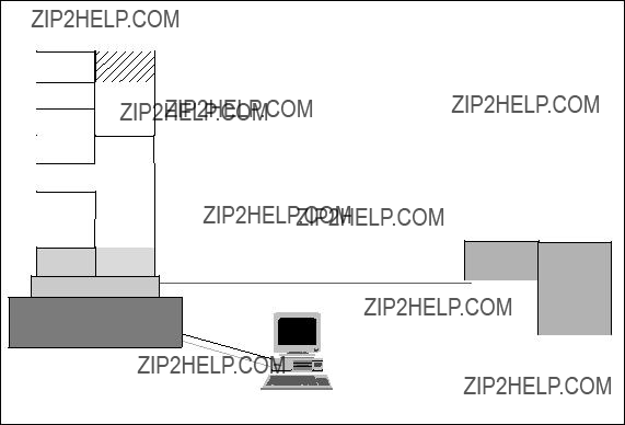
PSSP 2.4 to represent coexistence. Also, note that Node 16 is empty, because the SP Switch port for this node is used by the SP Switch router adapter in the GRF.
 PSSP 2.4 or PSSP2.3 and IX70649 on
 CWS
CWS
 Primary switch node
 Backup switch node
 PTFs for all other nodes
 for PSSP2.1 IX71246
 for PSSP2.2 IX71245
 ssp.spmgr file set installed on CWS
  Must be an SPS or
IP Switch
Control
RS232
Cable
PSSP 2.4
Figure 25. Coexistence
The dependent node is only supported in PSSP 2.3 and higher PSSP versions. To use it with nodes with PSSP versions less than 2.3 requires the use of coexistence. The following conditions are required for the dependent node to communicate with nodes with a lower version than 2.3 using coexistence:
???The Control Workstation must be at PSSP 2.3 or higher to manage dependent nodes.
???The Primary node of the SP Switch must be at PSSP 2.3 or higher, as the Primary node needs to perform some tasks for the dependent node and these functions are only available in PSSP 2.3 and higher PSSP versions.
???The Primary Backup node of the SP Switch should be PSSP 2.3 or higher so that if the Primary node fails, the dependent node can continue to function in the RS/6000 SP when the Backup node takes over.
Router Node 61

???All RS/6000 SP nodes with a version less than PSSP 2.3 in the partition need to maintain the right level of fixes (PTFs) in order for coexistence with PSSP 2.4 to take place.
???The ssp.spmgr file set must be installed on the Control Workstation.
???Because the SP Switch router adapter will only work with the
???There must be at least one free SP Switch port to install the SP Switch router adapter.
Important
When the Primary switch node fails, the Primary Backup Switch node take over as the new Primary switch node. The new Primary Backup switch node, selected from the current partition, can be a node with a PSSP level below 2.3, even though another node with a PSSP level of 2.3 or higher may exist in that partition. The only way to ensure that the new Backup switch node is at PSSP 2.3 or higher is to manually check the RS/6000 SP system. If the PSSP Version of the Primary Backup switch node is below Version 2.3 you have to chose a node with PSSP 2.3 or higher as the Primary Backup switch node.
If a node running a version of PSSP earlier then 2.3 is selected as the new primary node, the SP Switch Router Adapter will be fenced from the switch.
2.4.8 Partitioning
Figure 26 on page 63 shows a
62 IBM 9077 SP Switch Router: Get Connected to the SP Switch
Figure 26. Partitioning
Normally, RS/6000 SP nodes in different partitions cannot communicate with each other through the SP Switch. The GRF plays a unique role here by allowing RS/6000 SP nodes to communicate across partitions, when each partition contains at least one SP Switch router adapter, and these adapters are interconnected by TCP/IP.
The requirements for partitioning are the same as those for coexistence, with the addition of having at least one free SP Switch port per partition, to connect to the SP Switch router adapter.
2.5 Planning for the GRF
Before acquiring any model of the SP Switch Router, ensure that there are SP Switch ports available in the designated partition, and that the switch used in the RS/6000 SP is the
Router Node 63
Next, ensure that the following parameters are defined:
ParametersDescriptions
GRF IP addressThe IP address for the GRF administrative Ethernet.
GRF netmaskThe Netmask for the GRF administrative Ethernet.
GRF Default routeThe default route of the GRF.
SNMP community nameThis attribute describes the SNMP community name that the SP Extension Node SNMP Manager and the GRF???s SNMP Agent will send in the corresponding field of the SNMP messages. This value must match the value specified for the same attribute of the corresponding dependent node definition on the SP system. If left blank, a default name found in the SP Switch Router Adapter documentation is used.
CWS IP addressThe Control Workstation???s IP address. When a GRF contains multiple SP Switch router adapters that are managed by different SNMP managers on different RS/6000 SP CWS, each of the Control Workstation IP addresses should be defined along with a different community name for each Control Workstation.
DNSThe DNS server and domain name, if used.
SP Extension Node SNMP
Manager port #The SNMP port number used by the SP Extension Node SNMP Manager to communicate with the SNMP agent on the GRF.
This port number is 162 when the SP Extension Node SNMP Manager is the only SNMP manager on the Control Workstation. Otherwise, another port number not used in the /etc/services of the Control Workstation is chosen.
64 IBM 9077 SP Switch Router: Get Connected to the SP Switch

2.6 Planning for the Dependent Node
Next, for each dependent node on the RS/6000 SP, define the following:
ParametersDescriptions
Node #A
Slot #The slot number on which the SP Switch Router Adapter is located in the GRF.
GRF hostnameThe hostname for the GRF administrative Ethernet. A long hostname is recommended if the domain name service (DNS) is used in the network. This represents both the Administrative and SNMP agent hostname of the dependent node.
SNMP community nameThis attribute describes the SNMP community name that the SP Extension Node SNMP Manager and the GRF???s SNMP Agent will send in the corresponding field of the SNMP messages. This value must match the value specified in the /etc/snmpd.conf file on the GRF. If left blank, a default name found in the SP Switch Router Adapter documentation is used.
SP Extension Node SNMP
Manager port #The SNMP port number used by the SP Extension Node SNMP Manager to communicate with the SNMP agent on the GRF.
This port number is 162 when the SP Extension Node SNMP Manager is the only SNMP manager on the Control Workstation. Otherwise, another port number not used in the /etc/services of the Control Workstation is chosen.
Then, for the dependent node adapter, define these parameters:
ParameterDescriptions
IP addressThe IP address of this adapter.
NetmaskThe netmask of this adapter. Use the same format as that for standard RS/6000 SP nodes.
Router Node 65

2.7 Conclusion
The SP Switch Router
Unlike the SP nodes, the SP Switch Router is designed with high availability in mind. It provides balanced, fully redundant power supplies that can be hot swapped in case of failure. It provides the ability for redundant paths to an SP Switch to be configured on a single 9077; with dynamic routing protocols, a second 9077 can be used to provide a backup path in case of system failure of the primary router. In either case, each media card is hot swappable and autoconfigured after the initial install has been completed.
With its high port count on interfaces such as FDDI and Ethernet and its highly scalable performance, the SP Switch Router provides a very cost effective solution. With each media card you get a nearly linear scaling of performance with very little cost increase. An SP node by comparison runs out of CPU cycles and/or slots very quickly requiring the purchase of another entire node.
Since the 9077 (or rather the Ascend GRF) was originally designed for ISP???s, it has a full set of protocols, including dynamic routing protocols such as OSPF, BGP4 and RIPv2. It also has the memory required to hold up to 150,000 routes and the speed to access a table of this size without performance degradation. Support for media types not supported by the SP nodes also enables the SP to now be connected into networks that will be important for its future. These include support for HSSI and Sonet, which are important for the SP???s
66 IBM 9077 SP Switch Router: Get Connected to the SP Switch
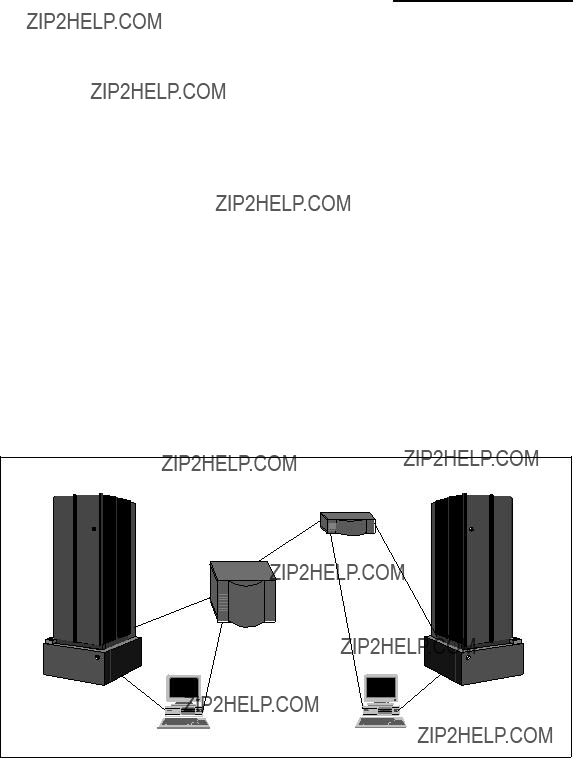
Part 2. Scenarios
This part presents some sample configurations of an RS/6000 SP system with an SP Switch Router. It is beyond the scope of this book to represent all possible applications of an SP Switch Router. Nevertheless, the basic configurations shown are building blocks for more complex networking topologies that include the SP Switch Router and may inspire more complex configurations.
All following sample scenarios were carefully chosen to match frequently occurring customer situations. They can be easily configured and modified to apply to customers??? needs. All configurations described were tested in our laboratory with the available hardware and software. We used two RS/6000 SPs, each consisting of a control workstation (CWS) and one frame with an SP Switch and several nodes (see Figure 27). All nodes and the CWS were installed with AIX 4.3.1 and PSSP 2.4. Additionally, a GRF1600 and a GRF400 running Ascend Embedded/OS V1.4.6.4. were used. Only static routing was applied in our tests. For using and configuring gated on an SP Switch Router refer to GRF Reference Guide 1.4,
Figure 27. The Laboratory Hardware Installation
But first let us get physical and see how the SP Switch Router media cards are configured.
68 IBM 9077 SP Switch Router: Get Connected to the SP Switch
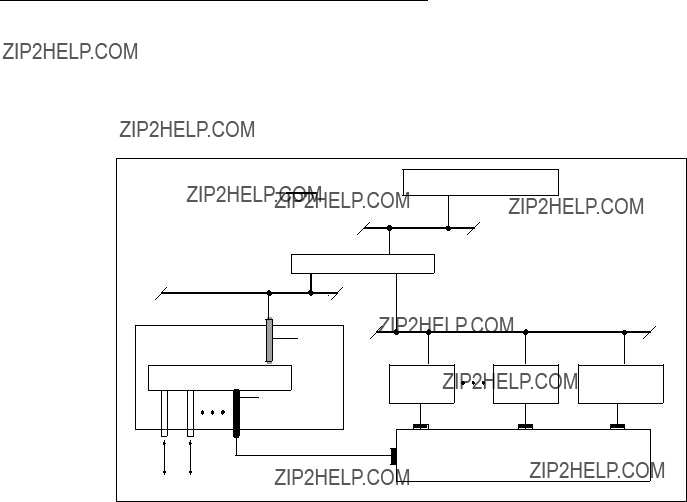
Chapter 3. Installation and Configuration
The SP Switch Router functions as an IP router to provide
Figure 28. Connecting the GRF to the SP Switch and the CWS
The SP Switch Router Adapter card also transmits data to/from other types of media cards across the SP Switch Router???s internal switch core. These media cards include HIPPI, HSSI, FDDI, ATM
Information about procedures performed from the SP CWS are found in the "Managing Extension Nodes" chapter in RS/6000 SP: Administration Guide Version 2 Release 4, GC

The intent of this chapter is to provide, or refer you to, the necessary information to enable you to attach an SP Switch Router to an IBM SP system. Coverage is provided as follows:
???Information to configure the SP Switch Router Adapter card as required for SP Switch Router functionality is complete in this chapter.
???Information to physically connect the two independent systems across cables is complete in this chapter.
???Information to start up, configure, and begin operations on the SP Switch Router is contained in GRF 400/1600 Getting Started 1.4,
???Information to configure the SP Switch Router Adapter card as required for SP system functionality is only partially described in this chapter. Detailed information is contained in the "Managing Extension Nodes" chapter in RS/6000 SP: Administration Guide Version 2 Release 4, GC23- 3897.
3.1 Initial Configuration
When a new, unconfigured GRF is powered on an initial configuration script runs automatically. You will be asked a series of questions about the configuration, as shown in the following screen.
Welcome to Ascend Embedded/OS system configuration..
Host name for this machine ?
Do you wish to configure the maintenance Ethernet interface ?
Which interface type ? (TP BNC AUI)
IP address of this machine ?
Netmask for this network ?
IP address of router (???none??? for no default route)?
Do you wish to go through the questions again ?
Which region is this machine located in ?
Which time zone ?
Next you are prompted to change the local password for root.Changing the root password is the end of the configuration script. If you need to change these parameters later, run the config_netstat script again. More details about the initial configuration are in GRF Configuration Guide 1.4,
If you log onto the GRF, a super> prompt appears. This indicates that you are in the
UNIX systems. On most of the UNIX systems you are working on the shell layer after you logged onto the system.
Many system management and configuration commands are now available. Enter a question mark (?) to retrieve a list of CLI commands. To edit configuration files, you must be in the UNIX shell. The sh command opens the UNIX shell you use to modify configurations. The following screen shows how to do this.
August 22 14:18:31 grf16 kernel: ge027: GRF Ethernet, GRIT address 0:2:7 super>
super>ls
super>no profile was specified super>sh
Copyright 1992, 1993, 1994, 1995, 1996 Berkeley Software Design, Inc. Copyright (c) 1980, 1983, 1986, 1988, 1990, 1991, 1993, 1994
The Regents of the University of California. All rights resevered.
Ascend Embedded/OS GR TA1.4.6 Kernel #1 (nit): Fri Jan 30 13:08:03 CST 1998
Ascend Embedded/OS 1.4.6
Copyright 1992,1993,1994,1995,1996,1997,1998 Ascend Communications, Inc.
IMPORTANT: By use this software you become subject to the terms and conditions of the license agreement on file /etc/license and any other License agreements previously provided to you bt Ascend Communications. #ls
.chsrc .klogin .login .profile
#
We found it more convenient to work directly at the shell layer. Therefore, we modified the .profile and commented the appropriate part that starts the CLI. For more details, see Appendix B.1, ???/root/.profile??? on page 261.
3.2
We assume the following:
???The RS/6000 SP Switch Router is powered on and has a
Figure 29 on page 73 and Figure 30 on page 74 illustrate correct connections and proper setup.
???The SP Switch Router???s basic system parameters, such as the IP address and host name, were configured during the first

system and enter these basic configuration parameters. Procedures for starting and setting up the SP Switch Router are found in GRF 400/1600 Getting Started V.14,
Ignore the prompts for network logging, since we will configure logging to a PCMCIA device; just press Enter when asked to enter the remote logging host name or its IP address.
???Remote Telnet access is working. To enable it, you have to edit the /etc/ ttys file on the SP Switch Router and modify the appropriate entries, as follows:
Adding secure to a ttypX stanza opens it for Telnet, so in this example, only two Telnet sessions at a time were allowed.
Use the following command to connect to the SP Switch Router:
xterm
This gives you a large window with a scroll bar at the left, so that you may retrieve information easier. See Appendix B.1, ???/root/.profile??? on page 261 for a modified .profile for the root user.
Hint: If you just use
Figure 29. Connecting the GRF to the Frame
???You are ready to configure media cards. Procedures to configure media cards are in this redbook; complete information is in the GRF Configuration Guide 1.4,

 One stop bit
VT100 


 terminal
GRF Console (optional)
Figure 30. Connecting the GRF Console
???The IBM SP system is up and operating.
???The SP system administrator has given you one of these pieces of information:
???The node number assigned to each SP Switch Router Adapter card to be attached to an SP Switch port
???The port location on each SP Switch reserved for specific SP Switch Router Adapter cards
3.2.1 Order of Information
Here is the sequence of steps you have to complete:
1.An installation overview of tasks involving the SP Switch Router, the SP Switch Router Adapter card, and the SP system
2.The configuration procedure for the PCMCIA 520 MB disk, which also initiates system logging
3.A description of which cables to attach between the SP Switch Router and the SP control workstation, and between the SP Switch Router Adapter card and the SP Switch

4.Methods to determine node number and SP Switch port for an SP Switch Router Adapter card
5.A
6.A list of ways to verify that the SP Switch Router Adapter card is correctly installed in the SP Switch Router
7.A description of what needs to occur to bring the card online to the SP system
3.3 Installing an SP Switch Router Adapter Card
This section contains the procedure for physical installation and minimal configuration of the SP Switch Router Adapter card for use as an SP dependent node. This includes cabling the GRF to the SP CWS and the appropriate SP Switch port.
Note: There needs to be a network path between Ethernet
3.3.1 Installation Overview
IBM support personnel who install the SP Switch Router (9077) perform the physical installation and minimal configuration described below with help from the customer???s system administrator. The system administrator must complete the following basic configuration steps:
1.Locate all the components of the SP Switch Router chip group.
2.Perform the complete physical installation of the SP Switch Router unit as described in the "Power On and Initial Configuration" chapter of GRF 400/ 1600 Getting Started 1.4,
3.Perform the procedure to configure the PCMCIA disk. The procedure is included in Section 3.3.2, ???Installing the PCMCIA Spinning Disk??? on page 76.
4.Route the Ethernet
5.Verify that the SP CWS has a connection to this same Ethernet hub. If the SP CWS Ethernet adapter is configured by the system administrator, then a ping test from the SP CWS to the configured SP Switch Router Ethernet address should be done to test Ethernet connectivity.
Physical installation and minimal configuration are complete at this point.
Review Section 3.4, ???Attaching SP Switch Router Cables??? on page 79 before connecting the SP Switch Router Adapter card cables to the SP Switch ports specified for this configuration.
3.3.2 Installing the PCMCIA Spinning Disk
Your system is shipped with a PCMCIA disk that is required to collect the system log files. This disk can hold up to 520 MB of data regarding your model of the SP Switch Router.
You can install the disk any time after the SP Switch Router is powered on and running. Logging is not enabled until you install the disk and complete this configuration procedure. Logged messages might be very helpful while you are configuring media cards. The configuration is done only once to set up local logs and dumps, and is not affected by software updates or system reboots. System logs include: gritd.packets, grinchd.log, gr.console, gr.conferrs, gr.boot and mib2d.log.
The procedure formats and initializes an external flash (/dev/wdXa), where the X is normally a 1, denoting the number of the device. You get the actual number from the mountf command. We have /dev/wd3a in our example and this value will be used for the rest of this chapter. The procedure then mounts the flash temporarily on /mnt and creates subdirectories, symbolic links and a permanent site file for storing the symbolic links.
Proceed as follows:
1.Insert the PCMCIA disk into slot A on the SP Switch Router control board (the width of the disk requires it to be installed in slot A).
2.Log in as root to the SP Switch Router, start the UNIX shell, and execute the following commands from the shell:

prompt> sh
#
#cd /
#iflash
May 29 15:54:18 grf16 kernel: wd2: no disk label
# mountf
Device /dev/wd3a mounted on /mnt
#mkdir /mnt/crash
#mkdir /mnt/portcards
#cd /var
#mv crash crash.orig
#mv portcards portcards.orig
#ln
#ln
#grsite
Device /dev/wd0a mounted on /flash. Device /dev/wd0a unmounted.
#
#cd /var/log
#pax
/mnt/./cron
/mnt/./daemon.log
/mnt/./lastlog
/mnt/./maillog
/mnt/./messages
/mnt/./secure
/mnt/./wtmp
/mnt/./grclean.log
/mnt/./mibmgrd.log
/mnt/./cli.log
#umountf
Device /dev/wd3a unmounted.
#
3.Edit the file /etc/rc.boot and see if the line mount /dev/wd3a /var/log is present; if not, add this line at the end of the file.
4.Edit the file /etc/fstab and add this line as shown in the following excerpt:
/dev/wd3a /var/log ufs rw 0 2 # PCMCIA slot A
##Each line is of the form:
##device mount_point type flags dump fsck_pass
/dev/rd0a/ ufs rw 0 0
/dev/wd3a /var/log ufs rw 0 2 # PCMCIA slot A

5.Edit the file /etc/syslog.conf to specify the location where the logs will be kept. Uncomment the local log configuration lines in the ???Log messages to Disk??? section by removing #disk# from each line, and specify /var/log as the directory for each log. The entries should now look like the following:
*.err;*.notice;kern.debug;lpr,auth.info;mail.crit /var/log/messages cron.info /var/log/cron
local0.info /var/log/gritd.packets local1.info /var/log/gr.console local2.* /var/log/gr.boot local3.* /var/log/grinchd.log local4.* /var/log/gr.conferrs local5.* /var/log/mib2d.log
6.Check that /etc/grclean.conf and /etc/grclean.logs.conf have entries pointing to files in /var/log.
The /etc/grclean.conf file entries should look like the following:
###################################################################
#port card dump files.
###################################################################
hold=4
size=1
remove=y
local=y logfile=/var/portcards/grdump.*
###################################################################
#cleanup our own log file, if necessary.
###################################################################
DEFAULTS hold=2 local=y size=10000
logfile=/var/log/grclean.log
The /etc/grclean.logs.conf file entries should look like the following:

***********************************************************************
*Log files that used to be archived by the /etc/{daily|weekly|monthly}
*scripts.
***********************************************************************
size=150000
logfile=/var/log/gr.console
size=11000
logfile=/var/log/gr.boot
7.Save all changes and reboot:
#grwrite
#reboot
8.After the SP Switch Router is up and running again, use csconfig
For a quick test, run grconslog
3.4 Attaching SP Switch Router Cables
Three types of cables must be attached:
???The administrative Ethernet LAN cable
???The SP Switch Router Adapter card to SP Switch cable(s)
???The ground strap to the SP frame
3.4.1 Ethernet Cable
Route the Ethernet

SP Control Workstation
Hub
SP Switch Router
Administrative Ethernet network
Control board
Figure 31. SP System Administrative Ethernet Connections
3.4.2 SP Switch Cable
The SP Switch Router Adapter card provides one
Each connector end has 50 fragile pins. Pins can become bent when making the connection to the media card if alignment is wrong. If an SP Switch Router Adapter card link does not work after cabling, check both ends of the cable for bent pins. When not connected, keep the plastic caps on the ends.
3.4.3 Procedure for Connecting Cards to the SP Switch
This procedure connects the SP Switch Router Adapter card(s) to the SP Switch. Before the SP Switch Router unit can begin full operation, all other router media cards must be configured with appropriate customer configuration information.
Make sure you have labeled the SP Switch cable to show which media card and SP Switch port it will be connected to. Keep in mind that for any work done on the SP Switch you should have shut down and powered off the SP System and also turned off the central power supply switch at the left front edge of the SP.
Execute the following steps to make the connections:
1.If there are any terminators on the media card or the switch assembly where you need to attach the switch cable, remove them now.

2.Using appropriate frame entry and exit holes for cable management, route the SP Switch cable between the SP Switch Router unit and the SP Switch.
3.Connect the SP Switch cable to both the media card and the correct SP Switch port, as follows:
???Connection to media card
The EMI shielding fitted inside the connector end can make insertion difficult, so be sure to insert the connector end as perpendicular as possible. (Pins can be damaged when the connector is inserted at too much of an angle.) Seat the connector firmly so the spring clips engage.
???Connection to SP Switch port
The cable ends should click onto the connectors. Determining the correct Switch port is described in Section 3.5.1, ???Determining the Switch Connection for a Dependent Node??? on page 82.
4.Make sure both ends of the cable are firmly seated by pulling on them lightly.
At this point, the SP Switch Router Adapter card configuration information must be entered on the SP CWS to enable the PSSP code and SP Switch to recognize the adapter. These tasks are discussed in Section 3.5, ???Configuration Required on the SP System??? on page 81.
3.5 Configuration Required on the SP System
This section describes the SP Switch
The SP Switch
???The SP Switch Router Ethernet IP address
???The SP Switch Router Ethernet hostname (that is, the SP Switch Router???s administrative Ethernet hostname)
???Unique node numbers for SP Switch Router Adapter cards
The SP Switch Router Adapter card configuration information enables the PSSP code and the SP Switch to recognize and communicate with this card.
3.5.1 Determining the Switch Connection for a Dependent Node
The SP Switch Router Adapter connection replaces an SP node connection to the SP Switch. Each SP Switch Router Adapter media card is referred to as a dependent node, and is assigned a node number that corresponds to its specific connection on the SP Switch.
The node number is determined by the SP system administrator based on an understanding of how node numbers are assigned in the SP System and the rules for choosing a valid, unused SP Switch port.
See Figure 32 on page 83 for a brief overview of how Switch port numbers are assigned and how to look for the best suited port number for the actual scenario.
Note: Look out for the change in numbering regarding Frame n+2 and Frame n+3!
See Figure 33 on page 84 on how node numbers are assigned independent of whether the frame is fully populated.
If proper planning has been done to assign the node number, the system administrator knows which SP frame, Switch board, and node slot corresponds to a dependent node. Given this information, you can determine which jack on the Switch board should be used by consulting the Switch Cable Charts for the SP Switch in RS/6000 SP: Maintenance Information, Volume 1, Installation and Customer Engineer Operations,
Do not attempt to connect an SP Switch Router Adapter to the SP Switch until proper planning has been done to assign the node number.
Once the node number is assigned, the SP system administrator can define the corresponding dependent node using SMIT as described in the "Managing Extension Nodes" section of RS/6000 SP: Administration Guide Version 2 Release 4,
After defining new dependent nodes on the SP, the administrator should use the Eannotator command to annotate the SP Switch topology file. With the file annotated, even if the administrator is not sure of the frame, switch board, or node slot for the dependent node, you can determine the corresponding switch connection with the procedure described in Section 3.5.2, ???Procedure to Get the Jack Number??? on page 84.
Switch
Frame n
14
12
10
8
6
4
2
0
Switch
Frame n
14
12
10
8
6
4
2
0
Switch
Frame n
12
8
4
0
Switch
Frame n
15
13
11
9
7
5
3
1
No Switch
 Frame n+1
Figure 32. Switch Port Assignments in Supported Frame Configurations
Figure 33. Node Numbering for an SP System
3.5.2 Procedure to Get the Jack Number
Following are the steps required to get the jack number:
1.From the SP control workstation, determine the dependent node???s number by entering SDRGetObjects DependentNode node_number. This produces output that looks like the following:
#SDRGetObjects DependentNode node_number node_number
4
2.From the SP CWS, determine the switch_node_number by entering
SDRGetObjects DependentNode node_number==n switch_node_number, where n is the node_number of the dependent node you just got from the previous command. This gives the following output:
#SDRGetObjects DependentNode node_number==4 switch_node_number
switch_node_number 3
#
3.From the SP CWS, determine the host name of the SP Switch primary node by entering splstdata
In this case, the primary node host name is sp21n01.
4.Log into the primary node by entering telnet node_hostname, where node_hostname is the host name of the primary node.
5.From the primary node, enter pg /var/adm/SPlogs/css/out.top.
6.In the out.top file, look for the line(s) containing Dependent Node. In this line you will find the term tb3, which is immediately followed by the value for the switch_node_number. For switch_node_number 3, the following line identifies the SP Switch jack
s 16 1 tb3 3 0
If you need help interpreting this identifying string, see PSSP Maintenance Information, Volume 2, Maintenance Analysis Procedures and Parts Catalog for an explanation of the naming standard for RS/6000 SP components.
3.6 Multiple Frames for Multiple System Connections
SP Switch Router Adapter cards in an SP Switch Router can connect to different switch boards in the same SP system. A configuration problem could arise in which the SP Switch Router Adapter cards are assigned the same node number if each card plugs into the same port position on each switch board.
The use of frames removes the configuration problem. The following example demonstrates the organization of three SP frames (1, 2, and 3) with switch boards in each.
Figure 34 on page 86 shows how the frame numbering differentiates each SP Switch Router connection:
???The SP Switch Router card connected to port J31 of SP Switch A1 is node number 9.

???The SP Switch Router card connected to port J31 of SP Switch A2 is node number 25.
???The SP Switch Router card connected to port J31 of SP Switch A3 is node number 41.
???The SP Switch Router card connected to port J15 of SP Switch A1 is node number 16.
Figure 34. How Frames Enable Connections to Multiple SP Switches
3.7
This section provides a configuration overview and the steps required to configure an SP Switch Router Adapter media card.
3.7.1 Configuration Files and Their Uses
These are the configuration files found in /etc on the SP Switch Router, discussed in this chapter:
???grifconfig.conf - identifies each logical interface on a media card
???snmpd.conf - enables SNMP capabilities
???grdev1.conf - configures SP Switch Router Adapter cards
Refer to GRF Reference Guide 1.4,
3.7.1.1 Overview of the Steps to Configure a Media Card
A detailed discussion of these steps follows this overview.
1.Edit the SNMP configuration file and start the SNMP daemon on the SP Switch Router.
2.Assign an IP address and other parameters to the SP Switch Router Adapter interface.
There are two ways to configure these parameters:
???We recommend using the procedures documented in the "Managing Extension Nodes" chapter of the RS/6000 SP: Administration Guide Version 2 Release 4,
???As an alternative, you can log in to the SP Switch Router and use a UNIX editor to edit the /etc/grifconfig.conf file. These assignments are entered in the SP Switch Router???s /etc/grifconfig.conf file:
???Interface name (gt0y0)
???IP address
???Netmask
???Broadcast address
???Argument (MTU size)
3.Change the default boot diagnostics and dump settings in profiles (optional).
To change the defaults for one card, change the settings in the appropriate Card profile; to change the defaults for all installed SP Switch Router Adapter cards, change the settings in the Dump and Load profiles.
4.Run the dev1config command while logged into the SP Switch Router. View the /etc/grdev1.conf file to verify configuration data.
For the SP Switch Router Adapter card to operate, the SP Switch Router requires a specific configuration file, /etc/grdev1.conf. The dev1config command creates this skeleton file using configuration information passed to the router in either of two ways:
???We recommend using the procedures documented in the ???Managing Extension Nodes??? chapter of the RS/6000 SP: Administration Guide Version 2 Release 4,
???As an alternative, you can log on to the SP Switch Router and use a UNIX editor to enter the parameters in the /etc/grdev1.conf file.
5.Reboot the SP Switch Router unit so that the altered configuration files are installed and used. Remember that you must use grwrite
Details about each step are provided in the next sections.
3.8 Step 1. Check SNMP in the SP Switch Router System
Check the /etc/snmpd.conf file to see if a management station and community are defined, and if traps are enabled. Network monitoring devices (management stations) can request or access the SP Switch Router???s SNMP information.
Follow the procedure described in Chapter 2, "How to configure SNMP" of the
GRF Configuration Guide 1.4,
Here are excerpts from our /etc/snmpd.conf file appropriate for the SP Switch Router connected to an SP system.
This configuration assumes that one SP CWS manages the SP Switch Router Adapter card. In the example, the IP address of the CWS is 192.168.4.137. You will see it defined in the example as MANAGER.
# Default Agent Configuration File ALLOW SUBAGENT 1.3.6.1.4.1.1080.1.1.1
WITH OTHER PASSWORD
USE 15 SECOND TIMEOUT
COMMUNITY public
ALLOW GET, TRAP OPERATIONS
USE NO ENCRYPTION
MANAGER 192.168.4.137
SEND ALL TRAPS
TO PORT 162
WITH COMMUNITY spenmgmt
COMMUNITY spenmgmt
ALLOW ALL OPERATIONS
USE NO ENCRYPTION
3.9 Put SNMP Changes into Effect
To have changes to /etc/snmpd.conf take effect, kill snmpd. It will be automatically restarted.
Log in as root, find the snmpd PID (process ID), and then kill the SNMP daemon, as follows:
#ps
326 00- S 0:00.17 snmpd /etc/snmpd.conf /var/run/snmpd.NOV
#kill 326
#Jun 13 16:13:18 grf16 mib2d[397]: mib2d: terminated by master agent
Jun 13 16:13:18 grf16 root: grstart: snmpd exited status 143; restarting.
Jun 13 16:13:18 grf16 root: grstart: mib2d exited status 0; restarting.
#
3.10 Step 2. Assign IP Addresses
Assign an IP address and other parameters to the SP Switch Router Adapter interface. As already mentioned, there are two ways to accomplish this task (one recommended, one optional).
3.10.1 Method 1: Use SP SNMP Manager - Recommended
This is the method recommended for configuring the SP Switch Router Adapter card. From a system point of view, it is appropriate to treat the SP Switch Router Adapter card as an extension node in the SP system. All configuration parameters should be entered using the SMIT panels. Remember that if you enter configuration information into SP Switch Router configuration files, you will also need to access the SMIT panels and reenter information those panels require.
Refer specifically to the "Managing Extension Nodes" chapter in the RS/6000 SP: Administration Guide Version 2 Release 4,
Following are the SMIT commands along with the data entered for the GRF 1600 in our lab environment. Refer to Appendix A, ???Laboratory Hardware and Software Configuration??? on page 233 for detailed information about our setup.
??? Command: smitty enter_extnode
Note: The Extension Node Identifier (the number of the slot in the GRF, the SP Switch Router Adapter card is seated) must be given as a
COMMAND STATUS
Before command completion, additional instructions may appear below.
The endefnode command has completed successfully.
??? Command: smitty enter_extadapter
Enter Extension Node Adapter Information
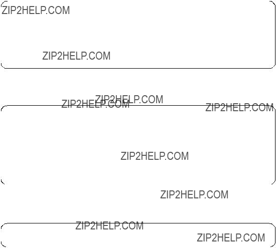
COMMAND STATUS
Before command completion, additional instructions may appear below.
The endefadapter command has completed successfully.
??? Command: smitty annotator
/etc/SP/expected.top.annotated now has a new line:

??? Command: smitty manage_extnode
Extension Node Management
Type or select values in entry fields.
Press Enter AFTER making all desired changes.
COMMAND STATUS
Before command completion, additional instructions may appear below.
enadmin command: sending a reconfigure request to the agent managing extension node 03
enadmin command: : response received from agent indicates requested action accepted for processing - command complete
Use SDRGetObjects switch_responds to see the actual status of the SP Switch:
Before the extended node can be successfully Eunfenced, more work has to be done.
3.10.2 Method 2: Edit /etc/grifconfig.conf - Optional
Edit the /etc/grifconfig.conf file to assign an IP address to each logical SP Switch Router interface. You can also provide other information about the logical IP network to which that interface is physically attached.
Each logical interface is identified in /etc/grifconfig.conf by these properties:
???Its interface name (an SP Switch Router convention, defined below)
???Its Internet address
???Its netmask
???Its broadcast/destination address
???An argument field
The format for an entry in the /etc/grifconfig.conf file is:
Remember that if you enter configuration information into SP Switch Router configuration files, you also need to access the SMIT panels and reenter information those panels require.
Interface name
The SP Switch Router interface name has five components that describe an individual interface in terms of its physical slot location in the chassis, and its specific and virtual locations on a media card.
In the SP Switch Router, the SP Switch Router Adapter card interface names look like this: gt000, gt030, gt0a0, gt0f0 (only the slot number, represented as a hexadecimal digit, changes).
Figure 35 shows the definitions of the components that comprise the SP Switch Router Adapter card interface names:
g t 0 y 0
Figure 35. Components in the SP Switch Router Adapter Card???s Interface Name
Internet address
The Internet address is the
Netmask
Netmask is the
Broadcast or destination address
The broadcast or destination address is the
The connection of the SP Switch Router Adapter card to the SP system is
When you assign an IP address to a logical interface on a
Note that any entry in the broadcast address field for HIPPI or ATM makes it a
Argument field
This field is optional for SP Switch Router Adapter cards. The argument field specifies a Maximum Transmission Unit (MTU) value different from the coded default value of 65520. When the command grifconfig runs, it passes the arguments to the ifconfig command that it spawns.
Default MTU values
Default MTUs for SP Switch Router media are:
???SP Switch Router Adapter: 65520 bytes
???HIPPI: 65280 bytes
???FDDI: 4352 bytes
???ATM
???ATM
???

Default MTUs for framing protocols are:
???Frame Relay: 4352 bytes
???HDLC: 4352 bytes
???
MTU discovery facility
MTU sizes are generally selected at the host end of the route. This is accomplished by turning on the host???s MTU discovery facility and allowing the host to send packets. The MTU discovery facility operates by default on the SP Switch Router. AIX4.3.1 provides MTU discovery; however, you have to enable it with the /etc/no command.
In effect, the discovery facility tells the router not to fragment, but instead to advise the host when the packet size is larger than the given path can handle. This allows the host to discover the largest packet that the most restrictive of the media components within the same path can handle. Once "discovered", the host then sends only packets in sizes matching the reported maximum, and so packets are not fragmented.
3.10.3 Putting grifconfig.conf Additions into Effect
Additions made to /etc/grifconfig.conf after
Use the grreset command to reset each configured SP Switch Router Adapter card by specifying the slot number where each card is installed, as follows:
grreset <card_slot_number>
3.11 Step 3. Change Profile Settings
As mentioned, this step is optional and explained in detail in GRF 400/1600 Configuration Guide 1.4,
3.12 Step 4. Run dev1config
If you followed the advice in Section 3.10.1, ???Method 1: Use SP SNMP Manager - Recommended??? on page 89, running the command dev1config should be all that needs to be done.

Nevertheless, check the file /etc/grdev1.conf. It must contain an entry for the slot in which the media card is installed. As we have our card in slot 3, the entry looks as follows:
2.21.4.1.1.3"00:00:00:01:00:00:00:06:00:01" # Switch Token
These entries show up after the SP Switch Router Adapter card gets configured on the SP Switch.
3.13 Step 5. Reset SP Switch Router System to Install Files
To install the system configuration files, first save the files and then reboot the SP Switch Router.
Save the files after you complete changing the system parameters, and again after you configure the media cards and any network services, such as filtering or dynamic routing, using grwrite
Note: grwrite only saves files in the /etc directory. If you changed files in different directories, use grsite and grsite
Use reboot
3.13.1 Saving Configuration Files
Use the grwrite

To save an alternate configuration on the internal flash based upon the currently running configuration on the internal flash device, use
grsnapshot
For more information about these commands, see GRF Reference Guide 1.4,
3.14 Verify an SP Switch Router Adapter Card on the Router
This section describes tools available with the SP Switch Router system software to check out newly installed media cards. These tools are to be used on the SP Switch Router:
???The ping command tests whether an SP Switch Router Adapter media card can process and return a message.
???The grcard [port_number] command tells you the operating state of an installed SP Switch Router Adapter card.
???The grreset command allows you to reset the card.
Note: Output from logs and other system reporting functions refer to the SP Switch Router Adapter card as DEV1, DEV_V1 or dev1.
3.14.1 Verify Media Card Operation Using ping
Check SP Switch Router Adapter media card viability using the ping command. This UNIX command is modified to support SP Switch Router board components. This use of ping only tests internal communication between the SP Switch Router control board and the specified media card. It does not test message routing between media cards or communication between media cards and external devices.
Note: The ping command does not disturb normal SP Switch Router operations.
The ping
Follow these steps:
1. Log in as root to the SP Switch Router.
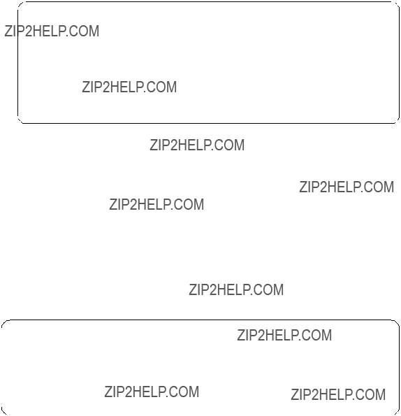
2.Enter a ping command. Specify the appropriate media card by its chassis slot number; for example, to act on the SP Switch Router Adapter media card in slot 3, enter ping
This is what you see when the media card responds:
# ping
GRID ECHO 3 (0:0x3:0): 64 data bytes, 3 packets
68 bytes from 0:0x3:0: time=0.619 ms
68 bytes from 0:0x3:0: time=0.498 ms
68 bytes from 0:0x3:0: time=0.640 ms
68 bytes from 0:0x3:0: time=0.640 ms
3 packets transmitted, 3 packets received, 0% packet loss
#
To act on the GRF control board, enter ping
Refer to GRF Reference Guide 1.4,
3.14.2 Check Media Card Status Using grcard
The grcard command returns information about the status of all installed media cards. Output from logs and other system reporting functions refers to the SP Switch Router Adapter card as DEV1, DEV1_V1 or dev1.
Here is a sample of the slot, media, and state information returned from the grcard command:
The SP Switch Router Adapter card resides in slot 3 and its state is reported as running.
Refer to the command descriptions in the GRF Reference Guide 1.4, GA22- 7367 for a description of grcard and the meaning of the different media states.
3.14.3 Reset Media Card Using grreset
Use the grreset command to reset a media card from the UNIX prompt:
1.Log in as root on the SP Switch Router.
2.Enter the grreset command.
Specify the appropriate media card by its chassis slot number. To reset all the media cards, enter grreset all; to reset the media cards in slot 0, enter grreset 0; to reset the card in slot 4 and dump its memory, use grreset
Note: The grreset command can be used on a media card without disturbing normal SP Switch Router function.
You should, however, fence the SP Switch Router Adapter card before you issue a grreset command against it. This prevents some unexpected behavior of the SP primary node. Use the following command on the CWS:
Efence
With the autojoin flag set, the SP Switch Router Adapter card is supposed to integrate automatically into the SP Switch network after a grreset command.
Without the autojoin flag, Eunfence or Estart need to be issued.
Refer to the command section in the GRF Configuration Guide 1.4, GA22- 7366 for a description of grreset. Refer toRS/6000 SP: Command Reference Version 2 Release 4,
Estart.
3.14.4 Using grstat to Display GRF Statistics
You might want to periodically watch what is going on on the SP Switch Router Adapter card. Use the command grstat

Below is an actual example:
# grstat
ipstat
count description
11095886 total packets received
51 packets dropped
3678330 packets forwarded normally
4 packets forwarded locally to card
1214 packets handled by the card
3.15 Bringing the SP Switch Router Adapter Card Online with the SP
After the SP Switch Router Adapter media card completes initialization, its state machine enters the Configured state. The media card sends an
The SP system administrator now decides which action is required to bring the SP Switch Router Adapter???s interface online.
If the SP Switch Router Adapter was previously fenced from the Switch network with the
one of the following actions to bring the SP Switch Router Adapter card online:
???A switch initialization
???An unfencing sequence
???Another Switch management sequence
The appropriate action depends on what state the SP system is in with respect to the dependent node. For example, if no Estart command has been issued to reinitialize the SP Switch since the dependent node (the SP Switch Router Adapter) was installed, then an Estart command is needed. If the dependent node was fenced from the SP Switch without the
Many different states are possible. Consult RS/6000 SP: Installation and Migration Guide Version 2 Release 4,
The SP Switch Router Adapter media card remains in ConfigState=FullyConfigured,until it is brought online via a switch initialization or unfencing sequence.
Should the
3.15.1 Checking Connectivity to the SP System
The procedure in this section is useful when a problem is suspected with the SP Switch Router Adapter media card, its connection to the SP Switch, or its connection to the SP Switch Router hardware. This section is intended for hardware service personnel, although parts may be applicable to customer problem determination.
Before beginning this procedure, it may be helpful to verify the configuration of the media adapter. If you are unable to find a configuration problem or are unable to correct the configuration due to potential hardware problems, this procedure should be used to check the connection to the SP Switch.
Each SP Switch Router Adapter media card is considered a dependent node for the SP System. Each dependent node has a node_number and other configuration and status information that is unique to that dependent node.
3.15.1.1 Procedure
The following steps might give you guidance in solving some of the most common connectivity problems:
1.Check the SP Switch cable for obvious problems such as a loose or disconnected connector, missing shielding or bent pins.
2.Check the
3.If there is no terminal directly attached to the SP Switch Router, check the SP Switch Router host name from the SP CWS. From the CWS, enter
SDRGetObjects DependentNode node_number reliable_hostname. This will return the node numbers and the corresponding host names for the SP Switch Router systems.
4.Test Ethernet connectivity by performing a ping test from the SP CWS to the SP Switch Router administrative Ethernet address.
5.Check the status of the SP Switch Router Adapter LEDs.
Use the tables in the "SP Switch Router Adapter LEDs" section in Appendix C to determine the state of the card.
Generally, RX ST0/ST1/ERR and TX ST0/ST1/ERR indicate a problem. The problem might be due to connection, configuration, hardware, or software.
To further test the SP Switch Router Adapter card hardware, you can reset or reseat the card, and then use the tables under "LED activity during boot" in Appendix C to interpret the results.
6.From the CWS, use an Eunfence and/or Estart command to bring the dependent node back into the configuration.
From the CWS, issue the command SDRGetObjects switch_responds and check for correct values. If switch_responds is 1 or shows up green in Perspectives, then the dependent node is active again.
7.You may need to log in to the SP Switch Router to perform additional analysis before determining whether any hardware needs replacement.
8.If problems remain, you will have to contact the next level of Customer Support for further direction. They may log into the SP Switch Router to perform additional analysis. If you were directed here by the RS/6000 SP
Maintenance Information Manual Dependent Node MAP, return to that procedure.
For more information about configuration as related to the SP, see RS/6000 SP: Administration Guide Version 2 Release 4,
For additional information on troubleshooting your configuration, see RS/ 6000 SP: Diagnosis and Messages Guide Version 2 Release 4,

Chapter 4. Configuration of
This chapter covers the installation and configuration of selected IP Forwarding media cards in an SP Switch Router. For detailed information refer to GRF Configuration Guide 1.4,
4.1 Ethernet
This section provides the information needed to configure the Ethernet
As Ethernet seems to be best known all over the world and configuring this type of card is really straightforward, this will was the easiest way to get interfaces other than switch connected to the GRF.
4.1.1 Physical and Logical Interfaces
Physical Interfaces
The
Logical Interfaces
A logical interface is configured by its entry in the grifconfig.conf file, where it is assigned an IP address and netmask. A logical interface is uniquely identified by its Ethernet interface name.
Interface Name
The generic form of an Ethernet interface name is ge0xy. See Figure 36 on page 106 for the naming conventions on the Ethernet card.

g e 0 x y
Figure 36. Components of the Ethernet Interface Name
The interface name is used in the /etc/grifconfig.conf file to specify an IP interface. Interface 7 on the Ethernet card in slot 3, for example, would be added to this file as:
Note: Interface names are case sensitive. Always use lower case letters when defining interface names.
4.1.2 Configuration File and Profile Overview
These are the steps to configure Ethernet interfaces:
1.Identify each logical interface
Edit /etc/grifconfig.conf to identify each logical interface by assigning:
???An IP address
???The GRF interface name
???A netmask, as required
???A destination or broadcast address, as required
???A Maximum Transmission Unit (MTU), if needed
2.Specify Ethernet card parameters in the card profile
These are the configurable items in a card profile for an Ethernet media card (all but the first optional):
???Configure interface mode: autonegotiate, 10 or 100
???Specify verbose option for messages from the Ethernet card
???Specify ICMP throttling settings
???Specify selective packet discard percentage
106 IBM 9077 SP Switch Router: Get Connected to the SP Switch
???Change
???Change dump variables
3.Load profile
Global executable binaries are set in the Load profile in the
4.Dump profile
Global dump settings are in the Dump profile. These settings are usually changed only for debug purposes. The
The file system accommodates the default setting of zero (0), which actually stores two dumps per day (the current dump and the first dump of the day). Use caution if you change the recommended default.
If you want to change dump settings for one Ethernet card (per interface), make the change in the Card profile, in the dump field.
For a detailed discussion of these steps, refer to GRF Configuration Guide 1.4,
4.1.3 Installing Configurations or Changes
In the command line interface (CLI), which you can recognize by its super> prompt, use set and write commands to install configuration parameters.
To save the files in the /etc configuration directory, use grwrite
Additionally, when you enter configuration information or make changes, you must also reset the media card for the changes to take place.
Enter grreset <slot_number> to make this happen.
Hint: We have found situations where grreset was not able to reconfigure cards, ports or the running kernel. So if you are in doubt, it is always safe to reboot
4.1.4 Assign IP Addresses - grifconfig.conf
Configure each logical interface in the grifconfig.conf file by assigning it an IP address, a GRF interface name, and, if required, a netmask and destination or broadcast address. Here is an entry from our /etc/grifconfig.conf file:

4.1.5 Specify Ethernet Card Parameters
As already mentioned, modifying the following profiles is optional.
???Card Profile - Card Parameters
???Load Profile -
???Dump Profile - Dump Defaults
Only for the configuration of the interface mode these profiles need to be modified. You would at least like to know whether FDX and HDX settings are suited to your environment and change them, if needed.
We advise that you set the ports explicitly to the values you expect them to have according to your network layout. We prefer to have control over the network, instead of it controlling us (which might be wishful thinking).
Set the Negotiation or Transfer Rate
Set the negotiation or transfer rate in the ports/ether field. By default, the setting for each interface is autonegotiate:
super> read card 7 CARD/7 read super>list ports 1 port_num = 1
sonet = { "" "" 1 sonet
ether = { autonegotiate }
hippi = {1 32
At this level, use the set command to look at the interface options:
super> set
108 IBM 9077 SP Switch Router: Get Connected to the SP Switch
Ethernet interface configuration. Enumerated field, values: autonegotiate: autonegotiate
CARD2/ written super> quit
#
The configuration of the Ethernet card is now completed. Issue grwrite
4.1.6 Some maint Commands for the Ethernet Media Cards
The maint commands operate on the SP Switch control board and require the card???s slot number, which you may find with the grcard command.
Prepare to use maint with the following steps:
??? First, switch to maint???s GR 66> prompt with the grrmb command.
???At the GR66> prompt, change to the prompt for the specific card you are interested in. For a card in slot 7, this would be the command port 7.
???As a result, the following message along with the changed prompt is returned:
Current port card is 7 GR 7>
???At this prompt maint commands can be issued.
???To leave the GR 7> prompt, enter quit.
The following maint commands were most useful for us:
maint 1
maint 101
maint 3
maint 4

you see the output for all eight. The input port side is reported on first.
maint 5
maint 7
maint 8
4.2 ATM
This section provides information needed to configure the ATM
4.2.1 Physical and Logical ATM Interfaces
Figure 37 shows the organization of physical and logical ATM interfaces on the ATM
Figure 37. ATM
Physical Interfaces
The ATM
Logical Interfaces
Logical interfaces provide a simple way of mapping many IP addresses onto a single ATM port. A logical interface serves as the connection between ATM and IP. Each logical interface is assigned a unique IP address in grifconfig.conf. All interface names are case sensitive. Always use lower case letters when defining interface names.
110 IBM 9077 SP Switch Router: Get Connected to the SP Switch

See Figure 38 for the naming conventions of an ATM interface.
g a 0 x yz
Figure 38. Components in the ATM
Virtual Circuits
A virtual circuit (VC) exists between two ATM devices. It is the
Each VC is identified by a pair of numbers, representing a virtual path identifier (VPI) and a virtual circuit identifier (VCI). A slash (/) is used to separate the two numbers, for example, 0/2645. The VPI/VCI must be unique on a link. Because it is acceptable to use the same VPI/VCI on different links, a GRF can have the same VPI/VCI active on each physical interface.
The ATM
Virtual Paths
A virtual path (VP) connects two end stations, which may be separated by one or more network devices such as a router or switch. A path consists of one or more virtual circuits, as you can see in Figure 39.
Figure 39. Components Forming a Virtual Path
VPIs 0 through 15 are available for configuration use. VPIs are assigned in the /etc/gratm.conf file with regard to their VCI.
VCIs
VCIs name VCs. VCIs are also assigned in the /etc/gratm.conf file. On VPI 0, VCI 0 through VCI 32767 can be used; on VPIs
Note: Virtual circuits
Permanent Virtual Circuits
Permanent virtual circuits (PVCs) are created statically. PVCs are configured in /etc/gratm.conf. The GRF supports Inverse ATM ARP (InATMARP) to determine the IP address of the other end of the VPI/VCI. If the other device does not support InATMARP, an ARP entry for the IP and VPI/VCI of the other device must be made in /etc/grarp.conf.
Note: VPI/VCI pairs must be unique per physical port, and you cannot have two or more circuits with the same VPI/VCI in the same logical interface.
Switched Virtual Circuits
Switched virtual circuits (SVCs) are created or destroyed dynamically using standard signaling protocols. These protocols allow ATM devices to create or destroy connections in response to traffic demands. The VPI/VCI for a given SVC is determined at the time of the connection setup, and thus requires no manual configuration in /etc/gratm.conf. However, it is necessary to specify which of the UNI signaling standards (UNI3.0 or UNI3.1) you wish to use, and to assign an ARP server. Both sides of the ATM link must use the same version of the signaling protocol. If you do not wish to use SVCs, set the signaling for that interface to NONE.
UNI signaling uses ATM Format NSAP addresses, not IP addresses, and requires the use of an ARP server. The ARP server maps an IP address to an NSAP address so that ATM signaling can create or use the appropriate SVCs for traffic destined for the given IP address. The ARP server???s NSAP address must be configured in the Service section of /etc/gratm.conf.
PVCs and SVCs can be used simultaneously on the same physical interface (port). PVCs and SVCs can also coexist on the same logical interface.
Verifying an ATM Configuration
maint commands enable you to verify an ATM configuration. They are described in Section 4.2.7, ???Some maint Commands for the ATM
112 IBM 9077 SP Switch Router: Get Connected to the SP Switch
4.2.2 Installing Configurations or Changes
In the command line interface (CLI), use set and write commands to install configuration parameters.
To save the /etc configuration directory, use grwrite
Additionally, when you enter configuration information or make changes, you must also reset the media card with the command grreset <slot_number> for the change to take place.
4.2.3 Configuration Files and Profiles
Following are the steps to configure an ATM card. They are listed here complete, although you can bring up an ATM connection with a subset. For detailed information, see GRF Configuration Guide 1.4,
Proceed as follows:
1.Identify each logical interface.
Edit grifconfig.conf, to identify each logical interface, by assigning:
???An IP address
???The GRF interface name
???A netmask, as required
???A destination or broadcast address, as required
???An MTU, if needed
See Section 4.2.4, ???Assign IP Addresses - grifconfig.conf??? on page 114 for the details.
2.Specify ATM card parameters in the Card profile (all optional):
???Specify ICMP throttling settings
???Specify a selective packet discard percentage in the
???Change
???Change dump variables
3.Configure PVCs and SVCs in /etc/gratm.conf.
Edit the file /etc/gratm.conf and add entries for the following keywords for a minimum configuration:
???Traffic_Shape
???Interface
???PVC
The following screen shot shows an excerpt from our scenario:

Traffic_Shape name=high_speed_high_quality \ peak=155000 sustain=155000 burst=2048 qos=high
Traffic_Shape name=low_speed_high_quality \ peak=15500 qos=high
Interface ga010 traffic_shape=high_speed_high_quality
Interface ga0180 traffic_shape=low_speed_high_quality
PVC ga010 0/132 proto=ip traffic_shape=high_speed_high_quality
PVC ga0180 0/134 proto=ip traffic_shape=low_speed_high_quality
4.Load profile (optional).
Global executable binaries are set in the Load profile in the
If you want to change the
5.Dump profile (optional).
Global dump settings are in the Dump profile. These settings are usually changed only for debug purposes. The
If you want to change dump settings for one ATM card (per interface), make the change in the Card profile, in the dump field.
4.2.4 Assign IP Addresses - grifconfig.conf
Edit the grifconfig.conf file to assign an IP address to each logical ATM interface. You can also provide other information about the logical IP network to which that interface is physically attached, or specify a different MTU in the arguments field, for example.
When you configure a logical interface on a
114 IBM 9077 SP Switch Router: Get Connected to the SP Switch
interface basis. This field is also used to specify ISO when an ISO address is being added to an interface???s IP address. Specify the MTU value as mtu xxxx. Leave the arguments field blank if you are not using it.
The following excerpt from our /etc/grifconf.conf file shows the format of an entry:
As you can see, we have defined the first logical interface to be broadcast and the second interface to be
4.2.5 Specify ATM Card Parameters
Changing the following profile is not mandatory. You can safely use the defaults. Refer to GRF Configuration Guide 1.4,
4.2.6 Configuring PVCs
To configure a logical interface that supports PVCs, make entries in these configuration files:
1./etc/grifconfig.conf
Assign an IP address to the logical interface.
2./etc/grarp.conf
Supply
Put an entry into /etc/grarp.conf only if the remote destination does not support InATMARP, which the GRF does.
3./etc/gratm.conf
???Traffic shaping section
Set the traffic shaping name and quality of service parameters. The name may be any meaningful string you like.
???Signaling section
Set protocol=NONE on the signaling entry for the appropriate card and connector combination.
???Interface section
Define the traffic shaping profile for the logical interface to which the media card???s PVCs are assigned.
???PVC section
Specify characteristics for each PVC, including:
???Assigned logical interface name
???VPI/VCI
???Protocol supported
???Whether AAL is used
???Assigned traffic shaping profile (only if it would be different from the profile given previously to the logical interface in the Interface section)
Templates of these configuration files are in GRF Reference Guide 1.4,
Hint: Use gratm
The actual data for configurations we tested will be presented in Section 5.1.3, ???SP Switch - ATM Connection??? on page 167 and Section 7.1, ???ATM
4.2.7 Some maint Commands for the ATM
The maint commands display a range of information about the media card. The ATM
To use maint, follow these steps:
???First, switch to the maint prompt with the grrmb command. A new prompt,
GR 66>, will appear.
???Then change the prompt port to the ATM media card you are working with. For example, if you are working with a card in slot 3, enter GR 66> port 3.
116 IBM 9077 SP Switch Router: Get Connected to the SP Switch
The following message is returned along with the changed prompt:
Current port card is 3
GR 3> .
??? To leave any maint prompt and return to the shell, enter quit.
Following are just a few maint commands we have found useful; of course, your experiences may vary.
To see the list of maint commands for the receive side, enter maint 1; to see the list of maint commands for the transmit side, enter maint 101.
The maint 3 command gives you useful options for looking at a variety of active interfaces. To look at media information per port, use maint 4 and the port number, 0 or 1. Use maint 4 0 to see the information for the card???s port 0.
To display switch statistics, use maint 5, which will give you information about the number of packets to and from the switch (in the GRF).
You can return information about VPI/VCIs on a per port, per side basis with maint 13 0 or maint 13 1, respectively. For information about traffic statistics use maint 14 0 or maint 14 1, respectively.
4.2.8 Using grrt to Display the Route Table
Use the grrt
118 IBM 9077 SP Switch Router: Get Connected to the SP Switch

4.2.9 Using grstat to Display GRF Statistics
Use the grstat
4.3 ATM
This section provides information needed to configure the ATM
The ATM
The
4.3.1 Physical and Logical ATM Interfaces
Figure 40 on page 120 shows the organization of physical and logical ATM interfaces on the ATM
Figure 40. ATM
Physical Interfaces
The ATM
Virtual Circuits
The ATM
Virtual Paths
VPIs 0 through 3 are available for configuration use.
VCIs
On VPI 0, VCI 0 through VCI 1023 can be used; on VPIs
Note: Virtual circuits
4.3.2 Installing Configurations or Changes
In the command line interface (CLI), use set and write commands to install configuration parameters.
To save the /etc configuration directory, use grwrite
Additionally, when you enter configuration information or make changes, you must also reset the media card with the command grreset <slot_number> for the change to take place.
4.3.3 Configuration Files and Profiles
The following steps to configure an ATM
Proceed as follows:
120 IBM 9077 SP Switch Router: Get Connected to the SP Switch

1.Identify each logical interface.
Edit /etc/grifconfig.conf, to identify each logical interface by assigning:
???An IP address
???The GRF interface name
???A netmask, as required
???A destination or broadcast address, as required
???An MTU, if needed
2.Configure PVCs and SVCs in /etc/gratm.conf.
Edit the file /etc/gratm.conf and add entries for the following keywords for a minimum configuration:
???Traffic_Shape
???Interface
???PVC
The following screen shot shows an excerpt from our scenario:
Traffic_Shape name=bigg_speed_high_quality \ peak=622000 sustain=622000 burst=2048 qos=high
Interface ga020 traffic_shape=bigg_speed_high_quality
PVC ga020 0/132 proto=ip traffic_shape=bigg_speed_high_quality
Note: the ATM
Hint: Use gratm
The actual data for the configuration we tested will be presented in Section 7.2, ???ATM
4.4 FDDI Configuration
This section provides information needed to configure the FDDI media card. The card has four physical interfaces that can be connected to either switches, hubs or hosts, and may be set up as four single attached stations (SAS), as two SASs and one dual attached station (DAS), or as two DASs. It operates at 100Mbit/s.
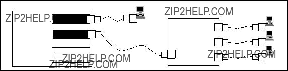
It might be useful to give a short overview of possible FDDI connection options, namely SAS, DAS, optical bypass and dual homing, and show a picture explaining these scenarios.
Single Attach (SAS)
Single attach FDDI interfaces can be either master (M) ports or slave (S) ports. They require a cable with a corresponding master or slave connector. Single attach cables have an M connector on one end and an S connector on the other. With no key installed, both M and S connectors fit the FDDI interface. So if you do not use the colored keys that come with every FDDI cable and mark the connectors and receptacles as to their use correctly, you may well be unable to get a working physical connection, because you have connected the wrong fiber ports together.
To key a connector, fit the red type A, the blue type B or the green type M key inserts accordingly. An unkeyed connector is of type S.
A single attach FDDI interface on the GRF is a master port when it directly connects to a workstation. As shown in Figure 41, it is a slave port when connected to the master port of an FDDI concentrator which, in turn, connects to the slave ports of SAS workstations.
Figure 41. Master/Slave Connectors for SAS Interfaces
Dual Attach (DAS)
Dual attach interfaces connect to form two unbroken
Dual attach cables have an A connector on one end and a B connector on the other. As shown in Figure 42 on page 123, the A port connects a station to its downstream neighbor; the B port connects a station to its upstream neighbor.
To create a logical ring, A must connect to B and B must connect to A. Otherwise, the network does not operate as a logical ring, but segments into unconnected subrings.
122 IBM 9077 SP Switch Router: Get Connected to the SP Switch
Figure 42. A/B Connectors for DAS Interfaces
Configuring SAS versus DAS
Only the top or bottom pair of FDDI interfaces can be set to dual attach. Interfaces 1 and 2, for example, must not be paired. It is recommended to set unused FDDI interfaces to single in the Card profiles (which is the default anyway).
All possible FDDI configurations are shown in Figure 43.
Figure 43. Allowed SAS and DAS Configurations
In the Card profile, specify SAS or DAS as single or dual in the ports/fddi field. This example shows how to set interfaces 0 and 1 as DAS and do a write at the end to save the changes. The following shows the path to change the setting of a port from SAS to DAS.
You have to exit from the # prompt to the super> prompt of the GRF and read card <slot_number>. We assume the FDDI card seated in port 0, therefore the command is read card 0.
The system responds with:
CARD/0 read
super>
Now provide the lower number of the two ports you want to assign DAS to, with list ports 0, and then issue list fddi to get the following from the system:
super> list ports 0 port_num = 0
sonet = { "" "" 1 sonet
ether = { autonegotiate }
hippi = { 1 32
super> list fddi
As you can see, the
super> set
port_num = 0
sonet = { "" "" 1 sonet
ether = { autonegotiate }
hippi = { 1 32
super> write CARD/0 written super>
You have to go through the same procedure again and replace references to port 0 with port 1.
Use sh to return to the operating system of the GRF and grreset the card, or use exit to log off from the router.
Once you get more familiar with the GRF, you may prefer the following quick way:
super> read card 0
CARD/0 read
super> set port 0 fddi
super> set port 1 fddi
124 IBM 9077 SP Switch Router: Get Connected to the SP Switch
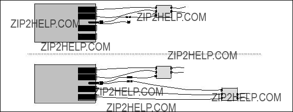
super> write
CARD/0 written
super>
Optical bypass
Optical bypass capability has to be provided externally. The FDDI face plate has a
As shown in Figure 44, two bypass switches can be attached with the an
A bypass switch allows the GRF to remove itself from the dual ring during a failure or maintenance without causing the ring to "wrap" at upstream and downstream neighbors. Should a GRF failure occur, the bypass switch connects upstream and downstream neighbors on both the primary and secondary rings, and allows the GRF node to remove itself from the ring gracefully, while still retaining ring continuity.
A node failure without a bypass switch causes the dual ring to "wrap". A wrapped ring absorbs the secondary ring into the primary ring and no longer has a backup ring.
FDDI media card
FDDI media card
Ring 1
Switch Module
Ring 1
Switch Module 1
Ring 2
Switch Module 2
Figure 44. Optical Bypass Switch Attachments
Dual homing
Dual homing provides redundant connectivity between an FDDI media card and a single ring.

Configure the FDDI media card for dual attach, but use two single attach (SAS) cables to connect to two M ports. As shown in Figure 45, the M ports can be on either one or two FDDI concentrators on the ring.
Figure 45. Dual Homing Configurations
4.4.1 Separate Networks versus Bridging
With all that said, it should be very clear now that every port needs to be attached to a distinct network, either physical or logical (divided by subnet masks). This gives you distinct paths to every network and requires setting up routes.
If you are running a flat FDDI backbone and have the need to connect all four ports into it, you must configure the card???s interfaces to use transparent bridging, thus "bundling up" the bandwidth of the four interfaces.
The actual steps to implement bridging will be covered later; refer to Section 4.6, ???Configuring Bridging??? on page 142.
4.4.2 Naming the FDDI Interfaces
Each interface may be named or numbered in four different ways:
???By its physical location on the FDDI card
???By a
126 IBM 9077 SP Switch Router: Get Connected to the SP Switch

???By a logical interface number assigned after the SAS/DAS settings are numbered (used in the /etc/grifconfig.conf file)
???By a unique IP address assigned to each logical interface
Figure 46 shows files where various numbers are used to configure the interfaces on an FDDI media card.
Figure 46. Assigning Numbers to FDDI Interfaces
4.4.3 Physical Interface Numbers
The physical interface number identifies the specific FDDI fiber optic attachment component according to its location on the media card; it may be from
Starting at the top of the media card, each physical interface is numbered consecutively, beginning with 0, as shown in Figure 47 on page 128.

Figure 47. Physical Interface Numbering on the FDDI Media Card
The diagram shows physical interface numbering to be
4.4.4 GRF Interface Name
The GRF interface name has five components that describe an individual FDDI interface in terms of its place on the media card and in the GRF router.
Follow the naming conventions shown in Figure 48 and keep in mind that all interface names are case sensitive and that you must use all lowercase.
g f 0 x y
Figure 48. GRF Interface Name for FDDI Interfaces
The interface name and IP address are specified in the /etc/grifconfig.conf file.
4.4.5 Configuration Files and Profiles
Following are the steps to configure FDDI cards. They are listed here complete, although you can bring up an FDDI connection with a subset. For detailed information, see GRF Configuration Guide 1.4,
Proceed as follows:
1. Identify each logical interface.
128 IBM 9077 SP Switch Router: Get Connected to the SP Switch
Edit /etc/grifconfig.conf to identify each logical interface by assigning:
???An IP address
???The GRF interface name
???A netmask, as required
???A destination or broadcast address, as required
???An MTU, if needed
2.Specify FDDI card parameters in the Card profile. All but the first two are optional and default to the most common settings, so normally you should be just fine omitting this step.
???Specify SAS and DAS settings as single or dual, with single being the default.
??? Manually enable optical bypass on or off with off being the default.
???Specify ICMP throttling settings.
???Change
???Change dump variables.
3.Load profile (optional).
Global executable binaries are set at the Load profile in the
If you want to change the
4.Dump profile (optional).
Global dump settings are in the Dump profile. These settings are usually changed only for debug purposes. The
If you want to change dump settings for one FDDI card (per physical interface), make the change in the Card profile, in the dump/config field.
4.4.6 Assign IP Addresses - grifconfig.conf
Edit the /etc/grifconfig.conf file to assign an IP address to each logical FDDI interface. You can also provide other information about the logical IP network to which that interface is physically attached, or specify a different MTU in the arguments field, for example.

The arguments field is also used to specify ISO when an ISO address is being added to an interface???s IP address. Specify the MTU value as mtu xxxx. Leave the arguments field blank if you are not using it.
The following excerpt from our /etc/grifconf.conf file shows the format of an entry:
As you can see, we used three interfaces and left out the specification for the MTU size on the last two, as 4352 is the default for FDDI.
4.4.7 Specify FDDI Card Parameters
The following steps are, as mentioned, optional, and in an SAS environment without optical bypass you can safely use the defaults.
If there is a need to set ports from SAS to DAS, refer to GRF Configuration Guide 1.4,
4.4.8 Installing Configurations or Changes
In the command line interface (CLI), which is the working environment on the GRF with the super> prompt, use the set and write commands to install configuration parameters onto the media card.
If you apply changes to files in the /etc directory, do not forget to issue grwrite
Additionally, when you enter configuration information or make changes, you must also reset the media card for the changes to take place. Enter
grreset <slot_number> to do so.
Hint: We found that some changes did not go into effect until the GRF was rebooted, although the documentation indicated otherwise. So do not hesitate to reboot if things seem not to work as they should.
130 IBM 9077 SP Switch Router: Get Connected to the SP Switch
This completes the procedure to configure FDDI cards, and as with the ATM card, we would like to introduce some of the maint commands we found to be useful.
4.4.9 Some maint Commands for the FDDI Media Card
The maint commands display a range of information about the FDDI media card. The FDDI card has an individual processor for the transmit and receive side, and two sets of maint commands. One set, the maint 1 commands, covers the receive (RX) side, while the second set, the maint 70 commands, covers the transmit (TX) side.
To use maint, follow these steps:
???First, switch to the maint prompt with the grrmb command. A new prompt, GR 66>, will appear.
???Then change the prompt port to the FDDI media card you are working with. For example, if you are working with a card in slot 0, enter port 0 at the GR> 66 prompt.
The following message is returned along with the changed prompt:
Current port card is 0 GR 0>
???To leave any maint prompt and return to the shell, enter quit.
Following are just a few maint commands we have found useful; of course, your needs may vary.
To obtain a list of FDDI CPU0 maint commands, enter maint 1. Enter the maint 70 command to switch to the set of CPU1 commands. The maint 3 command returns configuration information for each interface; to list statistics per FDDI interface, use maint 4; to list switch interface statistics, enter
maint 5.
Clear all statistics with the maint 7 command. Display the current ARP table???s content with maint 70 8. Reset individual FDDI interfaces using maint 12 and the physical interface number
4.4.10 Using grrt to Display the Route Table
Use the grrt
132 IBM 9077 SP Switch Router: Get Connected to the SP Switch
4.4.11 Using grstat to Display GRF Statistics
Use the grstat
#
4.5 HIPPI Configuration
This section provides the steps to configure the High Performance Parallel Interface (HIPPI) media card of a GRF.
4.5.1 Introduction to HIPPI
HIPPI poses interesting configuration problems because of the number of ways HIPPI connections can be established. Several addressing schemes can be used, depending upon how a site needs to organize and connect equipment to support a range of user needs.
Not only are there several addressing schemes, but a HIPPI media card can be configured to process all of them. The HIPPI media card is capable of handling both
these modes. Hosts must pass on the appropriate information for the GRF media cards and other HIPPI devices to operate in the desired way.
HIPPI offers many configuration options. The ANSI HIPPI standards and RFCs describe implementation details, that support source routing, logical addressing, IP routing, and raw (switch) mode operations.
4.5.1.1 Connection Processing
The GRF processes connections; it does not process data. It accepts data and establishes a connection point to which it can transfer data.
The HIPPI media card establishes connections and transfers packets. A HIPPI media card processes one HIPPI connection at a time. It does not begin another process until the first connection completes.
There are two types of connections:
???IP connections
???Raw connections
In internetworking, the main difference between the two connections is that data from a HIPPI host can be transferred to any other
So the toughest step in the configuration of a HIPPI media card is to compose the correct HIPPI
4.5.1.2 Starting a HIPPI Connection
The HIPPI standard requires that a HIPPI connection be established between a HIPPI source and a HIPPI destination before any data is transmitted. Every connection "request" signal sent to a HIPPI media card is accompanied by a HIPPI
The sequence that establishes a HIPPI connection is as follows:
1.The HIPPI source activates the REQUEST line to a destination while at the same time placing a
2.The HIPPI destination sees the REQUEST signal, reads the
Data coming from an external HIPPI I/O channel may be formatted into standard IP packets. Embedded in the front of each IP packet is an IP
134 IBM 9077 SP Switch Router: Get Connected to the SP Switch

header. The media card reads the header only if told to do so by information in the HIPPI
4.5.1.3 How the
The
L = Locally administered bit (L=0)
VU = Vendor unique bits (not used)
W = Double wide bit (not used)
D = Direction bit
PS = Path selection bits
C =
Figure 49. HIPPI
4.5.1.4
The
4.5.1.5 Path Selection Bits
The path selection (PS) bits have four settings directing the HIPPI media card how to read the
00 Source Routing
When the path selection is set to 00, that is source routing, the HIPPI source has selected the exact route to the destination, because the HIPPI host knows the specific path through some number of devices (switches or routers) to the endpoint host. In fact, the rightmost bits of the
01 Logical Address
When PS is set to 01, that is, logical address, the host does not know or want to specify the actual physical route to the target endpoint. The host supplies a logical address for the endpoint host. In this case, all switches and the GRF must be programmed to route the connection.
The structure of the
Each switch or router has to look up the destination host???s logical address in its own tables and decide which of its output slots it will transfer the data to. In the table, there may be several output slots that could be used in the route.
PS set to 01 specifies that the first entry in the list of possible output ports must be used.
IP connection: An
After the IP connection is established, the data packets arriving at the GRF are routed to the appropriate output slot using the default or a
IP routing is discussed later in this chapter. Example 2 describes how to configure logical addresses.
10 Unused
This PS setting is not currently defined for use by the
11 Logical Address
The PS=11 setting is the same as the 01 setting, except that the switch or GRF can choose any output slot from a list of valid slots for this logical address. (Remember, with PS=01, the first port in the list is used.)
Again, the host does not know the route and instead supplies a logical address for the endpoint host. All switches and the GRF must be programmed to route the connection.
136 IBM 9077 SP Switch Router: Get Connected to the SP Switch
4.5.1.6 Direction Bit
HIPPI hosts set the direction bit (D). This bit determines how a switch or router reads the
If the destination bit is set to 1, the information in the
4.5.1.7 L, VU, and W Bits
The L and VU control bits are not used by the GRF, and the HIPPI media cards do not support
It will reject the connection if the W bit is set on.
4.5.1.8 IP Routing
In an IP connection, data coming from a HIPPI I/O channel is formatted into standard IP packets. Embedded in the front of each IP datagram is the IP header. The media card reads the header only if the information in the HIPPI
The header contains the Internet address of the host sending the datagram and the Internet address of the target IP media host for which the datagram is intended. This target host can be attached to any media that supports IP, or be reached via that attached media. Because the GRF is a router, it creates and updates an IP routing table that describes paths to destination addresses. This is the basis of IP routing.
Each GRF media card holds a copy of this IP routing table. When processing an IP connection, a HIPPI media card ???opens??? the datagram???s header, reads the address of the target host, and decides to which GRF media card the IP datagram is transferred.
4.5.1.9 IP Routing and the
A HIPPI host???s
In the
of this address to slot 64 in the file /etc/grlamap.conf indicates the IP connection to the receiving media card and causes it to read the IP header.
The logical address 0xfc0 is preset as a default in the logical address table. This logical address maps to the nonexistent slot 64. HIPPI cards are programmed to accept a connection and extract the destination IP address from the first datagram???s header when they look up an address that points to slot 64.
A site can set any logical address to designate an IP connection if it maps this address to destination slot 64 in the /etc/grlamap.conf file. As noted, the address 0xfc0 is preset in this file.
4.5.1.10 Using the IP Address
The receiving HIPPI card looks up the destination IP address in the routing table, finds the corresponding GRF output media card, and forwards the datagram across the crosspoint switch to it.
The output media card just forwards the data unless it is a HIPPI card connected to a HIPPI switch. In this case, the output HIPPI card needs an
4.5.1.11 HIPPI in a Bridging Environment
HIPPI does not bridge! On the GRF, you can route IP to a bridge group from a HIPPI routing domain, but there is no encapsulated bridging across a HIPPI connection.
4.5.1.12 MTU
The HIPPI MTU is 65280 bytes. A smaller MTU can be specified in the /etc/grifconfig.conf file in the arguments field.
4.5.1.13 ARP
HIPPI ARP tables for remote devices connected to GRF HIPPI interfaces are manually configured. Entries in the /etc/grarp.conf file map an IP address to a 32bit HIPPI
4.5.2 HIPPI Configuration Options
GRF Configuration Guide 1.4,
138 IBM 9077 SP Switch Router: Get Connected to the SP Switch

Section 7.3, ???HIPPI Backbone Connection??? on page 227, describes the steps to configure the GRF???s HIPPI media card to do IP forwarding, so you have to refer to the Ascend documentation if you need to set up a different configuration.
4.5.3 Physical and Logical Interfaces
The HIPPI media card provides a single duplex attachment and operates at a speed of 100 MB/s. It requires a pair of
Physical Interfaces
The upper HIPPI interface (RCV or DESTINATION interface) receives data from a host. The lower interface (XMT or SOURCE interface) transmits data to a host.
Logical Interfaces
A logical interface is configured by its entry in the /etc/grifconfig.conf file, where it is assigned an IP address and netmask. A logical interface is uniquely identified by its HIPPI interface name.
Interface Name
The generic form of a HIPPI interface name is gh0x0. See Figure 50 for the naming conventions on the HIPPI card.
g h 0 x 0
Figure 50. Components in the HIPPI Interface Name
The interface name is used in the /etc/grifconfig.conf file to specify an IP interface. The following is an entry from our actual configuration:
Note: Interface names are case sensitive. Always use lower case letters when defining interface names.
4.5.4 Configuration Files and Profiles
The following are the steps to configure HIPPI cards. For detailed information, see GRF Configuration Guide 1.4,
1.Identify each logical interface.
Edit the /etc/grifconfig.conf to identify each logical interface by assigning:
???An IP address
???The GRF interface name
???A netmask, as required
???A destination or broadcast address, as required
???An MTU, if needed
2.Check the
There is one configurable item in the System profile for HIPPI. By default, the
3.Specify HIPPI card parameters in the Card profile (all optional):
???Specify ICMP throttling settings.
???Change
???Change dump variables.
4.Load profile (optional).
Global executable binaries are set in the load profile in the
If you want to change the
5.Dump profile (optional).
Global dump settings are in the Dump profile. These settings are usually changed only for debug purposes.
The
If you want to change dump settings for one HIPPI card (per physical interface), make the change in the Card profile, in the dump/config field.
140 IBM 9077 SP Switch Router: Get Connected to the SP Switch
4.5.5 Installing Configurations or Changes
In the command line interface (CLI), which is the working environment on the GRF with the super> prompt, use the set and write commands to install configuration parameters onto the media card.
If you apply changes to files in the /etc directory, do not forget to issue grwrite
Additionally, when you enter configuration information or make changes, you must also reset the media card for the change to take place. Enter
grreset <slot_number> to do so.
Hint: We found that some changes did not go into effect until the GRF was rebooted, although the documentation indicated otherwise. So do not hesitate to reboot if things seem not to work as they should.
This completes the procedure to configure HIPPI cards, and to close this chapter, we would like to introduce some of the maint commands we found to be useful.
4.5.6 Some maint Commands for the HIPPI Media Card
The maint commands operate on the SP Switch control board and require the card???s slot number, which the grcard command provides.
Prepare to use maint with the following steps:
??? First, switch to maint???s GR 66> prompt with the command grrmb.
???At the GR66> prompt you have to change to the prompt for the specific card. For a card in slot 0, this would be the command port 0.
???A new prompt, along with the following message, will appear:
Current port card is 0 GR 0>
???Finally, at this prompt maint commands can be typed in.
???To leave the GR 0> prompt, enter quit.
The following maint commands were most useful for us:
To obtain a list of maint commands, use maint 1. To see IP statistics, use maint 133. Observe IP routing statistics with maint 130 13 and control switch error counts with maint 141. Peek at the ARP table entries with maint 156 and get the IEEE address with maint 128.

4.6 Configuring Bridging
This Chapter describes the GRF bridging implementation and provides configuration information.
4.6.1 GRF Bridging Implementation
The GRF implements IEEE 802.1d transparent bridging on GRF Ethernet and FDDI interfaces, and on ATM
Transparent bridging provides a mechanism for interconnecting stations attached to physically separate Local Area Networks (LANs) as if they are attached to a single LAN. This interconnection happens at the 802 MAC layer and is transparent to protocols operating above this boundary in the Logical Link Control (LLC) or Network layers. Participating stations are unable to identify that peers are on anything other than the directly attached physical media.
The GRF implementation consists of the transparent bridging function described in 802.1d, and does not include any capability for Source Route or Source Route Transparent (SRT) bridge operation.
Summary of bridging features:
???Bridging on FDDI, Ethernet, and ATM
???Participation in 802.1d spanning tree protocol
???
???Conversion of frames between Ethernet and FDDI formats as necessary
???Fragmentation of IPv4 frames if necessary
???Simultaneous bridging and routing over the same interface (a GRF interface participating in a bridge group can still route normally)
???Routing IP to or from a bridge group from any GRF media
???
???Up to 16 bridge groups per GRF
???Up to 32 GRF interfaces per bridge group
142 IBM 9077 SP Switch Router: Get Connected to the SP Switch
4.6.2 Simultaneous Routing and Bridging
Ascend???s transparent bridging does not preclude the use of IP packet routing on the same physical interface.
Bridging as well as IP version 4 (IPv4) routing can both be enabled on the same physical interface. In this circumstance, the GRF exchanges traffic between bridging domains and routing domains that exist on the same physical media.
A GRF interface may simultaneously bridge
This unique capability eliminates the need for separate pieces of routing equipment to transport packets between domains.
To perform the simultaneous functions, the GRF bridging interface examines the destination MAC address of each arriving frame. If the address is other than a GRF MAC address for any interface participating in the assigned bridge group, the packet is submitted to the bridging engine for forwarding. When the MAC address is a GRF MAC address, the packet is forwarded to the GRF protocol forwarding engine for routing at the protocol layer.
4.6.3 Configuration Options
The GRF supports the configuration items specified in IEEE 802.1d. A GRF functioning as a bridge will interoperate with other bridges, including equipment of vendors in conformance with the IEEE 802.1d standard, to allow forwarding of frames across multiple LAN hops.
Additionally, the GRF supports 16 active IEEE 802.1 bridge groups, and will separate traffic between groups. For example, on a GRF with six attached FDDI rings, rings A, B, and C could form one bridge group, rings D and E could form a second bridge group, and ring F could stand alone, using only IP routing for its packets.
A GRF functioning as a bridge will also interoperate with other bridges to forward frames from one bridge to the other over ATM. This will allow two independent bridged LANs at remote locations to function as one logical network transparently connected by ATM. This encapsulated bridging follows the Internet standard specification in
4.6.4 Interoperability
The following table gives an overview of the GRFs interoperability features.
FDDIFrame forwarding is compatible with any station sending and receiving FDDI LLC frames.
EthernetFrame forwarding is compatible with any station using either DIX Ethernet or IEEE 802.3 frames.
ATM
Spanning treeGRF transparent bridging will interoperate with any other bridge (including other GRFs) compliant with the IEEE 802.1d spanning tree protocols.
4.6.5 Spanning Tree
The GRF implementation supports the full Spanning Tree Algorithm specified in the IEEE 802.1d standard.
Using the spanning tree, network topologies can contain cycles that can be used as redundant or backup links. The spanning tree controls the bridge???s flow of traffic over all potential links to prevent packet storms (bridges repeating a packet or packets to each other, without end).
4.6.6 Bridge Filtering Table
Media card bridge interfaces forward new MAC source addresses to the operating system for insertion in the global bridge filtering table that is maintained on the control board. Each bridging media card type (FDDI, Ethernet, and ATM
Bridge interfaces also "age" entries according to a
The timeout is specified in seconds in the /etc/bridged.conf file.
4.6.7 Fragmentation
IPv4 frames are fragmented as necessary, as when bridging a FDDI frame of more than 1500 bytes to an Ethernet interface.
144 IBM 9077 SP Switch Router: Get Connected to the SP Switch
A frame may be too large for the maximum transmission unit (MTU) of the sending GRF interface. One example is when forwarding a
4.6.8 Spamming
Spamming is when a bridging interface forwards a frame to all active interfaces in the bridge group. On the GRF, spamming is done when a broadcast address is received or when a frame arrives whose destination address is not in the bridge filtering table.
4.6.9 Bridging Components
The following subsections discuss the various bridging components.
4.6.9.1 Bridging Daemon ??? Bridged
The bridging daemon, bridged, is used to configure and manipulate bridging interfaces on the GRF. It operates the spanning tree algorithm specified in IEEE 802.1d and ensures interoperability with other 802.1d bridges.
Bridged reads the /etc/bridged.conf configuration file to build an initial bridging topology.
Bridged is started by the system script /etc/grstart. This script monitors the bridged daemon and restarts it if it stops.
4.6.9.2 Configuration File ??? bridged.conf
The bridging configuration file is /etc/bridged.conf. A utility, bredit, is used to access the file and create bridge groups and bridging settings.
Parameters in bridged.conf can be set to do the following:
???Name bridge groups
???Assign logical interfaces to a group
???Assign priority, starting state, root path cost, and forwarding addresses to individual logical interfaces
???Assign hello time and forwarding delay values, priority, maximum age, and discard addresses to individual groups
4.6.9.3 Editing Utility ??? Bredit
The bredit utility is used to access and edit the /etc/bridged.conf configuration file.
At this point, bredit runs a script in which you are asked if you want to make the changes permanent. The script also gives you the option of signaling bridged to reread the updated file immediately. When this option is taken, bridged restarts as if it were stopped and restarted for the first time. If you change the file in vi but do not choose either of the script options, bredit tells you that your changes were not committed.
If bridged is not running when bredit is used, the user is given the option of saving changes to the configuration in /etc/bridged.conf so that the next time bridged is started, the new changes take effect.
See an actual screen shot in Section 7.1.2, ???ATM
4.6.10 Management Tools
A set of tools are provided to manage bridging, primarily through bridged. Brief descriptions are provided here; more details are given in the GRF Configuration Guide 1.4,
These tools include the brstat command which displays relevant bridged status and bridging information and the brinfo command which displays relevant
4.6.10.1 brstat
The brstat command provides a snapshot of state information directly from bridged.
Output will look similar to the following:
Bridged Information:
Debug Level: 7, Trace Mask: 0xffffffff, Spanning Tree: Enabled
Log File: "/var/tmp/bridged.trace", Config File: "/etc/bridged.conf"
bridged started at: Wed Jun 17 14:13:16 1998
146 IBM 9077 SP Switch Router: Get Connected to the SP Switch
4.6.10.2 brinfo
The brinfo command is used to retrieve bridging interface information for administrative debugging and other situations where a simple checking of bridge port information is needed.
The brinfo command prints the list of bridge groups and bridge ports (underlying interfaces) that are members of the specified groups. If no groups are specified, all groups are reported on by default. Remember that brinfo gets its information directly from the BSD kernel, whereas brstat gets its information from bridged.
See the brinfo output for the same configuration as used for the brstat output before:
Bridged Daemon: Running
Bridge group name: bg0
Flags:(0x3043) up broadcast running
Ports: 4
Port gf000: State (0xf) Forwarding
Flags: 0xb043 up broadcast running link0 link1 multicast
Bridging media: fddi bpdu
MAC address: 0:c0:80:89:2d:f2
Port gf001: State (0xf) Forwarding
Flags: 0xb043 up broadcast running link0 link1 multicast
Bridging media: fddi bpdu
MAC address: 0:c0:80:89:2d:f3
Port gf002: State (0xf) Forwarding
Flags: 0xb043 up broadcast running link0 link1 multicast
Bridging media: fddi bpdu
MAC address: 0:c0:80:89:2d:f4
Port gf003: State (0xf) Forwarding
Flags: 0xb043 up broadcast running link0 link1 multicast
Bridging media: fddi bpdu
MAC address: 0:c0:80:89:2d:f5
Bridge group name: bg1
Flags:(0x43) up broadcast running
Ports: 2
Port ga010: State (0x1) Running
Flags: 0xa043 up broadcast running link1 multicast
Bridging media: ethernet fddi bpdu
Max MTU: 4352
MAC address: 0:c0:80:f8:43:0
Port ga0180: State (0xf) Blocking
Flags: 0xa043 up broadcast running link1 multicast
Bridging media: ethernet fddi bpdu
Max MTU: 4352
MAC address: 0:c0:80:f8:44:80
4.6.11 Configuration File and Profile Overview
When a new GRF system is installed or a site upgrades to a bridging software release, the /etc/bridged.conf file does not exist. The bridging daemon, bridged, will not start without this file. The grstart program periodically checks to see if the /etc/bridged.conf file exists; when it finds the file, grstart then starts bridged. The following are the steps to configure bridging. For more information, refer to GRF Configuration Guide 1.4,
1.Create /etc/bridged.conf.
A template file for /etc/bridged.conf is provided in /etc/bridged.conf.template. Copy the template file into /etc/bridged.conf.
2.Create bridge groups in /etc/bridged.conf
Run bredit to create and name the bridge groups, and assign bridging parameters to each.
3.Assign an IP address to each bridge group.
Edit /etc/grifconfig.conf to identify each bridge group by assigning:
???An IP address
???The GRF interface name
???A netmask, required
???A destination or broadcast address, as required
???An MTU value, if needed
4.Create ATM
148 IBM 9077 SP Switch Router: Get Connected to the SP Switch
If you are going to configure an encapsulated bridge on an ATM circuit, edit the /etc/gratm.conf file to create a PVC on the ATM
5. Specify ARP service in the /etc/grarp.conf file, if needed.
4.6.11.1 Starting Bridged
The grstart program regularly checks for the presence of /etc/bridged.conf and starts the bridged daemon when the file is found.
In the UNIX shell, copy the template for the bridging configuration file to /etc/bridged.conf:
# cp /etc/bridged.conf.template /etc/bridged.conf
You will see this message:
# Jun 14 23:56:53 grf16 root: grstart: starting bridged.
Now you can use the bredit command to open bridged.conf and edit it:
#bredit
#NetStar $Id
#Configuration file for Bridge Daemon (bridged).
#Note: bridged will not start if it finds an error while
#trying to parse this file. Use the
#command line with bridged to find proximity of the offending
#line.
#
If you have not already copied /etc/bridged.conf, or if grstart cannot find the file, you see this message:
Could not find default config file : /etc/bridged.conf
This seems to be the first time bridged is being configured. Do you want to use the template configuration file ? [y/n] [n]
If you respond ???yes??? ( y) to the bredit query, the file is opened for you in the UNIX vi editor. Comments in the file describe how to configure a group and its members, and define the bridging options and any defaults.
Exit the file with the vi command, :q. You do not need to write the file, bredit will do that.

4.6.11.2 Creating Bridge Groups in bridged.conf
The only required parameter is the list of FDDI, ATM or Ethernet interfaces you are assigning to the group.
The format of the group list is:
bridge_group bgA {
port interface_name;
};
where interface_name is in the standard GRF interface name format gx0yz that uniquely describes a logical FDDI, Ethernet, and ATM
A simple bridge group entry is:
bridge_group bg0 {
port ge003;
port gf010;
};
g x 0 y 0
Figure 51. Interface Name for FDDI, Ethernet and ATM
4.6.11.3 Assign IP Addresses to Bridge Groups
Assign an IP address to each bridge group in the /etc/grifconfig.conf file:
Note: A netmask entry is required for each bridge group.
4.6.11.4 Create an ATM PVC for an Encapsulated Bridge
Bridging over ATM can be configured in two ways:
??? LLC Encapsulation (RFC 1483, section 4)
150 IBM 9077 SP Switch Router: Get Connected to the SP Switch
???
When LLC Encapsulation is used, a single PVC is configured to carry all bridged traffic. The same PVC can also carry nonbridged traffic such as routed IP datagrams.
When
Configuration in gratm.conf
The next three steps describe ATM bridging configuration requirements and options. Examples of configured PVCs follow.
1.In the Traffic Shaping section of the /etc/gratm.conf file, set traffic shaping name and quality of service (qos) parameters. Choose a name of your choice for each type of service that will be assigned:
#Traffic shaping parameters
#Lines beginning with the keyword "Traffic_Shape" define
#traffic shapes which may be used to configure the performance
#characteristics of ATM Virtual Circuits.
#
Traffic_Shape name=myown_high_speed_high_quality \
peak=155000 sustain=155000 burst=2048 qos=high
2.To configure a logical interface for bridging, you create an Interface entry in the Interface section of the /etc/gratm.conf file. This entry must include the intended bridging method. Specify it with the bridge_method= keyword.
Here is a sample Interface entry:
Interface ga030 traffic_shape=myown_high_speed_high_quality \ bridge_method=vc_multiplexed
There are two types of bridging methods to specify:
???
The configuration must include one or more PVCs for this interface specified in the PVC section and defined with proto=vcmux_bridge.
???LLC Encapsulation, bridge_method=llc_encapsulated
The configuration must include one PVC for this interface specified in the PVC section and defined with proto=llc,bridging. Media and transmission restrictions can also be specified with this keyword.
3.One or more PVCs must be defined in the PVC section for each logical interface specified for bridging in the Interface section.
A bridging PVC is assigned a protocol value. This value must be consistent with the bridging method defined for the logical interface. Bridging PVCs are assigned either of the following protocol values:
1.proto=llc,bridging,xxxx
This type of PVC is used for logical interfaces defined with bridge_method=llc_encapsulated, as well as logical interfaces not used for bridging. This PVC uses LLC encapsulation for each Protocol Data Unit (PDU).
xxxx represents a second protocol qualifier required for the proto= parameter.
This PVC entry enables bridging on an LLC PVC:
PVC ga030 0/32 proto=vcmux_bridge,bpdu \
traffic_shape=high_speed_high_quality
2.proto=vcmux_bridge,yyyy
This type of PVC is used only for logical interfaces defined with bridge_method=vc_multiplexed. The PVC carries bridged traffic of a single type.
yyyy represents a second protocol qualifier required for the proto= parameter. This qualifier defines the type of bridged traffic the PVC can carry. Traffic types include:
???proto=vcmux_bridge,ether_fcs
Each PDU is an Ethernet frame, including a Frame Check Sequence (fcs).
???proto=vcmux_bridge,ether_nofcs
Each PDU is an Ethernet frame, without fcs.
???proto=vcmux_bridge,fddi_fcs
Each PDU is an FDDI frame, including fcs.
???proto=vcmux_bridge,fddi_nofcs
Each PDU is an FDDI frame, without fcs.
???proto=vcmux_bridge,bpdu
Each PDU is an 802.1d Bridging Protocol Data Unit (BPDU).
152 IBM 9077 SP Switch Router: Get Connected to the SP Switch
Following are some PVC configuration examples:
LLC Encapsulated:
# Traffic shape
Traffic_Shape name=high_speed_high_quality peak=155000 sustain=155000 \
burst=2048 qos=high
# Logical interface
Interface ga030 traffic_shape=high_speed_high_quality \ bridge_method=llc_multiplexed
# PVC
PVC ga030 0/32 proto=llc,bridging
Note: The single PVC defined here can carry any kind of bridged frame, as well as routed IP traffic.
LLC Encapsulated, restricted to Ethernet:
# Traffic shape
Traffic_Shape name=high_speed_high_quality peak=155000 \ sustain=155000 burst=2048 qos=high
# Logical interface
Interface ga030 traffic_shape=high_speed_high_quality \ bridge_method=llc_multiplexed,broute_to_ether
# PVC
PVC ga030 0/32 proto=llc,bridging
Note: Any IP routed traffic transmitted on the PVC will be encapsulated as an Ethernet frame.
# Traffic shape
Traffic_Shape name=high_speed_high_quality peak=155000 \ sustain=155000 burst=2048 qos=high
# Logical interface
Interface ga030 traffic_shape=high_speed_high_quality \ bridge_type=vc_multiplexed
# PVCs for bridging
PVC ga030 0/32 proto=vcmux_bridge,ether
PVC ga030 0/33 proto=vcmux_bridge,ether_fcs
PVC ga030 0/34 proto=vcmux_bridge,bpdu
# PVC for IP (RFC 1577)
PVC ga030 0/35 proto=llc
Note: IP routed traffic is transmitted on its own PVC. If the separate IP PVC were not defined, then routed IP datagrams would be encapsulated as Ethernet frames.
4.6.11.5 Configuration for ARP Service - grarp.conf
If needed, supply
Put an entry into /etc/grarp.conf only if the remote destination does not support InATMARP, which the GRF does.
A sample entry would be:
ga020 172.0.130.111 0/32
4.6.11.6 Installing Configuration Changes
When you enter configuration information or make changes, you must do a grwrite command to save the /etc directory to permanent storage. In the CLI, or from the UNIX shell, enter grwrite
You must also reset the media card for the changes to take place. Type
grreset <slot_number>.
Note: We found that grreset would not be enough to get things up correctly, especially if the interfaces were already in use before.
We recommend using grwrite
Do not start hunting for bugs before you have tried these two commands.
4.6.12 Bridging ATM
The information in the previous chapter was used in implementing bridging with two ATM ports between two GRFs; see Section 7.1.2, ???ATM
154 IBM 9077 SP Switch Router: Get Connected to the SP Switch
4.6.13 Bridging FDDI
Transparent bridging is especially useful for
Now, with the GRF connecting directly to the SP Switch, the FDDI backbones can deliver their data at maximum speed. See Section 5.1.4.2, ???SP Switch - FDDI Connection with Bridging??? on page 179 for the setup.
4.6.14 Bridging Ethernet
What was discussed for FDDI applies to 100 Mbit/s Ethernet backbones, also.
We provide no scenario or setup for this case.
156 IBM 9077 SP Switch Router: Get Connected to the SP Switch
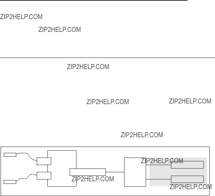
Chapter 5. Single RS/6000 SP and Single SP Switch Router
This section provides several sample configurations that are possible with a single RS/6000 SP and a single SP Switch Router. Sample configurations range from using the SP Switch Router as a conventional high performance router up to the connection of two SP partitions, allowing
5.1 Single SP Partition and Single SP Switch Router Adapter Card
In this configuration, a single SP Switch Router Adapter card is connected to a single SP partition and works as a conventional high performance router. See Figure 52 for details. Five sample configurations that are common in customer environments were tested:
1.SP Switch - Ethernet Connection
2.SP Switch - FDDI Connection
3.SP Switch - ATM Connection
4.SP Switch - FDDI Connection (distinct backbones)
5.SP Switch - FDDI Connection (ADSM environment)
Figure 52. One Card - One SP Partition Sample Configuration
5.1.1 SP Switch - Ethernet Connection
This scenario might be appropriate in customers??? environments where 100 Mbit Ethernet is the choice for the backbone network. Up to eight computers, Ethernet switches or Ethernet hubs can be connected directly to the SP Switch.
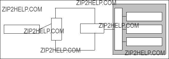
Configuration assumptions:
???The SP Switch Router Ethernet media card has been installed according to Section 4.1, ???Ethernet
???The SP Switch Router Adapter card has been installed according to Section 3.7,
???The SP Switch Router Adapter card and SP processor node Switch adapters are in the same IP subnet.
???ARP should be enabled on the SP Switch network to provide the most flexibility in assigning IP addresses (strongly recommended!).
???If ARP is disabled on the SP Switch network, the IP addresses assigned to the nodes must be determined by the Switch node numbers. Refer to
PSSP Planning, Volume 2, Control Workstation and Software Environment for details.
Configuration:
A RS/6000 model F50 with a PCI Ethernet adapter card is connected to port 1 of an Ethernet media card in the GRF 1600. The GRF 1600 SP Switch Router Adapter card is attached to the SP Switch of SP21, as shown in Figure 53 and Table 14 on page 159. The netmask for all interfaces is 255.255.255.0.
Figure 53. SP Switch - Ethernet Connection
Table 14 on page 159 shows the IP addresses used in our configuration.
158 IBM 9077 SP Switch Router: Get Connected to the SP Switch
Table 14. Configuration of SP Switch - Ethernet Connection
To successfully run this configuration, no routes need to be set on the SP Switch Router. The F50 and the processor nodes in SP21 require attention, though.
You should be able to ping the en0 interface on the F50:
(0)f50:/ 14$ ping 10.20.30.50
PING 10.20.30.50: (10.20.30.50): 56 data bytes
64 bytes from 10.20.30.50: icmp_seq=0 ttl=255 time=13 ms
64 bytes from 10.20.30.50: icmp_seq=1 ttl=255 time=0 ms
64 bytes from 10.20.30.50: icmp_seq=3 ttl=255 time=0 ms ^C
3 packets transmitted, 3 packets received, 0% packet loss
(0)f50:/ 15$
And you should also be able to ping the ge071 port of the GRF:
(0)f50:/ 15$ ping 10.20.30.1
PING 10.20.30.3: (10.20.30.1): 56 data bytes
64 bytes from 10.20.30.1: icmp_seq=0 ttl=255 time=0 ms
64 bytes from 10.20.30.1: icmp_seq=1 ttl=255 time=0 ms
64 bytes from 10.20.30.1: icmp_seq=2 ttl=255 time=0 ms ^C
3 packets transmitted, 3 packets received, 0% packet loss
(0)f50:/ 16$
To add the needed routing information, follow these steps:
1.On the F50, add the following route to the nodes in SP21: route add
Single RS/6000 SP and Single SP Switch Router 159

2. Check for correct routing entry:
3.On the nodes in SP21 that are supposed to communicate with the F50, add the following route:
route add
4. Check for correct routing entry:
The
5.Issue some ping commands to check the connection:
On the F50, ping the SP Switch interface of a chosen node in SP21:
160 IBM 9077 SP Switch Router: Get Connected to the SP Switch
(0)f50:/ 29$ ping 192.168.14.15
PING 192.168.14.15: (192.168.14.15): 56 data bytes
64 bytes from 192.168.14.15: icmp_seq=0 ttl=254 time=0 ms
64 bytes from 192.168.14.15: icmp_seq=1 ttl=254 time=0 ms
64 bytes from 192.168.14.15: icmp_seq=2 ttl=254 time=0 ms ^C
3 packets transmitted, 3 packets received, 0% packet loss
(0)f50:/ 30$
On the chosen nodes in SP21, ping the ATM interface of the F50:
root@sp21n01:/ ping f50
PING f50: (10.20.30.50): 56 data bytes
64 bytes from 10.20.30.50: icmp_seq=0 ttl=254 time=1 ms
64 bytes from 10.20.30.50: icmp_seq=1 ttl=254 time=0 ms
64 bytes from 10.20.30.50: icmp_seq=2 ttl=254 time=0 ms ^C
3 packets transmitted, 3 packets received, 0% packet loss
root@sp21n01:/
If these ping commands fail, check routing settings again. If everything is as it should be, try to ping the GRF Ethernet media card or the GRF SP Switch media card to find out which part is failing:
ping 192.168.14.4 (on chosen SP21 processor nodes)
ping 10.20.30.1 (on F50)
If any errors occur, check cabling, the configuration of SP Switch Router media cards (See Section 3.7,
Performance:
To get a rough overview of the data transfer rates that can be achieved in this scenario, we used ftp to conduct several file transfers of a 300 MB file from the F50 to the chosen nodes in SP21. We sent this file to /dev/null on the SP21 nodes to eliminate any hard disk influence on the receiver side:
Single RS/6000 SP and Single SP Switch Router 161

0)f50:/itso/space 32$ ftp 192.168.14.1 Connected to 192.168.14.1.
220 sp21n01 FTP server (Version 4.1 Tue Mar 17 14:00:13 CST 1998) ready. Name (192.168.14.1:root): root
331 Password required for root. Password:
230 User root logged in. ftp> bin
200 Type set to I.
ftp> put bos.obj.ssp.itso /dev/null 200 PORT command successful.
150 Opening data connection for /dev/null.
226 Transfer complete.
299878400 bytes sent in 31.95 seconds (9166 Kbytes/s) local: bos.obj.ssp.itso remote: /dev/null
ftp> quit 221 Goodbye.
(0)f50:/itso/space 33$
As you see in the screen shot, the F50???s 9.2 MB/s comes very close to the theoretical maximum throughput of about
On two SP21 nodes, we started ftp put commands to the F50, while the F50 was busy, putting data to other SP21 nodes, and observed an aggregate throughput over the Ethernet adapter of up to 15 MB/s, with more than 35% collision on the Ethernet and the F50 23% busy.
5.1.2 SP Switch - FDDI Connection
This is quite an easy scenario. It is used to connect workstations equipped with an FDDI interface card, FDDI hubs, and similar FDDI network devices to the SP Switch.
Configuration assumptions:
???The SP Switch Router FDDI media card was installed according to Section 4.4, ???FDDI Configuration??? on page 121, and works properly.
???The SP Switch Router Adapter card was installed according to Section 3.7,
???The SP Switch Router Adapter card and SP processor node Switch adapters are in the same IP subnet.
???ARP should be enabled on the SP Switch network to provide the most flexibility in assigning IP addresses (strongly recommended!).
162 IBM 9077 SP Switch Router: Get Connected to the SP Switch
???If ARP is disabled on the SP Switch network, the IP addresses assigned to the nodes must be determined by the Switch node numbers. Refer to
PSSP Planning, Volume 2, Control Workstation and Software Environment for details.
Note: The SP Switch Router Adapter card will not properly forward IP data to nodes assigned with an IP address that is in another subnet.
Configuration:
To establish this scenario, the FDDI interface of node 10 in SP21 was connected to the SP Switch Router FDDI media card, port A0. The SP Switch Router Adapter card is attached to the SP Switch of SP2, as shown in Figure 54 and Table 15. The netmask for all interfaces is 255.255.255.0.

 SP Switch

SP node
SP node
SP node
SP2
Figure 54. SP Switch - FDDI Connection
Table 15 shows the IP addresses used in our configuration.
Table 15. Configuration of an SP Switch - FDDI Connection
To successfully run this configuration, no routes need to be set on the SP Switch Router. Node 10 and the processor nodes in SP2 require attention,
Single RS/6000 SP and Single SP Switch Router 163
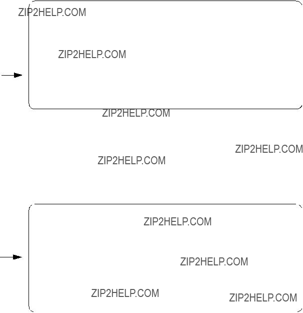
though. To add the needed routing information and check for proper work, follow these steps:
1.On node 10 in SP21, add the following route to the switch network of SP2: route add
2.Check for correct routing entry:
3.On the nodes in SP2 that are supposed to communicate with node 10 in SP21, add the following route:
route add
The
4.Check for correct routing entry:
5. On GRF 400 check /etc/grifconfig.conf for the following entry:
164 IBM 9077 SP Switch Router: Get Connected to the SP Switch

6.On the CWS of SP2 check if the SP Switch Router Adapter card is configured. See if the SP Switch Router Adapter card shows up green in perspectives or enter SDRGetObjects switch_responds. Use Eunfence if needed.
7.Issue some ping commands to check the connection:
On the chosen SP2 nodes, ping the FDDI interface of node 10 in SP21, for example:
root@sp2n09:/ ping 10.2.1.1
PING 10.2.1.1: (10.2.1.1): 56 data bytes
64 bytes from 10.2.1.1: icmp_seq=0 ttl=255 time=0 ms
64 bytes from 10.2.1.1: icmp_seq=1 ttl=255 time=0 ms ^C
2 packets transmitted, 2 packets received, 0% packet loss
On node 10 in SP21, ping the SP Switch interfaces of the chosen nodes in SP2, for example:
root@sp21n10:/ ping 192.168.13.9
PING 192.168.13.9: (192.168.13.9): 56 data bytes
64 bytes from 192.168.13.9: icmp_seq=0 ttl=255 time=0 ms
64 bytes from 192.168.13.9: icmp_seq=1 ttl=255 time=0 ms ^C
2 packets transmitted, 2 packets received, 0% packet loss
If these ping commands fail, check routing settings again. If everything is as it should be, try to ping the SP Switch Router FDDI media card or the SP Switch Router Adapter card to ascertain the failing part:
ping 192.168.13.4 (on chosen processor nodes in SP2)
ping 10.2.1.2 (on node 10 in SP21)
If any errors occur, check cabling, the configuration of the SP Switch Router media cards (See Section 3.7,
Performance:
To get a rough overview of the data transfer rates that can be achieved in such a scenario, we performed the following tests:
1.We obtained of tsock program (a derivative of the public domain ttcp program developed by T.C. Slattery, USNA, improved by Mike Muuss,
Single RS/6000 SP and Single SP Switch Router 165

BRL, and ported to AIX by Prof. Peter Haas, University of Stuttgart). tsock is a program that uses the UltraNet socket emulation library to perform numerous network exercises, among them to measure the pure network performance by eliminating any hard disk or processor load influence on the data transfer rate by sending data packets directly from memory to memory. We selected to send bursts of packets ranging from 1 byte to 50 kilobytes, as this might be a more realistic approach than just shifting large files around. In this scenario an average data transfer rate of about 12 MB/s was achieved which corresponds to the theoretical maximum data transfer rate of an FDDI connection (12.5 MB/s=100 Mb/s).
2.We used ftp to conduct several file transfers of a 300 MB file from different nodes in SP2. We sent this file to /dev/null on node 10 in SP21, to eliminate any hard disk influence on the receiver side:
root@sp2n09:/ ftp 10.2.1.1 Connected to 10.2.1.1.
220 sp21n10 FTP server (Version 4.1 Tue Mar 17 14:00:13 CST 1998) ready. Name (10.2.1.1:root):
331 Password required for root. Password:
230 User root logged in.
ftp> put bos.obj.ssp.itso /dev/null 200 PORT command successful.
150 Opening data connection for /dev/null.
226 Transfer complete.
299878400 bytes sent in 65.95 seconds (4441 Kbytes/s) local: bos.obj.ssp.itso remote: /dev/null
ftp> quit 221 Goodbye.
root@sp2n09:/space
As can be seen in the screen shot, the slow internal SCSI disks of the nodes in SP2 would not allow the transfer rate to exceed 4.5 MB/s. So we decided to start four ftp programs on four different nodes in SP2. We expected these four file transfers to sum up to an aggregate throughput of about 18 MB/s over the net. This would be beyond the throughput of an FDDI adapter, so we expected to reach the limits of the FDDI adapter, either in the GRF or on node 10 in SP21.
With this scenario, we measured an average transfer rate of about
166 IBM 9077 SP Switch Router: Get Connected to the SP Switch
5.1.3 SP Switch - ATM Connection
This scenario might be used quite often to attach a single computer with an ATM interface to the SP Switch of an SP system. This could, for example, be an RS/6000 model S70 acting as an ADSM server or as a database server in an SAP or BAAN environment. It could, as well, be a connection to another already existing ATM Switch.
Configuration assumptions:
???An SP Switch Router ATM media card has been installed according to Section 4.2, ???ATM
???An SP Switch Router Adapter card has been installed according to Section 3.7,
???The SP Switch Router Adapter card and SP processor node Switch adapters are in the same IP subnet.
???ARP should be enabled on the SP Switch network to provide the most flexibility in assigning IP Addresses (strongly recommended!).
???If ARP is disabled on the SP Switch network, the IP addresses assigned to the nodes must be determined by the Switch node numbers.
Note: The SP Switch Router Adapter card will not properly forward IP data to nodes assigned with an IP address that is in another subnet.
Configuration:
In this scenario, we chose an RS/6000 model F50 with a PCI ATM adapter card to be connected to an ATM port on an ATM
Single RS/6000 SP and Single SP Switch Router 167

SP21
Figure 55. SP Switch - ATM Connection
Table 16 shows the IP addresses used in our configuration.
Table 16. Configuration of SP Switch - ATM Connection
To successfully run this configuration, no routes need to be set on the SP Switch Router. The F50 and the processor nodes in SP21 require attention, though. To configure the ATM adapter in the F50, follow these steps:
1.On the F50, check that all the required software for ATM support is installed. There is no need for ATM LAN Emulation software support, though. If the ATM adapter is in the "available" state (check with lsdev
2.To avoid any pitfalls, set the signaling protocol for the ATM adapter to UNI3.0, as this is the default for the GRF and was probably not changed in the file /etc/gratm.conf on the GRF. You can check and look for a line where Signalling card= is not commented with a #.
It escapes our understanding why we had to bother with this, anyhow, as we could not set up and use SVC between the F50 and the GRF, because
168 IBM 9077 SP Switch Router: Get Connected to the SP Switch

of the lack of an ARP server; signaling protocols should only matter with SVCs and not with PVCs.
3.On the F50, use smitty chg_atm, select the ATM device and change the field SVC UNI Version from auto_detect to uni3.0:
4.Use smitty mkinetat to get to the Add an "ATM Network Interface" menu and fill in the blanks, as follows:
You may leave the Network Interface field blank, as at0 is the default interface on the device atm0, but you must change the Connection type from svc_s to pvc. As stated, we had no ARP server available, which is a prerequisite for any SVC type connection. Consider a PVC to be a permanent
Single RS/6000 SP and Single SP Switch Router 169

5. Have smitty carry out its work, exit smitty and then run smitty mkatmpvc:
In the optional PVC Description field, do not use blanks or underscores. In the VPI:VCI field, use the numbers you get from the PVC statement in the /etc/gratm.conf file on the GRF 1600. For your convenience, the relevant line is shown here again:
PVC ga0180 0/134 proto=ip traffic_shape=high_speed_high_quality
Note: Be very careful about the different naming conventions on the GRF and on AIX! Whereas the numbers are separated by a slash (/) in /etc/gratm.conf, you must use a colon (:) to separate them in SMIT!
Because we give the VPI:VCI numbers of the GRF ATM port and leave the field Automatically Discover Destination IP Address on its yes default, there is no need to fill in the Destination IP Address.
After smitty is done, you should be able to ping the at0 interface on the F50:
(0)f50:/ 14$ ping 10.1.2.3
PING 10.1.2.3: (10.1.2.3): 56 data bytes
64 bytes from 10.1.2.3: icmp_seq=0 ttl=255 time=13 ms
64 bytes from 10.1.2.3: icmp_seq=1 ttl=255 time=0 ms
64 bytes from 10.1.2.3: icmp_seq=3 ttl=255 time=0 ms ^C
3 packets transmitted, 3 packets received, 0% packet loss
(0)f50:/ 15$
You should also be able to ping the ga0180 port of the GRF:
170 IBM 9077 SP Switch Router: Get Connected to the SP Switch

(0)f50:/ 15$ ping 10.1.2.1
PING 10.1.2.1: (10.1.2.1): 56 data bytes
64 bytes from 10.1.2.1: icmp_seq=0 ttl=255 time=0 ms
64 bytes from 10.1.2.1: icmp_seq=1 ttl=255 time=0 ms
64 bytes from 10.1.2.1: icmp_seq=2 ttl=255 time=0 ms ^C
3 packets transmitted, 3 packets received, 0% packet loss
(0)f50:/ 16$
To add the needed routing information, follow these steps:
1.On the F50, add the following route to the nodes in SP21:
route add
2.Check for correct routing entry:
3.On the nodes in SP21 that are supposed to communicate with the F50, add the following route:
route add
4.Check for correct routing entry:
Single RS/6000 SP and Single SP Switch Router 171

The
5.Issue some ping commands to check the connection:
On the F50, ping the SP Switch interface of a chosen node in SP21:
(0)f50:/ 29$ ping 192.168.14.1
PING 192.168.14.1: (192.168.14.1): 56 data bytes
64 bytes from 192.168.14.1: icmp_seq=0 ttl=254 time=0 ms
64 bytes from 192.168.14.1: icmp_seq=1 ttl=254 time=0 ms
64 bytes from 192.168.14.1: icmp_seq=2 ttl=254 time=0 ms ^C
3 packets transmitted, 3 packets received, 0% packet loss
(0)f50:/ 30$
On the chosen nodes in SP21, ping the ATM interface of the F50:
root@sp21n01:/ ping f50
PING f50: (10.1.2.3): 56 data bytes
64 bytes from 10.1.2.3: icmp_seq=0 ttl=254 time=1 ms
64 bytes from 10.1.2.3: icmp_seq=1 ttl=254 time=0 ms
64 bytes from 10.1.2.3: icmp_seq=2 ttl=254 time=0 ms ^C
3 packets transmitted, 3 packets received, 0% packet loss
root@sp21n01:/
172 IBM 9077 SP Switch Router: Get Connected to the SP Switch
If these ping commands fail, check routing settings again. If everything is as it should be, try to ping the SP Switch Router ATM media card or the SP Switch Router Adapter card to which part is failing:
ping 192.168.14.4 (on chosen SP21 processor nodes)
ping 10.1.2.1 (on F50)
If any errors occur, check cabling, the configuration of SP Switch Router media cards (See Section 3.7,
Performance:
To get a rough overview of the data transfer rates that can be achieved in this scenario, the following tests were performed:
1.Again we used tsock to get the performance figures for a mix of packets ranging from 1 byte to 50 kilobytes. This time an average data transfer rate of about 13.5 MB/s was achieved, which corresponds well enough to the theoretical maximum data transfer rate of an ATM connection (17.5 MB/s=155 Mb/s).
2.We used ftp to conduct several file transfers of a 300 MB file from the F50 to the chosen nodes in SP21. We sent this file to /dev/null on the SP21 nodes to eliminate any hard disk influence on the receiver side:
(0)f50:/itso/space 32$ ftp 192.168.14.1 Connected to 192.168.14.1.
220 sp21n01 FTP server (Version 4.1 Tue Mar 17 14:00:13 CST 1998) ready. Name (192.168.14.1:root): root
331 Password required for root. Password:
230 User root logged in. ftp> bin
200 Type set to I.
ftp> put bos.obj.ssp.itso /dev/null 200 PORT command successful.
150 Opening data connection for /dev/null.
226 Transfer complete.
299878400 bytes sent in 31.05 seconds (9431 Kbytes/s) local: bos.obj.ssp.itso remote: /dev/null
ftp> quit 221 Goodbye.
(0)f50:/itso/space 33$
As you see in the screen shot, although the F50 has very fast disks attached, they still limit the file transfer rate to 9.4 MB/s. So we decided to start two ftp programs on the F50 in parallel. This way we could increase the throughput of the ATM adapter to about 16.5 MB/s, with the F50 being about 50% busy (all data again observed with the freeware tool monitor).
Single RS/6000 SP and Single SP Switch Router 173
An ATM adapter establishes a duplex connection to its partner, so the 16.5 MB/s write throughput should be accompanied by another 16.5 MB/s read throughput. To prove this, we started two ftp put commands from the same SP21 node. At the same time we started two ftp put commands an the F50 and observed an aggregate throughput over the ATM adapter of up to 28 MB/s, with the CPU of the SP node nearly 80% busy and the F50 100% busy.
5.1.4 SP Switch - FDDI Connection (Distinct FDDI Networks)
5.1.4.1 SP Switch - FDDI Connection without Bridging
This scenario is rather similar to the one described in Section 5.1.2, ???SP Switch - FDDI Connection??? on page 162 and is quite often met in customer environments. It might be used to connect four different FDDI backbones to a SP Switch, for instance in an ADSM environment.
Configuration assumptions:
???An SP Switch Router FDDI media card has been installed according to Section 4.4, ???FDDI Configuration??? on page 121 and works properly.
???An SP Switch Router Adapter card has been installed according to Section 3.7,
???The SP Switch Router Adapter card and SP processor node Switch adapters are in the same IP subnet.
???ARP should be enabled on the SP Switch network to provide the most flexibility in assigning IP Addresses (strongly recommended!).
???If ARP is disabled on the SP Switch network, the IP addresses assigned to the nodes must be determined by the Switch node numbers. Refer to
PSSP Planning, Volume 2, Control Workstation and Software Environment for details.
Note: The SP Switch Router Adapter card will not properly forward IP data to nodes assigned with an IP address that is in another subnet.
Configuration:
To establish this scenario, the FDDI interfaces of node 9, node 10, node 11 and node 12 in SP2 were connected to the SP Switch Router FDDI media card???s port B1, port A1, port B0 and port A0, respectively. (This "weird" connection had to be chosen because of limited cable length in our lab environment . Any other cabling might be used.). The SP Switch Router Adapter card is attached to the SP Switch of SP21, as shown in Figure 56 on
174 IBM 9077 SP Switch Router: Get Connected to the SP Switch

page 175 and Table 17 on page 175. The netmask for all interfaces is
Figure 56. SP Switch - FDDI Connection
Table 17 shows the IP addresses used in our configuration.
Table 17. Configuration of SP Switch - FDDI Connection
Single RS/6000 SP and Single SP Switch Router 175

To successfully run this configuration, all four ports of the SP Switch Router FDDI media card have to be assigned IP addresses in different subnets. Otherwise, only port A0 will be activated.
Note: Every port of the SP Switch Router FDDI media card has to be assigned to a different subnet when bridging is not configured (see Section 5.1.4.2, ???SP Switch - FDDI Connection with Bridging??? on page 179).
In this sample configuration no routes need to be set on the SP Switch Router. Node
1.On all four nodes in SP2 with an FDDI interface, add the route to the SP Switch network of SP21:
???On node 9 in SP2, add this route:
route add
???On node 10 in SP2, add this route:
route add
???On node 11in SP2, add this route:
route add
???On node 12 in SP2, add this route:
route add
2.Check for correct routing entries on all four nodes, for example:
176 IBM 9077 SP Switch Router: Get Connected to the SP Switch

3.On the nodes in SP21 that are supposed to communicate with the different FDDI backbones, add the necessary routes:
route add
route add
route add
route add
The
4. Check for correct routing entries, for example:
5. On GRF 1600, check /etc/grifconfig.conf for the following entries:
6.On GRF 1600, check whether all four port interfaces are created successfully. Use netstat
Single RS/6000 SP and Single SP Switch Router 177

7.On the CWS of SP21, check if the SP Switch Router Adapter card is configured. To perform this check, look if the SP Switch Router Adapter card shows up green in perspectives or enter SDRGetObjects switch_responds. Use Eunfence if needed.
8.Issue some ping commands to check the connection:
On the chosen SP21 nodes, ping all four FDDI interfaces of the nodes in SP2, for example:
root@sp21n01:/ ping 10.2.1.12
PING 10.2.1.12: (10.2.1.12): 56 data bytes
64 bytes from 10.2.1.12: icmp_seq=0 ttl=254 time=10 ms
64 bytes from 10.2.1.12: icmp_seq=1 ttl=254 time=1 ms ^C
2 packets transmitted, 2 packets received, 0% packet loss
On node
root@sp2n12:/ ping 192.168.14.1
PING 192.168.14.1: (192.168.14.1): 56 data bytes
64 bytes from 192.168.14.1: icmp_seq=0 ttl=254 time=1 ms
64 bytes from 192.168.14.1: icmp_seq=1 ttl=254 time=1 ms ^C
2 packets transmitted, 2 packets received, 0% packet loss
178 IBM 9077 SP Switch Router: Get Connected to the SP Switch
If these ping commands fail, check routing settings and IP address assignment again. If everything is as it should be, try to ping the GRF FDDI media card ports or the GRF SP Switch media card to find the failing part:
ping 10.2.1.15 (on node 12in SP2) ping 10.3.1.16 (on node 10 in SP2) ping 10.4.1.17 (on node 11 in SP2) ping 10.5.1.18 (on node 9 in SP2) ping 192.168.14.4 (on nodes in SP21)
If any errors occur, check cabling, the configuration of the SP Switch Router media cards (See Section 3.7,
Performance:
To get a rough overview of the data transfer rates that can be achieved in such a scenario, the following test was performed:
We used ftp to transfer several 300 MB large files from different nodes in SP21 to the four FDDI equipped nodes in SP2 and vice versa. We sent these files to /dev/null to eliminate any hard disk influence on the receiver side.
The slow internal SCSI disks in two of our four nodes in SP2 would not allow the transfer rate to exceed 4.5 MB/s. Both remaining nodes in SP2 contain faster SSA hard disks that allowed a transfer rate of 7.5 MB/s. Nevertheless, this would not be enough to exceed the FDDI bandwidth. So we decided to start several ftp programs on nodes in SP2 and SP21 to sum up the transfer rates.
With this scenario, we measured a cumulative transfer rate of up to 44 MB/s (observed with the freeware tool monitor) that is close to the maximum theoretical transfer rate of 4x12.5 MB/s=50 MB/s. Every node FDDI interface yielded an overall transfer rate of about 11 MB/s (sending and receiving). The limiting factor once again was the CPU on each of the four nodes that was not able to handle more data simultaneously (100% busy, as seen with monitor).
5.1.4.2 SP Switch - FDDI Connection with Bridging
This scenario corresponds closely to the one described in Section 5.1.4.1, ???SP Switch - FDDI Connection without Bridging??? on page 174. It might be used to transparently connect four physically separated FDDI backbones to one large LAN that is connected to the SP Switch.
Single RS/6000 SP and Single SP Switch Router 179
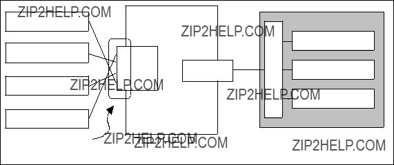
Configuration assumptions:
???An SP Switch Router FDDI media card has been installed according to Section 4.4, ???FDDI Configuration??? on page 121 and works properly.
???The SP Switch Router Adapter card has been installed according to Section 3.7,
???The SP Switch Router Adapter card and SP processor node Switch adapters are in the same IP subnet.
???ARP should be enabled on the SP Switch network to provide the most flexibility in assigning IP Addresses (strongly recommended!).
???If ARP is disabled on the SP Switch network, the IP addresses assigned to the nodes must be determined by the Switch node numbers.
Note: The SP Switch Router Adapter card will not properly forward IP data to nodes assigned with an IP address that is in another subnet.
Configuration:
To build this scenario, the FDDI interfaces of node 9, node 10, node 11 and node 12 in SP2 is connected to the SP Switch Router FDDI media card???s port B1, port A1, port B0 and port A0, respectively. The SP Switch Router Adapter card is attached to the SP Switch of SP21, as shown in Figure 57 and Table 18 on page 181. The netmask for all interfaces is 255.255.255.0.
Figure 57. SP Switch - FDDI Connection (Bridging)
180 IBM 9077 SP Switch Router: Get Connected to the SP Switch
Table 18 shows the IP addresses used in our configuration.
Table 18. Configuration of SP Switch - FDDI Connection (Bridging)
To successfully run this configuration, make sure that all four different FDDI backbones are logically located in one subnet. Otherwise, bridging does not work and routing has to be used. Nevertheless, the GRF simultaneously supports routing and bridging which means that an interface included in a bridge group is able to handle bridge
Note: All FDDI backbones have to be logically located in a single IP subnet for proper bridging. The GRF supports simultaneous routing and bridging over one interface.
In this sample configuration, no routes need to be set on the SP Switch Router. Node
1.Configure the bridge group on the GRF 1600.
???Define the bridge group:
Open the file /etc/bridged.conf with bredit or vi. If /etc/bridged.conf does not exist, a new file can be created or the /etc/bridged.conf.template can be renamed to /etc/bridged.conf. Enter the necessary bridge group information:
Single RS/6000 SP and Single SP Switch Router 181

bridge_group bg0 {
port gf000 gf001 gf002 gf003;
};
This is the simplest bridge definition that worked in our scenario. Many additional parameters can be set. See Section 4.6.9.3, ???Editing Utility ??? Bredit??? on page 146 for further details.
???Assign an IP address:
Open /etc/grifconfig.conf. Comment out all former FDDI interface definitions by inserting a # at the beginning of the respective lines. Define the new bridge group and assign an IP address that is in the same subnet as all four FDDI backbones:
Save /etc/grifconfig.conf. Issue grwrite
Note: According to GRF Configuration Guide 1.4,
2. Check for correct bridge interface creation on GRF 1600:
182 IBM 9077 SP Switch Router: Get Connected to the SP Switch
3.Add the route to the Switch network of SP21 on all four nodes of SP2 with an FDDI interface.
On node
route add
4. Check for correct routing entries on all four nodes, for example:
5.On the nodes in SP21 that are supposed to communicate with the four different FDDI backbones (that are logically only one LAN), add the necessary route:
route add
The
6. Check for correct routing entries, for example:
Single RS/6000 SP and Single SP Switch Router 183

7.On the CWS of SP21, check if the SP Switch Router Adapter card is configured. To perform this check, look if the SP Switch Router Adapter card shows up green in perspectives or enter SDRGetObjects switch_responds. Use Eunfence if needed.
8.Issue some ping commands to check the connection:
On the chosen SP21 nodes, ping all four FDDI interfaces of nodes in SP2, for example:
root@sp21n01:/ ping 10.10.1.9
PING 10.10.1.9: (10.10.1.9): 56 data bytes
64 bytes from 10.10.1.9: icmp_seq=0 ttl=254 time=2 ms
64 bytes from 10.10.1.9: icmp_seq=1 ttl=254 time=1 ms ^C
2 packets transmitted, 2 packets received, 0% packet loss
On node
root@sp2n12:/ ping 192.168.14.1
PING 192.168.14.1: (192.168.14.1): 56 data bytes
64 bytes from 192.168.14.1: icmp_seq=0 ttl=254 time=1 ms
64 bytes from 192.168.14.1: icmp_seq=1 ttl=254 time=1 ms ^C
2 packets transmitted, 2 packets received, 0% packet loss
If these ping commands fail, check routing settings, bridging settings and IP address assignment again. If everything is as it should be, try to ping the bridge group and the SP Switch Router media card to find the failing part:
ping 10.10.1.13 (on nodes
ping 192.168.14.4 (on nodes in SP21)
If any errors occur, check cabling, the configuration of SP the Switch Router media cards (See Section 3.7,
Performance:
To get a rough overview of the data transfer rates that can be achieved in such a bridging scenario, we again used ftp to transfer several 300 MB files from different nodes in SP21 to the four
184 IBM 9077 SP Switch Router: Get Connected to the SP Switch

vice versa. We sent these files to /dev/null to eliminate any hard disk influence on the receiver side.
The hardware requisites for this test are the same as described in Section 5.1.4.1, ???SP Switch - FDDI Connection without Bridging??? on page 174. The slow internal SCSI disks in two of our four nodes in SP2 would not allow the transfer rate to exceed 4.5 MB/s. Both remaining nodes in SP2 contain faster SSA hard disks that allow a transfer rate of 7.5 MB/s. Nevertheless, the overall achievable data transfer rate will not exceed the bandwidth of the FDDI connection. So we decided to start several ftp programs on nodes in SP2 and SP21 to sum up the transfer rates.
With this scenario, we again measured a cumulative transfer rate of up to 44 MB/s (observed with the freeware tool monitor) that is close to the maximum theoretical transfer rate of 4x12.5 MB/s=50 MB/s. Every node???s FDDI interface contributed an overall transfer rate of about 11 MB/s (sending and receiving). The limiting factor once again was the CPU on the four nodes in SP2 that was not able to handle more data simultaneously (100% busy, as seen with monitor). We could not find any significant influence of bridging on the measured data transfer rate.
5.1.5 SP Switch - FDDI Connection in an ADSM Environment
To get a view into a "real world" scenario and to check corresponding performance data, we established a simple ADSM environment. Four nodes in SP2 with FDDI interfaces stand for four FDDI backbones in a possible customer environment. These backbones send ADSM data via SP Switch Router to an ADSM server (see Figure 58). ADSM version 3.1.20 was installed.
Figure 58. SP Switch Router in an ADSM Environment
Single RS/6000 SP and Single SP Switch Router 185
Configuration assumptions:
???The SP Switch Router FDDI media card has been installed according to Section 4.4, ???FDDI Configuration??? on page 121, and works properly.
???The SP Switch Router Adapter card has been installed according to Section 3.7,
???The SP Switch Router Adapter card and SP processor node Switch adapters are in the same IP subnet.
???ARP should be enabled on the SP Switch network to provide the most flexibility in assigning IP Addresses (strongly recommended!).
???If ARP is disabled on the SP Switch network, the IP addresses assigned to the nodes must be determined by the switch node numbers.
Note: The SP Switch Router Adapter card will not properly forward IP data to nodes assigned with an IP address that is in another subnet.
???The ADSM server is installed on node1 in SP21; ADSM clients are installed on Nodes
Configuration:
The configuration of this scenario is exactly as described in Section 5.1.4.2, ???SP Switch - FDDI Connection with Bridging??? on page 179. Just one additional step has to be carried out, as follows:
1.Open /usr/lpp/adsm/bin/dsm.sys.
2.Change the parameter TCPServeraddress to the IP address of the Switch interface of node 1:
TCPServeraddress 192.168.14.1
Performance:
To get a rough overview of the data transfer rates that can be achieved during an ADSM backup session in our configuration, we started an incremental backup of a filesystem that contained a 300 MB file on nodes
We measured a transfer rate of up to 7 MB/s one ADSM client to the ADSM server. Starting another backup session on the other three nodes did not influence the transfer rate of the other nodes. Every node was able to transfer up to 7 MB/s independent of other nodes backup activity, summing up to 28 MB/s on the server side. This does not approach the maximum bandwidth of the SP Switch Router. Limiting factor in this scenario is the ability of the ADSM server to handle such data transfer rates (processor performance) and to write all data fast enough to storage media.
186 IBM 9077 SP Switch Router: Get Connected to the SP Switch

5.2 Single SP Partition and Multiple SP Switch Router Adapter Cards
It is frequently necessary to maintain the data transfer even when an SP Switch Router Adapter fails. This scenario describes how to setup a dual, not truly redundant, connection between SP Switch Router and SP Switch (see Figure 59) and how to recover from an adapter or cable failure.
5.2.1 Configuration of a Dual SP Switch Router Connection
Configuration assumptions:
???ARP should be enabled on the SP Switch network to provide the greatest flexibility in assigning IP addresses (strongly recommended!).
Figure 59. Connecting One SP Switch with Two SP Switch Router Adapter Cards
Table 19 shows the IP addresses used in our configuration.
Table 19. Configuration of a Dual SP Switch Router Connection
Configuration:
To establish this scenario, both SP Switch Router Adapter cards have to be configured correctly. We installed them according to Section 3.7,
Single RS/6000 SP and Single SP Switch Router 187
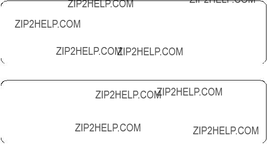
1.Each SP Switch Router Adapter card interface has to be in a different subnet.
2.Netmasks have to be used to create different subnets on the router side.
3.Logical subnetting is only required on the router. The SP switch sees a single network.
4.Each SP Switch Router Adapter card must have a unique IP address. An alias IP address cannot be used on two active cards on the same router system.
Note: Be careful that the subnet mask does not, in effect, create a single subnet. Assigning subnet masks of 255.255.255.0 and 255.255.255.128 to the SP Switch Router Adapter cards on the router side would set both SP Switch Router Adapter cards in the same subnet. This configuration does not work.
To check if both SP Switch Router Adapter cards work properly, do the following:
1.See if the SP Switch Router Adapter cards show up green in perspectives or use SDRGetObjects switch_responds. Use Eunfence if needed.
2.Issue a ping to both SP Switch Router Adapter cards from any node of SP21:
root@sp21n06:/ ping 192.168.14.4
PING 192.168.14.4: (192.168.14.4): 56 data bytes
64 bytes from 192.168.14.4: icmp_seq=0 ttl=255 time=0 ms
64 bytes from 192.168.14.4: icmp_seq=1 ttl=255 time=0 ms ^C
2 packets transmitted, 2 packets received, 0% packet loss
root@sp21n06:/ ping 192.168.14.129
PING 192.168.14.129: (192.168.14.129): 56 data bytes
64 bytes from 192.168.14.4: icmp_seq=0 ttl=255 time=0 ms
64 bytes from 192.168.14.4: icmp_seq=1 ttl=255 time=0 ms ^C
2 packets transmitted, 2 packets received, 0% packet loss
If any errors occur, check cabling, the configuration of the SP Switch Router Adapter cards (especially subnet mask setting), and also the network adapters in the nodes.
188 IBM 9077 SP Switch Router: Get Connected to the SP Switch
If the SP Switch Router Adapter cards work, the can both be used to route IP traffic from the SP Switch. Add the following routes to the SP nodes of SP21:
route add
zzz 192.168.14.4
to route outgoing traffic (coming from the SP node) via SP Switch Router Adapter card 1 and:
route add
zzz 192.168.14.129
to route outgoing traffic (coming from the SP node) via SP Switch Router Adapter card 2. xxx.xxx.xxx.xxx describes the destination network, yyy.yyy.yyy.yyy the corresponding netmask and zzz a proper MTU size for the chosen route.
Note: With Ascend Embedded/OS 1.4.6.4 (and lower versions) this configuration has an unpleasant side effect. When both SP Switch Router Adapter cards are unfenced, the maintenance Ethernet and the RS232 connection are down. No login to the router is possible and existing login sessions do not accept any command. The router itself works fine but no changes in router configuration can be made. A workaround is to fence one SP Switch Router Adapter card for maintenance work. This problem should be solved in Ascend Embedded/OS 1.4.8.
Nevertheless, the possibility to choose which SP Switch Router Adapter card should route outgoing traffic allows a certain degree ofload leveling. For best performance, you should divide your expected traffic in to two equal parts and set the corresponding routes.
So far, so good. But what happens when one SP Switch Router Adapter card fails and why is it possible at all, to ping 192.168.14.129, netmask 255.255.255.128, from node 6 in SP21 with IP address 192.168.14.1, netmask 255.255.255.0? Node 6 in SP21 is able to reach the IP address 192.168.14.129 because this address is in the same subnet as its own IP address. But the SP Switch Router Adapter card cannot reach node 6 in SP 21, because 192.168.14.1 is not in its subnet. So there is no way back and ping should not work. But it works fine.
The next sections throw light on both questions.
Single RS/6000 SP and Single SP Switch Router 189

5.2.2 Complex Configuration
In this section, we describe the setup of a complete scenario with a dual SP Switch Router connection, and explain why node 8 in SP21 in this setup is able to route IP traffic via IP address 192.168.14.129 (Figure 60 and Table 20 on page 191), although the way back apparently does not exist.
Figure 60. Configuration with Dual SP Switch Router - SP Switch Connection
Configuration assumptions:
???SP Switch Router Adapter cards were installed according to Section 3.7,
???ARP should be enabled on the SP Switch network to provide the most flexibility in assigning IP Addresses (strongly recommended!).
???The HIPPI connection is correctly installed and works (refer to Section 7.3, ???HIPPI Backbone Connection??? on page 227). We do not care about HIPPI connections in this chapter.
???All routes on the SP Switch Routers are assumed to be set correctly.
Table 20 on page 191 shows the IP addresses used in our configuration.
190 IBM 9077 SP Switch Router: Get Connected to the SP Switch

Table 20. Configuration of a Dual SP Switch Router - SP Switch Connection
Configuration:
For this scenario we chose the following route settings on our three test nodes in SP21 and on node 1 in SP2:
1. On node 1 in SP2, add the following route to the Switch network of SP21:
route add
192.168.13.4
The MTU size of 65280 is the optimum size for the HIPPI connection.
2. Check for correct routing entry:
Single RS/6000 SP and Single SP Switch Router 191
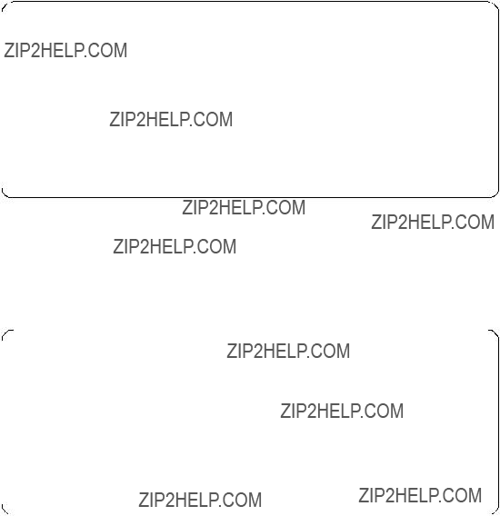
3. On node 6 in SP21, add the following route to the Switch network of SP2:
route add
192.168.14.4
The
4. Check for correct routing entry:
5. On node 8 in SP21, add the following route to the switch network of SP2:
route add
192.168.14.129
6. Check for correct routing entry:
7. On node 10 in SP21, add the following route to the switch network of SP2:
route add
192.168.14.129
192 IBM 9077 SP Switch Router: Get Connected to the SP Switch
8. Check for correct routing entry:
9. On GRF 1600, check /etc/grifconfig.conf for the following entries (or similar):
10.On the CWS of SP21 check if SP Switch Router Adapter cards are configured. See if both SP Switch Router Adapter cards show up green in perspectives or enter SDRGetObjects switch_responds. Use Eunfence if needed.
11.Issue some ping commands to check the connection:
On node 8, node 6 and node 10 of SP21, ping the switch interface of node 1 in SP2, for example:
root@sp21n06:/ ping 192.168.13.1
PING 192.168.13.1: (192.168.13.1): 56 data bytes
64 bytes from 192.168.13.1: icmp_seq=0 ttl=253 time=0 ms
64 bytes from 192.168.13.1: icmp_seq=1 ttl=253 time=0 ms ^C
2 packets transmitted, 2 packets received, 0% packet loss
Single RS/6000 SP and Single SP Switch Router 193

On node 1 in SP2, ping the SP Switch interfaces of the chosen nodes in SP21, for example:
root@sp2n01:/ ping 192.168.14.6
PING 192.168.14.6: (192.168.14.6): 56 data bytes
64 bytes from 192.168.14.6: icmp_seq=0 ttl=253 time=1 ms
64 bytes from 192.168.14.6: icmp_seq=1 ttl=253 time=1 ms ^C
2 packets transmitted, 2 packets received, 0% packet loss
If these ping commands fail, check routing settings again. If everything is as it should be, try to ping the SP Switch Router Adapter cards and check the HIPPI connection to find the failing part.
If any further errors occur, check cabling, the configuration of SP Switch Router media cards (See Section 3.7,
5.2.2.1 How the Traffic Flows
Why is it possible to ping 192.168.14.129, netmask 255.255.255.128 from node 6 in SP21 with IP address 192.168.14.6, netmask 255.255.255.0?
This question arose in Section 5.2.1, ???Configuration of a Dual SP Switch Router Connection??? on page 187. We treat this problem in a more general manner and look at our complex configuration (Figure 60 on page 190). What happens when our three chosen nodes in SP21 ping node 1 in SP2? The next three figures take a close look at the IP traffic flow. All three figures contain a simplified illustration of our complex configuration (Figure 60 on page 190). Figure 61 on page 195 shows the IP traffic flow when issuing the ping 192.168.13.1 on node 6 in SP21. All packets are first forwarded to the SP Switch Adapter card with IP address 192.168.14.4, according to the routing settings. From this SP Switch Adapter card all packets are forwarded via HIPPI connection to the only SP Switch Adapter card in GRF 400, which forwards the traffic to node 1 in SP2. The way back follows the same route. The SP Switch Adapter card with IP address 192.168.14.4 has no problem delivering IP packets to node 6 in the same subnet.
194 IBM 9077 SP Switch Router: Get Connected to the SP Switch
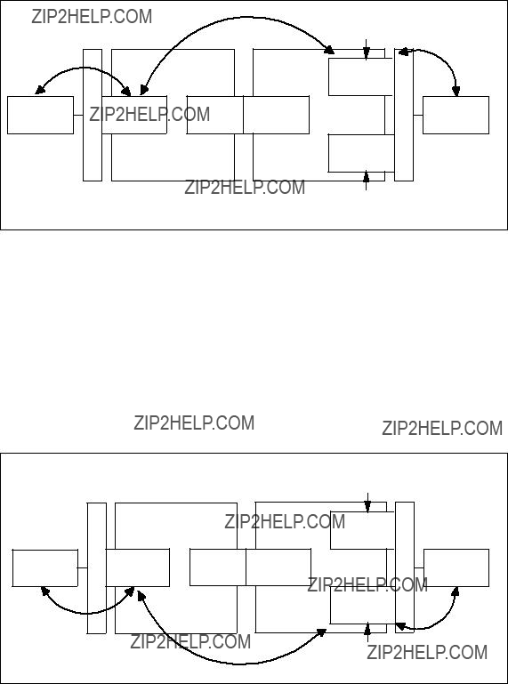
Figure 61. IP Traffic Flow When Issuing ping 192.168.13.1 on Node 6
Figure 63 on page 196 shows the IP traffic flow when issuing the ping 192.168.13.1 on node 10 in SP21. All packets are first forwarded to the SP Switch Adapter card with IP address 192.168.14.129 corresponding to the routing settings. From this SP Switch Adapter card all packets are forwarded via HIPPI connection to the only SP Switch Adapter card in GRF 400, which forwards the traffic to node 1 in SP2. The way back follows the same route. The SP Switch Adapter card with IP address 192.168.14.129 has no problem delivering IP packets to node 10 that is in the same subnet.
Figure 62. IP Traffic Flow When Issuing ping 192.168.13.1 on Node 10
Single RS/6000 SP and Single SP Switch Router 195
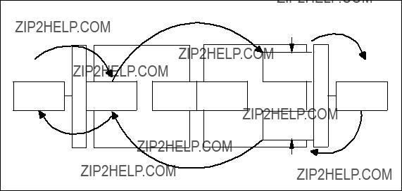
Figure 63 shows the IP traffic flow when issuing ping 192.168.13.1 on node 8 in SP21. All packets are first forwarded to the SP Switch Adapter card with IP address 192.168.14.129 corresponding to the routing settings. From this SP Switch Adapter card all packets are forwarded via HIPPI connection to the only SP Switch Adapter card in GRF 400, which forwards the traffic to node 1 in SP2. The way back follows first the same route. The internal logic of the GRF 1600 determines that the SP Switch Adapter card with IP address 192.168.14.129 is not able to deliver received packets back to node 8 because their IP address is in another subnet. So GRF 1600 uses the SP Switch Adapter card with IP address 192.168.14.4 to forward the IP traffic to node 8, because this is the only way to IP address 192.168.14.8.
Figure 63. IP Traffic Flow When Issuing ping 192.168.13.1 on Node 8
5.2.3 Recovery Procedure for an SP Switch Adapter Card Failure
What happens, when one of the SP Switch Adapter cards fails? A detailed look at Figure 61, Figure 62 and Figure 63 gives an answer:
1.When the SP Switch Adapter card with IP address 192.168.14.4 fails, neither node 6 nor node 8 can communicate with node 1 in SP2. Node 10 is not interrupted.
2.When the SP Switch Adapter card with IP address 192.168.14.129 fails, neither node 10 nor node 8 can communicate with node 1 in SP2. Node 6 is not interrupted.
Note: Node 8 is always affected, independent of the failing SP Switch Adapter card. Try to avoid routing settings that need both SP Switch Adapter cards for proper functioning.
196 IBM 9077 SP Switch Router: Get Connected to the SP Switch

To recover from a failing SP Switch Adapter card, you have to define an alias IP address for the surviving card. Follow these steps when gt030 fails:
1.Login as root to the SP Switch Router.
2.Remove the interface of gt030 from active status: ifconfig gt030 delete
3.Assign the alias IP address to gt050:
ifconfig gt050 alias 192.168.14.4 netmask 255.255.255.128
Follow these steps, when gt050 fails:
1.Login as root to SP Switch Router.
2.Remove the interface of gt050 from active status: ifconfig gt050 delete
3.Assign the alias IP address to gt030:
ifconfig gt030 alias 192.168.14.129 netmask 255.255.255.128
After setting the alias address, verify with the grarp command that the arp table shows the correct IP addresses and corresponding physical SP Switch addresses, for example:
grf16:/root grarp 192.168.14.129
???(0): 192.168.14.129 at 0:0:0:0:0:f
???(0): 192.168.14.4 at 0:0:0:0:0:f
Both IP addresses have to show the same physical SP Switch address.
5.3 Multiple SP Partition and Multiple SP Switch Router Adapter Cards
A partitioned RS/6000 SP has some advantages: It is possible to separate production and development systems that is, test new software in one partition without crashing the entire system when one partition crashes. Last but not least, several partitions can run several software versions that are incompatible with each other in one partition.
But one large disadvantage remains: There is no
Single RS/6000 SP and Single SP Switch Router 197

Configuration assumptions:
???The RS/6000 SP is partitioned in to two or more partitions (two partitions for this scenario).
Note: Be careful when choosing the partition layout. In every partition, a free Switch chip port to connect the SP Switch Router Adapter card is necessary.
??? Every partition establishes a single subnet.
Note: Be careful when subnetting your SP partitions. Although not necessary when you simply partition your SP, it is required that every partition in effect form in a single subnet to establish a connection via an SP Switch Router. All other subnetting does not work.
???ARP should be enabled on the SP Switch network to provide the greatest flexibility in assigning IP addresses (strongly recommended!).
SP Switch
Figure 64.
198 IBM 9077 SP Switch Router: Get Connected to the SP Switch

Table 21 shows the IP addresses used in our configuration.
Table 21. Configuration of a Partition - Partition Connection
Configuration:
For this scenario, the following routes have to be set:
1.On node 11, node 12 and node 15 in SP2, add the following route to the switch network of partition 1 of SP2:
route add
192.168.13.129
The MTU size of 65520 is the optimum size for the SP Switch network.
2. Check for correct routing entries, for example:
3.On all nodes in partition 1 in SP2, add the following route to the switch network of partition 2 in SP2:
route add
192.168.13.4
Single RS/6000 SP and Single SP Switch Router 199

The
4. Check for correct routing entry:
5.On GRF 400, check /etc/grifconfig.conf for the following entry (or one similar):
gt020 192.168.13.129 255.255.255.128
gt030 192.168.13.4 255.255.255.128
6.On the CWS of SP2, check if SP Switch Router Adapter cards are configured. See if both SP Switch Router Adapter cards show up green in perspectives or enter SDRGetObjects switch_responds. Use Eunfence if needed.
7.Issue some ping commands to check the connection:
On node 11, node 12 and node 15 of SP2, ping the SP Switch interface of any node in partition 1 in SP2, for example:
root@sp2n11:/ ping 192.168.13.1
PING 192.168.13.1: (192.168.13.1): 56 data bytes
64 bytes from 192.168.13.1: icmp_seq=0 ttl=254 time=0 ms
64 bytes from 192.168.13.1: icmp_seq=1 ttl=254 time=0 ms ^C
2 packets transmitted, 2 packets received, 0% packet loss
On any node in partition 1 in SP2, ping the SP Switch interfaces of any node in partition 2 in SP2, for example:
200 IBM 9077 SP Switch Router: Get Connected to the SP Switch

root@sp2n01:/ ping 192.168.13.132
PING 192.168.13.132: (192.168.13.132): 56 data bytes
64 bytes from 192.168.13.132: icmp_seq=0 ttl=254 time=1 ms
64 bytes from 192.168.13.132: icmp_seq=1 ttl=254 time=1 ms ^C
2 packets transmitted, 2 packets received, 0% packet loss
If these ping commands fail, check routing settings again. If everything is as it should be try to ping the SP Switch Router Adapter cards to find the failing part:
ping 192.168.13.4 (on nodes in partition 1) ping 192.168.13.129 (on nodes in partition 2)
If any further errors occur, check cabling, the configuration of SP Switch Router media cards (See Section 3.7,
Performance:
We did no performance measurement for this scenario. This setup is rather similar to the one described in Section 6.1, ???RS/6000 SP Switch - RS/6000 SP Switch Connection??? on page 203. There is no good reason why these scenarios should achieve a different data transfer rate. So we expect a data transfer rate of about 80 MB/s between the partitions, as before.
Single RS/6000 SP and Single SP Switch Router 201
202 IBM 9077 SP Switch Router: Get Connected to the SP Switch
Chapter 6. Multiple RS/6000 SPs and One SP Switch Router
In this configuration, two RS/6000 SP systems are connected to a single SP Switch Router. This enables both SPs to communicate deploying the SP Switch data transfer rate and/or to share other network resources. See Figure 65 for an overview.
Figure 65. Two RS/6000 SPs Connected to GRF 1600
6.1 RS/6000 SP Switch - RS/6000 SP Switch Connection
This scenario corresponds to Figure 65. It might be used to connect two RS/6000 SPs to exploit the SP Switch data transfer rate. Because of the switch cable length limit of 20m, this scenario is only applicable when both SPs have a maximum distance of 40m. In all other cases you will need two routers and a corresponding high speed connection (refer to Chapter 7, ???Multiple RS/6000 SPs and Multiple GRFs??? on page 209).
Configuration assumptions:
???Both SP Switch Router Adapter cards have been installed according to Section 3.7,
Note: When configuring the second SP Switch Router Adapter card, ensure that both Control Workstations are defined as SNMP managers in
/etc/snmpd.conf on the GRF 1600. To check, open this file and look for a stanza similar to the following:
MANAGER 192.168.4.137
SEND ALL TRAPS
TO PORT 162
WITH COMMUNITY spenmgmt
This stanza is needed twice, one for each CWS. Otherwise, the SP Switch Router Adapter card will hang in state loading. Additionally, when you assign an IP address to the second SP Switch Router Adapter card using SMIT, ensure that this IP address can be resolved by name service, be it DNS or /etc/hosts based. Otherwise the card cannot be unfenced.
???The SP Switch Router Adapter card and SP processor node switch adapters are in the same IP subnet on both SPs.
???ARP should be enabled on the SP Switch networks to provide the most flexibility in assigning IP addresses (strongly recommended!).
???If ARP is disabled on the SP Switch network, the IP addresses assigned to the nodes must be determined by the switch node numbers.
Note: The SP Switch Router Adapter card will not properly forward IP data to nodes assigned with an IP address that is in another subnet.
Configuration:
To establish this scenario, on the GRF 1600, an SP Switch Router Adapter card (slot 4) is attached to the SP Switch of SP2, a second card (slot 3) to the SP Switch of SP21, as shown in Table 22 and Figure 65 on page 203. The netmask for all interfaces is 255.255.255.0.
Table 22. Configuration of SP Switch - SP Switch Connection
To successfully run this configuration, no routes need to be set on the SP Switch Router. Just set the corresponding routes on all nodes of SP2 and SP21:
1. On nodes in SP21, add the following route to the switch network of SP2:
204 IBM 9077 SP Switch Router: Get Connected to the SP Switch

route add
192.168.14.4
2. Check for correct routing entry:
3. On nodes in SP2, add the following route to the switch network of SP21:
route add
192.168.13.16
The
4. Check for correct routing entry:
5. On GRF 1600, check /etc/grifconfig.conf for the following entry:
6.On the CWS of SP2 and on the CWS of SP21, check if SP Switch Router Adapter cards are configured. Check if the SP Switch Router Adapter
Multiple RS/6000 SPs and One SP Switch Router 205

cards shows up green in perspectives or enter SDRGetObjects
switch_responds. Use Eunfence if needed.
7.Issue some ping commands to check the connection:
On the SP2 nodes, ping the SP Switch interface of any node in SP21:
root@sp2n01:/ ping 192.168.14.1
PING 192.168.14.1: (192.168.14.1): 56 data bytes
64 bytes from 192.168.14.1: icmp_seq=0 ttl=254 time=1 ms
64 bytes from 192.168.14.1: icmp_seq=1 ttl=254 time=1 ms ^C
2 packets transmitted, 2 packets received, 0% packet loss
On the SP21 nodes, ping the SP Switch interface of any node in SP2:
root@sp21n01:/ ping 192.168.13.1
PING 192.168.13.1: (192.168.13.1): 56 data bytes
64 bytes from 192.168.13.1: icmp_seq=0 ttl=254 time=1 ms
64 bytes from 192.168.13.1: icmp_seq=1 ttl=254 time=1 ms ^C
2 packets transmitted, 2 packets received, 0% packet loss
If these ping commands fail, check routing settings again. If everything is as it should be, try to ping both SP Switch Adapter cards to find the failing part:
ping 192.168.13.16 (on SP2 nodes) ping 192.168.14.4 (on SP21 nodes)
If any errors occur, check cabling, the configuration of the SP Switch Router cards (see Section 3.7,
Performance:
To get a rough overview of the data transfer rates that can be achieved between the SPs, we again used ftp to transfer several 300MB files from different nodes in SP2 to several nodes in SP21. We sent these files to /dev/null to eliminate any hard disk influence on the receiver side.
The requisites for this test are the same as described in Section 5.1.4.1, ???SP Switch - FDDI Connection without Bridging??? on page 174. We started ftp transfers on all available nodes of SP2 and on some nodes of SP21.
206 IBM 9077 SP Switch Router: Get Connected to the SP Switch
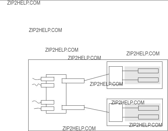
With this scenario and without further tuning (refer to Appendix A, ???Laboratory Hardware and Software Configuration??? on page 233 for actual no parameters), we measured a stable cumulative transfer rate of up to 83 MB/s (observed with the freeware tool monitor). This was the maximum transfer rate achievable in our environment. We are confident that further tuning and faster nodes can achieve higher transfer rates up to the maximum of GRFs crosspoint switch which is 100 MB/s.
6.2 Sharing Network Resources
This scenario is a combination of the scenario described in Section 6.1, ???RS/6000 SP Switch - RS/6000 SP Switch Connection??? on page 203 and one or more of the scenarios described in Section 5.1.1, ???SP Switch - Ethernet Connection??? on page 157, Section 5.1.2, ???SP Switch - FDDI Connection??? on page 162, Section 5.1.3, ???SP Switch - ATM Connection??? on page 167 and Section 5.1.4, ???SP Switch - FDDI Connection (Distinct FDDI Networks)??? on page 174. In an extended network, resources are always rare. This scenario might help to share these resources between several SPs and at the same time to connect these SPs with a high speed connection (see Figure 66).
Figure 66. Sharing Network Resources between Two SPs
To establish this scenario, simply follow the steps in Section 6.1, ???RS/6000 SP Switch - RS/6000 SP Switch Connection??? on page 203 first. If all tests are successful, set up the connection from each SP and its nodes to the required network resources. Follow the steps given in Section 5.1, ???Single SP Partition and Single SP Switch Router Adapter Card??? on page 157. We found no
Multiple RS/6000 SPs and One SP Switch Router 207
interference between data transfers from each SP to different SP Switch Router Adapter media cards except the one caused by limited bandwidth of the different network types (FDDI, ATM).
208 IBM 9077 SP Switch Router: Get Connected to the SP Switch

Chapter 7. Multiple RS/6000 SPs and Multiple GRFs
In this section, sample configurations with two SP systems connected with two SP Switch Routers are presented. The routers, in turn, are connected by any kind of high speed network supported by the GRF. Preferable selections are dedicated high performance networks such as FDDI, ATM or HIPPI. Figure 67 on page 209 will help to understand the setup.
This scenario might be suitable to connect two SP systems that are installed in different locations - such as different buildings - and cannot be connected directly with one SP Switch Router, as in Chapter 6, ???Multiple RS/6000 SPs and One SP Switch Router??? on page 203.
Figure 67. Connection of Two SPs with Two SP Switch Routers
7.1 ATM
As introduced in Section 4.2, ???ATM
Remember, the GRF is a router and as such expects every port on any media card to be in a different network (logical or physical), otherwise there would be no need to route. This means that without further work the two ports of the ATM media card cannot be used simultaneously to connect two GRFs with a
fast network. (The spare second port might be in use for example for a connection to an ATM attached device that needs a fast path to the SP Switch network).
To make use of both ports, four possible solutions come to mind:
1.Break up your already existing network topology (nodes of the SP) and create different subnets, which in turn can be routed over the different ATM subnets on the two ports.
We do not expect that any customer will do this, but the solution is mentioned here for the sake of completeness.
2.Configure the two ATM ports on different networks and route one half of the nodes over the first ATM port and route the other half over the second ATM port. It will be a pain, though, to maintain the different routes, so solution 4. below might be considered.
3.Configure the two ATM ports for transparent bridging and use the two ports simultaneously with just one IP address assigned to them. This solution sounds promising and will be covered in Section 7.1.2, ???ATM
4.Configure dynamic routing and use the open shortest path first (OSPF) protocol to use the two ATM ports equivalently. They have to be in different subnets, but gated will take care of that. Configuring gated is said to be a
7.1.1 ATM
Now, let us consider the setup of the
Configuration assumptions:
???The SP Switch Router ATM media card has been installed according to Section 4.2, ???ATM
???The SP Switch Router Adapter card has been installed according to Section 3.7,
???The SP Switch Router Adapter card and SP processor node Switch adapters are in the same IP subnet on the respective SP.
???ARP should be enabled on the SP Switch network to provide the most flexibility in assigning IP addresses (strongly recommended!).
210 IBM 9077 SP Switch Router: Get Connected to the SP Switch
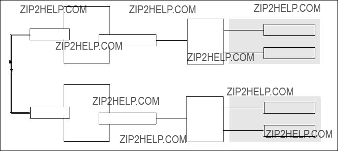
???If ARP is disabled on the SP Switch network, the IP addresses assigned to the nodes must be determined by the switch node numbers.
Note: The SP Switch Router Adapter card will not properly forward IP data to nodes assigned with an IP address that is in another subnet.
Configuration:
In this scenario, we have the SP Switch of SP21 connected to the GRF 1600. The GRF 1600 has its ATM
Figure 68. SP Switch - ATM - SP Switch Connection
Table 23 on page 212 shows the IP addresses used in our configuration.
Multiple RS/6000 SPs and Multiple GRFs 211
Table 23. Configuration of SP Switch - ATM - SP Switch
To successfully run this configuration, a route to the distant SP Switch network has to be set on every SP Switch Router. On the nodes of SP2 and SP21, respectively, routes to the nodes of the distant SP have to be set.
The media card on the GRF routers should already be up and running (according to Section 3.7,
??? On GRF 1600 (ATM card in slot 1, SP Switch card in slot 3):
1.The file /etc/gratm.conf needs the configuration statements for the port used:
Traffic_Shape name=high_speed_high_quality \ peak=155000 sustain=155000 burst=2048 qos=high
Interface ga010 traffic_shape=high_speed_high_quality
PVC ga010 0/132 proto=ip traffic_shape=high_speed_high_quality
2. The file /etc/grifconfig.conf has the following entries:
This will set the correct route to the other SP Switch network over the ATM interface automatically; of course, this route could also be set manually every time the GRF is rebooted.
4.The SP Switch Router Adapter card is connected to the SP Switch and configured, too. Check with SDRGetObjects switch_responds on the CWS and use Eunfence if needed.
???On GRF 400 (ATM card in slot 2, SP Switch card in slot 1):
212 IBM 9077 SP Switch Router: Get Connected to the SP Switch
1.The file /etc/gratm.conf needs the configuration statements for the port used:
Traffic_Shape name=high_speed_high_quality \ peak=155000 sustain=155000 burst=2048 qos=high
Interface ga020 traffic_shape=high_speed_high_quality
PVC ga020 0/132 proto=ip traffic_shape=high_speed_high_quality
2. The file /etc/grifconfig.conf has the following entries:
3. The file /etc/grroute.conf has the following line:
192.168.14.0 255.255.255.0 10.1.1.1
This will set the correct route to the other SP Switch network over the ATM interface automatically; of course, this route could also be set manually every time the GRF is rebooted.
4.The SP Switch Router Adapter card is connected to the SP Switch and configured, too. Check with SDRGetObjects switch_responds on the CWS and use Eunfence if needed.
5.On the nodes in SP21, the following route needs to be set:
route add
192.168.14.4
6. On the nodes in SP2, the following route needs to be set:
route add
192.168.13.4
The above command should be given in one line, the \ is to show where the line break occurred during printing. To avoid any pitfalls, set the MTU size explicitly to the size of the ATM adapter.
Hint: You must not use SMIT to set this route and put it into the ODM. The SP Switch is not operational at the time, this route would be set during boot time. Therefore this route would be put onto another, already available network interface, for example the Control Ethernet, and this is definitely not what you want to happen.
Use a separate /etc/rc.routes shell script that is run only after an Estart or an Eunfence was issued, or use some other mechanisms to have this route set only after the css0 interfaces on the SP nodes are up and running.
Setup is done now, and every node in SP2 should now be able to ping every node in SP21 and vice versa.
5. Check for correct routing entries on all nodes in SP21:
Multiple RS/6000 SPs and Multiple GRFs 213

6. Check for correct routing entries on all nodes in SP2:
7.Issue some ping commands to check the connection:
On the SP21 nodes, ping the SP Switch interface of nodes in SP; on nodes in SP2, ping the SP Switch interface of nodes in SP21.
If these ping commands fail, check routing settings again. If everything is as it should be, try to ping the SP Switch Router ATM media card or the SP Switch Router Adapter card to find the failing part:
ping 192.168.14.4 (on SP21 processor nodes)
ping 192.168.13.4 (on SP2 processor nodes)
ping 10.1.1.1 and ping 10.1.1.2 (on both GRF 400 and GRF 1600)
If any errors occur, check cabling, the configuration of the SP Switch Router media cards (see Section 3.7,
214 IBM 9077 SP Switch Router: Get Connected to the SP Switch
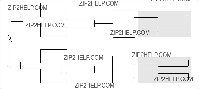
Performance:
To get a rough overview of the data transfer rates that can be achieved in this scenario, the following test was performed:
1.We used ftp to conduct several file transfers of a 300 MB file from the nodes in SP2 to one chosen node in SP21, and at the same time used ftp to conduct several file transfers of a 300 MB file from the nodes in SP21 to a chosen node in SP2. We sent the files to /dev/null on the receiving node to eliminate any hard disk influence.
We saw up to about 14.5 MB/s with just one side sending data; with all nodes sending and receiving, we achieved an duplex throughput of about 24 MB/s on the ATM port.
So it just might turn out that one 155 Mbit ATM port is not enough for a performance connection between two SP systems.
7.1.2 ATM
This setup is basically the same as using just one port of the ATM card, as described in Section 7.1.1, ???ATM
Figure 69. SP Switch - ATM Bridged - SP Switch Connection
Multiple RS/6000 SPs and Multiple GRFs 215

Table 24 shows the IP addresses used in our configuration.
Table 24. Configuration of SP Switch - ATM Bridged - SP Switch
Basically, the two ports are managed by a specific daemon and packets are sent over the participating ports depending on parameters in the configuration file /etc/bridged.conf.
A "wrapped" version of vi, called bredit, is available on the GRF router, and you should use it to create or edit the configuration file by running the command bredit.
First, we look at the GRF 1600:
1.The following screen shot gives you the minimum required data to be put into /etc/bridged.conf:
#bredit
#bridge_group bg0 {
#port gf000 gf001 gf002 gf003;
#};
bridge_group bg1 (
port ga010 ga0180;
};
:wq!
/tmp/bridged.conf.6117: 7 lines, 101 characters.
Update /etc/bridged.conf with these changes? [y/n] [n] y Parsed file "/tmp/bridged.conf.6117" successfully. Changes committed.
Use grwrite(8) to make the changes permanent. Signal bridged to effect changes now? [y/n] [n] n
Use ???brsig hup??? to force bridged(8) to
#
Remarks: The data from bridge_group bg0 (used in Section 5.1.4.2, ???SP Switch - FDDI Connection with Bridging??? on page 179) was commented out for our convenience. Up to 16 bridge groups are allowed on a GRF
216 IBM 9077 SP Switch Router: Get Connected to the SP Switch
Router, so there was no technical reason for it. The :wq! in the screen shot is there to remind you how to end editing of the file, and we give an n (no) as answer to the last question, as the ATM ports are already in use and therefore cannot be modified. So we need to reboot the GRF, and this takes care of the relevant settings anyway. See Section 4.6.9.3, ???Editing Utility ??? Bredit??? on page 146 for more information.
2. The following changes need to be applied to /etc/grifconfig.conf:
Remarks: The data for the ga010 and ga0180 interface needs to be commented out and the line for bg1 bridge_group needs to be put in. The netmask entry is mandatory for bridge_group entries.
3. Finally, bridging requires these entries in the /etc/gratm.conf file:
Traffic_Shape name=high_speed_high_quality \
peak=155000 sustain=155000 burst=2048 qos=high
This entry remains the same as in the basic configuration:
Interface ga010 traffic_shape=high_speed_high_quality \
bridge_method=llc_encapsulated
Interface ga0180 traffic_shape=high_speed_high_quality \
bridge_method=llc_encapsulated
These two lines were changed from the basic configuration!
PVC ga010 0/132 proto=llc,bridging
PVC ga0180 0/134 proto=llc,bridging
Because the GRF supports inverse ATM ARP (InATMARP), there is no need to put any entries in /etc/grarp.conf.
The file /etc/grroute.conf also remains unchanged:
192.168.13.0 255.255.255.0 10.1.1.2
If there is no such entry in /etc/grroute.conf, the following command must be run on GRF 1600:
route add
Multiple RS/6000 SPs and Multiple GRFs 217

Now it is time to look at the GRF 400:
1.The following screen shot gives you the minimum required data to be put into /etc/bridged.conf:
# bredit
Could not find default config file ???/etc/bridged.conf???. This seems to be the first time bridged is being configured.
Do you want to use the template configuration file ? [y/n] [n] y
G
bridge_group bg1 (
port ga020 ga0280;
};
:wq!
/tmp/bridged.conf.2371: 7 lines, 101 characters.
Update /etc/bridged.conf with these changes? [y/n] [n] y Parsed file "/tmp/bridged.conf.2371" successfully. Changes committed.
Use grwrite(8) to make the changes permanent. Signal bridged to effect changes now? [y/n] [n] n
Use ???brsig hup??? to force bridged(8) to
#
Remarks: On the GRF 400, bridging was never defined before, so we have to create /etc/bridged.conf from a template. Just jump to the end of the template and type in the data. The :wq! is there to remind you how to end editing of the file. We give an n (no) as answer to the last question, as the ATM ports are already in use and therefore cannot be modified. So we need to reboot the GRF, and takes care of the relevant settings anyway.
2. The following changes need to be applied to /etc/grifconfig.conf:
Remarks: The data for the ga020 and ga0280 interface needs to be commented out and the line for bg1 bridge_group needs to be put in. The netmask entry is mandatory for bridge_group entries.
3. Finally, bridging requires four entries in the /etc/gratm.conf file:
Traffic_Shape name=high_speed_high_quality \
peak=155000 sustain=155000 burst=2048 qos=high
This following entries remains the same as is the basic configuration:
Interface ga020 traffic_shape=high_speed_high_quality \
bridge_method=llc_encapsulated
Interface ga0280 traffic_shape=high_speed_high_quality \
bridge_method=llc_encapsulated
218 IBM 9077 SP Switch Router: Get Connected to the SP Switch

This two lines were changed from the basic configuration!
PVC ga020 0/132 proto=llc,bridging
PVC ga0280 0/134 proto=llc,bridging
Because the GRF supports InATMARP, there is no need to have any entries in /etc/grarp.conf.
The file /etc/grroute.conf also remains unchanged:
192.168.14.0 255.255.255.0 10.1.1.1
If there is no such entry in /etc/grroute.conf, the following command must be run on GRF 400 after every reboot:
route add
We chose to have the IP address of the bg1 "interface" the same as the respective ATM port0 interface before, so there was no need to change any routes on the SP2 or SP21 nodes.
Check for correct routing entry on all nodes in SP21:
Check for correct routing entry on all nodes in SP2:
Multiple RS/6000 SPs and Multiple GRFs 219

Issue some ping commands to check the connection:
On the SP21 nodes, ping the SP Switch interface of nodes in SP2, on nodes in SP2 ping the SP Switch interface of nodes in SP21.
If these ping commands fail, check routing settings again. If everything is as it should be, try to ping the SP Switch Router ATM media card or the SP Switch Router Adapter card, to find the failing part:
ping 192.168.14.4 (on SP21 processor nodes)
ping 192.168.13.4 (on SP2 processor nodes)
ping 10.1.1.1 and ping 10.1.1.2 (on both GRF 400 and GRF 1600)
If any errors occur, check cabling, the configuration of the SP Switch Router media cards (see Section 3.7,
Performance:
To get a rough overview of the data transfer rates that can be achieved in this scenario, the following test was performed:
1.We used ftp to conduct several file transfers of a 300 MB file from the nodes in SP2 to one chosen node in SP21, and at the same time used ftp to conduct several file transfers of a 300 MB file from the nodes in SP21 to a chosen node in SP2. We sent the files to /dev/null on the receiving nodes to eliminate any hard disk influence:
We saw up to about 14.5 MB/s with just one side sending data; with all nodes sending and receiving, we achieved a duplex throughput of no more than 24 MB/s over the ATM ports.
220 IBM 9077 SP Switch Router: Get Connected to the SP Switch

So what happened to the expected doubling of the aggregate throughput?
As it turns out, even with bridging activated, only one ATM port is allowed to send and receive data. The second port is blocked, as can be seen in the following screen shot:
This bridging environment is useful, nevertheless. It provides an inherent redundancy and failover mechanism. When port 0 is unplugged, the
See the next screen shot for details:
Multiple RS/6000 SPs and Multiple GRFs 221
When port 0 is plugged in again, it resumes and takes over port 1, which in turn falls back to the blocked state, as the following screen shot proves:
We expect this to happen also with the
7.2 ATM
This setup is basically the same as using just one port of an ATM
222 IBM 9077 SP Switch Router: Get Connected to the SP Switch
Configuration assumptions:
???The SP Switch Router ATM media card has been installed according to Section 4.3, ???ATM
???The SP Switch Router Adapter card has been installed according to Section 3.7,
???The SP Switch Router Adapter card and SP processor node Switch adapters are in the same IP subnet on the respective SP.
???ARP should be enabled on the SP Switch network to provide the most flexibility in assigning IP addresses (strongly recommended!).
???If ARP is disabled on the SP Switch network, the IP addresses assigned to the nodes must be determined by the switch node numbers.
Note: The SP Switch Router Adapter card will not properly forward IP data to nodes assigned with an IP address that is in another subnet.
Configuration:
In this scenario, we have the SP Switch of SP21 connected to the GRF 1600. The GRF 1600 has its ATM
Figure 70. SP Switch - ATM
Multiple RS/6000 SPs and Multiple GRFs 223
Table 25 shows the IP addresses used in our configuration.
Table 25. Configuration of SP Switch - ATM
To successfully run this configuration, on every SP Switch Router a route to the distant SP Switch network has to be set. On the nodes of SP2 and SP21, respectively, routes to the nodes of the distant SP have to be set.
The media card adapters on the GRF routers should already be up and running (according to Section 3.7,
??? On the GRF 1600 (ATM card in slot 2, SP Switch card in slot 3):
1.The file /etc/gratm.conf needs the configuration statements for the port used:
Traffic_Shape name=bigg_speed_high_quality \ peak=622000 sustain=622000 burst=2048 qos=high
Interface ga020 traffic_shape=bigg_speed_high_quality
PVC ga020 0/132 proto=ip traffic_shape=bigg_speed_high_quality
2. The file /etc/grifconfig.conf has the following entries:
This sets the correct route to the other SP Switch network over the ATM
4.The SP Switch Router Adapter card is connected to the SP Switch and configured, too. Check with SDRGetObjects switch_responds on the CWS and use Eunfence if needed.
???On the GRF 400 (ATM card in slot 1, SP Switch card in slot 3):
224 IBM 9077 SP Switch Router: Get Connected to the SP Switch
1.The file /etc/gratm.conf needs the configuration statements for the port used:
Traffic_Shape name=bigg_speed_high_quality \ peak=622000 sustain=622000 burst=2048 qos=high
Interface ga010 traffic_shape=bigg_speed_high_quality
PVC ga010 0/132 proto=ip traffic_shape=bigg_speed_high_quality
2. The file /etc/grifconfig.conf has the following entries:
3. The file /etc/grroute.conf has the following line:
192.168.14.0 255.255.255.0 10.20.30.1
This sets the correct route to the other SP Switch network over the ATM
4.The SP Switch Router Adapter card is connected to the SP Switch and configured, too. Check with SDRGetObjects switch_responds on the CWS and use Eunfence if needed.
2.On the nodes in SP21 the following route needs to be set:
route add
192.168.14.4
3. On the nodes in SP2 the following route needs to be set:
route add
192.168.13.4
To avoid any pitfalls, set the MTU size explicitly to the size of the ATM adapter.
Hint: You must not use SMIT to set this route and put it into the ODM. The SP Switch is not operational at the time this route would be set during boot time. Therefore, this route would be put onto another, already available network interface, for example, the Control Ethernet, and this is definitely not what you want to happen.
Use a separate /etc/rc.routes shell script that is run only after an Estart or an Eunfence was issued, or use some other mechanisms to have this route set only after the css0 interfaces on the SP nodes are up and running.
Setup is done now, and every node in SP2 should now be able to ping every node in SP21 and vice versa.
4. Check for correct routing entries on all nodes in SP21:
Multiple RS/6000 SPs and Multiple GRFs 225
5. Check for correct routing entries on all nodes in SP2:
6.Issue some ping commands to check the connection:
On the SP21 nodes, ping the SP Switch interface of nodes in SP2; on nodes in SP2 ping the SP Switch interface of nodes in SP21.
If these ping commands fail, check routing settings again. If everything is as it should be, try to ping the SP Switch Router ATM media card or the SP Switch Router Adapter card to find the failing part:
ping 192.168.14.4 (on SP21 processor nodes)
ping 192.168.13.4 (on SP2 processor nodes)
ping 10.20.30.1 and ping 10.20.30.2 (on both GRF 400 and GRF 1600)
If any errors occur, check cabling, the configuration of the SP Switch Router media cards (see Section 3.7,
226 IBM 9077 SP Switch Router: Get Connected to the SP Switch

Performance:
To get a rough overview of the data transfer rates that can be achieved in this scenario, the following test was performed:
1.We used ftp to conduct several file transfers of a 300 MB file from the nodes in SP2 to one chosen node in SP21, and at the same time used ftp to conduct several file transfers of a 300 MB file from the nodes in SP21 to a chosen node in SP2. We sent the files to /dev/null on the receiving node to eliminate any hard disk influence.
We saw up to about 44.5 MB/s with just one side sending data. With all nodes sending and receiving, we achieved a duplex throughput of about 64 MB/s on the ATM port.
Although this is far from the theoretical maximum throughput an ATM
7.3 HIPPI Backbone Connection
With a nominal speed of 100 MB/s duplex, connecting two GRFs with HIPPI media cards seems the fastest choice. But then, HIPPI cables are limited to a length of 25m (Ascend provides and guarantees 50m cables).
Below are the steps to set up the HIPPI backbone connection with two GRF routers.
Configuration assumptions:
???The SP Switch Router HIPPI media card has been installed according to Section 4.5, ???HIPPI Configuration??? on page 133 on both GRF routers, and works properly.
???The SP Switch Router Adapter card has been installed according to Section 3.7,
???The SP Switch Router Adapter card and SP processor node Switch adapters are in the same IP subnet on the respective SP.
???ARP should be enabled on the SP Switch network to provide the most flexibility in assigning IP addresses (strongly recommended!).
???If ARP is disabled on the SP Switch network, the IP addresses assigned to the nodes must be determined by the switch node numbers.
Note: The SP Switch Router Adapter card will not properly forward IP data to nodes assigned with an IP address that is in another subnet.
Multiple RS/6000 SPs and Multiple GRFs 227
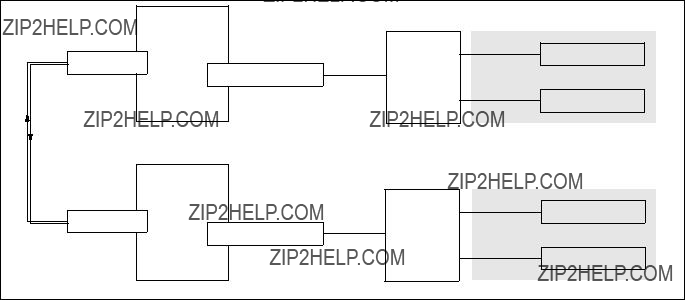
Configuration:
In this scenario, we have the SP Switch of SP21 connected to an GRF 1600. The GRF 1600 has its HIPPI media card???s ports
Figure 71. SP Switch - HIPPI - SP Switch Connection
Table 26 shows the IP addresses used in our configuration.
Table 26. Configuration of SP Switch - HIPPI - SP Switch
To successfully run this configuration, a route to the distant SP Switch network has to be set on every SP Switch Router. On the nodes of SP2 and SP21, respectively, routes to the nodes of the distant SP have to be set.
228 IBM 9077 SP Switch Router: Get Connected to the SP Switch
The media card adapters on the GRF routers should already be up and running (according to Section 3.7,
On the GRF 1600 (HIPPI card is in slot 8, SP Switch card is in slot 3) check for the following:
1. The file /etc/grifconfig.conf has the following entries:
2.The file /etc/grlamap.conf has the following entry (note that ???0x40??? is a hexadecimal value equivalent to 64 decimal):
3. The file /etc/grarp.conf has the following entry
4. The file /etc/grroute.conf has the following line:
192.168.13.0 255.255.255.0 10.50.1.2
This sets the correct route to the other SP Switch network over the HIPPI interface automatically; of course, this route can also be set manually every time the GRF is rebooted.
5.The SP Switch Router Adapter card is connected to the SP Switch and configured. Check with SDRGetObjects switch_responds on the CWS and use Eunfence if needed.
On the GRF 400 (HIPPI card is in slot 0, SP Switch card is in slot 1): 1. The file /etc/grifconfig.conf has the following entries:
2. The file /etc/grlamap.conf has the following entry:
3. The file /etc/grarp.conf has the following entry
4. The file /etc/grroute.conf has the following line:
192.168.14.0 255.255.255.0 10.50.1.1
This sets the correct route to the other SP Switch network over the ATM interface automatically; of course, this route could also be set manually every time the GRF is rebooted.
Multiple RS/6000 SPs and Multiple GRFs 229

5.The SP Switch Router Adapter card is connected to the SP Switch and configured. Check with SDRGetObjects switch_responds on the CWS and use Eunfence if needed.
The following tasks are performed on the respective SP nodes:
1. On the nodes in SP21, the following route needs to be set:
route add
2. On the nodes in SP2, the following route needs to be set:
route add
Hint: You must not use SMIT to set the routes and put them into the ODM. The SP Switch is not working when these routes are set, at boot time. Therefore, they are put onto another, already available network interface, for example the control Ethernet, and this is definitely not what you expect to happen.
Use a separate /etc/rc.routes shell script that is run only after an Estart or an Eunfence was issued, or use some other mechanisms to have this route set only after the css0 interfaces on the SP nodes are up and running.
Setup is done now, and every node in SP2 should now be able to ping every node in SP21 and vice versa.
3. Check for correct routing entries on all nodes in SP21:
4. Check for correct routing entries on all nodes in SP2:
230 IBM 9077 SP Switch Router: Get Connected to the SP Switch

5.Issue some ping commands to check the connection:
On the SP21 nodes, ping the SP Switch interface of nodes in SP2; on nodes in SP2 ping the SP Switch interface of nodes in SP21.
If these ping commands fail, check routing settings again. If everything is as it should be, try to ping the SP Switch Router HIPPI media card or the SP Switch Router Adapter card to find the failing part:
ping 192.168.14.4 (on SP21 processor nodes)
ping 192.168.13.4 (on SP2 processor nodes)
ping 10.50.1.1 and ping 10.50.1.2 (on both the GRF 400 and the GRF 1600)
If any errors occur, check cabling, the configuration of SP Switch Router media cards (see Section 3.7,
Note: Both HIPPI media cards must be online and cabled, or ping will not succeed.
Performance:
To get a rough overview of the data transfer rates that can be achieved in this scenario, the following test was performed:
1.We used ftp to conduct several file transfers of a 300 MB file from the nodes in SP2 to one chosen node in SP21, and at the same time used ftp to conduct several file transfers of a 300 MB file from the nodes in SP21 to a chosen node in SP2. We sent the files to /dev/null on the receiving node to eliminate any hard disk influence.
Multiple RS/6000 SPs and Multiple GRFs 231
We saw up to about 48 MB/s with just one side sending data. With all nodes sending and receiving, we achieved a duplex throughput of about 54 MB/s on the HIPPI port.
232 IBM 9077 SP Switch Router: Get Connected to the SP Switch
Appendix A. Laboratory Hardware and Software Configuration
This appendix contains a detailed description of the hardware and software configuration used to test scenarios described in the second part of this redbook. All hostnames, IP addresses, adapters and other configuration information mentioned there refer to the following section if no other information is given.
A.1 Node and Control Workstation Configuration
This section describes the basic node and CWS configuration used to establish the scenarios.
Table 27 on page 234 and Table 28 on page 235 contain a summary of all nodes in both RS/6000 SPs, their types, hostnames,
Table 27. Configuration of SP 21
234 IBM 9077 SP Switch Router: Get Connected to the SP Switch
Table 28. Configuration of SP 2
A.1.1 Hard Disks
All nodes and CWSs include one or more internal SCSI disks. Some nodes are additionally equipped with SSA disks (Table 29 on page 236). For special tests (Section 5.1.5, ???SP Switch - FDDI Connection in an ADSM Environment??? on page 185) some 9333 Serial Optical Link disks were connected to
selected nodes. Refer to the scenario descriptions in second part of this redbook to see which disks were used.
Table 29. Hard Disk Equipment of SP 21
236 IBM 9077 SP Switch Router: Get Connected to the SP Switch
Table 30. Hard Disk Equipment of SP 2 Part 1 of 2
Table 31. Hard Disk Equipment of SP 2 Part 2 of 2
238 IBM 9077 SP Switch Router: Get Connected to the SP Switch
A.1.2 Software Configuration
Both CWSs and every SP node are installed with AIX 4.3.1, including all fixes available on May 20th, 1998, and PSSP 2.4 PTF Set 1 (See Table 32).
Table 32. Software Levels on CWS and All Nodes Part 1 of 14
Table 33. Software Levels on CWS and All Nodes Part 2 of 14
240 IBM 9077 SP Switch Router: Get Connected to the SP Switch
Table 34. Software Levels on CWS and All Nodes Part 3 of 14
Table 35. Software Levels on CWS and All Nodes Part 4 of 14
242 IBM 9077 SP Switch Router: Get Connected to the SP Switch
Table 36. Software Levels on CWS and All Nodes Part 5 of 14
Table 37. Software Levels on CWS and All Nodes Part 6 of 14
244 IBM 9077 SP Switch Router: Get Connected to the SP Switch
Table 38. Software Levels on CWS and All Nodes Part 7 of 14
Table 39. Software Levels on CWS and All Nodes Part 8 of 14
246 IBM 9077 SP Switch Router: Get Connected to the SP Switch
Table 40. Software Levels on CWS and All Nodes Part 9 of 14
Table 41. Software Levels on CWS and All Nodes Part 10 of14
248 IBM 9077 SP Switch Router: Get Connected to the SP Switch
Table 42. Software Levels on CWS and All Nodes Part 11 of 14
Table 43. Software Levels on CWS and All Nodes Part 12 of 14
250 IBM 9077 SP Switch Router: Get Connected to the SP Switch
Table 44. Software Levels on CWS and All Nodes Part 13 of 14
Table 45. Software Levels on CWS and All Nodes Part 14 of 14
252 IBM 9077 SP Switch Router: Get Connected to the SP Switch
A.1.3 Network Options and Tuning
Table 46 shows the network options on the CWS and all participating SP nodes. Options can be changed with the /etc/no command.
Table 46. Network Options of CWS and All Nodes Part 1 of 3
Table 47. Network Options of CWS and All Nodes Part 2 of 3
254 IBM 9077 SP Switch Router: Get Connected to the SP Switch

Table 48. Network Options of CWS and All Nodes Part 3 of 3
A.2 SP Switch Pool Size Settings
Two important switch parameters were changed from their default values: rpoolsize and spoolsize. To check the current values, enter:
lsattr
and look for rpoolsize and spoolsize. 512 KB per processor is the default size. Both values should be increased if high I/O traffic is expected on the SP Switch. To increase both values to 5 MB (as applied in all of our scenarios), enter:
/usr/lib/methods/chgcss
For the changes to take effect, the SP nodes must be rebooted.

A.3
A
Table 49. Network Options of
256 IBM 9077 SP Switch Router: Get Connected to the SP Switch
Table 50. Network Options of

Table 51. Network Options of
A.4 SP IP Switch Router Configuration
A GRF 400 and/or a GRF 1600 SP Switch Router were used for all the tests. Ascend Embedded/OS 1.4.6.4 was installed.
Both Switch Routers contain at least one SP Switch Router Adapter card. Depending on the scenario, several SP Switch Router media cards were installed, including Ethernet, FDDI, ATM
258 IBM 9077 SP Switch Router: Get Connected to the SP Switch
The applied IP addresses vary with the scenario and are specified in the corresponding chapter. For specific SP Switch Router sample configuration files, refer to Appendix B, ???GRF Configuration Files??? on page 261.
260 IBM 9077 SP Switch Router: Get Connected to the SP Switch

Appendix B. GRF Configuration Files
This appendix contains relevant SP Switch Router configuration files.
Some of them are here just for information, some of them were worked out manually during setup of hardware or software and some of them were created using
Also, make use of the man utility that is running on the SP Switch Router. Although there are no entries for basic operating system commands, the GRF specific commands, which can be recognized by their gr- prefix, do.
B.1 /root/.profile
The following is a modified /root/.profile for the root user. We liked to have a system prompt that shows the hostname and path. We also preferred emacs command line settings over the vi settings.
We further commented out the call to the command line interface (CLI), because most of the time when you log onto the GRF, you will be working with a shell anyway. CLI can be started with the command ncli.
Because the file /root/.profile is not located in the /etc directory, it must be saved with the grsite command to be there after system reboot. If you want the modified file to survive even software updates, use grsite
#
#NOTE: This file is considered part of the Ascend GRF software,
#and may be overwritten by future releases of Ascend GRF
#software. IF YOU EDIT THIS FILE DIRECTLY, YOUR CHANGES
#MAY BE LOST WHEN YOU UPGRADE SOFTWARE.
#
#To allow local customization of the root login, this
#script will look for the file .profile.local and source
#it in if it exists. This should allow you to set
#environment variables or execute initialization commands
#in that file.
#
#If you find that you cannot adequately customize your
#root account???s login process through .profile.local, and
#must customize it by editing this file directly, then of
#course, do what you need to make things work.
#
#If you find that you must edit this .profile script directly,
#please inform the High Performance Networking Division of
#Ascend Communications (through normal support channels) of
#the change you needed to make to this .profile script, so
#that we may consider enhancing it in future software
#releases to support your needs.
#
#
# GRF systems require /usr/nbin in the path.
#
PATH=/sbin:/usr/sbin:/bin:/usr/bin:/usr/local/bin:/usr/contrib/bin:/usr/nbin export PATH
echo ???erase ^H, kill ^U, intr ^C status ^T??? stty crt erase kill - intr status
umask 022
HOME=/root export HOME
BLOCKSIZE=1k export BLOCKSIZE
#
#Enable
FCEDIT=vi
#We prefer VISUAL=emacs /*UU*/
VISUAL=emacs export FCEDIT export VISUAL
#gimme a meaningful prompt /*UU*/ export PS1
#take care, the following is a command substitution,
#so this ??? is a backtick. (that ??? is a aingle quote) host=???hostname
export host PS1="$host:\$PWD "
#
#Look for a local .profile.local file, owned by root,
#and source it in if such a thing exists.
#
#NOTE: Do NOT put an "exit" statement in the .profile.local file.
#Because we source it in, an "exit" statement in
#.profile.local will cause the login shell to terminate.
#
#... and if you use this .profile.local, dont forget to
#grsite
LOCAL=./.profile.local if [
if [ X???find ${LOCAL}
OWNER=???ls
echo "???${LOCAL}??? owned by ???${OWNER}???, not ???root???; skipping sourc
ing it." >&2 else
. ${LOCAL}
fi
fi
unset LOCAL
#
# Check to see if this is an interactive session.
262 IBM 9077 SP Switch Router: Get Connected to the SP Switch
#
if [
#
# Ask for a terminal type; the default is the canonical "vt100".
#
if [ X${TERM} = X ] then
TERM=vt100
fi
eval ???tset
#
#It???s interactive, so exec the new CLI shell for the GRF.
#from here on commented out the next 15 lines as 99.99999% of work
#is from the shell prompt, and if you exit from CLI, .profile is not
#obeyed, sigh.
#you have to call ncli, to get the super> prompt.
#to see the information that pops up, if you start sh within super>,
#cat /etc/motd, or run sh within super> /*UU*/
#NCLI=/usr/nbin/ncli
#if [
#then
#${NCLI}
#STATUS=$?
#if [ ${STATUS}
#exit 0
#fi
#echo "???${NCLI}??? exited status ${STATUS}; continuing with ???${SHELL}???."
#elif [
#then
#echo "Warning: ???${NCLI}??? is not executable; using ???${SHELL}???.
"
# else
# echo "Warning: ???${NCLI}??? is not found; using ???${SHELL}???."
#fi
#end of commenting out the call to CLI. /*UU*/ fi
B.2 /etc/Release
This file???s only content is the actual version of the operating system the GRF is running. If in doubt, look here and also have a look at Appendix B.15, ???/etc/motd??? on page 287.
A_1_4_6_ibm,default
GRF Configuration Files 263

B.3 /etc/bridged.conf
This file holds the configuration data for transparent bridging. It is created using the utility bredit.
#
#NetStar $Id$
#Configuration file for Bridge Daemon (bridged).
#Note: bridged will not start if it finds an error while
#trying to parse this file. Use the
#command line with bridged to find proximity of the offending
#line.
#
#
#bridge_group bg0 {
#
#The main reason we need to configure this stuff is to
#specify which ports are part of a bridge group.
#
#Declare all the ports in this group on a single
#line if you don???t need to set anything special
#for the port. This is the normal case.
#
#multiple lines are ok.
#eg. port gf070;
#port gf041 gf072;
#port gf080;
#
#port gf000 gf001 gf002 gf003;
#
#If you need to set specific values for a port in this
#bridge group, then use the structure below..
#
# port gf040 {
#
#
#priority : port priority allows the network manager to
#influence the choice of port when a bridge has
#two ports connected in a loop.
#
#priority 5;
#valid states are : blocking, listening, learning and
#forwarding. the default start state is blocking.
#state blocking;
#
#root_path_cost : This is the cost to be added to the root
#path cost field in a configuration message received
#on this port in order to determine the cost of the
#path to the root through this port. This value is
#individually settable on each port.
#
#Setting this value to be large on a particular port
#makes the LAN reached through that port more likely
264 IBM 9077 SP Switch Router: Get Connected to the SP Switch
#to be a lead or at least low in the spanning tree.
#The closer a LAN is to being a leaf in the tree, the
#less through traffic it will be asked to carry. A
#LAN would be a candidate for having a large path
#cost if it has a lower bandwidth ot if someone wants
#to minimize unnecessary traffic on it. A better
#description is possibly link cost or port cost.
#
#root_path_cost 5;
#Forward packets with the following destination addresses
#through this port.
#
# forward 00:a0:24:2a:50:e6 00:a0:24:2a:50:e7;
#
#};
#port gf041 {
#state blocking;
#root_path_cost 6;
#priority 5;
#};
#
#Configuration and tuning parameters that
#govern how a bridge group functions.
#
#priority: This is used to create the bridge ID for
#this bridge. this along with the MAC address of one
#of the ports in the group is used to set the bridge ID.
#This value allows the network manager to influence the
#choice of root bridge and the designated bridge. It is
#appended as the most significant portion of a bridge ID.
#A lower numerical value for bridge priority makes the
#bridge more likely to become the root.
#
#priority 128;
#hello_time: Interval between the transmission of configuration
#BPDUs by a bridge that is attempting to become the root
#bridge or is root bridge.
#It is the timer that elapses
#between generation of configuration messages by a bridge
#that assumes itself to be the root.
#Shortening this time will make the protocol more
#robust, in case the probability of loss of configuration
#messages is high. Lengthening the timer lowers the overhead
#of the alogorithm (because the interval between transmission
#of configuration messages will be larger).
#
#The recommended time is 2 sec.
#hello_time 2 seconds;
#
#forward_delay: The time value advertised by this
#bridge for deciding the time delay that a port must
#spend in the listening and learning states.
#
#This parameter temporarily prevents a bridge from starting
#to forward data packets to and from a link until news of
#a topology change has spread to all parts of a bridged
#network. This shousl give all links that need to be turned
#off in the new topology time to do so before new links are
GRF Configuration Files 265
#turned on.
#Setting the forward delay too small would result in temporary
#loops as the spannign tree algorithm converges. Setting this
#value too large results in longer partitions after the
#spanning tree reconfigures.
#
# The recommended value is 15 sec.
#forward_delay 15 seconds;
#
#maximum_age: This is the time value advertised by this bridge for
#deciding whether to discard spanning tree frames based on
#message age.
#
#If the selected max_age value is too small, then occasionally,
#the spanning tree will reconfigure unnecessarily, possibly
#causing temporary loss of connectivity in the network. If the
#selected value is too large, the network will take longer then
#necessary to adjust to a new spanning tree after a topological
#event such as restarting or crashing of a bridge or link.
#
#The recommended value is 20 sec.
#maximum_age 20 seconds;
#
#route_maximum_age: This parameter determines how often routes
#will be aged out of the learnt route table.
#
#Default : 300 seconds
#route_maximum_age 300 seconds;
#And last, hardwiring the forwarding table with
#specific MAC addresses to discard.
#
#Sink packets with the following destination
#addresses.
#
#discard 00:40:0b:0c:95:60 00:40:0b:0c:95:6a;
#Disable Spanning Tree for the group
#
#spanning_tree disabled
#} ;
#
#To create a bridge group with no ports in it, use the
#following NULL declaration:
#
#bridge_group bg0 {
# For FDDI Backbone test Chap.5.1.4.2 bridge_group bg0 {
port gf000 gf001 gf002 gf003;
};
266 IBM 9077 SP Switch Router: Get Connected to the SP Switch

#For ATM - ATM two ports Test Chap.7.1.2 bridge_group bg1 {
port ga010 ga0180;
#spanning_tree disabled;
};
B.4 /etc/fstab
This file holds the filesystem mount information. This file was changed when adding a PCMCIA hard disk in Section 3.3.2, ???Installing the PCMCIA Spinning Disk??? on page 76.
#
#Filesystem mount table information. See the fstab(5) man page
#and the /etc/fstab.sample file for more information and examples.
#Each line is of the form:
#Note that multiple flags (when used) are specified as a
#comma separated list without spaces.
#
# Blank lines and lines beginning with ???#??? are comments.
#
#Example line to mount a remote file system in such a way that it
#will try to mount for a long time and is interuptable:
B.5 /etc/grarp.conf
This file holds ARP information for distant interfaces that do not support inverse ARP.
#NetStar $Id: grarp.conf,v 1.2.22.1 1997/05/09 17:35:00 jim Exp $
#Template grarp.conf file.
#
#This file contains any hardwired
#mappings you may want for GigaRouter interfaces. It is especially
#important for HIPPI, whose ARP tables are manually configured.
#For HIPPI, this file replaces the "gria" command.
GRF Configuration Files 267

#following formats:
#
#Ethernet or FDDI: xx:xx:xx:xx:xx:xx
#
#HIPPI:
#
#This is the HIPPI Interface from Chap.7.3
#This is on grf16, 10.50.1.2 and 0x03666fc0 is grf4
B.6 /etc/gratm.conf
In this file, the parameters for ATM
#
#NetStar $Id$
#gratm.conf - GigaRouter ATM Configuration File
#
#This file is used to configure GigaRouter ATM interfaces.
#Statements in this file are used to configure ATM PVC???s,
#signalling protocols, arp services, and traffic shapes.
#gratm(8) uses this file as input when it is run by grinchd(8)
#whenever an ATM media card boots to configure the card.
#
#
#gratm.conf is divided into five sections:
#The Service section is where ATM ARP services are defined (entries
#defined in this section are referenced from the Interface section
#of this file to define which ARP service an interface should use).
#The Traffic Shaping section is where traffic shapes are defined (entries
#defined in this section are referenced from the Interface and PVC
#sections of this file to define which traffic shapes interfaces
#and PVC???s should use).
#
#The Signalling section is where the signalling protocol to be used
#by a physical interface to establish Switched Virtual Circuits
#is specified.
#
#The Interfaces section is where
#such as ARP services and Traffic shapes are bound to specific
#logical interfaces.
#
268 IBM 9077 SP Switch Router: Get Connected to the SP Switch
#The PVC section is where Permanent Virtual Circuits are defined,
#using traffic shapes defined in the Traffic Shaping section,
#along with other parameters specific to PVC configuration.
#
#Notes on the format of this file:
#Comments follow the Bourne Shell style (all characters following a #
#on a line are ignored).
#
#Statements in this file are separated by newlines. A statement may
#span multiple lines by ending each incomplete line of the statement
#with a ???\??? character. Example:
#
# Traffic_Shape name=high_speed peak=15000 # this is a statement
#
# Service name=bc0 type=bcast addr=198.174.11.1 \ # this is also a statement
#addr=198.176.11.1
#
#before they are used, ie., the definition of a traffic shape must
#precede its use in an Interface or PVC specification, and the
#definition of a Service must precede the use of the name of that
#service in defining any Interfaces.
#
#
#ARP Service info
#Lines beginning with the keyword "Service" define virtual "services" which
#may or may not be present on an ATM network attached to a GigaRouter.
#
# Each Service entry the ATM configuration file has the following format:
#The "name" field is a unique name to identify this ATM service
#The "type" field specifies the type of ATM service being configured.
#and how the address argument(s) which follow are interpreted.
#Service name=arp0 type=arp addr=47000580ffe1000000f21513eb0020481513eb00
GRF Configuration Files 269
#Service name=bc0 type=bcast addr=198.174.20.1 addr=198.174.22.1 \
#addr=198.174.21.1
#
#Traffic shaping parameters
#Lines beginning with the keyword "Traffic_Shape" define
#traffic shapes which may be used to configure the performance
#characteristics of ATM Virtual Circuits.
#The Traffic_Shape???s defined here are to be referenced by name when
#to assign traffic shapes to PVC???s or Interfaces later in this
#configuration file. (See Examples in the PVC or Interface section
#of this file for examples on how to reference traffic shapes defined here.)
#Each Traffic_Shape entry the ATM configuration file has the following format:
#Traffic_Shape name=value peak=bps [sustain=bps burst=cells] [qos=high|low]
#
#The "name" field is a unique name to identify this ATM service, so we
#can refer to the collection of peak, [sustain, burst], [qos] parameters
#as a group when configuring PVC???s or Interfaces later in this file.
#
#The ???peak???, ???sustain???, and ???burst??? fields specify, respectively,
#the peak cell rate, the sustained cell rate, and the burst rate.
#The values for ???peak??? and ???sustain??? are in kilobits per second (maximum
#of 155000), and the value for ???burst??? is in cells (maximum of 2048).
#
#The ???qos??? (Quality of Service) field specifies which rate queues
#to use. A value of ???high??? corresponds to high priority service
#which uses the
#to low priority service which uses the
#
#The peak rate is the only parameter which is mandatory. If ommitted,
#the sustain and burst rates are set to match the peak rate. If qos
#is not specified, it defaults to "high".
#
#Traffic_Shape name=high_speed_high_quality \
#peak=155000 sustain=155000 burst=2048 qos=high
#Traffic_Shape name=medium_speed_low_quality \
#peak=75000 qos=low
#Traffic_Shape name=low_speed_high_quality \
# peak=15000 qos=high
#
#Signalling parameters
#Lines beginning with the keyword "Signalling" define
#the signalling protocol which will be used on a physical
#ATM interface to establish Switched Virtual Circuits for
#any logical interfaces on the named physical interface.
#Physical interfaces on GigaRouter ATM cards are identified by
#the slot number of the interface card in the GigaRouter chassis
#in hex notation
#on the card (either the top connector, or the bottom connector on the card).
#Each Signalling entry the ATM configuration file has the following format:
#Signalling card=hex connector=top|bottom [protocol=UNI3.0|UNI3.1|NONE] \
270 IBM 9077 SP Switch Router: Get Connected to the SP Switch
#[mode=SDH|SONET] [clock=Ext|Int]
#The ???card??? and ???connector??? specification are mandatory.
#The card should be identified by a hexidecimal digit representing
#the slot number of the card in the GigaRouter chassis.
#
#The connector should be either ???top??? or ???bottom???.
#The ???protocol??? parameter defines the signalling protocol to be used
#in the setup of Switched Virtual Circuits (SVC???s) on this physical
#interface. This parameter is optional. If left unspecified, the
#ATM card uses UNI3.0 signalling by default.
#
# Valid values for the signalling parameter include:
#The ???mode??? specification is optional. It can be either SDH or SONET.
#By default, it uses SONET.
#
#The ???clock??? specification is also optional. It can be either Ext(ernal)
#or Int(ernal). The default setting is Internal clocking.
#
#Signalling card=9 connector=top protocol=UNI3.1 #Signalling card=9 connector=bottom protocol=NONE
#Signalling card=a connector=top protocol=UNI3.1 #Signalling card=a connector=bottom protocol=NONE
#
#Interfaces
#Lines beginning with the keyword "Interface" define
#GigaRouter logical ATM interfaces.
#The format of a logical interface definition is:
#Interface ifname [service=service_name] [traffic_shape=shape_name] \
#[bridge_method=method[,restriction]]
#
#The optional ???service??? parameter allows an ATM service to be
#be defined for this logical interface (the ???service_name??? must be
#a name defined in the Services section above).
#
#The optional ???traffic_shape??? parameter allows a traffic shape
#to be defined for this logical interface (the ???shape_name??? must be
#a named defined as a Traffic_Shape above).
#
#If no traffic shape is specified, a default shape of 155Kbps, high
#quality of service is used.
#
#The optional ???bridge_method??? parameter allows an interface to be used
#for RFC 1483 bridging. The valid values for the bridge_method parameter
#are:
GRF Configuration Files 271
#LLC encapsulated bridging allows any LAN frame type to be transmitted, and
#also allows IP datagrams to be sent directly on the VC. The optional
#???restriction??? parameter can limit how IP datagrams are routed to the
#interface, and on what kind of LAN frames are transmitted on it.
#The valid values for the restrction parameter are:
#Note that unless a restriction or an ARP service is specified, an
#
#the other end of the ATM PVC.
#Interface ga090 service=arp0 traffic_shape=high_speed_high_quality #Interface ga0980 service=net20 traffic_shape=low_speed_high_quality
#Interface ga0a0 service=arp0 traffic_shape=high_speed_high_quality #Interface ga0a80 service=net20 traffic_shape=low_speed_high_quality
#Interface ga091 traffic_shape=high_speed_high_quality \
#bridge_method=llc_encapsulated,broute_to_ether
#
#PVC???s
#Lines beginning with the keyword "PVC" define
#Permanent virtual circuits.
#The format of a PVC definition is:
#PVC ifname VPI/VCI \
#proto=ip|raw|vc|ipnllc|isis|llc[,bridging]|vcmux_bridge,bpro|vc_atmp \
#[input_aal=3|5|NONE] [traffic_shape=shape] \
#[dest_if=logical_if [dest_vc=VPI/VCI]]
#
#The first three parameters (ifname, VPI/VCI, and proto) are mandatory.
#???ifname??? specifies the GigaRouter ATM logical interface in the usual
#format (e.g., ga030, ga0e80).
#
#???VPI/VCI??? specifies the (decimal) Virtual Path Identifier and
#Virtual Circuit Identifier of the PVC, separated by a slash (/).
#???proto??? specifies the protocol to be supported on this PVC. Legal
#values are:
272 IBM 9077 SP Switch Router: Get Connected to the SP Switch
#If the ???proto??? specified is ???raw???, the ???dest_if??? parameter specifies the
#GigaRouter interface of the destination for this raw adaptation layer
#connection (specified in the same GigaRouter interface format
#described above), and (optionally) the dest_vc parameter specifies
#the destination VPI/VCI.
#
# the ???input_aal??? parameter may be used to specify the adaptation layer,
#The optional ???traffic_shape??? parameter allows a traffic shape
#to be defined for this logical interface (the ???shape_name??? must be
#a named defined as a Traffic_Shape above).
#
#If no traffic shape is specified, a default shape of 155Kbps, high
#quality of service is used.
#
#PVC ga090 0/32 proto=ip traffic_shape=high_speed_high_quality #PVC ga0980 0/32 proto=ip traffic_shape=high_speed_high_quality
#PVC ga0a0 1/33 proto=raw traffic_shape=high_speed_high_quality \
#dest_if=ga090 dest_vc=5/50 input_aal=5
#PVC ga0a80 1/33 proto=ip traffic_shape=high_speed_high_quality
#PVC ga0b0 0/40 proto=isis traffic_shape=high_speed_high_quality #PVC ga0c0 0/41 proto=isis_ip traffic_shape=high_speed_high_quality
#PVC ga030 0/32 proto=llc,bridging
#PVC ga031 0/32 proto=vcmux_bridge,ether_nofcs #PVC ga031 0/33 proto=vcmux_bridge,fddi_nofcs #PVC ga031 0/34 proto=vcmux_bridge,bpdu
#Here come the different settings we used during
#the residency.
Traffic_Shape name=high_speed_high_quality \ peak=155000 sustain=155000 burst=2048 qos=high
Traffic_Shape name=low_speed_high_quality \ peak=15500 qos=high
# ATM
Traffic_Shape name=bigg_speed_high_quality \
GRF Configuration Files 273

peak=622000 sustain=622000 burst=2048 qos=high
Signalling card=1 connector=top protocol=NONE
Signalling card=1 connector=bottom protocol=NONE
#Interface ga010 traffic_shape=high_speed_high_quality
#PVC ga010 0/132 proto=ip traffic_shape=high_speed_high_quality
Interface ga010 traffic_shape=high_speed_high_quality \ bridge_method=vc_multiplexed
PVC ga010 0/132 proto=vcmux_bridge,bpdu
PVC ga010 0/133 proto=vcmux_bridge,ether_nofcs PVC ga010 0/134 proto=vcmux_bridge,fddi_nofcs PVC ga010 0/135 proto=llc
#PVC ga010 0/136 proto=ip
#Interface ga0180 traffic_shape=high_speed_high_quality
#PVC ga0180 0/134 proto=ip traffic_shape=high_speed_high_quality
Interface ga0180 traffic_shape=high_speed_high_quality \ bridge_method=vc_multiplexed
PVC ga0180 0/144 proto=vcmux_bridge,bpdu
PVC ga0180 0/145 proto=vcmux_bridge,ether_nofcs PVC ga0180 0/146 proto=vcmux_bridge,fddi_nofcs PVC ga0180 0/147 proto=llc
#PVC ga0180 0/148 proto=ip
#
Interface ga020 traffic_shape=bigg_speed_high_quality
PVC ga020 0/132 proto=ip traffic_shape=bigg_speed_high_quality
B.7 /etc/grclean.conf
This file contains the specifications on how to handle log file management on the GRF. It includes the file /etc/grclean.logs.conf, where the location of the log files in the filesystem is handled. See Appendix B.8, ???/etc/grclean.logs.conf??? on page 275 for further reference.
################################################################################
#NetStar $Id: grclean.conf,v 1.10.4.1 1997/08/27 19:58:30 jeanne Exp $
################################################################################
#grclean configuration file
274 IBM 9077 SP Switch Router: Get Connected to the SP Switch

# DEFAULTS sets all of the above keywords to the above defaults.
################################################################################
################################################################################
# log files.
################################################################################
include=/etc/grclean.logs.conf
################################################################################
################################################################################
################################################################################
# port card dump files.
################################################################################
hold=4
size=1
remove=y
local=y logfile=/var/portcards/grdump.*
################################################################################
B.8 /etc/grclean.logs.conf
This file is included from /etc/grclean.conf. Take special care of the location of the log files once a PCMCIA hard disk is installed. Refer to Section 3.3.2, ???Installing the PCMCIA Spinning Disk??? on page 76.
#NetStar $Id: grclean.logs.conf,v 1.9.2.3 1997/08/27 19:58:31 jeanne Exp
$
################################################################################
#grclean configuration file
################################################################################
################################################################################
#of some interest.
#console log file.
#boot log file.
################################################################################
ash=kill
local=y
################################################################################
GRF Configuration Files 275
#Log files that used to be archived by the /etc/{daily|weekly|monthly}
#scripts.
################################################################################
size=10000
logfile=/var/account/acct
size=10000
logfile=/var/log/maillog
size=150000
logfile=/var/log/messages
size=10000
logfile=/var/log/daemon.log
size=10000
logfile=/var/log/cron
size=10000
logfile=/var/log/xferlog
size=10000 logfile=/var/log/httpd/access_log size=10000 logfile=/var/log/httpd/error_log size=10000 logfile=/var/log/ftp.log size=10000 logfile=/var/log/kerberos.log size=10000
size=10000
logfile=/var/log/gritd.packets
size=150000
logfile=/var/log/gr.console
size=11000
logfile=/var/log/gr.boot
size=150000
logfile=/var/log/grinchd.log
size=10000
logfile=/var/log/gr.conferrs
size=25000
logfile=/var/log/mib2d.log
size=25000
logfile=/var/tmp/gated.rip
size=25000
logfile=/var/log/mibmgrd.log
size=25000
logfile=/var/log/cli.log
size=75000
logfile=/var/log/fred.log
################################################################################
# Process site specific clean conf, if any.
################################################################################
include=/etc/grclean.site.conf
################################################################################
# /var/tmp/core.* file cleanup.
################################################################################
hold=1
remove=y
size=1024 logfile=/var/tmp/core.*
################################################################################
# cleanup our own log file, if necessary.
################################################################################
276 IBM 9077 SP Switch Router: Get Connected to the SP Switch

DEFAULTS hold=2 local=y size=10000
logfile=/var/log/grclean.log
B.9 /etc/grdev1.conf
This file normally gets updated automatically by the SNMP daemon running on the CWS.
############################################################################
#DEV1 Configuration
###########################################################################
#There are several variables that an SP Adapter card needs at start up.
#These are handled by a set of GRINCHES whose descriptors are indexed
#by card number and interface number as follows:
#
#2.21.{CARD+1}.1.{INTERFACE+1}
#This template specifies the
#in a
#that the card needs to be configured.
#
#The descriptors are grouped by card and interface so that a particular
#interface can be easily configured.
#
############################################################################
#
2.21.1.1.1.3"00:00:00:00:00:00:00:00:00:00" # Switch Token
2.21.2.1.1.3"00:00:00:00:00:00:00:00:00:00" # Switch Token
GRF Configuration Files 277
2.21.3.1.1.3"00:00:00:00:00:00:00:00:00:00" # Switch Token
2.21.4.1.1.3"00:00:00:01:00:00:00:06:00:01" # Switch Token
2.21.5.1.1.3"00:00:00:00:00:00:00:00:00:00" # Switch Token
278 IBM 9077 SP Switch Router: Get Connected to the SP Switch
2.21.6.1.1.3"00:00:00:01:00:00:00:07:00:03" # Switch Token
2.21.7.1.1.3"00:00:00:00:00:00:00:00:00:00" # Switch Token
2.21.8.1.1.3"00:00:00:00:00:00:00:00:00:00" # Switch Token
2.21.9.1.1.3"00:00:00:00:00:00:00:00:00:00" # Switch Token
GRF Configuration Files 279
2.21.10.1.1.3"00:00:00:00:00:00:00:00:00:00" # Switch Token
2.21.11.1.1.3"00:00:00:00:00:00:00:00:00:00" # Switch Token
2.21.12.1.1.3"00:00:00:00:00:00:00:00:00:00" # Switch Token
280 IBM 9077 SP Switch Router: Get Connected to the SP Switch
2.21.13.1.1.3"00:00:00:00:00:00:00:00:00:00" # Switch Token
2.21.14.1.1.3"00:00:00:00:00:00:00:00:00:00" # Switch Token
2.21.15.1.1.3"00:00:00:00:00:00:00:00:00:00" # Switch Token
2.21.16.1.1.3"00:00:00:00:00:00:00:00:00:00" # Switch Token
GRF Configuration Files 281

B.10 /etc/grifconfig.conf
This file documents the correlation of the logical interfaces on the media cards in the GRF to IP addresses, together with some other information, like MTU.
#NetStar $Id: grifconfig.conf,v 1.10.2.3 1997/08/01 17:24:04 pargal Exp $
#Configuration file for GigaRouter/GRF interfaces.
#
#The contents of this file specify the IP addressing information for
#the networks attached to the system???s interfaces. This includes
#interfaces on media cards as well as directly attached interfaces
#such as de0 or ef0 (maintenance Ethernet) or lo0 (software loopback).
#The addresses of directly attached interfaces are configured
#directly from this file by the /etc/netstart calling the grifconfig(8)
#script.
#
#The addresses of the interface(s) on a given media card are
#configured into the BSD/OS kernel when the media card boots and
#comes on line.
#The name of a GigaRouter interface encodes the hardware type,
#GigaRouter cage number, slot number, and interface number.
#
#
#interface).
#
#interface: ???a??? for ATM, ???e??? for ETHERNET,
#???f??? for FDDI, ???h??? for HIPPI, ???p??? for PPP, ???s??? for HSSI.
#(???l??? is also used, for GigaRouter software loopback.)
#
#(Currently this must be ???0???, as multiple GigaRouter cages
#are not yet supported.)
#
#the slot number within the GigaRouter cage.
#
#LOGICAL interface on the card:
#
#For ATM cards, the fifth and sixth characters are
#the hex digits of the logical interface. Logical
#interfaces numbered from 0 to 7f are on the top
#physical connector on the ATM card, and logical
#interfaces numbered 80 to ff are on the bottom
#physical connector. NOTE: These logical interface
#numbers are NOT the same as the VPI/VCI numbers
#of a PVC (see /etc/grpvc.conf for that).
#
#For FDDI cards, the fifth character will be 0, 1,
#2, or 3 to specify the logical interface on the
282 IBM 9077 SP Switch Router: Get Connected to the SP Switch
#FDDI card. NOTE: The logical interface number
#may be different from the physical interface on
#the card, depending on the single- or dual-
#attachedness of the various interfaces. Examples:
#"gf073" specifies the
#on the FDDI card in slot 7; "gf020" specifies
#
#or the top TWO connectors on that card if they???re
#configured
#For ETHERNET cards, the fifth character will be 0, 1,
#2, 3, 4, 5, 6 or 7 to specify the physical interface
#on the ETHERNET card.
#Examples:
#"ge067" specifies the 8th physical connector
#"ge000" specifies the first (top) connector on the
#"ge0f7" specifies the last (bottom) connector on the
#For HIPPI cards, which only have one interface,
#the fifth character is always 0. Example:
#"gh0f0" specifies the interface for a HIPPI card
#in slot 15.
#The IP "address", "netmask" (optional), and "broad_dest" (optional)
#address fields must be specified in canonical IP
#An entry of
#fields as a
#is desired but a broadcast or destination address must be specified
#in the next field.
#
#
#For this release, the "broad_dest" field specifies the broadcast
#IP address for Ethernet & FDDI interfaces, and the destination of
#a
#
#The "arguments" field is for any additional arguments to be supplied
#to the underlying ifconfig(8) command that will be executed by
#grifconfig(8). The most useful purpose would be to specify an
#MTU value for the interface using the "mtu" keyword of ifconfig(8).
#The keyword "iso" can also be specified here which designates the current
#line as an iso address entry.
#See the example entry below, and the man page for ifconfig(8).
#
#
#NOTE: All interface names are case sensitive ! Always use lower case letters
#when defining interface names.
GRF Configuration Files 283

B.11 /etc/grlamap.conf
This file contains the mapping of logical addresses to destination portcards for HIPPI interfaces. We used this file in Section 7.3, ???HIPPI Backbone Connection??? on page 227.
#NetStar $Id: grlamap.conf,v 1.1 1995/02/09 20:29:27 scotth Exp $
################################################################################
#There are 3 fields to determine how logical addresses get
#mapped to destination portcards for each hippi portcard.
#
#The first field is a comma separated list which determines the
#portcard on which the other 2 fields will apply.
#Ranges are allowed. i.e.,
#???*??? signifies that all portcards get this mapping.
#The second field is a comma separated list of logical addresses being mapped.
#Ranges are allowed.
#values: 0 - 4095 inclusive, ???*??? signifies the default (i.e., all LAs).
#
#The third field is a comma separated list of destination port cards.
#Only the first 4 values will be taken as valid, any extra values will
#be flagged invalid, a message will be printed to gr.console & grlamap will
284 IBM 9077 SP Switch Router: Get Connected to the SP Switch

#exit.
#If only 3 values are designated, the first value will be repeated as the
#fourth value.
#
#No whitespace is allowed in any field.
#ie.
#When port cards 5 & 6 receive an IP packet with a logical address of 997 or
#998, it will then attempt to randomly forward the packet to one of the
#mapped ports 1, 4, 8 or 15.
#
################################################################################
################################################################################
# IP mapping.
################################################################################
################################################################################
B.12 /etc/grroute.conf
Contains the default route one is supposed to provide during first installation. Routes to selected networks may also be entered here and will be brought up automatically during start up procedures of the SP Switch Router.
#NetStar $Id: grroute.conf,v 1.3 1995/03/15 22:09:07 knight Exp $
#grroute.conf
#This file should only contain routes to remote networks and
#
#GigaRouter interface. Routes for networks directly attached
#to the GigaRouter are created as part of configuring the
#GigaRouter interfaces; see /etc/grifconfig.conf.
#
#NOTE: THIS FILE SHOULD NOT BE USED ON SYSTEMS WITH DYNAMIC
#ROUTING (gated). If you are running gated, then you should specify
#static routes using the "static" statement in /etc/gated.conf.
#
#Whenever a port card boots, comes on line and has its interface(s)
#configured, the routes specified in this file that are for gateways
#on the network(s) directly attached to those interface(s) are
#configured into the BSD/386 kernel.
#The destination is the IP address of the remote host or network.
#For the default route, specify a destination of "0.0.0.0" or the
#word "default".
#
GRF Configuration Files 285

#A netmask is required for all entries in this configuration file.
#The netmask is normally the mask of the remote network:
#For remote host routes, specify a netmask of 255.255.255.255:
#192.0.2.1 255.255.255.255 123.45.67.89
#
#In the case of the default route (0.0.0.0), the netmask is ignored,
#but some value must be present for the file to parse correctly.
#preferred routes during the residency
#192.168.13.0 255.255.255.0 10.1.1.2 192.168.13.0255.255.255.0 10.20.30.2
B.13 /etc/hosts
The file /etc/hosts contains the correlation between IP addresses and hostnames.
#
#Host Database
#This file should contain the addresses and aliases
#for local hosts that share this file.
#It is used only for "ifconfig" and other operations
#before the nameserver is started.
B.14 /etc/inetd.conf
This file is included here just for curiosity in case you are interested in why ftp to the GRF is not possible.
286 IBM 9077 SP Switch Router: Get Connected to the SP Switch

B.15 /etc/motd
This file contains the greeting message of the system and within this information about the running version and release of the operating system.
Complement this information with the content of Appendix B.2, ???/etc/Release??? on page 263.
Ascend Embedded/OS GR TA1.4.6.4 Kernel #0 (nit): Wed Mar 4 10:10:10 CST 1998
Ascend Embedded/OS 1.4.6
Copyright 1992,1993,1994,1995,1996,1997,1998 Ascend Communications, Inc.
IMPORTANT: By use of this software you become subject to the terms and conditions of the license agreement on file /etc/license and any other license agreements previously provided to you by Ascend Communications.
B.16 /etc/rc.local
Use this file for local modifications that are to be carried out during boot.
GRF Configuration Files 287

#NetStar $Id: rc.local,v 1.1 1997/01/15 07:45:03 stuarts Exp $
#
#By default on a GRF, there, there are no local daemons, so
#just comment out the
#Uncomment this line (and the trailing "echo ???.???" line below)
#if you really do have local daemons and want this sort of
#
#echo
#An example of starting a local daemon.
#Uncomment, replicate, and modify as needed for your local daemons.
#echo
#Terminate the
#Put other local customizations here...
#Have to put this in here on demand. See README for 1.4.6.4 sysctl
#Exit with a successful return status.
exit 0
B.17 /etc/snmpd.conf
This file is used to specify access and control permissions to the snmp demon. During first installation, the CWS has to be added to this file; see Section 3.8, ???Step 1. Check SNMP in the SP Switch Router System??? on page 88 and Section 3.9, ???Put SNMP Changes into Effect??? on page 89.
#
#Default Agent Configuration File
#This file allows MANAGERS to be specified. This is used to
#specify which managers will be receiving which traps.
#
#Also, COMMUNITYs can be specified. This allows that agent to
#be configured such that it will only except requests from
#certain managers and with certain community strings.
288 IBM 9077 SP Switch Router: Get Connected to the SP Switch
#
#
#ALLOW <subagentId> [ON <hostSpec>]
#WITH <passwordSpec> [<entitySpec>] [<timeout>]
#DENY <subagentId> ON <hostSpec> WITH <passwordSpec>
#ENTITY <EntityName> DESCRIPTION <String>
#
#LOCAL CONTEXT <contextName> [USES] VIEW <viewName>
#REFERS TO ENTITY <entityName> AS <oid>
#
#PROXY CONTEXT <oid> [USES] SOURCE PARTY <oid>
#VIEW <viewName> [[INCLUDE | EXCLUDE] SUBTREE <oid> [MASK <bitmask>]]+
#ALLOW op [,op]* [OPERATIONS] <sugar> SOURCE PARTY <partyName>
#<partyDefinition> ::= [LOCAL] PARTY <name> ON TRANSPORT <transport>
#<transport> ::= [ snmpUDPDomain | snmpCLNSDomain | snmpCONSDomain |
#<transport> ::=
#<AuthPriv> ::= <noAuth> <noPriv> |
#<noAuth> ::= <sugar> NO AUTHENTICATION
#<sugar> ::= [AND] [[WITH | USING]]
#
#<noPriv> ::= <sugar> NO ENCRYPTION
#<md5Auth> ::= <sugar> MD5 AUTHENTICATION <key>
#<key> ::= <sugar> <string> AS KEY
GRF Configuration Files 289
#<hostSpec> ::= HOST <hostid> |
#<passwordSpec> ::= PASSWORD <string>
#entitySpec ::= AS ENTITY <entityName>
#<timeout> ::= USING <specificTimeout> TIMEOUT
#<specificTimeout> ::= <number> SECOND[S] |
#rfc1449addr ::= tcp_ip_addr | osi_addr
#tcp_ip_addr ::= <ip>/<#>
#osi_addr ::= <nsap>/<tsel>
#nsap ::= hexes
#tsel ::= hexes
#hexes = hexbyte[: hexbyte]*
#
#
290 IBM 9077 SP Switch Router: Get Connected to the SP Switch

B.18 /etc/syslog.conf
Use this file to specify the type of logging in the system. If no additional hard disk is installed, logging can be directed to another network attached system; otherwise local files are used.
Stanzas in /etc/grcons.log.conf determine how large the respective files may grow and how many versions are kept of them.
#NetStar $Id: syslog.conf,v 1.6.4.3 1997/09/15 14:57:37 pargal Exp $
#
#To enable the logging of system messages on GRF systems, edit the
#entries in the "Log messages to Network" section below.
#
#- uncomment the lines in the "Log messages to Network" section
#of this config file (just below these instructions)
#
#- change "server.domain.com" to the name of a syslog server on
#your local network to which this router may send log messages
#- add the IP address of the log server and its host name to /etc/hosts
#on this GRF system.
#
#- run "grwrite
#/etc/syslog.conf and /etc/hosts
#
#- add the following lines to the /etc/syslog.conf on your log server:
#(do not include the # from the first column of this file, ie.,
#add "local5.* /var/log/mib2d.log" not "#local5.* /var/...")
## Syslog configuration for syslog server systems
##
##
#- kill and restart syslogd on your syslog server machine after making
#sure that the log files added to the config file exist
#on the log server machine exist (use the "touch" command
#to create them if they do not exist, then restart syslogd
#on the syslog server machine).
#
#- kill and restart syslogd on the GRF router (or reboot the GRF).
#To uncomment, remove "#net# from each line in this section
#
#
# Log messages to Network
#
#net#*.err;kern.debug;auth.notice;mail.crit@server.domain.com #net#*.notice;kern.debug;lpr,auth.info;mail.crit @server.domain.com
GRF Configuration Files 291

#GRF users need not read further - the following configuration examples
#are for IRMS systems
#
#
#On IRMS systems (which have sufficient disk space) system messages
#may be logged to disk by uncommenting the lines in the "Log messages to disk"
#section below, touching the log file names to make sure they exist and
#then restarting syslogd.
#
#Note: using the "Log messages to Disk" entries to log messages to
#the
#because the log files can easily fill the RAM file system.
#
# To uncomment, remove "#disk# from each line in this section
#
B.19 /etc/ttys
In this file, the terminals for direct attachment to the GRF as well as the pseudo terminal for network access (Telnet) are defined. If they are marked as secure, they are active and can be used.
#Removing the secure flag from console will also cause init to require
#the root password before going into
#this by recompiling init without the
#
# Use ??????kill
#
292 IBM 9077 SP Switch Router: Get Connected to the SP Switch
#Changes to the order of entries or number of ttys should only be made in
#
GRF Configuration Files 293
294 IBM 9077 SP Switch Router: Get Connected to the SP Switch
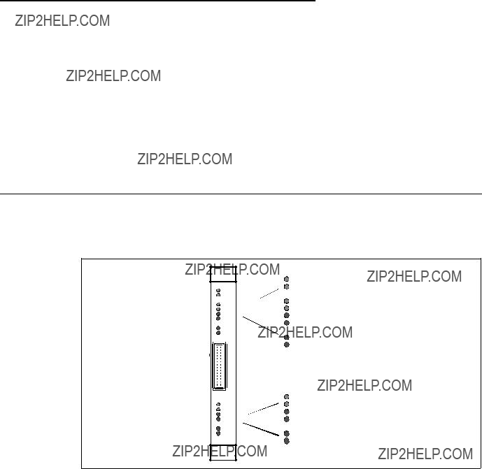
Appendix C. Hardware and Software Information
Appendix C gives an overview of the LEDs on the front panel of the SP Switch Adapter card and shows tables with the meaning of the LEDs??? blinking patterns.
A diagram of the chip interconnections on a TBS Switch Board is provided for a quick reference in helping you to find out the correct Switch port numbers or the correct jack.
You will get some information about updating the IBM 9077 software and how to get updates.
C.1 The Front Panel of the SP Switch Router Adapter Card - Operational
Figure 72 shows the front panel of the Switch Router adapter:
.
PWR ON 3V
RX HB
RX ST0
RX ST1
RX ERR
MD RCV
SW XMIT
TX HB
TX ST0
TX ST1
TX ERR
MD XMIT
SW RCV
Figure 72. Front Panel of the SP Switch Router Adapter Card with LEDs

C.2 SP Switch Router Adapter Media Card LEDs
LED activities during operations are listed in Table 52 on page 296 and Table 53 on page 296. LED activities during bootup are described in Table 54 on page 297.
Table 52. SP Switch Router Adapter Media Card LEDs
296 IBM 9077 SP Switch Router: Get Connected to the SP Switch

C.3 SP Switch Router Adapter Media Card - Bootup
Table 54 shows the settings for the Switch Router Adapter Media Card LEDs during bootup.
Table 54. SP Switch Router Adapter Media Card LEDs During Bootup

C.4 Connectors and Receptacles for Different Media
Table 55 gives you a comprehensive overview of all the supported cables and connectors for the various media cards.
Table 55. Media Card Cables and Connectors
C.5 Chip Interconnection on the TBS Board
Figure 73 on page 299 is taken from the Redbook RS/6000 SP: Problem Determination Guide,
298 IBM 9077 SP Switch Router: Get Connected to the SP Switch
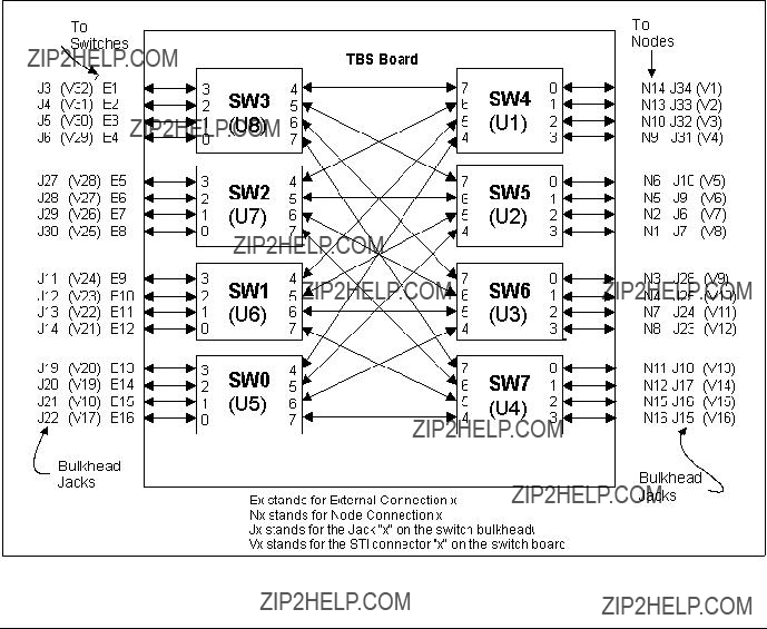
Figure 73. The SP Switch Board
C.6 Updating Router Software
This part provides general information about obtaining and installing new operating software (hereafter referred to as machine code) for the SP Switch Router.
C.6.1 The SP Switch Router as an IBM Product
As is noted in this Redbook, the SP Switch Router is based on a product from Ascend Communications, Inc. IBM customers order and receive the SP Switch Router from IBM. IBM provides all support for this product for IBM customers.
SP Switch Routers are delivered with the current level of machine code already installed. Customers who wish to upgrade to new releases of the machine code should contact their IBM representative.
C.6.2 Obtaining New Machine Code
New releases of the machine code must be obtained from the IBM FTP server: service2.boulder.ibm.com.
You are prompted for the SP Switch Router customer ID and password when you ftp to this server.
Although a new release of the machine code will correspond to an Ascend release of GRF code, only the IBM version of the code will work on the SP Switch Router. Do not try to use GRF code releases obtained from the Ascend FTP site on the SP Switch Router.
Instructions on how to download new releases from the FTP site and install them are included in the Release Notes provided with each release. Be sure to use the "binary" file transfer type.
C.6.3 Support for Code Installation
The Release Notes are posted on the SP Service and Support web site when a new release becomes available. As this is written, the starting page for the SP Service and Support web site is: http://www.rs6000.ibm.com/support/sp. Look for 9077 ???SP Switch Router??? information in the ???Service status??? pages.
C.6.4 Sample Steps to Upgrade the System Software
Follow the steps below:
1.Log on as root and start the UNIX shell: super> sh
2.Change directory:
#cd /usr/nbin
Then, ftp to the IBM server:
# ftp service2.boulder.ibm.com
ftp>
Enter the SP Switch Router customer ID and password as requested.
3. Now change to the /releases directory:
300 IBM 9077 SP Switch Router: Get Connected to the SP Switch
ftp> cd releases
ftp> cd A1_4_6
ftp> cd patches
ftp> cd A1_4_6_4
4.Set the file format and download the files:
ftp> bin
ftp> get grf_update ftp> get RN1_4_6_4.pdf ftp> get RN1_4_6_4.txt ftp> quit
5.Change the script permissions:
#chmod 755 grf_update
6.Install the script:
#grsite
7.Read the documentation with an appropriate reader command (acroread for the pdf file, more or vi for the txt file)!
8.Run the script:
#./grf_update
For a sample execution of the grf_update script, refer to Appendix C.6.5, ???Sample Execution of grf_update Script??? on page 301.
9.To verify the installation, use this command to check that the directed broadcast setting is now one of the sysctl executables:
# sysctl net.inet.ip.fwdirbcast net.inet.ip.fwdirbcast = 1
Note: Be prepared, that grf_update will reboot the SP Switch Router!
C.6.5 Sample Execution of grf_update Script
Here is a sample transcript of a session in which the grf_update script first upgrades a GRF 1600 system (testbox.site.com) that is currently running A_1_4_6,boston to 1.4.6.ibm,default, and then installs the 1.4.6.4.ibm patch release file on the system.
# grf_update
IBM GRF upgrade: testbox.site.com - Thu Apr 16 09:28:14 CDT 1998
This script will upgrade the router system software to
release 1.4.6.ibm and/or install the 1.4.6.4 directed partial release patch file on testbox.site.com.
This script REQUIRES:
- Ftp access to service2.boulder.ibm.com from testbox.site.com.
-Approximately 30MB of disk space in /flash. Please be aware:
-testbox.site.com will be REBOOTED if any system software and/or patch file is installed.
Please take a moment to ensure that the requirement(s) are met and that testbox.site.com can be rebooted at this time.
Continue with upgrade? (y/n): y
Release: currently running A_1_4_6,boston. Upgrade needed to 1.4.6.ibm,default
Checking for 1.4.6.ibm system release files. testbox.site.com will be upgraded using files from service2.boulder.ibm.com.
Loading 1.4.6.ibm release files. Connected to service2.boulder.ibm.com. get 1.4.6.ibm.TAR.gz
local: 1.4.6.ibm.TAR.gz remote: 1.4.6.ibm.TAR.gz 226 Transfer complete.
get 1.4.6.ibm.root.gz
local: 1.4.6.ibm.root.gz remote: 1.4.6.ibm.root.gz 226 Transfer complete.
get Addendum.pdf
local: Addendum.pdf remote: Addendum.pdf 226 Transfer complete.
get RN1_4_6.pdf
local: RN1_4_6.pdf remote: RN1_4_6.pdf 226 Transfer complete.
Performing grwrite. Please wait. Performing grfins. Please wait. Device /dev/wd0a mounted on /flash. Device /dev/wd0a unmounted.
The next release version after rebooting will be: 1.4.6.ibm,default
Patch File: currently running 1.4.6. Need 1.4.6.4 Patch File. Loading 1.4.6.ibm patch release file.
Connected to service2.boulder.ibm.com.
get 1.4.6.ibm,default.site.TAR.gz 1.4.6.ibm,default.site.TAR.gz local: 1.4.6.ibm,default.site.TAR.gz remote: 1.4.6.ibm,default.site.TAR.gz
226 Transfer complete. get RN1_4_6_4.pdf
local: RN1_4_6_4.pdf remote: RN1_4_6_4.pdf 226 Transfer complete.
Loading 1.4.6.4 bsd kernel from 1.4.6.ibm,default.site.TAR.gz.bsd tar: ustar vol 1, 20 files, 3645440 bytes read.
Directed Broadcast: already enabled. No need to modify /flash/etc.1.4.6.ibm,default/rc.local.
The directed bcast will be enabled after the GRF reboots.
302 IBM 9077 SP Switch Router: Get Connected to the SP Switch
To temporarily disable the directed bcast setting later on, use:
# sysctl
To verify that the bcast setting is one of the sysctl executables, use:
# sysctl net.inet.ip.fwdirbcast
IBM GRF upgrade: testbox.site.com is
Next Revision: 1.4.6.ibm Version: default
Patch Revision: 1.4.6.4.ibm
WARNING: testbox.site.com will now be REBOOTED to complete the upgrade. 10 9 8 7 6 5 4 3 2 1
Continuing ...
Shutdown NOW! shutdown: [pid 5524]
*** FINAL System shutdown message from netstar@testbox.site.com ***
System going down IMMEDIATELY
System shutdown time has arrived
Connection closed by foreign host.
304 IBM 9077 SP Switch Router: Get Connected to the SP Switch

Appendix D. Special Notices
This publication is intended to help IBM customers, Business Partners, IBM System Engineers and other RS/6000 SP specialist who are involved in SP Switch Router (IBM 9077) projects, including education of RS/6000 SP professionals responsible for installing, configuring, and administering SP Switch Router. The information in this publication is not intended as the specification of any programming interfaces that are provided by POWERparallel System Support Programs. See the PUBLICATIONS section of the IBM Programming Announcement for POWERparallel System Support Programs for more information about what publications are considered to be product documentation.
References in this publication to IBM products, programs or services do not imply that IBM intends to make these available in all countries in which IBM operates. Any reference to an IBM product, program, or service is not intended to state or imply that only IBM???s product, program, or service may be used. Any functionally equivalent program that does not infringe any of IBM???s intellectual property rights may be used instead of the IBM product, program or service.
Information in this book was developed in conjunction with use of the equipment specified, and is limited in application to those specific hardware and software products and levels.
IBM may have patents or pending patent applications covering subject matter in this document. The furnishing of this document does not give you any license to these patents. You can send license inquiries, in writing, to the IBM Director of Licensing, IBM Corporation, 500 Columbus Avenue, Thornwood, NY 10594 USA.
Licensees of this program who wish to have information about it for the purpose of enabling: (i) the exchange of information between independently created programs and other programs (including this one) and (ii) the mutual use of the information which has been exchanged, should contact IBM Corporation, Dept. 600A, Mail Drop 1329, Somers, NY 10589 USA.
Such information may be available, subject to appropriate terms and conditions, including in some cases, payment of a fee.
The information contained in this document has not been submitted to any formal IBM test and is distributed AS IS. The information about
information or the implementation of any of these techniques is a customer responsibility and depends on the customer???s ability to evaluate and integrate them into the customer???s operational environment. While each item may have been reviewed by IBM for accuracy in a specific situation, there is no guarantee that the same or similar results will be obtained elsewhere. Customers attempting to adapt these techniques to their own environments do so at their own risk.
Any pointers in this publication to external Web sites are provided for convenience only and do not in any manner serve as an endorsement of these Web sites.
Any performance data contained in this document was determined in a controlled environment, and therefore, the results that may be obtained in other operating environments may vary significantly. Users of this document should verify the applicable data for their specific environment.
Reference to PTF numbers that have not been released through the normal distribution process does not imply general availability. The purpose of including these reference numbers is to alert IBM customers to specific information relative to the implementation of the PTF when it becomes available to each customer according to the normal IBM PTF distribution process.
The following terms are trademarks of the International Business Machines Corporation in the United States and/or other countries:
The following terms are trademarks of other companies:
Java and HotJava are trademarks of Sun Microsystems, Incorporated.
Microsoft, Windows, Windows NT, and the Windows 95 logo are trademarks or registered trademarks of Microsoft Corporation.
PC Direct is a trademark of Ziff Communications Company and is used by IBM Corporation under license.
306 IBM 9077 SP Switch Router: Get Connected to the SP Switch
Pentium, MMX, ProShare, LANDesk, and ActionMedia are trademarks or registered trademarks of Intel Corporation in the U.S. and other countries.
UNIX is a registered trademark in the United States and other countries licensed exclusively through X/Open Company Limited.
Other company, product, and service names may be trademarks or service marks of others.
Special Notices 307
308 IBM 9077 SP Switch Router: Get Connected to the SP Switch
Appendix E. Related Publications
The publications listed in this section are considered particularly suitable for a more detailed discussion of the topics covered in this redbook.
E.1 International Technical Support Organization Publications
For information on ordering these ITSO publications see ???How to Get ITSO Redbooks??? on page 311.
???Technical Presentation for PSSP 2.3,
???Technical Presentation for PSSP 2.4,
???RS/6000 SP: Problem Determination Guide,
E.2 Redbooks on
Redbooks are also available on
E.3 Other Publications
These publications are also relevant as further information sources:
???RS/6000 SP: Administration Guide Version 2 Release 4,
???RS/6000 SP: Installation and Migration Guide Version 2 Release 4,
???RS/6000 SP: Diagnosis and Messages Guide Version 2 Release 4,
???RS/6000 SP: Command and Technical Reference Version 2 Release 4,
???RS/6000 SP: Maintenance Information Volume 1 Installation and Customer Engineer Operations,
???RS/6000 SP: Maintenance Information Volume 2, Volume 3,
???RS/6000 SP Planning Volume 1
Hardware and Physical Environment,
???GRF Configuration Guide 1.4,
???GRF Reference Guide 1.4,
???GRF 400/1600 Getting started 1.4,
???SP Switch Router Adapter Guide for 1.4,
310 IBM 9077 SP Switch Router: Get Connected to the SP Switch

How to Get ITSO Redbooks
This section explains how both customers and IBM employees can find out about ITSO redbooks,
This information was current at the time of publication, but is continually subject to change. The latest information may be found at http://www.redbooks.ibm.com/.
How IBM Employees Can Get ITSO Redbooks
Employees may request ITSO deliverables (redbooks, BookManager BOOKs, and
???Redbooks Web Site on the World Wide Web http://w3.itso.ibm.com/
???PUBORDER ??? to order hardcopies in the United States
???Tools Disks
To get LIST3820s of redbooks, type one of the following commands:
TOOLCAT REDPRINT
TOOLS SENDTO EHONE4 TOOLS2 REDPRINT GET SG24xxxx PACKAGE
TOOLS SENDTO CANVM2 TOOLS REDPRINT GET SG24xxxx PACKAGE (Canadian users only)
To get BookManager BOOKs of redbooks, type the following command:
TOOLCAT REDBOOKS
To get lists of redbooks, type the following command:
TOOLS SENDTO USDIST MKTTOOLS MKTTOOLS GET ITSOCAT TXT
To register for information on workshops, residencies, and redbooks, type the following command:
TOOLS SENDTO WTSCPOK TOOLS ZDISK GET ITSOREGI 1998
??? REDBOOKS Category on INEWS
??? Online ??? send orders to: USIB6FPL at IBMMAIL or DKIBMBSH at IBMMAIL
Redpieces
For information so current it is still in the process of being written, look at "Redpieces" on the Redbooks Web Site (http://www.redbooks.ibm.com/redpieces.html). Redpieces are redbooks in progress; not all redbooks become redpieces, and sometimes just a few chapters will be published this way. The intent is to get the information out much quicker than the formal publishing process allows.

IBM Redbook Order Form
Please send me the following:
We accept American Express, Diners, Eurocard, Master Card, and Visa. Payment by credit card not available in all countries. Signature mandatory for credit card payment.
313
314 IBM 9077 SP Switch Router: Get Connected to the SP Switch


ITSO Redbook Evaluation
IBM 9077 SP Switch Router: Get Connected to the SP Switch
Your feedback is very important to help us maintain the quality of ITSO redbooks. Please complete
this questionnaire and return it using one of the following methods:
???Use the online evaluation form found at http://www.redbooks.ibm.com
???Fax this form to: USA International Access Code + 1 914 432 8264
???Send your comments in an Internet note to redbook@us.ibm.com
Which of the following best describes you?
What other redbooks would you like to see published?
Comments/Suggestions: (THANK YOU FOR YOUR FEEDBACK!)