1483/1483DSV Display Station
Operator???s Manual
P/N
1483/1483DSV Display Station
Operator???s Manual
P/N

ISSUE/REVISION SCHEDULE
IBM is a registered trademark of International Business Machines Corporation. NetView is a registered trademark of International Business Machines Corporation. Proprinter is a trademark of IBM Corporation.
HP LaserJet Series II is a trademark of
Epson is a trademark of Epson America, Inc.
?? Copyright 1998 by MTX Corporation
This equipment complies with FCC regulations for EMI.
WARNING!
This equipment generates, uses, and can radiate radio frequency energy, and, if not installed and used in accor- dance with the manual, may cause interference to radio communications. It has been tested and found to comply with the limits for a Class A computing device pursuant to Subpart J of Part 15 of FCC Rules, which are designed to provide reasonable protection against such interference when operated in a commercial environment. Operation of this equipment in a residential area is likely to cause interference, in which case users, at their own expense, will be required to take whatever measures may be neces- sary to correct the interference.


Table of Contents
Page


Chapter 1. Introduction
The 1483 and the 1483DSV Enhanced Function Display Stations (hereafter referred to as the 1483) are ergonomically designed data entry display stations that offer a wide range of functions and applications. The 1483 can be used with a color monitor or a monochrome monitor. Each monitor has five selectable screen sizes (see the table below).
The only difference between the 1483V and the 1483DSV models is the operation in split screen mode. See the appropriate chapter description for mode of operation.
With a monitor that also meets the standard, the 1483 meets ISO 9241 Part 3 requirements.
This manual describes the 1483, identifies controls and operating procedures, and presents diagnostic and maintenance procedures that you can perform. The manual also introduces you to the 1483???s data entry and editing procedures.
As part of a system configuration, the 1483 can transmit and receive data from a central processor unit (CPU) via the attaching controller. You enter or change information on a keyboard that resembles a typewriter. Entered data is simultaneously displayed as alphanumeric characters and symbols on the screen.You can use Function keys to transmit entered data to the CPU or to recall data from the CPU to the screen. The unit can be configured for up to four screen sizes.
Hardware within the display station processes data during transmit and receive operations. Attachment of a coax printer via the controller or an optional local screen printer enables you to generate hard copy of all data displayed on the screen.
Standard Features
The 1483 can be attached to any of the following control units or their
???Telex 076 Control Unit
???Telex 174 Control Unit
???Telex 274 Control Unit
???Telex 276 Control Unit/Display Station
???MTX/MTC 1174 Network Controller

Introduction
???Memorex Telex 1274 Control Unit
???Memorex Telex 1374 Control Unit
???Memorex Telex 2374 Control Unit
???Memorex 2274 Control Unit
???IBM 3174 Control Unit
???IBM 3276 Control Unit Display Station
???IBM 3274 Control Unit or
???IBM 4321 Processor by way of its Display Printer Adapter
???IBM 4331 Processor by way of its Display Printer Adapter
???IBM 4361 Processor by way of its Display Printer Adapter
???IBM 470X Control Units
In addition, the 1483 display station has the following standard features:
Full Screen Menus ??? The full screen menus offer simplicity and ease of use for all setup functions. You can choose between English, French, German, Spanish, and Italian for menu display.
Color Display ??? The 1483???s super VGA color monitor can be set to one of the following color options:
???2 color (green and white)
???4 color (green, white, blue, and red)
???4 color programmable
Reverse Video ??? The Reverse Video feature is supported on
Intensity Control ??? With the 1483???s
Overscan ??? Ergonomic feature that removes the black border around the display area. Available for use with 14- and
Decimal/Hex/Binary Calculator ??? A Decimal/Hexadecimal/Binary calculator that offers convenience to programmers, systems analysts, and others who need to work in decimal, hexadecimal, or binary is available. With the import feature, you can copy the value from the current cursor position on the coax screen to the Results field in any of the calculators. With the decimal calculator, you can set from 0 through 9 decimal places.
Electronic Security Lock ??? If enabled, requires the entry of a
Introduction
Password Protection
Selectable Vertical Refresh Rate ??? The 1483 is designed for use with a super VGA (SVGA) monitor. When attached to a color SVGA monitor, three modes are possible, 72 Hz mode (the default), 60 Hz mode, and 75 Hz mode.
Country Extended Code Page ??? When attached to a properly configured controller, the 1483 supports Country Extended Code Page.
Mono/Dual Case Mode ??? Allows you to specify all uppercase character entry or upper- and lowercase character entry.
Mark Unprotected Field Indicator ??? The 1483 provides a menu option that activates the Mark Unprotected Field indicator. When activated, a dot, a double dot, an underscore, an overscore, or a box is displayed in each unprotected field on the screen. This is particularly useful in data entry environments where fields of data are being entered.
Row/Column ??? Displays the current cursor location on the operator status row.
Switchable Screen Formats ??? The 1483 supports four screen sizes (up to 3564 characters) that you can select from setup menus. The controller to which the 1483 attaches must be configured to support the screen size used.
Partitioning ??? When the controller supports this function, you can use the cursor positioning keys to scroll vertically through a presentation space designated by the host.
Auto Screen Cutoff ??? Automatically blanks the screen, leaving only the operator status line and the cursor displayed after a specified length of time (5, 10, 15, 20, . . . 55, 60 minutes) has passed during which no key is pressed and no data is written to the screen by the host.
Screen Standby ??? When used with compatible monitors, it allows screens to go to black and reduce monitor power consumption. It also allows nearly instant screen display after a keystroke. This meets the TCO StandBy requirement of <30w.
1483 Split Screen ??? Displays two MOD 2 sessions simultaneously. The top session is 24 full lines and the bottom session is a scrollable
1483DSV Split Screen ??? The 1483 DSV displays two full MOD 2, 3, or 4 sessions simultaneously side by side. Marking and pasting data is supported between the two sessions.
Power Down ??? Automatically cuts power to the monitor after the specified number of minutes (after Auto Screen Cutoff) during which no key is pressed and no data is written to the screen by the host. Meets TCO
Numeric Lock ??? Allows a field to be defined to accept only numeric characters, and the Period, Minus, and Dup keys. The comma may be substituted for the period on some international keyboards.

Introduction
Audible Alarm ??? Sounds when a character is entered in the
Tilt/Rotate Capability ??? Allows the display to be tilted over 20 degrees of arc and rotated a full 180 degrees for viewing ease.
Host Addressable Print ??? Lets the host print to a printer attached directly to the 1483.
Local Screen Print ??? Allows you to make a hard copy of displayed text using the screen print function. You can specify print area, print quality, line density, and print pitch.
Plain Printer Support ??? By selecting the plain or generic printer for the printer type and manually entering printer escape codes, you can customize the 1483 to support a wide range of ASCII printers.
Landscape and Portrait Printing ??? The 1483 supports both landscape and portrait paper orientation when printing on an HP LaserJet or compatible printer.
Print All User Setup Menus ??? You can keep a record of the setup defaults you set by printing the online and offline user setup menus.
Keystroke Record/Pause/Playback ??? Enables you to store keystroke sequences under each of the F or PF keys. A maximum of 7000 keystrokes can be stored in nonvolatile memory and can be played back at any time. During playback, a pause feature allows you to perform normal operations before resuming playback. Calculator keystrokes can be recorded and played back.
Record/Playback Security Mode ??? Enables you to either disable the Record/Play feature or to inhibit playback in a protected field.
Response Time Monitor ??? Supports
Modifiable Keyboard ??? Using the Keyboard Definition mode, you can modify the keyboard layout by interchanging and adding keycaps. The control unit must be properly configured to support this feature.
Entry Assist Function ??? Facilitates the creation and editing of text such as memos, letters, and documents. Refer to Chapter 5 for Entry Assist operation information. The attached controller must support this function.
Print Trim Function ??? Allows for printing only the selected portion of the screen when making a local screen print.
Auto Skip After Local Print ??? Enables the printer to automatically advance a selected number of lines after it performs a local or host addressable print.
Stationary or Movable Rule Function ??? Enables you to set a horizontal and/or a vertical line at the cursor position to facilitate construction and use of tables.
Cursor Speed Selection ??? You can choose from three horizontal cursor speeds of slow, medium, and fast.

Introduction
Repeat Delay ??? You can select a short, medium, or long time interval before starting the continuous display of characters on autorepeat keys.
Serial Number Entry ??? In Offline mode, you can verify or enter the display station serial number. This information, along with the Product ID, is stored in the display station???s nonvolatile memory and is available to be read by the control unit for systems statistics gathering by NetView. The control unit to which the display station is attached must support this function.
Extended Vital Product Data ??? From the Offline Test menu, you can review a
Variable Lines per Page ??? You can select from 1 through 127 lines per page.
Light Pen ??? Optional feature that lets you select data from a display panel by pointing to it with a

Chapter 2. Customer Installation
This chapter lists the physical statistics and environmental requirements for the 1483. It also describes the procedures for setting up the display station and performing a preliminary operating test.
The 1483 is designed to be installed by the user. No special tools are required.
Physical Statistics
Refer to the owner???s manual that comes with your monitor for the monitor???s specifications.
Environmental Requirements
For units operating at

Customer Installation
For units operating at
The power cable required for international units is an 18/3 AWG, type SJT cable
The installation site must provide a properly wired and grounded power outlet. Circuits connected to air conditioners and devices that generate significant transient electrical noise should be avoided.
Electrostatic discharge in the vicinity of the unit should be minimized by avoiding high resistance floor material and carpeting that does not have antistatic properties, by avoiding the use of plastic seats and covers, and by avoiding low humidity levels. The unit should be located away from areas that generate electromagnetic interference (for example, transformers, power distribution panels, welding equipment, motors, transmitters). Do not put the unit next to fluorescent lights. The 1483 should not be installed where the atmosphere contains corrosive elements that can damage the unit.
Do not run the cable in areas that produce electromagnetic interference (for example, near transformers, switching equipment, welding equipment, power distribution panels, and under carpets where vacuum cleaning is done). Also, do not roll heavy equipment over the cable.
Inspecting the Packages
Before you unpack the Display element, Logic element, and Keyboard element, inspect the carton for physical damage.
If the exterior package is damaged, contact your local MTX Inc. sales office or distributor. Also contact the carrier to request examination of the damage. The carrier is required to complete and sign a damage report form.
Note: To report damage, customers in the Continental US should call MTX Inc.
If the package is not damaged, remove the package contents.
Customer Installation
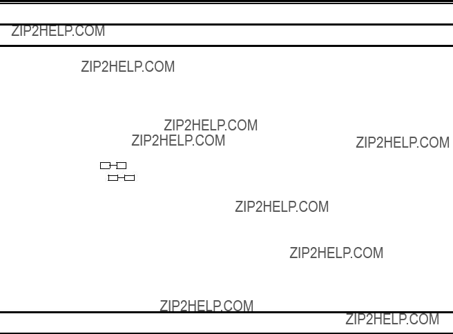
Setting Up the Display Station
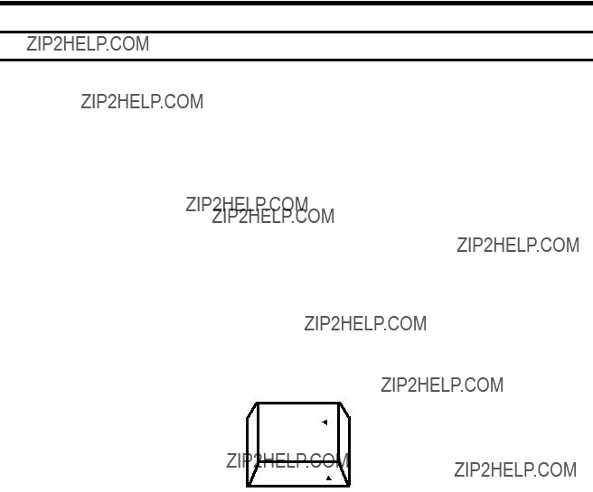
1)Place the Display element on top of the Logic element and place both within connecting distance of an appropriate AC power outlet.
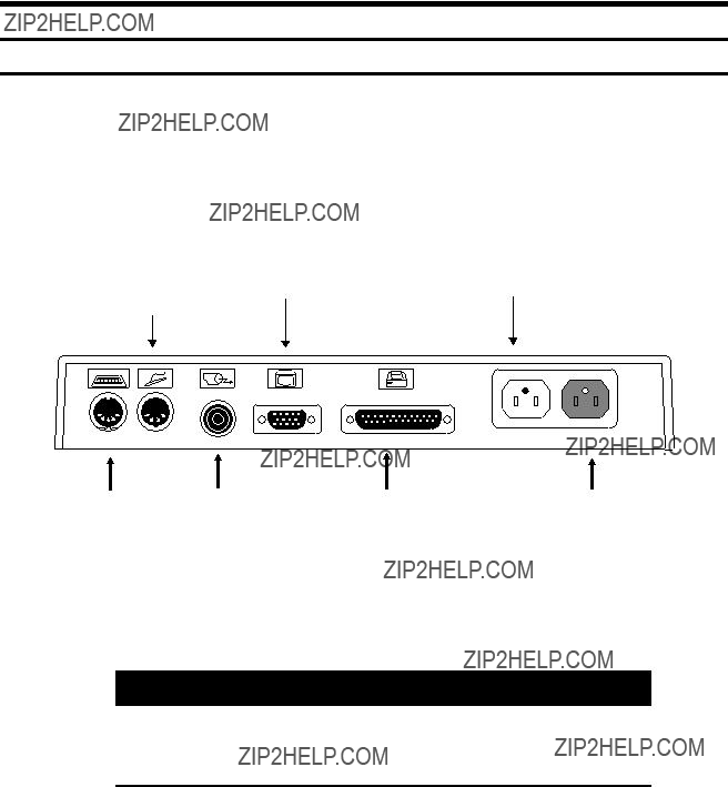
2)Place the keyboard in front of the Logic element. Pull out the feet underneath the keyboard to adjust it to a higher setting, if desired. Insert the keyboard plug into the keyboard connector on the back of the Logic element (Figure
Figure
3)Refer to the owner???s manual that comes with your monitor for instructions on how to attach the monitor cable.
Warning
If the power rating on the Logic element is not equal to or greater than the power rating on the Display element, do not plug the monitor cable into the Logic element. Plug it into a wall receptacle.
4)For the host addressable or local screen print function, a printer connector is located on the back of the Logic element (Figure
Customer Installation
5)Make sure that the
There are two AC power cables. Follow the instruction in Step 6 to install one power cable and follow the instructions in Step 7 to install the other power cable.
6)Attach one end of the monitor AC power cable to the AC power cable connector on the back of the Display element (see the booklet that came with the Display element for the location of the AC power connector) and the other end to the AC power connector on the back of the Logic element (Figure
7)Plug one end of the power cord into the AC connector on the back of the Logic element (Figure
Installing the Optional Light Pen
Follow these steps to install the optional light pen:
1)Remove the light pen and its holder from the protective wrap.
2)Insert the light pen???s cable connector into the
3)Peel the protective cover from the light pen holder???s mounting surface.
4)Mount the light pen holder on the side of the display station.
5)Measure the amount of cord needed for the light pen to reach from the holder to any point on the screen. Leaving this amount free, place the light pen cord into the cord retainers.
Note: The light pen is not supported in Split Screen mode.
Connecting the Display Station to the Host Systems
Connect the display station to the host or to a controller with a coax cable up to 1500 meters (4920 feet) long, or a
(coax length) + (5 x
Follow these steps to connect the 1483 to the host system or to a controller:
1) Locate the coax or

Customer Installation
2)Align the end of the connector cable with the Coax connector that is on the back of the Logic element (see Figure
Setting Up the Display Screen
The 1483 is designed to operate with color SVGA and/or VGA monitors, or monochrome SVGA or VGA monitors. Depending on whether you have a color or monochrome monitor, follow one of the procedures below to set up the screen before you turn power on the first time.
Color Monitor
1)Determine the type of monitor (SVGA, VGA, or combined SVGA/VGA) you have. You will set the monitor to operate in SVGA or VGA mode.
2)Press and hold one of the following function keys while you turn the
???F1 ??? Sets the monitor to color SVGA mode.
???F2 ??? Sets the monitor to color VGA mode (default).
???F7 ??? For multifrequency monitors that can operate up to 42 KHz, sets the vertical refresh rate to 75 Hz.
Monochrome Monitor
1)Determine whether you have a
2)Press and hold one of the following function keys while you turn the
???F3 ??? Sets the monitor to
???F4 ??? Sets the monitor to
???F5 ??? Sets the terminal to
???F6 ??? Sets the monitor to
Customer Installation
Conducting the Preliminary Operating Test
1)Ensure that the system control unit is powered on and operational.
2)Turn the Power On/Off switch to Off (O) .
3)Set the
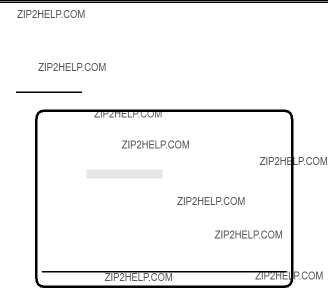
4)Continue to hold the space bar down until a screen like the one in Figure
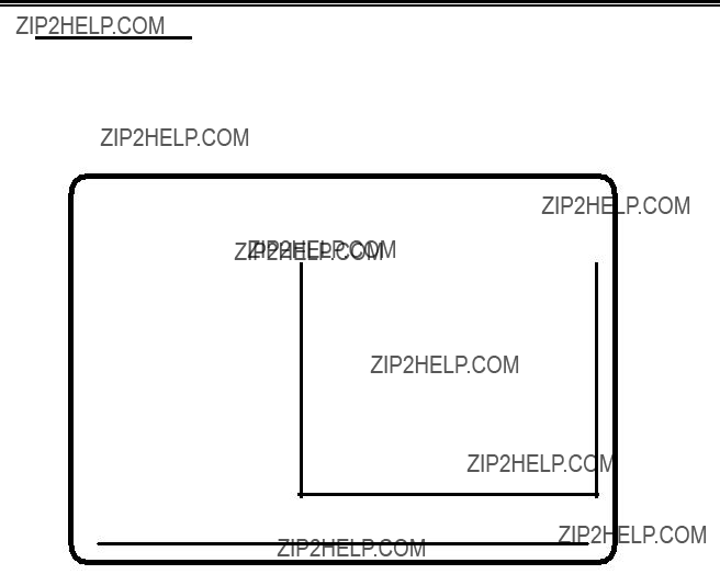
Offline Test Menu
Select One of the Following
User Menus
System Manager Menus
User Defined Data
Product ID 1483V (c)1995
Go Online
Figure
5)If the display station is designated to operate with settings other than the default modes, see ???Offline Test Menu??? on Page 3- 5 for a description of the Offline Setup menus to change the modes. Obtain the settings designated for the display station from the system operator. The controller to which the display station attaches must be configured to support the settings selected. When the display station is set correctly, it is ready to go online. Press the Reset key to display the cursor in the upper left corner of the screen and the operator status row at the bottom.
6)If the screen does not have the cursor in the upper left corner and the operator status row at the bottom, see Chapter 7, ???Problem Determination and Maintenance.???
7)Installation of the display station is now complete. Certain settings may be changed while online. See Figure

Chapter 3. Setup Menus, Controls,
and Indicators
This chapter describes the display controls, keyboard controls, and display indicators on the 1483 and its attached keyboard.
Display Controls
Refer to the installation booklet that comes with your Display element for an illustration of the locations of the Brightness, Contrast, and other controls. Any controls not on the display station are regulated from the setup menus and are described in the sections on Online and Offline Setup mode.
Keyboard Operation Modes
You can select either of two keyboard operation modes, Emulation mode or Native mode. The default setting is to emulate an IBM 3278
With Native mode selections, Keyboard Definition mode is supported.
Emulation Mode
Emulation mode can be used with a
Setup Menus, Controls, and Indicators
Native Mode
Native mode causes the display station to provide to the attached controller unconverted keyboard scan codes which are defined by the controller depending on how it is configured. Native mode is available on the
???MTX/MTC 1174 Network Controller
???Memorex Telex 1274 Control Unit at firmware release level 11.0 or higher
???IBM 3174 Control Unit
???IBM 3274 Control Unit at configuration support D microcode release level 63.0 or higher.
To use Native mode with a
???MTX/MTC 1174 Network Controller
???Memorex Telex 1274 Control Unit at firmware release 16.0 or higher (if the 1274 supports Multiple Logic Sessions, firmware release 53.0 or higher)
???Memorex Telex 1374 Control Unit
???IBM 3174 Control Unit
???IBM 3274 Control Unit at configuration support D microcode release level 65.0 with RPQ # 760825.
The control unit to which the 1483 is attached also must be configured to support Native mode.
Keyboard Definition Mode
In Native mode, the 1483 supports Keyboard Definition mode. Keyboard Definition mode enables you to modify the keyboard layout by using the control unit???s Keyboard Definition Utility. The attached control unit must be configured properly to support this feature.
Setup Menus, Controls, and Indicators
Keyboard Controls
This section describes keys on the
Alt
Shift
Reset
Change Screen ??? Press the Change Screen key to toggle between sessions. The Change Screen key does not work with all controllers. In Emulation mode, if the Change Screen key does not function, press and hold the Alt key while you press the Insert key. If the Change Screen key does not function in Native mode, press and hold the Alt key while you press the PA2 key.
PA3 ??? The PA3 key is an additional function key. It does not work with all controllers. The PA3 key does not function in Emulation mode.
Alt Function
 Key Face
Figure
Note: On some international keyboards, the Alt function is located on the top right quadrant of the key.

Setup Menus, Controls, and Indicators
Each keyboard type contains autorepeat keys that repeat their functions as long as they are pressed. The autorepeat keys include all keys that enter alphabetic, numeric, or symbol characters, the space bar, all keys that assign or move the cursor position, and the following
???Field Mark (Data Entry keyboards only)
???Duplicate (Data Entry keyboards only)
???Skip (Data Entry keyboards only)
Offline Setup Mode
All the controls described in ???Online Setup Mode??? except for the options on the Online Printer menu (see Page
???Screen Size
???Partition
???Keyboard Type
???Numeric Lock
???Keyless Security Lock
???Printer Type
???Host Addressable Print
???Offline Tests
???Screen Centering
???Password Protection
???Serial Number
???Play/Record Options
???Reset NVRAM
Check with the system operator before changing any of these control values.
To enter Offline Setup mode, perform one of the following steps:
From the Online Miscellaneous menu, highlight Go Offline and press the Enter key. The following message is displayed in blinking characters to warn you that data may be lost:
Data May Be Destroyed
Hit ENTER to Continue RESET to Abort
Setup Menus, Controls, and Indicators
Press Reset to remain online with no loss of data, or press Enter to go offline.
Or
With the display power off, press and hold down the space bar and simultaneously turn on the display station.
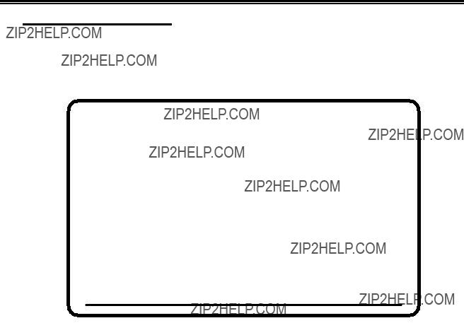
After either step is performed, the Offline Test menu (Figure
Offline Test Menu
Offline Test Menu
Select One of the Following
User Menus
System Manager Menus
User Defined Data
Product ID 1483 (c) 1993
Go Online
Figure
Use the Up and Down Arrow keys to highlight User Menus on the Offline Test menu and press the Enter key. The Offline Screen menu is displayed (Figure
Offline Test Menu Selections
1)The User Menus selection displays offline menus for operator setup. Offline menus include all Online functions as well as functions that can only be selected offline.
2)The System Manager Menus selection displays a menu for system setup by the system manager. See Page

Setup Menus, Controls, and Indicators
3)The User Defined Data selection displays a panel of Extended Vital Product Data information. This panel is for information only. Extended Vital Product Data cannot be entered or changed from the 1483. Extended Vital Product Data is entered from the controller. See the documentation for your controller for information about entering and changing Extended Vital Product Data.
4)The Go Online selection puts the display station online for normal operation.
User Menus
To display the Offline Menu screens, highlight User Menus on the Offline Test menu and press the Enter key. If password protection is enabled (see Page
Press the Left or Right Arrow key to highlight
S c re e n , C u r s o r, Ke y b o a r d , P r i n t e r, Miscellaneous, or Color (the Color option is displayed only if you have a color monitor) to display other offline user setup menus.
To change menu language:
a)From the Offline Menu screen, press the Right Arrow key four times until Miscellaneous (Divers, Verschiedenes, Miscellanea, Varios) is selected. See Figure
b)Press the Enter key repeatedly until the correct language appears. Languages are English, French, German, Spanish, and Italian.
Note: You can print the offline setup user menus. To print a menu, display the menu on the 1483 screen and press the Print key.
Offline Screen Menu
All of the options in Figure

Setup Menus, Controls, and Indicators
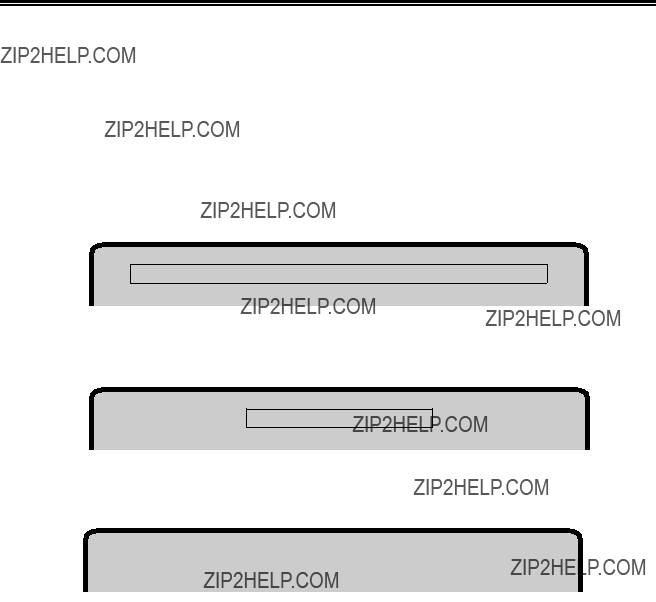
Offline Menu Screen
Use Arrow Keys to choose item
Use ENTER Key to change item
RESET Key Exits
Figure
MONOCASE/DualCase
To select MONOCASE or DualCase mode, highlight MONOCASE/DualCase and press the Enter key to toggle between MONOCASE and DualCase. When MONOCASE is selected, all characters are displayed on the screen as uppercase letters. When DualCase is selected, all characters are displayed as both upper- and lowercase.
Mark Unprotected
When activated, the Mark Unprotected Field indicator displays a selectable symbol in each unprotected field on the screen. This enables you to recognize locations where keystrokes can be entered. To activate the Mark Unprotected Field indicator, highlight Mark Unprotected and press the Enter key to select Yes or No (the default).
Mark Unprotected Field Character (MUP)
To select a Mark Unprotected Field symbol, highlight MUP Character and press the Enter key to display one of the following symbols: dot ( . ), two dots ( .. ), underline ( _ ),
overscore ( ?? ), or character outline box ( 
 ). The default is dot ( . ).
If Mark Unprotected (above) is set to No, your selection for MUP Character is ignored.

Setup Menus, Controls, and Indicators
MUP Overstrikes
With MUP Overstrikes set to Yes, the selected MUP symbol overstrikes the displayed character. With No selected, the displayed character replaces the MUP character. To change the MUP overstrikes option, highlight MUP Overstrikes and press the Enter key to toggle between Yes and No (the default).
If Mark Unprotected (see Page
Row/Column
When Row/Column is turned on, the current row and column position of the cursor is displayed on the operator status row. The indicated position may not be the actual cursor position on the display screen. The numbers indicate the location of the cursor in the actual image that the display station receives from the host system. Highlight Row/ Column and press the Enter key to turn the cursor row/column display On or Off (the default).
Screen Size
To adjust the display screen, highlight Screen Size on the Offline Screen menu and press Enter to cycle through the four possible screen size settings:
???24 X 80 (Mod 2) ??? default
???32 X 80 (Mod 3)
???43 X 80 (Mod 4)
???27 X 132 (Mod 5)
The screen size displayed is the active screen size.
Partition
The partitioning function supported by the display station is completely a host controlled function. The display receives partitioning commands from the host when Partition is enabled on the Offline Screen menu and Native Typewriter is selected on the Offline Keyboard menu (Figure
Reverse Video
The Reverse Video setting enables you to display black characters on a green, amber, or white screen. To set the Reverse Video option, highlight Reverse Video and press the Enter key to toggle between On (white characters on a black screen) and Off (black characters on a white screen). The default setting is On.
Note: The Reverse Video feature is supported on
Setup Menus, Controls, and Indicators
Intensity Control
The Intensity Control setting enables you to determine the area to be highlighted. There are three settings for Intensity Control: Normal (the default), Data only, and Highlight. It is available only on monochrome monitors.
To use the Intensity Control option, you must first set the Reverse Video option On (black characters on an amber, green, or white screen). Highlight Intensity Control and press the Enter key to cycle through the choices: Normal (the default), Data Only, and
Highlight.
Normal ??? The entire background field, data area and nulls, is highlighted.
This is Normal Intensity.
Data only ??? The background field, data only, is highlighted.
This is Data Only Intensity.
Highlight ??? The foreground color is highlighted (only the data characters, not the nulls).
This is Highlight Intensity.
Figure
Leaving the Offline Screen Menu
To leave the Offline Screen menu, use the Left and Right Arrow keys to highlight another offline setup menu, or press the Reset key to leave Offline Setup mode and display the Offline Test menu.

Setup Menus, Controls, and Indicators
Offline Cursor Menu
To display the options on the Offline Cursor menu, use the Left and Right Arrow keys to highlight Cursor on any offline setup menu and press the Enter key. The Offline Cursor menu is displayed (Figure
All of the options in Figure
Offline Menu Screen
Use Arrow Keys to choose item
Use ENTER Key to change item
RESET Key Exits
Figure
Cursor Size
The Cursor Size option enables you to choose an underline cursor ( _ ) or a block cursor (  ). Highlight Cursor Size and press the Enter key to toggle between Block (the default) and Underline.
Cursor Blink
You can select a blinking cursor or a nonblinking cursor by highlighting Cursor Blink and pressing the Enter key to toggle between Off (the default) and On.
Rule Style
You can select the rule style for the rule function. The rule style can be a line ( ??? ), cross ( + ), or bar ( | ). To select a rule style, highlight Rule Style, then press the Enter key to toggle through the choices Line ( ??? ) (the default), Cross ( + ), and Bar ( | ).
To use the rule cursor when you are online, press the Rule key.

Setup Menus, Controls, and Indicators
Stationary Rule
The rule cursor can function as a horizontal or vertical ruler. If you select Stationary for the Stationary Rule, the rule line does not move with the cursor, but remains as an alignment aid for columns or rows. (To relocate the rule line to the current position of the cursor, press the rule key twice.)
If you select Moves for the stationary rule, the rule moves with the cursor.
To set the stationary rule, highlight Stationary Rule and press the Enter key to toggle between Moves (the default) and Stationary.
To use the rule cursor when you are online, press the Rule key.
Rule Color
Note: To use the rule cursor when you are online, press the Rule key.
For color monitors:
The rule can be set to any of the selectable colors. To change the rule color, highlight Rule Color and press the Enter key to cycle through the color options. The rule color you select is displayed on the screen. The color options are:
???C1 (blue) ??? default setting
???C2 (red)
???C3 (pink)
???C4 (green)
???C5 (turquoise)
???C6 (yellow)
???C7 (white)
For monochrome monitors:
The rule can be set to be intensified or normal. Press the Enter key to toggle between
Intensified (the default) and Normal.
Leaving the Offline Cursor Menu
To leave the Offline Cursor menu, use the Left and Right Arrow keys to display another offline setup menu, or press the Reset key to leave Offline Setup mode and display the Offline Test menu.
Setup Menus, Controls, and Indicators
Offline Keyboard Menu
To display the options on the Offline Keyboard menu, use the Left and Right Arrow keys to highlight Keyboard on any offline setup menu and press the Enter key. The Offline Keyboard menu is displayed (Figure
Offline Menu Screen
Use Arrow Keys to choose item
Use ENTER Key to change item
RESET Key Exits
Figure
Alarm Volume
To adjust the audible alarm volume, highlight Alarm Volume and press the Enter key to cycle through the volume choices of Off, 1 (quietest), 2, 3, 4, and 5 (loudest). The alarm sounds each time you press the Enter key (except for Off) so you can check the level of each setting. The default setting is 3.
The alarm sounds when a character is entered in the
Click Enable
When the display station goes online, the keyboard click performs according to how the Click Enable option was last set. After the display station has gone online, the keyboard click can be activated or deactivated by the controller, such as when an ???Input Inhibited??? error occurs. You can also toggle the keyboard click on and off by holding down the Alt key while you press the F24 key.

Setup Menus, Controls, and Indicators
When the display station goes offline, the menu setting for Click Enable is saved. Changes made to the keyboard click by the controller or by the Alt/F24 toggle key combination are not saved when the display station goes offline.
Press the Up or Down Arrow key to highlight Click Enable, then press the Enter key to toggle between Yes and No (the default). Select Yes to make the keyboard click with each keystroke or select No to deactivate the keyboard click.
Click Volume
To adjust the keyboard click volume, highlight Click Volume and press the Enter key to cycle through the volume choices of Off, 1, 2, 3 (the default), 4, and 5.
If Click Enable (see Page
Cursor Speed
To change the horizontal cursor speed, highlight Cursor Speed and press the Enter key to cycle through the choices Slow (the default), Medium, and Fast.
Repeat Delay
You can change the time interval of starting the continuous display of characters on autorepeat keys by changing the autorepeat delay speed control. To adjust the speed delay, highlight Repeat Delay and press the Enter key to cycle through the choices Short, Medium (the default), and Long.
Keyboard Type
Note: Check with the system operator before changing this value.
The Keyboard Type setting enables you to select a keyboard/display configuration. The system operator will know in which mode the keyboard should operate. The default keyboard type, Native Typewriter, is set at the factory before the 1483 is shipped to you.
The following keyboard types are available:
???Emulate 88 Key KBD ??? Enables a
???Emulate 88 Key
???Native Mode - 00
(Native Mode European Typewriter Keyboard)
???Native Typewriter
(Native Mode US Typewriter Keyboard)

Setup Menus, Controls, and Indicators
???Data Entry Keyboard
(Native Mode Data Entry Keyboard)
???APL Keyboard
(Native Mode APL Keyboard)
???User Define - 01
(Native Mode Typewriter ??? Controller Keyboard Definition Utility required)
???User Define - 02
(Native Mode Typewriter ??? Controller Keyboard Definition Utility required)
???User Define - 03
(Native Mode Typewriter ??? Controller Keyboard Definition Utility required)
???User Define - 04
(Native Mode Typewriter ??? Controller Keyboard Definition Utility required)
???User Define - 01+
(Native Mode Data Entry ??? Controller Keyboard Definition Utility required)
???User Define - 02+
(Native Mode Data Entry ??? Controller Keyboard Definition Utility required)
???User Define - 03+
(Native Mode Data Entry ??? Controller Keyboard Definition Utility required)
???User Define - 04+
(Native Mode Data Entry ??? Controller Keyboard Definition Utility required)
To change the keyboard selection, highlight Keyboard Type on the Offline Keyboard menu and press Enter until the required selection is displayed.
Numeric Lock
Note: Check with the system operator before changing this value.
The Numeric Lock restricts the characters that can be keyed into a designated numeric field.
To enable the numeric lock, highlight Numeric Lock and press the Enter key to toggle the feature On (default value) or Off.
Changing the Keyless Password
You can modify the password for the Electronic Security Lock by doing the following:
1)Move the pointer to the Change KEYLESS Password prompt and press Enter.
2)You are then prompted to input the current password. As each keystroke is input, an * is displayed in the results column. If an incorrect password is input, password prompts are removed. To retry, press Enter to restore the prompt.
Note: The default password as shipped or after RESET NVRAM is OFF. OFF disables the electronic keylock when online.

Setup Menus, Controls, and Indicators
3)If you entered the password correctly, you are prompted for a new password. The next three keystrokes are taken as the new password.
4)You are then prompted to reenter the new password to verify the change. When the third keystroke is entered, all of the password prompts are removed. If the keystrokes do not match, the password is not changed.
Leaving the Offline Keyboard Menu
To leave the Offline Keyboard menu, use the Left and Right Arrow keys to display another offline setup menu, or press the Reset key to exit Offline Setup mode and display the Offline Test menu.
Offline Printer Menu
To display the options on the Offline Printer menu, use the Left and Right Arrow keys to highlight Printer on any offline setup menu and press the Enter key. The Offline Printer menu is displayed (Figure
Offline Menu Screen
Use Arrow Keys to choose item
Use ENTER Key to change item
RESET Key Exits
Figure

Setup Menus, Controls, and Indicators
Highlight Printer on the Offline Printer menu and press Enter to cycle through these choices:
???4201 Proprinter (IBM Proprinters II and III)
???4202 Proprinter (IBM Proprinters II and III XL)
???1173
???COAX
???1301
???1302
???1201 (default setting)
???1202
???1808
???LaserJet (HP LaserJet Series II)
???ThinkJet (HP ThinkJet)*
???DeskJet (HP DeskJet 500)*
???FX1050 (Epson)*
???LQ1050 (Epson)*
???4207 (IBM Proprinter X24E)
???4208 (IBM Proprinter XL24E)
???5202 (IBM Quietwriter III)
???5204 (IBM Quickwriter)
???4019 (IBM LaserPrinter)
???Plain (generic printer)
*If you select this printer, you must set the DIP or Mode Select switches on the printer. See Appendix A, ???Printer Information,??? for the correct switch settings.
Caution
Use of any printer other than those specified could produce unpredictable results and is neither recommended nor supported.

Setup Menus, Controls, and Indicators
Program Setup Strings for Prints
You can specify print attributes for any supported printer by setting the
Note: Only the following commands are sent to the Plain printer:
???Line feed
???Form feed
???Carriage return
???Backspace
???Spaces for horizontal tabs
When you set a
To set the
Use the Up and Down Arrow keys to highlight a position, then use the Left and Right Arrow keys to cycle through the escape codes (00 through FF). The initial
To set all positions to 00 and disable this feature, press the Clear key.
To leave the Programmable Setup Strings for Prints menu and return to the Offline Printer menu without saving any changes, press the Reset key.
To leave the Programmable Setup Strings for Prints menu and return to the Offline Printer menu with the changes saved, press the Enter key. When you leave the Programmable Setup Strings for Prints menu, the setup strings are sent to the printer.

Setup Menus, Controls, and Indicators
Use UP/DOWN Cursor Keys to select position to change
Use LEFT/RIGHT Cursor Keys to alter data at selected position
Use ENTER Key to make changes and return to previous menu
Use RESET Key to return to previous menu
Use CLEAR Key to set all positions to 00
Figure
Host Addressable Print
The host addressable print feature enables the host to send print requests to the 1483???s attached printer. LU2 (screen) prints are always formatted by the display according to the printer menu selections.
To enable or disable host addressable print, highlight Host Addressable Print and press the Enter key to toggle between Yes (the default) and No. Host addressable print cannot be enabled if an Emulate
Controllers that support host addressable print are the MTX/MTC 1174 Network Controller, Release 7.0 and higher, and the Memorex Telex 1374 Control Unit, Release 6.0 and higher.
Note: The host addressable print feature supports LU1 SCS commands.
If host addressable print is enabled, the Adjusting Line Feed and Adjusting Form Feed options are displayed.
Printer Format Control
The printer format control feature enables the user to specify whether the formatting of LU1 or LU3 will be handled by the display.

Setup Menus, Controls, and Indicators
If you select System, then formatting of LU1 or LU3 will not be handled by the display. In addition, CPI/LPI menu information will not be used to initialize the printer, and there will not be automatic form feed or new line performed by the display.
If you select Terminal, the default, the data for LU1 and LU3 prints will be handled by printer menu selections.
Adjusting Line Feed
You can configure the printer to suppress an automatic line feed by selecting one of the following options:
Suppress automatic line feed when:
Note: In the following options, CR means carriage return, FF means form feed, and NL means new line.
???CR at maximum print position + 1 ??? If you select Yes for this option, when the printer reaches the maximum line position + 1 (the end of the print line), the carriage returns to the beginning of the line without a line feed. The next printed characters will overwrite the current line of printed characters.
If you select No (the default) for this option, when the printer reaches the end of the line, the carriage returns to the beginning of the line and drops down one line.
???FF at print end ??? If you select Yes for this option, the printer does not execute a line feed after a form feed.
If you select No (the default) for this option, the printer executes a line feed after a form feed. Characters printed on the new page begin on the second line.
???NL at maximum print position + 1 ??? If you select Yes for this option, the printer does not execute a line feed if there is a new line command at the maximum print position + 1 (the end of the print line). The printer begins printing on the next line.
If you select No (the default) for this option, when the printer reaches the end of the line, it executes two line feeds.
Adjusting Form Feed
You can configure the printer to adjust the form feed by selecting one of the following options:

Setup Menus, Controls, and Indicators
FF ignored when not in first print position
If you select Yes for this option, a form feed character in the first position or next to the maximum print position is executed while form feed commands in any other positions are printed as blank characters and are otherwise ignored.
If you select No (the default) for this option, all form feed commands are executed.
FF takes position if followed by data
If you select Yes for this option, if the form feed character is not at the end of the print data, a form feed is executed and a blank character is printed in the first position on the next page. Subsequent printing starts in the second position on the new page.
If you select No (the default) for this option, the form feed character is not printed as a blank character and subsequent printing starts in the first position on the new page.
FF at end of print
If you select Yes for this option, the printer ejects the last printed page and subsequent printing begins on the new page.
If you select No (the default) for this option, the last page is not ejected and a line feed is executed. Subsequent printing begins on the new line of the current page.
Transparent
Note: Check with your system manager before changing this option.
If Transparent is set to Coax (3287 emulation), data included in an SCS Transparent Mode command (35H) is printed in the LU1 environment as follows:
???Valid EBCDIC characters are translated and printed normally.
???Invalid EBCDIC characters (SNA character string [SCS] commands) are printed as hyphens.
If Transparent is set to ASCII, all data included in the command is sent through to the printer untranslated. The following setup values are not sent to the printer during initialization:
???Chars/Inch
???Lines/Inch
???Quality
To set the Transparent option, highlight Transparent on the Offline Printer menu, then press the Enter key to toggle between Coax (the default) and ASCII.

Setup Menus, Controls, and Indicators
Printer TRPQs
A collection of printer TRPQs can be accessed from the Offline Printer menu by pressing the F9 (or PF9) key. The TRPQs are software features that permit additional printer controls. The TRPQs are shown below:
To enable any Printer TRPQ, do the following:
1)From the Offline Printer menu, press F9 (or PF9)
Active Print TRPQ numbers appear on the Status line. If no numbers appear, no TRPQs are active.
2)Press the PF key that corresponds to the TRPQ number you want to enable. For example, to enable Printer TRPQ number 3, press the PF3 key.
The number of the enabled TRPQ appears on the status line for three seconds.
To disable a Printer TRPQ, do the following:
1)From the Offline Printer menu, press F9 (or PF9). Active Printer TRPQ numbers appear for three seconds.
2)Press the PF key that corresponds with the number of the TRPQ you want to disable. For example, to disable TRPQ number 4, press the F4 (or PF4) key.
Leaving the Offline Printer Menu
To leave the Offline Printer menu, use the Left and Right Arrow keys to display another offline setup menu, or press the Reset key to leave Offline Setup mode and display the Offline Test menu.
Setup Menus, Controls, and Indicators
Offline Miscellaneous Menu
To display the options on the Offline Miscellaneous menu, use the Left and Right Arrow keys to highlight Miscellaneous on any offline setup menu and press the Enter key. The Offline Miscellaneous menu is displayed (Figure
Offline Menu Screen
Use Arrow Keys to choose item
Use ENTER Key to change item
RESET Key Exits
Figure
Setup Language
You can choose between English (the default), Fran??ais , Deutsch, Espa??ol, and Italiano for the language on the setup menus.
To change the current setting, highlight Setup Language and press the Enter key to cycle through the available settings. As each choice is selected, the menu changes to that language and all menus continue to be displayed in that language until changed again.
Dim Timer
The Dim Timer controls when the Auto Screen Cutoff function takes effect. When this function is set, the screen blanks in a specified number of minutes if the display station does not receive data from the keyboard or a host system. The Dim Style section provides information for which of the two methods of screen blanking is active.
To enable this function, highlight Dim Timer and press the Enter key to cycle through Off (no dim), 5, 10, 15, . . ., 55, 60. The default is 10 minutes.
Note: The Auto Screen Cutoff function does not work while the display station is in Setup mode.

Setup Menus, Controls, and Indicators
Dim Style
When Status Row Only is selected and the display has been inactive for the amount of time set in the Dim Timer, the screen blanks, and only the operator status row and cursor are displayed. The  symbol is displayed on the operator status row. Press the space bar to restore the screen without adding characters. Also, if the host initiates a write message, the screen is restored.
When Monitor Off is selected and the display has been inactive for the amount of time set in the Dim Timer, the entire monitor screen goes black. For
Note: If Electronic Keylock has been activated in the Offline menu by inserting a password other than Off, Auto Screen cutoff will activate Electronic Keylock. A keystroke restores the screen and then the Electronic Keylock password must be entered to allow use of the display.
Power Down
When turned on, the Power Down timer option cuts power to the monitor if it is plugged into the back of the Logic element. The Power Down takes effect in the specified number of minutes after the screen is blanked by the Auto Screen Cutoff function (Dim Timer option). The default setting is 30 minutes.
For example, if the Dim Timer is set for 10 minutes and the Power Down timer is set for 30 minutes, the screen will blank after 10 minutes and  will be displayed on the operator status row. After 30 additional minutes, the power to the monitor will be cut off. To return power and to restore the screen, press the space bar. If the host initiates a write message, power is returned, and the screen is restored.
Note: Because the monitor may require
Note: The Power Down function does not work while the display station is in Setup mode.
Light Pen Clicker
To turn the light pen clicker on or off, highlight Light Pen Click and press the Enter key to toggle the function to On (default) or Off.
Coax Indicator
When this feature is turned on, a filled circle ( )is displayed in position 69 of the status row to indicate an active coax line when the display station is online. An open circle
(  ) indicates no coax activity and a blinking circle indicates a very slow poll cycle indicative of a coax line being disconnected then reconnected. If the display station displays a blinking circle, power down the display for at least 10 seconds before turning the power on to reestablish communication. The Coax indicator overrides other status line information in position 69 because it is normally used as a diagnostic feature.

Setup Menus, Controls, and Indicators
To turn the Coax indicator on or off, highlight Coax Indicator and press the Enter key to toggle the indicator On or Off (default).
Leaving the Offline Miscellaneous Menu
To leave the Offline Miscellaneous menu, use the Left and Right Arrow keys to display another offline setup menu, or press the Reset key to exit from Offline Setup mode and display the Offline Test menu.
Offline Color Menu
The Color option and Color menu are displayed only if a color monitor is attached to the 1483. To display the options on the Offline Color menu, use the Left and Right Arrow keys to highlight Color on any offline setup menu and press the Enter key. The Offline Color menu is displayed (Figure
Offline Menu Screen
Use Arrow Keys to choose item
Use ENTER Key to change item
RESET Key Exits
Figure

Setup Menus, Controls, and Indicators
Color
To change the display color selections, highlight Color and press the Enter key to cycle through the selections. When a selection is displayed, it is active.
Note: If you select the same color for the foreground and background, the foreground color defaults to black.
If you select the same color for the background and highlighted fields, the highlighted fields default to black and the characters in the highlighted fields default to the background color.
Color selections are:
???2 Color ??? Unprotected Normal and Protected Normal fields are C4 (green), Unprotected Highlighted and Protected Highlighted fields are C7 (white), and
Background Color is C0 (black). You can change the factory set default colors assigned to C4 and C7 by changing the colors assigned to the fields, as described in ???Changing the Color Settings,??? below, but you cannot change the color numbers ( C4 and C7) assigned to the fields.
???4 Color ??? Unprotected Normal is C4 (green), Protected Normal is C1 (blue), Unprotected Highlighted is C2 (red), Protected Highlighted is C7 (white), and
Background Color is C0 (black). You can change the factory set default colors assigned to C1, C2, C4, and C7 by changing the colors assigned to the fields, as described in ???Changing the Color Settings,??? below, but you cannot change the color numbers (C1, C2, C4, and C7) assigned to the fields.
???4 Color Programmable ??? Unprotected Normal is C4 (green), Protected Normal is C1 (blue), Unprotected Highlighted is C2 (red), Protected Highlighted is C7
(white), and Background Color is C0 (black).You can change the
C7).
To change the color number assigned to a field, use the Up and Down Arrow keys to highlight the field you want to change (Unprotected Normal, Protected Normal,
Unprotected Highlighted, Protected Highlighted, or Background Color), then press the Enter key to scroll through the color numbers (C1 through C7).
Changing the Color Settings
1) Use the Up and Down Arrow keys to highlight one of the following color choices:
C1 Blue
C2 Red
C3 Pink
C4 Green
C5 Turquoise
C6 Yellow
C7 White

Setup Menus, Controls, and Indicators
2)Press the Enter key to cycle up (increment) through numbers 1 through 63. As each new number is displayed, the color of the number changes. For example, if you change C1 Blue from 10 (the default setting) to 55 (white), all fields to which C1 Blue has been assigned are now white.
If you pass a number you want to assign to a color, use the space bar to cycle down (decrement) through the numbers.
Note: Changing a color setting on the Offline Color menu changes that color for both base fields and extended attributes (EABs).
Background Color
Select one of the following for the background color:
C0 Black
C1 Blue
C2 Red
C3 Pink
C4 Green
C5 Turquoise
C6 Yellow
C7 White
C0 is the default background color.
You can change the shade of background colors C1 through C7 by following the directions in ???Changing the Color Settings??? on Page
Returning to the Default Color Settings
To return the color settings to the factory set defaults, use the Up and Down Arrow keys to highlight Reset to Default Colors and press the Enter key. The following message is displayed:
Data May Be Destroyed
Hit Enter to Continue or Reset to abort
Press the Enter key again. The colors return to the factory set defaults.
Leaving the Offline Color Menu
To leave the Offline Color menu, use the Left and Right Arrow keys to display another offline setup menu, or press the Reset key to exit from Offline Setup mode and display the Offline Test menu.

Setup Menus, Controls, and Indicators
Online Setup Mode
The following parameters are set or changed utilizing full screen menus that are displayed after you enter Setup mode. Setup mode can be entered at any time while the display station is operating either online or offline. To enter Setup mode, perform the following steps:
1)For the 104- or
For the
2)If password protection is enabled (see Page
3)Press the Left or Right Arrow key to highlight Screen, Cursor, Keyboard, Printer, Miscellaneous, or Color
(the color option is available if the 1483 is attached to a color monitor) to display other offline user setup menus.
To change menu language:
a)From the Online Menu screen, press the Right Arrow key four times until Miscellaneous (Divers, Verschiedenes, Miscellanea, Varios) is selected. See Figure
b)Press the Enter key repeatedly until the correct language is displayed. Languages are English, French, German, Spanish, and Italian.
4)As each menu name is selected, a full screen menu with selectable functions to set or change is displayed. Use the Up and Down Arrow keys to highlight the item to change and the Enter key to toggle through possible settings.
5)The Online Miscellaneous menu contains a selection, Go Offline, that enables you to enter Offline Setup to make adjustments that can only be made offline. This selection forces a simulated
???Screen Size
???Partition
???Keyboard Type
???Numeric Lock
???Keyless Security Lock
???Printer Type
???Host Addressable Print
???Offline Tests
???Screen Centering
???Password Protection
???Serial Number

Setup Menus, Controls, and Indicators
???Play/Record Options
???Reset NVRAM
6)When you finish selecting options on an Online Setup menu, press the Reset key to store the current values or continue to select options on other Online Setup menus. Press the Reset key after selecting all options to store all settings and exit Online Setup mode.
Note: You can print the online user setup menus. To print a menu, display the menu on the 1483 screen and press the Print key.
Online Screen Menu
All of the options in Figure
Online Menu Screen
Use Arrow Keys to choose item
Use ENTER Key to change item
RESET Key Exits
Figure
All the options on the Online Screen menu are available on the Offline Screen menu. See ???Offline Screen Menu??? on Page
Leaving the Online Screen Menu
To leave the Online Screen menu, use the Left and Right Arrow keys to display another online setup menu or press the Reset key to exit from Online Setup mode.

Setup Menus, Controls, and Indicators
Online Cursor Menu
To display the options on the Online Cursor menu, use the Left and Right Arrow keys to highlight Cursor on any online setup menu and press the Enter key. The Online Cursor menu is displayed (Figure
All of the options in Figure
Online Menu Screen
Use Arrow Keys to choose item
Use ENTER Key to change item
RESET Key Exits
Figure
All the options on the Online Cursor menu are available on the Offline Cursor menu. See ???Offline Cursor Menu??? on Page
Leaving the Online Cursor Menu
To leave the Online Cursor menu, use the Left and Right Arrow keys to display another online setup menu or press the Reset key to exit from Online Setup mode.

Setup Menus, Controls, and Indicators
Online Keyboard Menu
To display the options on the Online Keyboard menu, use the Left and Right Arrow keys to highlight Keyboard on any online setup menu and press the Enter key. The Online Keyboard menu is displayed (Figure
Online Menu Screen
Use Arrow Keys to choose item
Use ENTER Key to change item
RESET Key Exits
Figure
All the options on the Online Keyboard menu are available on the Offline Keyboard menu. See ???Offline Keyboard Menu??? on Page
Leaving the Online Keyboard Menu
To leave the Online Keyboard menu, use the Left and Right Arrow keys to display another online setup menu or press the Reset key to exit from Online Setup mode.

Setup Menus, Controls, and Indicators
Online Printer Menu
To display the options on the Online Printer menu, use the Left and Right Arrow keys to highlight Printer on any online setup menu and press the Enter key. The Online Printer menu is displayed (Figure
Online Menu Screen
Use Arrow Keys to choose item
Use ENTER Key to change item
RESET Key Exits
Figure
The options displayed on the Online Printer menu depend on the printer selected on the Offline Printer menu (Figure
Setup Menus, Controls, and Indicators
Print Quality
If the local screen printer supports it, you can select a print quality setting of NLQ (Near Letter Quality) or Draft (Draft Quality). To change the print quality, highlight Quality on the Online Printer menu and press Enter to toggle to the setting required. Draft is the default value. This option is not available if you selected Plain as the attached Printer Type on the Offline Printer menu (Figure
Characters Per Inch
You can select from four different CPI (characters per inch) settings when using local screen print: 10 (default), 12, 17, or 10.5 (LaserJet and 1808 printers only) characters per inch. To change the CPI setting for the local screen printer, highlight Chars/Inch on the Online Printer menu and press Enter until the required setting is displayed.
This option is not available if you selected Plain as the attached Printer Type on the Offline Printer menu (Figure

Setup Menus, Controls, and Indicators
Wide Paper
You can specify the use of wide paper on a printer that supports it. To change the setting, highlight Wide Paper on the Online Printer menu and press Enter to toggle between No (default) and Yes. This field is displayed only when a wide carriage printer is specified on the Offline Printer Menu screen (see Page
This option is available only if the attached Printer Type on the Offline Printer menu (Figure
Lines Per Inch
You can select a 3, 4, 6, 8, or 8.4
This option is not available if you selected Plain as the attached Printer Type on the Offline Printer menu (Figure
Lines Per Page
You can select from 0 through 127 lines per page. To select the lines per page, highlight Lines/Page on the Online Printer menu and press the Enter key. The current selection for the lines per page is displayed. Enter the number of lines per page you want, from 001 through 127, and press the Enter key. The default setting is 051.
Default to 17 CPI
Default to 17 CPI enables you to set the local screen printer to 10 or 12 characters per inch for Mod 2, Mod 3, and Mod 4 screens, and to change automatically to 17 CPI when a Mod 5 screen is printed. The display switches back to the CPI setting set in the Chars/ Inch menu selection. To set this feature, highlight Default to 17 CPI on the Online Printer menu and press Enter until Yes is displayed. The default setting is No.
This option is not available if you selected Plain as the attached Printer Type on the Offline Printer menu (Figure
Print with Attributes
This setting enables you to print with bold and underline attributes or to increase print speed by printing with no attributes. To change this setting, highlight Print with attributes on the Online Printer menu and press the Enter key to toggle the setting from Yes to No (the default).
This option is not available if you selected Plain as the attached Printer Type on the Offline Printer menu (Figure

Setup Menus, Controls, and Indicators
Suppress Null Lines
This menu selection enables you to print more data on the printer page by suppressing the printing of null lines. To set this feature on or off, highlight Suppress Null Lines on the Online Printer menu and press Enter to select Yes or No. The default setting is No.
Auto Skip Mode
With the Auto Skip Mode option, you can choose the kind of print jobs to which the Auto Skip (below) option setting applies: screen prints, host addressable prints, or both.
To select an Auto Skip mode, highlight Auto Skip Mode and press the Enter key to cycle through the choices Screen Print (the default), Host Addressable Print, and All Prints.
Auto Skip
You can configure the display???s local printer to advance a selected number of lines after it performs a print (the kind of print effected by Auto Skip depends on the Auto Skip Mode selection as described above). To set up or change the lines to be advanced, highlight Auto Skip and press the Enter key. The selection area for the auto skip function is highlighted. Use numeric keys to enter a new value. Allowable values are 000 - 199. The number you enter should be the number of lines you want the local printer to advance after performing a print operation. Press the Enter key to save the new value and return to normal menu functions.
Trimmed Print Corners
When using the Local Screen Printer function, you can use the Print Trim feature to specify a portion of the screen to be printed. The Trimmed Print Corners field shows the size of the trim area by line number and column number. To enable or disable the use of the Print Trim feature or to change the size of the trim area, use the Print function as described in ???Print Function??? on Page
Trim Borders
Note: When you change this option, Rule Color (see Page
For color monitors:
When using the Trim Print feature, you can specify the color of the screen???s trim area border. Press the Enter key to display the following available colors:
???C1 (blue) ??? default setting
???C2 (red)
???C3 (pink)
???C4 (green)
???C5 (turquoise)

Setup Menus, Controls, and Indicators
???C6 (yellow)
???C7 (white)
For monochrome monitors:
Press the Enter key to toggle between Intensified (the default) and Normal.
Print Position
By adjusting Print Position, you can specify the alignment of printed output. Press the Enter key to display the following choices:
???Left ??? Places the trim area printed output at the left margin of the printer area.
???Center ??? Places the trim area printed output in the center of the printer area.
???Right ??? Places the trim area printed output at the right margin of the printer area.
???None (default) ??? Places the trim area printed output in the same position as on the screen.
ASCII Passthru Mode
ASCII Passthru Mode adds flexibility to the Host Addressable Print function. The HAP feature can send data to the terminal in LU1 (EBCDIC data) or LU3 (Regen data) Mode. The APM can then perform its functions prior to the terminal sending the data to the printer. The NIBBLE DELIMITER String (NDS) field must be filled in with one or two characters. APM data characters must be
APM selections:
???OFF ??? all the APM features have been disabled. This is the default setting. All data is handled as normal.
???SINGLE PAIR ??? the NDS will be followed by two bytes of data which will be converted into one byte of data which will be sent to the printer without any translation.
???MULTIPLE PAIRS ??? each pair of data which occur between NDS strings will be converted and packed into single bytes of data which will be sent to the printer without any translation.
There is also a provision for what can be called an exclusion mode. To turn on the exclusion mode NDS followed by
???SINGLE TERMINATOR ??? same as Multiple Pairs, but the beginning NDS is two bytes and the ending NDS is only one byte.

Setup Menus, Controls, and Indicators
???HEX DUMP ??? converts each byte of data which would have normally been sent to the printer to two bytes of data in a hexadecimal format. The two bytes are then sent to the printer so that the data stream is printed out as hex bytes to allow for analysis of the data being sent. This selection also functions during local screen prints.
Nibble Delimiter(s)
To define the delimiter(s) for sending printer commands embedded in LU1 and LU3 datastreams, highlight Nibble Delimiter(s), then press the Enter key. One or two displayable characters can be entered. The delimiter can be any displayable character and is chosen by using the Up/Down arrow keys to scroll through the options, and the Left/Right arrow keys to select which delimiter is being set.
The Reset key exits Delimiter Setup without changing the characters. The Enter key exits Delimiter Setup with changing the characters.
If you do not enter any characters, the feature is not active. If you enter 1 or 2 characters, the data pairs between the delimiters will be converted to bytes to send to the attached local printer.
The following occurs when the APM is selected:

Setup Menus, Controls, and Indicators
Multiple Pairs The
The %%+%% data string turns off the exclusion mode and is not sent to the printer. Any data following will be sent unchanged.
Data In=
(40 characters in)
Data Out = <esc>GBold<esc>H (8 characters out)
Result: <esc>G puts printer into enhanced mode, ???Bold??? is printed enhanced (Bold) and <esc>H takes printer out of enhanced mode.
Single Terminator The NDS (%%) is not sent to the printer. Each pair of characters following the NDS (%%) are combined into single bytes of data (ASCII esc, G, B, etc.) which are sent to the printer until the ending NDS is reached. The ending NDS is not sent to the printer. Any data following will be sent unchanged.
Page Orientation
To select the page orientation, highlight Page Orientation, then press the Enter key to toggle between Portrait (the default) and Landscape.
This option is only available if you selected 1808 or LaserJet as the attached Printer Type on the Offline Printer menu (Figure
Leaving the Online Printer Menu
To leave the Online Printer menu, use the Left and Right Arrow keys to display another online setup menu, or press the Reset key to exit from Online Setup mode.
Setup Menus, Controls, and Indicators
Online Miscellaneous Menu
To display the options on the Online Miscellaneous menu, use the Left and Right Arrow keys to highlight Miscellaneous on any online setup menu and press the Enter key. The Online Miscellaneous menu is displayed (Figure
Online Menu Screen
Use Arrow Keys to choose item
Use ENTER Key to change item
RESET Key Exits
Figure
All of the options on the Online Miscellaneous menu, except for the Go Offline option, are available on the Offline Miscellaneous menu. See ???Offline Miscellaneous Menu??? on Page
Go Offline
This menu selection places the display station in Offline Test mode to give you access to Offline Mode adjustments. If the display station is actively online with an application, data may be lost.
To go to Offline Test, highlight Go Offline on the Online Miscellaneous menu and press the Enter key. The following message is displayed in blinking characters to tell you that data may be lost:
Data May Be Destroyed
Hit ENTER to Continue RESET to Abort
Press Reset to remain online with no loss of data or press Enter to go offline.
Leaving the Online Miscellaneous Menu
To leave the Online Miscellaneous menu, use the Left and Right Arrow keys to display another offline setup menu or highlight Go Offline, as described in ???Go Offline,??? above.
Setup Menus, Controls, and Indicators
Online Color Menu
The Color option and Color menu are displayed only if a color monitor is attached to the 1483. To display the Online Color menu, use the Left and Right Arrow keys to highlight Color and press the Enter key. The Online Color menu is displayed (Figure
Online Menu Screen
Use Arrow Keys to choose item
Use ENTER Key to change item
RESET Key Exits
Figure
All the options on the Online Color menu are available on the Offline Color menu. See ???Offline Color Menu??? on Page
Leaving the Online Color Menu
To leave the Online Color menu, use the Left and Right Arrow keys to display another online setup menu, or press the Reset key to exit from Online Setup mode.

Setup Menus, Controls, and Indicators
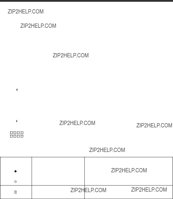
Operator Status Row Indicators
The operator status row is the area below the last data row and is separated from the rest of the screen by one nonintensified line. The operator status row contains symbols that indicate current operating conditions. These symbols are either System indicators or Local indicators.
Note: The symbols shown below are generated when the display station is attached to a MTX/MTC 1174 Network Controller, a Memorex Telex 1274 Control Unit, a Memorex Telex 1374 Control Unit, an IBM 3274 Control Unit, or an IBM 3174 Control Unit.
Column Numbers
Figure
System Symbols
The following types of operator status row symbols are generated by the system:
???Readiness and System Connection
??????Do Not Enter??? (Input Inhibited)
???Reminder
???Shift and Mode
???Printer Status*
???Entry Assist
???Response Time Indicators
*Printer Status symbols are system symbols if the printer is a host addressable printer. They are local symbols if the printer is a local printer.

Setup Menus, Controls, and Indicators
Readiness and System Connection Symbols
These symbols are displayed either alone or in combinations to indicate the readiness status of the display station, control unit, and system.
???Do Not Enter??? (Input Inhibited) Symbols
The X (Do Not Enter) symbol indicates that the display station does not accept input from the keyboard. Additional symbols are displayed to the right of the X to define why the input is not accepted.
The host system has locked the keyboard. Look for a message or
press the Reset key. On SDLC models, the host program uses the X SYSTEM System Lock System Lock symbol to request the operator to send the next
message.
Setup Menus, Controls, and Indicators

Setup Menus, Controls, and Indicators
Reminder Symbols
These messages are a reminder that a condition has occurred.
Shift and Mode Symbols
These messages indicate the shift and mode the keyboard is using.

Setup Menus, Controls, and Indicators
Printer Status Symbols
These messages are displayed during print operations to indicate where the operation is performed and the progress of the print job.
Entry Assist Indicators

Setup Menus, Controls, and Indicators
Response Time Monitor Indicators
.
The display station is not allowed to display the response


 . Display Unauthorizedtime by the host system, although the control unit enabled the Response Time Monitor.
Local Symbols
The following types of operator status row symbols are generated by a locally attached device:
???Local Error
???Record/Play
???Device Dependent
Local Error Indicators
Setup Menus, Controls, and Indicators
Record/Play Symbols
These messages are displayed on the operator status row when the display station is in Record/Play mode.
Device Dependent Symbols
A key has not been pressed or the display has not received Auto Dimany data for the specified minutes. Press any key to return the
display contents.

Chapter 4. Operating Procedures
Before you begin to operate the 1483, ensure that the display station is attached to a powered, operational control unit or processor. Refer to Page
Preparing to Operate
After the display station has been properly installed and connected to its control unit, it is ready to operate online. To ensure that the display station is prepared for operating, perform the following procedure. If you encounter operational difficulty or if the display station malfunctions, refer to Chapter 7.
1)Turn the security lock key counterclockwise to unlock the keyboard.
2)Set the
3)An alarm sounds briefly. The cursor is displayed in the upper left corner of the screen and the operator status row displays one of the following Ready symbols:
???6 ??? If attached to a Telex 276 Control Unit/Display Terminal, or IBM 3276
Control Unit Display Station.
???4 ??? If attached to a Memorex Telex 1274, a Memorex Telex 1374, a Memorex
2274, or an IBM 3274 Control Unit.
???I or i ??? If attached to an IBM 4300 processor.
???S ??? If attached to a MTX/MTC 1174 Network Controller or IBM 3174 Control Unit.
The
Note: Refer to ???Operator Status Row Indicators??? on Page
4)If the
If B is displayed in the first character position of the operator status row, refer to Chapter 7.
5)Adjust the Brightness control, the Contrast control, the Vertical Centering control, and the Horizontal Centering control, if necessary.

Operating Procedures
Adjusting the Screen Display
The 1483 is designed to operate with a color SVGA or VGA, or a monochrome SVGA or VGA monitor. If the screen is not displaying correctly, or there is interference from nearby electronic devices, you may need to change the vertical refresh rate (color) or mode/intensity setting (monochrome) on your monitor. Follow the appropriate procedure below.
Color Monitor
If you use a color monitor, two vertical refresh rates are possible, 72 Hz mode (the default) and 60 Hz mode.
To change the vertical refresh rate, turn the
F1 ??? Sets a color monitor to 60 Hz vertical refresh rate.
F2 ??? Sets a color monitor to 72 Hz vertical refresh rate.
F7 ??? For multifrequency monitors that can operate up to 42 KHz, sets vertical refresh rate to 75 Hz.
Monochrome Monitor
To adjust the mode or intensity setup, turn the
F3 ??? Sets the monitor to
F4 ??? Sets the monitor to
F5 ??? Sets the monitor to
F6 ??? Sets the monitor to
Operating Procedures
Assigning a Coax Printer
Each display station in a system configuration can be assigned a Host printer for generating copies of information displayed on the screen. These copies can be used to maintain records of terminal/CPU transactions.
For 
 ??? ??? ) on the operator status row. For
instead of Screen printer or Trimmed Print. This allows you to assign the coax printer.
Consult your supervisor for an available coax printer???s ID number and enter the two- digit number for the printer being assigned. The
If an invalid ID number is entered for a Host printer, the ???What???? symbol ( X ?+) appears on the operator status row. If this occurs, press the Reset key and try another number.
Data Entry Function
The data entry function consists of writing data messages in an acceptable form for computer processing. As you enter messages through the keyboard, they are displayed on the screen either as unformatted information or according to a program determined format. Attributes of the formatted display screen fields control the amount and type (alphanumeric or numeric) of entered data.
Figure 

 ) to be displayed on the operator status row. The unprotected (or entry) fields accept new or revised information from the operator. Some application programs further designate an entry field by displaying the cursor in the unprotected field???s first character position.

Operating Procedures
Alphanumeric Field
Numeric Field
Attribute Character
(not displayed)
Figure
Unprotected fields are classified as either alphanumeric or numeric. Alphanumeric fields can accommodate both alphabetic and numeric data characters. Numeric fields are controlled by the application program so that attempts to enter characters other than digits 0 through 9, a period, a Dup key, or a minus sign result in an error. On international keyboards, the comma can be entered instead of the period. The display station with a Data Entry keyboard automatically shifts into Numeric mode whenever the cursor enters a numeric field.
Data characters in unprotected fields also can be displayed as intensified (brighter) fields. In applications requiring the use of confidential information, both the protected and unprotected fields can be programmed to be nondisplayed fields.
Note: Use of nondisplayed fields precludes visual verification of entered data before transmission to the CPU.
Before you can begin to enter data characters, the display station must access the CPU and its application program. Access is usually achieved by using the Attention, Program Access (PA), Function (F), Clear, or Enter key, or through a series of
Keyboard Operations
The description of keystroke functions and operations initiated from the keyboard in this section applies to display stations with

Operating Procedures
Moving the Cursor
The cursor always indicates the next available character position on the screen. For applications using an unformatted display screen, select the location for the next character to be entered by moving the cursor to the selected screen position. The following keys are used for positioning the cursor:
Press the Up Arrow key ( ) to move the cursor up on the screen.
Press the Down Arrow key ( ) to move the cursor down on the screen.
Press the Left Arrow key ( ) to move the cursor horizontally left one position for each depression.
Press and hold the Alt and Left Arrow keys ( ) to move the cursor left two positions at a time. When the cursor moves beyond the edge of the screen, it ???wraps??? or reappears at the last character position of the previous line.
Press the Right Arrow key (  ) to move the cursor horizontally right one position for each depression.
Press and hold the Alt and Right Arrow keys (  ) to move the cursor right two positions at a time. When the cursor moves beyond the edge of the screen, it ???wraps??? or reappears at the first character position of the next line.
Press the New Line key (
 ) to move the cursor to the first entry position on the next line. When the cursor is at the last entry position on the bottom line of the screen, pressing the New Line key moves the cursor to the first entry position at the top of the screen.
Press the Backspace key ( ) to move the cursor backward.
Press the Home key to move the cursor to the first available character position on the screen (Home on  on
on
If the application uses a formatted display screen, the following three additional keys can be used to position the cursor:
Press the Tab key ( 
 ) to move the cursor forward to the first entry position of the next entry field.
Press the Backtab key ( ) to move the cursor back to the first entry position in the current or preceding entry field.
Press the Skip key (Data Entry keyboards only) to move the cursor to the first entry position in a subsequent entry field.
For applications using unformatted display screens, pressing the Tab, Backtab, or Skip key returns the cursor to the first available character position on the screen.
Operating Procedures
Entering Data Characters and Selecting Modes
Alphabetic, numeric, and special characters can be entered by pressing their corresponding keys.
After filling the last data line of the display screen, the cursor automatically returns to the first available character position, and entry of additional data may write over any previously entered characters. To prevent loss of previous entries, transmit the data message to the CPU whenever the screen has been completely filled with data. Refer to ???Message Transmitting Function??? on Page
Uppercase characters or the upper characters on dual character keys are entered by selecting the Shift or Numeric mode before pressing the key. On Data Entry keyboards, you can enter alphabetic characters in numeric fields by using the Shift (  ) and Alpha (
  ) keys (see ???Numeric Lock Mode,??? below).
Shift Mode
Hold the Shift key (  ) down while entering data to select upper characters on dual character keys or uppercase characters for alphabetic keys, or press and release to turn off the Shift Lock feature for keyboards with typewriter layouts.
Shift mode is designated on the operator status row by the  symbol.
Press the Shift Lock key (  ) to lock the keyboard into Shift mode. For Typewriter keyboards, press either Shift key to unlock. For Data Entry keyboards, press the Shift Lock key again to exit Shift mode. For
Numeric Lock Mode
Numeric Lock mode is set or reset on the Offline Keyboard menu (Figure
On Typewriter keyboards, the display station goes into lowercase mode when the cursor enters a numeric field. On Data Entry keyboards, the display station goes into uppercase mode when the cursor enters a numeric field.
Nonnumeric characters can be entered in numeric fields by the following methods:
For Data Entry keyboards and Typewriter keyboards, press the Shift key (  ) to enter uppercase characters in a numeric field.
For Data Entry keyboards only, press the Alpha key (  ) to enter any lowercase character in a numeric field.

Operating Procedures
The Shift Lock key does not override the Numeric Lock feature.
Keystroke Record/Playback
The Keystroke Record/Playback function enables you to reduce the number of keystrokes required for a frequently repeated entry such as a logon sequence or an address. Keystroke sequences can be stored for each of the Function keys. The combined total of stored keystrokes cannot exceed 7000 and the Shift key and Alt key each count as two keystrokes. The entered keystroke sequences are stored in nonvolatile memory, which means that the data is retained even if the power is turned off.
Calculator keystrokes can be recorded with the Record/Playback feature. Entering Calculator mode, importing data, doing calculations, exporting data, and exiting Calculator mode can all be recorded. The only limitation is that the status of the calculator (on or off) to begin playback must be the same as when the record sequence was started.
Storing Keystroke Sequences
Keystroke sequences are stored by keying as follows:
1)Press the Record key. R, a number indicating the available keystroke storage space, and the Record key indicator are displayed on the operator status row.
2)Press an F or PF key. The selected key number is displayed on the operator status row along with the number of keystrokes that have already been assigned to that key, if any. The key number is displayed in high intensity. At this point, you can press the Record key or the Quit key to exit to Online mode.
3)If keystrokes are already assigned to this key, you can clear them by pressing the Delete key (  ). The keystrokes are deleted and you exit to Online mode. If you do not want to delete the previously assigned sequence, press Record and choose another Function key. While you are entering keystrokes, press the Quit key to clear the currently recorded keystrokes and exit to Normal mode.
4)Begin typing the keystroke sequence. If the selected Function key has no keystrokes previously assigned to it, the number on the status row decreases by one each time you press a key. The number decreases by two every time you press a Shift or Alt key.
To record

Operating Procedures
5)If you want to stop recording keystrokes momentarily to perform other operations,
press the Alt key followed by the Pause key. The symbol R  ^ is displayed on the operator status row. Press the Pause key again to continue recording keystrokes.
6)Press the Record key to store the sequence and exit Record mode.
Playing Keystroke Sequences
A stored sequence is automatically keyed in Playback mode by doing the following:
1)Set the cursor to the selected insertion location.
2)Press the Play key. P is displayed on the operator status row along with the total number of recorded keys.
3)Press the Function key under which the sequence is stored. The stored characters are keyed back at approximately five characters per second. Press the Quit key during replay to return the display terminal to Normal mode. The P is no longer displayed on the operator status row after playback completes.
4)After you press the Pause key in Record mode, the replaying temporarily stops and
the symbol P ^ is displayed on the operator status row.You can temporarily resume normal operations and press the Play key to continue replaying the rest of the recorded keystrokes.
Record/Play Security Mode
When you enable this option, you cannot use the alphanumeric keys on the keyboard to record data, If you try, the 1483 automatically exits from Record/Playback mode. It also prevents you from playing back data recorded in the Command or Function keys. If you press a Function key, the display station exits from Record/Playback mode.
Enabling Record Security Mode
Enable Record Security mode by selecting Play/Record Option on the System Manager menu (Figure
Disabling Record Security Mode
To disable Record Security mode or change from a more restrictive security level to a less restrictive level, you must get a service technician to reset the selection.

Operating Procedures
Cursor Select Data Entry
The Cursor Select key, CrSel, can be used to select certain data fields from a formatted screen. The application program must define selectable fields by writing the appropriate attribute. These data fields are read by the application program for additional processing.
Each selectable data field is preceded by an appropriate field attribute character and a designator character. Designator characters precede one of two types of fields: selection fields or attention fields. With the Cursor Select key, items in a selection field can be selected and then the program can be notified of the selection by selecting an attention field.
An unselected selection field is preceded by a question mark (?), which changes to a greater than symbol ( >) when the field is selected. Attention fields are preceded by an ampersand (&) or space. These symbols do not change when an attention field is selected.
To select or deselect a field, move the cursor to cover the appropriate designator character or any character in the field and press the Cursor Select key. The question mark preceding the field changes to a greater than symbol after the field has been selected. If you accidently select the wrong field, you can deselect it by pressing the Cursor Select key again in the same field. The greater than symbol preceding the field changes to a question mark after the field has been deselected.
For some programs, after you have finished selecting fields, press the Enter key to send the fields to the host application program for additional processing. The selected fields also can be sent by selecting an attention field designator character using the Cursor Select key. The ampersand and space characters designate attention fields. Move the cursor to cover any character in the field and press the Cursor Select key to send the attention field data along with data in any other selected field on the screen.
Exiting the Cursor Select operation depends upon the program in use. Refer to a user???s guide for your application for the proper procedure.
Data Editing Function
You can change the contents of a message before you send it to the CPU, or you can call up a previously entered message for editing.
Use the Attention, PA, F, PF, Clear, or Enter key to call up a previously entered message, or use a series of
All keys described in ???Keyboard Operations??? beginning on Page
Press the Insert key to enter Insert mode for adding characters at the cursor???s current position. Press Reset to exit Insert mode. The symbol  is displayed on the operator status row to indicate the display station is in Insert mode.

Operating Procedures
Press the Delete key (  ) (Delete on
Press the Alt key and the Delete Word key (  ) (DelWd on
Press the Erase to End of Field key, Erase EOF (ErEOF for
Press the Alt and Er Inp keys to erase all entry field positions and to move the cursor to the first available character position.
Press the Shift key (  ) and Dup key (Dup key only on
Press the Shift key (  ) and Field Mark key (Field Mark key only on
Message Transmitting Function
After you have filled all character positions on the screen, send the displayed information to the CPU before you continue to enter data. When a data character is entered in the
After filling all required character positions on the screen, press the Enter key to request a communications line for sending displayed data to the CPU.
Press the Clear key to erase all displayed data on the screen, return the cursor to the first available character position, and signal the CPU that a ???clear??? operation has occurred.
The application program in use determines specific functions of the Program Access (PA) and Function (F or PF) keys. Contact your supervisor or refer to a system user???s guide for further information regarding these keys.
The display station also can be used to send system request messages to the CPU, depending on the online rules condition symbol that is displayed on the operator status row.
If online rules A apply (A is displayed on the operator status row), press the Alt and Sys Rq (System Request) keys to send the CPU a message that the display station may be malfunctioning or that a test request message is on the screen. If online rules B apply (B is displayed on the operator status row), press the Alt and Sys Rq keys to clear the display and switch the display station between the control (or master) program and application programs. Contact your supervisor or refer to a system user???s guide for additional information about this key combination.

Operating Procedures
Print Function
The display station can send a print request to the host system or it can print data locally if a local screen printer is attached. A desktop/screen printer must be ordered separately. To initiate host printing or local screen printing, press the Print key. The following menu is displayed on the status line:
Figure
This menu enables you to specify the print type and to send paper control and session control commands. Press the Enter key when you are ready to start printing.
Setting Print Type
Press F13 to toggle through the Print type options. Select one of the following:
COAX (default) ??? The display contents are printed on the printer attached to the control unit.
SCREEN ??? The display contents are printed on the local printer attached to the display station. For local screen printing, you can specify other print parameters, such as Print Quality, Lines Per Inch, Lines Per Page, and Characters Per Inch. (See the Online Printer menu, Figure
TRIMMED ??? A portion of the display contents is printed on the local printer attached to the display station (Partial Screen Print). Specify the portion of the screen to be printed by following the steps below.
As you toggle, the options are displayed on the status line next to PRINT; for example,
PRINT COAX, PRINT SCRN, PRINT TRIM.
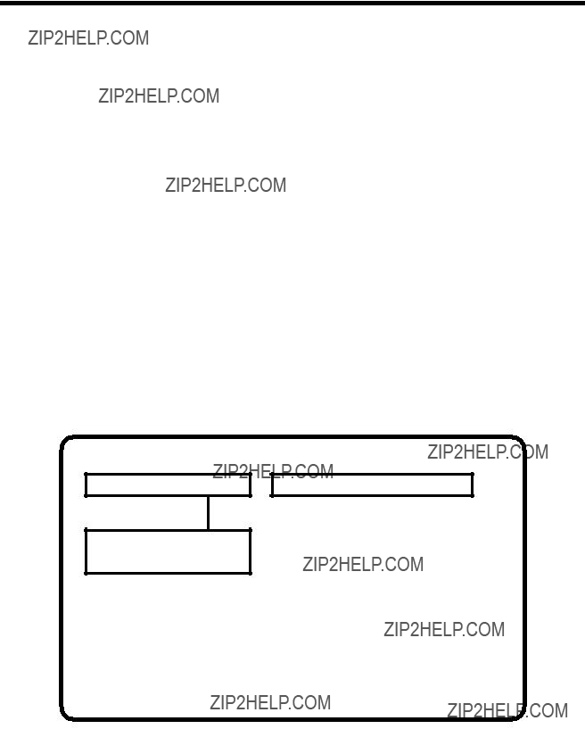
Operating Procedures
If you select the PRINT TRIM option, the screen is displayed with a box around the printable area or the last print area defined with this option. To change the size of the trim area, follow these steps:
1)Press the CrSel key to move the cursor to the upper left (or lower right) corner of the area you want to define.
2)Press the arrow keys to move the cursor and the box corner where you want them. The box corner moves with the cursor.
Note: The new upper left and lower right corner row/column settings are displayed in the Trimmed Print Corners field of the Online Printer menu as described on Page
You can select a location on the printed page for the trim area output by specifying a Print Position option on the Online Printer menu (Figure
Press F14 if you want to set paper control or session control options. The menu shown in Figure
Use the arrow keys to select Paper Control or Session Control.
Paper Control
The paper control options let you send a line feed or form feed command to the printer.
To send a command, highlight Line Feed or Form Feed and press the Enter key.
Printer/Session Screen Menu Screen
Line Feed
Form Feed
Use Arrow Keys to select
Use ENTER Key to execute
RESET Key Exits
Figure

Operating Procedures
Session Control
Select Session Control by using the arrow keys to highlight Session Control on the Paper Control Options menu. The Session Control Options menu is displayed (Figure
The session control options let you cancel the host print job (LU1 only) or, if you are executing an LU1 print, let you send a PA1 or PA2 command to the SNA host.
Note: To cancel a local print, press the Device Cancel key or the Quit key.
To select a Session Control option, move the highlight to the option you want to execute and press the Enter key.
Press the Reset key to exit from the Printer Control Options menu or the Session Control Options menu. You return to the Online Print menu (Figure
Printer/Session Screen Menu Screen
Cancel Print
PA1
PA2
Use Arrow Keys to select
Use ENTER Key to execute
RESET Key Exits
Figure
Printing
Press the Enter key to send the print request.
Exiting from the Online Print Menu
Press F3 or PF3 to exit from the Online Print menu and return to normal online operations.

Operating Procedures
Partitioning
The Partitioning function is a controlled function. To use the Partitioning function, your display station must be attached to a controller that supports partitioning. The display receives partitioning commands from the host only while in Native mode.
To scroll vertically through data in the viewport during partitioning, the Back and Fwd (Forward) keys are used in the following manner:
To scroll forward vertically (down through the data in the presentation space), press and hold the Alt and Fwd keys. This moves the data up the viewport.
To scroll backward vertically (up to the beginning of the data in the presentation space), press and hold the Alt and Back keys. This action pushes the data down the viewport.
Extended Select Function
To perform the Entry Assist and Response Time Monitor functions, press the Extended Select (ExSel) key while the display station is in Native mode. The display station must be attached to a properly configured Memorex Telex 1274 Control Unit at firmware release 11.0 or higher, a MTX/MTC 1174 Network Controller, or any other properly configured controller that supports Extended Select.
Extended Select Keyboard Overlays
Figure
Note: On the

Operating Procedures
Figure
Entry Assist
The Entry Assist function facilitates the creation and editing of text such as memos, letters, and documents. For more information on the Entry Assist function, see Chapter 5, ???Entry Assist.???
In order to use the Entry Assist function, the control unit to which the display station attaches must provide Entry Assist support. Consult the control unit operator???s manual for additional Entry Assist specifications and operating procedures.
Response Time Monitor
The Response Time Monitor (RTM) records the speed of communication between the devices attached to a valid, properly configured control unit (Memorex Telex 1274 or IBM 3274) and the host CPU with which they are attached. The RTM is accessed and exited by pressing the ExSel key, followed by the F19 key
Keyboard Switch Settings
The keyboard switches are set at the factory according to the keyboard ordered. You should not need to change them. If the settings are inadvertently changed, set them according to the table on Page
Some keyboards do not have access to the keyboard switches. If you have this kind of keyboard, you can set the switches through key sequences. See ???Setting the Keyboard Switches through Key Sequences??? on Page
Operating Procedures
Setting the Keyboard Switches through Key Sequences
To set the keyboard switches through key sequences, follow these steps:
1)Press the left Alt, Reset, and Caps Lock keys at the same time. You enter ID Set mode with all switches set to Off (indicated by I in the table above).
2)Function keys 1 through 12 correspond to positions 1 through 12. Referring to the table above, for each position that you want to set On, press the corresponding function key.
For example, to set Switch 6 On, press F6.
4)When the ID is set, press the left Alt, Reset, and Caps Lock keys at the same time to leave ID Set mode and save the switch settings.
If you press the wrong function key while in ID Set mode, you must leave ID Set mode, enter ID Set mode again (this resets all the switches to Off), and press the correct function key.

Operating Procedures
Display Indicators
When lit, the Logic element
Cursor
After the display station has been powered on and has completed its
Using the Light Pen to Select Data
You can use the optional light pen to select data from fields that are defined for light pen operations. Ask your supervisor to tell you which fields on the screens you use are set up for light pen selection.
Do the following to select an item with the light pen:
???Press the light pen to the screen on the field you want to select.
???If you???ve turned on the Light Pen clicker, a click sounds when the field is selected.
???If the field is preceded by ?, the ? changes to > when the field is selected.
???If the field is preceded by &, processing begins as soon as you select the item.
If necessary, complete the selection by pressing a keyboard key (for example, Enter) or perform an additional light pen selection (like pointing to an End command).

Operating Procedures
Using the Electronic Security Lock
To invoke the secure (locked) mode, the operator enters the Lock sequence (Right Alt key, Right Shift key, and Enter key). The control unit displays  on the status line and the display adds a 3 to act as a prompt for a
  symbol.
Powering off the display while locked means it will be locked when powered on next time. Upon  3 is displayed, requiring all three password keys to be entered to unlock the display. To change the password, see ???Changing the Keyless Password??? on Page
If the Dim Timer is not ???off,??? and the keyless password is not ???off??? when the Dim Timer expires, the display station locks. Pressing the space bar once and entering the password ???unlocks??? the display.

Chapter 5. Entry Assist
The Entry Assist function enhances data entry, formatting, and editing on the 1483. Access to the Entry Assist function with the
Note: Entry Assist is a controller feature, available only if the 1483 is attached to a controller that supports Entry Assist capability.
*The Entry Assist keys shown in the table are not valid if the

Entry Assist
In addition to the format controls (discussed below) supported in Change Format mode, the following functions are supported in Document mode:
???Screen margins
???Tabbing
???Audible alarm indicating the approach of the end of the line
???Word wrap automatically moving an unfinished word to the next line when the word would extend beyond the right margin
???Autorepeat word forward and word reverse cursor movement
???Autorepeat character deletion
???Autorepeat
???Word deletion
Once formats are established, further data entry takes place in Document mode with the entry and editing functions listed above. Once text is entered, it remains in the given format even if the format is changed later or the terminal is taken out of Document mode.
Entry Assist Functions
Entry Assist functions consisting of formatting controls, cursor movement, and editing functions are described here for display stations with
Entering Document Mode
To enter Document mode, press the Document mode key (F1), then press the Change Format key (F3). A format scale is displayed at the bottom of the screen, enabling various format parameters to be altered. Cursor movement and editing controls are given to certain keys upon entry into Document mode. When in Document mode, the display shows the DOC message on the status row. The DOC message disappears when the display is taken out of Document mode.
Format Controls
Once the display is in Document mode, press the Chg Fmt key to display the format scale. This scale is displayed at the bottom of the display screen. A reverse video block cursor is displayed on the format scale in the same column position as the chosen cursor in the display area (the display cursor???s vertical position has no effect on the format scale cursor???s position). Refer to Figure

Entry Assist
Figure
To hide the format scale, press the Chg Fmt key again.
Use the Cursor Left ( ) and Cursor Right ( ) keys to move the format scale cursor to the desired position. Once the format scale cursor is in position, press the appropriate format function key. When a function key is pressed, the format scale cursor disappears and leaves in its place the appropriate format symbol. To make the cursor reappear, press the Cursor Left or Cursor Right key.
All of the format parameters are saved whenever the display exits Document mode. The last values established for the format parameters before exiting Document mode are in effect when the display returns to Document mode. The following format parameters (shown with their corresponding format symbols) can be changed on the format scale:
???Left margin ( < )
???Right margin ( >)
???Tab stops ( _ )
???
???Alternate right margin type ( | )
???Format scale origin (changes the scale origin from 1 to 0 and vice versa)
Left and Right Margins
To set or move the left or right margin, move the format scale cursor to the desired position, then press the less than symbol key ( < ) for the left margin or the greater than symbol key ( >) for the right margin. The symbol is displayed on the format scale in the selected position. Only one left margin and one right margin can be defined on the format scale at a time.

Entry Assist
When a margin is redefined, the margin symbol is replaced by a symbol for the new margin. Tab stops and the
When data is entered between the margins, the cursor can be located over the left margin column, and data can be entered in this column. However, the cursor will wrap before it reaches the right margin column. Data cannot be entered in this column during normal typing.
Even though a margin is defined and the display is in Document mode, data still can be entered to the left of the left margin or the right of the right margin. The left and right margins are established to stop the cursor during normal data entry. The Cursor Left and Cursor Right keys allow you to move the cursor beyond the margins, where data can be entered and modified the same as between the margins.
Alternate Right Margin Type
The standard right margin remains in effect during Document mode whether the Word Wrap function (described on Page
When the right margin is disabled (the alternate right margin set and Word Wrap is turned off), the right side of the screen acts as the right margin and text wraps at the screen???s margin regardless of word divisions. When Word Wrap is turned back on, the right margin previously in effect is reinstated.
To give an existing right margin the alternate right margin attribute, place the format scale cursor over the right margin symbol, then press the Cursr Sel key. The greater than symbol ( >) turns into a broken vertical bar ( ?? ) indicating that the right margin is released when the Word Wrap function is turned off. To restore the standard right margin, place the cursor over the broken vertical bar and press Cursr Sel again. The greater than symbol returns to the format scale.
Tab Stops
Setting tab stops on the format scale allows the tab keys to function as they do on a typewriter, treating the defined column positions as tab stops. Once they are set, tab stops are used in Document mode by pressing the Forward Tab ( 
 ) or Reverse Tab (
 ) key to move the cursor to the next tab stop to the right or left.

Entry Assist
Tab stops are set by placing the format scale cursor in the desired position, then pressing the Forward Tab key. The format scale displays an underscore ( _ ) in the new tab stop position unless a margin symbol or
Up to 20 tab stops can be defined in any position on the format scale. Attempts to enter more than 20 tab stops are ignored.
To clear a tab stop, place the format scale cursor on the tab stop symbol in question, then press the Delete Character key (  ). To clear all tab stops from the format scale at once, press the Clear key. All tab stop symbols are removed from the format scale.
For the
To set the
To disable the  ). The asterisk disappears and the function is disabled. If a tab stop is located at the
The Format Scale Origin
The format scale numbers can be shifted so that the scale begins with Position 1 instead of Position 0. Tab stops, margins, and
To change the scale origin, place the format scale cursor at the leftmost position on the scale, then press the CrSel key. The numbers on the line are shifted one space to the left. Pressing CrSel again returns the origin to 0.
Cursor Movement and Editing Functions
Cursor movement and editing functions are active whenever the display is in Document mode. These functions are subject to the limitations imposed by the format parameters currently set on the format scale.
Cursor movement and editing functions available in Document mode are the following:
???Word wrap.
???Autorepeat cursor movement to next word.
???Autorepeat cursor movement to previous word.

Entry Assist
???Delete word to the right.
???Autorepeat deletion of character to the right.
???Tab function inserting space characters.
???Backtab function.
???Backspacing with deletion.
???New line function observing left margin.
Word Wrap
The Word Wrap function is turned on and off in Document mode by pressing the F2 (Word Wrap) key. This parameter, like other format parameters, is saved when the display is removed from Document mode and returns to its last state when the display returns to Document mode. The Word Wrap symbol (  ) indicates that word wrapping is in effect. When the function is on, text entry is subject to word wrapping between the left and right margins.
Word wrapping occurs when a word being entered would extend beyond the right margin. When the character is entered that would go beyond the right margin, the entire word is moved down one line and to the left margin. If a space is entered in the position one character left of the right margin, the cursor is moved to the left margin of the next line without word wrapping. If the cursor is one space left of the right margin and the Dup key is pressed, the Dup character appears on the right margin and the Dup function works as defined outside of Document mode.
The positions previously occupied by the first part of the word are replaced by space characters. When a word is wrapped to the left margin of the next line, any null characters to the left of the left margin are changed to space characters to preserve the format when it is sent to the host CPU.
Word wrapping does not occur unless the entire row onto which the word is wrapped contains only nulls or spaces. In some cases word wrapping cannot occur. In these cases, input is inhibited and the status row shows the Too Much symbol ( X  ). Press the Reset key for additional entry. The following conditions prevent word wrapping:
???The word takes up the entire length of the line.
???There is already text on the next line.
???The current line is the last line on the screen.
???The next line begins with a protected field.

Entry Assist
If the display is in Insert mode and a word is inserted on a line, any word pushed beyond the right margin may be wrapped to the next line if the next line contains enough spaces after its last word or its margins contain enough nulls to make room for the wrapped word. If the word cannot be wrapped onto the next line, input is inhibited and the Too Much symbol is displayed on the status row.
Move Cursor to Next Word (Autorepeat)
To move the cursor to the next word, press and hold the Alt key, then press the Cursor Right key (  ). The cursor moves to the first character in the next word, or, if currently in a word at the end of a line, to the first space or null character following the current word. The cursor does not move into protected fields with this function.
The cursor is moved to the next word regardless of the location of the margins. If text is located outside the margins, the cursor moves to the text without recognizing the margins. The cursor wraps to the next row only when there are no more words in the current row. When the last word is reached on the last row, the cursor is wrapped to the first word on the first row of the display.
Continuing to hold down the Alt and Cursor Right keys causes the function to repeat automatically.
Move Cursor to Previous Word (Autorepeat)
Press and hold the Alt key, then press the Cursor Left key ( ) to move the cursor to the beginning of the current word (or, if already at the beginning of a word, to the beginning of the word to the left). If the cursor is located at the first word on a row, it is wrapped to the beginning of the last word on the previous row. If at the top left position on the screen, the cursor is wrapped to the beginning of the last word on the screen.
Continuing to hold down the Alt and Cursor Left keys causes the function to repeat automatically.
Delete Next Word
The Delete Word key (  ) is the alternate function of the Delete Character key (
  ) when the display is in Document mode. Pressing the Delete Word key erases the character at the cursor location and the remainder of the word to the right of the cursor. If the cursor is on the first character of a word, the whole word is erased. If the cursor is on a space or null, only the space or null is erased. Punctuation and spaces following a word are also erased (unless only part of the word is erased, in which case the space or null remains).
When a word is deleted, the cursor remains in place and subsequent data on the line moves to the left. Shifting does not occur for attributes, characters to the right of attributes, or subsequent lines of data. If deletion is attempted on an attribute or a protected field, input is inhibited and the Go Elsewhere symbol ( X 

 ) is displayed on the status row. Press the Reset key to enable additional entry.
Entry Assist
Cursor Tabbing
Pressing the Forward Tab key ( 
 ) causes the cursor to move to the next unprotected tab stop. Intervening unprotected null characters are converted to space characters to preserve the format when data is transmitted to the host CPU. If the cursor reaches an unprotected attribute before it reaches a tab stop, it will stop at the attribute. If no tab stops and no attributes are defined, the cursor moves to the top left position on the screen.
If there are tabs or unprotected attributes on the screen, tabbing does not allow the cursor to wrap from the lower right corner of the screen to the upper left corner of the screen.
For some programs, the introduction of additional data (in the form of nulls being converted into space characters) may cause problems. Programs should be verified for use with the tab function in Entry Assist.
Backtab Function
The Cursor Backtab function works like the Forward Tab function except that the cursor is moved to the previous tab stop or the first unprotected character of the current or previous field. Pressing the Backtab key ( ) causes a backtab operation. Nulls are not changed to spaces when a backtab operation is performed. The cursor will not wrap from the upper left corner of the screen to the lower right corner.
Backspacing with Deletion
Pressing the Backspace key ( ) in Insert mode deletes the character to the left of the cursor and causes the cursor to move left one character space. Characters to the right of the cursor on the same line are moved one character to the left. Attributes and characters to the right of attributes are not moved.
If the cursor is located at the left margin when the Backspace key is pressed, input is inhibited and the Go Elsewhere symbol ( X 

 ) is displayed on the status row. Press the Reset key to resume entry.
New Line Function
Pressing the New Line key (  ) causes the cursor to move down one line and return to the established left margin. If the left margin is protected, the cursor moves to the first unprotected position to the right of the left margin. Unprotected null characters to the left of the left margin are converted to spaces as long as there are no fields between the nulls and the cursor.
If the cursor is on the last row of the screen and the New Line key is pressed, the cursor is positioned on the first row of the screen.
If there are no unprotected locations between the margins, the cursor moves to the left margin of the first row on the screen.

Chapter 6. Calculator Operation
The 1483 has a
Calculator keystrokes can be recorded with the Record/Playback feature. See Page
The Decimal calculator can be selected in Calculator mode by pressing F10.
The Binary calculator can be selected in Calculator mode by pressing F2.
The Hex calculator can be selected in Calculator mode by pressing F16.
Once a specific calculator is selected, it is the calculator displayed whenever Calculator mode is entered until changed by selection of another calculator.
Calculator Mode
To enter or exit Calculator mode, depending on the attached keyboard, press and hold the Alt and F12 keys
A calculator simulation is displayed on the screen as in Figures
Moving the Calculator on the Screen
The following keys reposition the Decimal, Binary, and Hex calculators on the screen:
The Cursor Direction keys can be used to reposition decimal or binary calculators.

Calculator Operation
Jumping Between Calculator Mode and Normal Operation
If you want to return keyboard functionality to the coax screen without losing the calculator display, press the F12/F24 key. Make the changes to the coax screen, then press the Alt and F12/F24 keys to return to Calculator mode.
Even though the
Decimal Calculator
Use the decimal and numeric keys on the numeric keypad or the main keypad to enter numbers for calculation.
After entering a number, enter the mathematical symbol designating the operation to be performed. On the
+ for addition
- for subtraction
* for multiplication
?? or / for division
If you want to enter a negative number, enter the number and then press the +/- key indicated on the calculator simulation.
Press the = key on the calculator simulation (or on the main keypad) to display the result of your computation in the calculator???s Results field.
Setting the Decimal Place
You can set from 0 through 9 decimal places on the calculator or you can choose to not specify the number of decimal places.
If you select 0 through 9 decimal places, only the number of decimal places you select is displayed in the Results field of the calculator. You can enter numbers for calculation with more decimal places than can be displayed in the Results field. If the result of the calculation has more decimal places than can be displayed in the Results field, the system rounds off the answer before it is displayed.
You can also choose to not specify the number of decimal places. If you do not specify the number of decimal places, the calculator displays as many decimal places as necessary for the answer.
Note: The calculator can display a maximum of 13 digits in the Results field. If a calculation causes a result larger than the Results field maximum of 13 digits, the overflow symbol ? is displayed. Press C/E (Clear Entry [Clear on the
Calculator Operation
To set the decimal place, with the 1483 in Decimal Calculator mode, press the PF3 key, then:
To set from 0 through 9 decimal places ??? press the 0 through 9 key ( D0 through D9 is displayed at the top of the Results field)
Or
To not specify the number of decimal places ??? press the N key.
D5
Figure
Calculating Percentages
To calculate a percentage of a number with the Decimal calculator:
1)Enter the number.
2)Press the % key indicated on the calculator simulation of the numeric keypad or the % key on the main keypad.
3)Enter the percentage.
4)Press the = key indicated on the calculator simulation or the = key on the main keypad.

Calculator Operation
The calculated percentage is displayed in the Results field of the calculator simulation.
Other Calculator Functions
Press the C/E key once to clear the current entry. Press the C/E key a second time to clear the current total. You can also use the Clear key on the main keyboard.
Press the M + X key to add the currently displayed value to memory. M is displayed at the bottom of the Results field to indicate that there is a number in memory.
Press the M  X key to recall and display the memory contents. The memory contents are recalled in the current Calculator mode equivalent value regardless of the mode in which the value was saved. For example, if 128 is saved with the Decimal calculator and recalled with the Binary calculator, 100000002 is displayed in the Results field.
Press the X  M key to store the currently displayed value in memory. Press this key with zero in the Results field to clear the memory.
Press the 
 X key to import the value from the current cursor position on the coax
screen to the Results field on the calculator. The import field holds a maximum of 13 digits.
Note: The calculator interprets a comma in the import field as a European decimal point. Any numbers to the right of the comma are treated as decimal point values and not whole numbers (for example, 10,500 is treated as if it were 10.5).
Press the X 
 key to export the value in the Results field to the current cursor position on the coax screen.
Press the PF1 key to toggle the calculator simulation between full simulation display and display of the Results field only.

Calculator Operation
Binary Calculator
Results Field 
1111111000000
1
+
0
Figure
Binary Mathematical Operations
Use the numeric keys on the numeric keypad or the main keypad (1 or 0) to enter numbers for calculation. After entering a number, enter the mathematical symbol designating the operation to be performed. For the
+ for addition
- for subtraction
* for multiplication
?? or / for division
X or XOR for logical XOR
! or | for logical OR
& for logical AND
If you want to enter a negative number, enter the number and then press the +/- key indicated on the calculator simulation. Press the = key on the calculator simulation (or on the main keypad) to display the result of your computation in the calculator???s Results field.
If a calculation causes a result larger than the Results field maximum of 13 digits, the overflow symbol ? is displayed. Press C/E (Clear Entry [Clear on the

Calculator Operation
Other Calculator Functions
Press the C/E key once to clear the current entry. Press the C/E key again to clear the current total. You can also use the Clear key on the main keyboard.
Press the M + X key to add the currently displayed value to memory. M is displayed at the bottom of the Results field to indicate that there is a number in memory.
Press the M  X key to recall and display the memory contents. The memory contents are recalled in the current Calculator mode equivalent value regardless of the mode in which the value was saved. For example, if 128 is saved with the Decimal calculator and recalled with the Binary calculator, 100000002 is displayed in the Results field.
Press the X  M key to store the currently displayed value in memory. Press this key with zero in the Results field to clear the memory.
Press the  X key to import the value from the current cursor position on the coax screen to the Results field on the calculator. The import field holds a maximum of 13 digits.
Press the X 
 key to export the value in the Results field to the current cursor position on the coax screen.
Press the PF1 key to toggle the calculator simulation between full simulation display and display of the Results field only.
Hex Calculator
PF2 PF10 & | X < > U V
Figure

Calculator Operation
Hex Mathematical Operations
Use the numeric keys on the numeric keypad (0 through 9) and the keys A through F to enter numbers to be operated on. You can also use the main keypad to enter numbers (0 through 9) and the keys A through F.
After entering a number, enter the mathematical symbol designating the operation to be performed. For the
+ for addition
- for subtraction
* for multiplication ?? or / for division
X (main keyboard) for logical XOR ! or | (main keyboard) for logical OR & (main keyboard) for logical AND
If you want to enter a negative number, enter the number and then press the +/- key indicated on the calculator simulation.
Press the = key on the calculator simulation (or on the main keypad) to display the result of your computation in the calculator???s Results field.
If a calculation causes a result larger than the Results field maximum of 13 digits, the overflow symbol ? is displayed. Press C/E (Clear Entry [Clear on the
Other Calculator Functions
Press the C/E key once to clear the current entry. Press the C/E key again to clear the current total. You can also use the Clear key on the main keyboard.
Press the M + X key to add the currently displayed value to memory. M is displayed at the bottom of the Results field to indicate that there is a number in memory.
Press the M  X key to recall and display the memory contents. The memory contents are recalled in the current Calculator mode equivalent value regardless of the mode in which the value was saved. For example, if 128 is saved with the Decimal calculator and recalled with the Hex calculator, 8016 is displayed in the Results field.
Press the X  M key to store the currently displayed value in memory. Press this key with zero in the Results field to clear the memory.
Press the 
 X key to import the value from the current cursor position on the coax screen to the Results field on the calculator. The import field holds a maximum of 13 digits.
Press the X 
 key to export the value in the Results field to the current cursor position on the coax screen.
Press the PF1 key to toggle the calculator simulation between full simulation display and display of the Results field only.

Chapter 7. Problem Determination
and Maintenance
Diagnostic Testing Function
The 1483 Display Station can perform two types of diagnostic tests: offline tests that check the operation of the display station independent of its attached control unit, and online tests that check the 1483 as it interacts with the attached control unit. For purposes of customer problem determination, some offline tests are presented in this section. For information about online tests, refer to your controller???s user???s guide.
Offline Tests
The display station temporarily enters Offline Test mode each time it is powered on. The display station???s own series of Basic Assurance Tests (BATs) are run each time the display station is powered on. If an error is detected, the alarm sounds and an error condition may be displayed in row 1, column 1. K is displayed for a keyboard error and L is displayed for a logic error.
Hold down a key while simultaneously turning on the
Problem Determination and Maintenance
System Manager Menu
To utilize the System Manager menus, highlight System Manager Menus on the Offline Test menu and press the Enter key. If password protection is enabled (see Page
These screens are for System Managers and service technicians.
Figure
Basic Assurance Tests
The Basic Assurance Tests selection starts a series of tests running on the display station. The tests run in a continuous loop until you stop them by pressing the Reset key. To start the tests, highlight Basic Assurance Tests and press the Enter key. To stop the continuous tests, press the Reset key again.
Problem Determination and Maintenance
KBD Test
To test the keyboard, highlight KBD Test on the System Manager menu and press the Enter key. A sample keyboard layout is displayed.
Figure
Note: This is a sample keyboard test screen. The test screen displayed depends on the keyboard attached to the display station.
Each key on the keyboard can be tested by pressing the key. If the key is operating correctly, the corresponding key on the display should toggle from an open box to a filled box and back with each keystroke.
To exit this test and return to the System Manager menu, press and hold the Alt key while you press the Test key.

Problem Determination and Maintenance
Mod Size Test
To start this test, highlight Mod Size Test on the System Manager menu and press Enter. This test displays a test screen for each of the selectable screen sizes. The test screen changes from Mod 2, to Mod 3, to Mod 4, to Mod 5 each time you press the Enter key. To exit from this test and return to the System Manager menu, press Reset. An example of the Mod 2 Test screen is shown below.
.
.
.
.
.
.
.
.
1
.
.
.
.
.
.
.
.
2
.
.
.
.
Figure
Screen Centering
To center the display area on the screen, use the Up or Down Arrow key to highlight Screen Centering and press the Enter key. The Centering screen is displayed (Figure
Use the Up, Down, Left, and Right Arrow keys to move the Centering screen up, down, left, and right. When the Centering screen is centered on the display station screen, press the Reset key to return to the System Manager menu.
Note: The Up and Down Arrow keys do not move the Centering screen up and down if the display station is operating in 60 or 75 Hz mode.
To return to the
Adjusting the Contrast
If you are using a

Problem Determination and Maintenance
Press the F3 key to decrease the contrast level or press the F4 key to increase the contrast level.
H EEEEEEEEEEEEEEEEEEEEEEEEEEEEEEEEEEEEEEHHEEEEEEEEEEEEEEEEEEEEEEEEEEEEEEEEEEEEE H
H EEEEEEEEEEEEEEEEEEEEEEEEEEEEEEEEEEEEEEHHEEEEEEEEEEEEEEEEEEEEEEEEEEEEEEEEEEEEE H
Figure
Selecting Password Protection
Use the Password option to set password security options for access to setup menus. To set password options, highlight Password on the System Manager menu and press the Enter key. The following message is displayed to warn you that data may be lost:
Data May Be Destroyed
Hit ENTER to Continue or RESET to abort
Press the Reset key to abort the function without changing the security level, or press the Enter key to display one of the following security level choices: Disabled, System Manager Menu, or All Menus.
Press the Enter key to toggle through the security level choices. Each time you press the Enter key, the warning message is displayed. Press the Enter key again to display the next security level choice.
Press Reset to return to the System Manager menu with no changes made, or use the Down Arrow key to highlight Enter Password and follow the directions in ???Enter Password,??? on Page
Note: If you change keyboard styles (that is, the physical keyboard, not just the keyboard type), the system may not recognize the password when you enter it on the new keyboard.

Problem Determination and Maintenance
Before changing keyboard styles, clear out the current password by selecting Disabled, change keyboards, then enable password protection by selecting System Manager Menu or All Menus and enter a new password with the
Enter Password option, below.
Enter Password
To enter a password, use the Down Arrow key to highlight Enter Password and press the Enter key. Enter a password from one to eight characters, then press the Enter key again.
A message is displayed that tells you to enter the password again for verification. Enter the password again and press the Enter key. The password is now in effect for the menu or menus you selected in the Password option.
Note: If the password is lost or unknown, you must call a MTX service representative to clear out the unknown password so that you can set a new one.
Enter Serial #
Note: Check with the system operator before changing this value.
You can enter the display station???s serial number by highlighting Enter Serial # on the System Manager menu. Press Enter ??? the first character of the displayed serial number is highlighted and the numbers
1)Move the underline cursor using the Left and Right Arrow keys until the appropriate symbol is displayed in the first character image block in the serial number entry area.
2)Press the Enter key when the underline cursor is located under the character that you want to select. The entry block automatically moves to the next position in the serial number entry area and the underline cursor moves under the displayed character.
3)Repeat Steps 1 and 2 until all digits of the serial number are entered.You can correct the characters you enter when the last character is entered and the cursor wraps to the first character. To clear all entries, press the Clear key.
4)When you finish entering the serial number, press the Reset key. The System Manager menu is displayed.
5)Press the Reset key to return to the initial Offline Test menu.
The serial number, along with the Product ID, is stored in the display???s nonvolatile memory and is available to the control unit for systems statistics gathering by NetView. The control unit must be at the appropriate microcode level to support SNA host requests for Vital Product Data.

Problem Determination and Maintenance
Init NVRAM Counters
This menu selection enables you to reset the NVRAM counter to zero. The NVRAM counter records all resets to NVRAM by the system or by the operator.
To initialize the NVRAM counters, highlight Init NVRam counters on the System Manager menu and press the Enter key. The following message is displayed to indicate data may be lost:
Data May Be Destroyed
Hit ENTER to Continue or RESET to abort
Press the Reset key to abort the function without resetting the counters or press the Enter key to reset the counters to zero. Pressing either key returns you to the System Manager menu.
KBD Switches
Select this menu selection to display the current keyboard switch settings.
Part # (Program)
This item is for information only. The Part # item displays the current level of the main PROM revision in the display station. You cannot change this information.
Play/Record Option
Only the system manager should change this menu selection from the default setting of Full Functions. The system manager uses the Play/Record option to set security options for Play/Record functions that, once set, cannot be changed from this menu. To set security options, highlight Play/Record Option and press the Enter key. The message Change will be Permanent! Hit Reset to Abort is displayed.
Press the Reset key to return to the System Manager menu with no changes made or press the Enter key to change to the next selection ??? No Play/Rec in
Press the Enter key again to display the message Change will be Permanent! Hit Reset to Abort. Press the Reset key to return to the System Manager menu with No Play/Rec in
No Play Record.
Warning
Once a security level is active, you cannot change it to a less restrictive level from this menu. If you want to change to a less restrictive level, you must get a service technician to reset the selection to Full Functions or No Play/Rec in

Problem Determination and Maintenance
Reset NVRAM
When you reset NVRAM, you reset all setup options to their default settings.
To reset NVRAM, highlight Reset NVRAM on the System Manager menu and press the Enter key. The following message is displayed:
Data May be Destroyed
Hit ENTER to Continue RESET to Abort
Press the Enter key to reset NVRAM or press the Reset key to leave NVRAM as it is.
Default Settings for Setup Options

Problem Determination and Maintenance
Default Settings for Setup Options

Problem Determination and Maintenance
* Not displayed when NVRAM reset to default settings. ** Monitor dependent
Highlight Reset NVRAM on the System Manager menu and press Enter to reset the NVRAM and increment the NVRAM counter by one to record the reset function.
User Defined Data
The User Defined Data screen (Figure
To display the User Defined Data screen, highlight User Defined Data on the Offline Test menu (Figure

Figure
User Defined Data Screen Fields
Label ??? A
Data ??? A
There can be up to eight label and data combinations for this display station.
Product ID
Display product information by entering Offline Setup mode.
To enter Offline Setup mode, hold down any key while you turn the display station on. The Offline Test menu is displayed (Figure
To enter Offline Setup mode when the display station is online, you must go into the Online menu. Select Offline under Miscellaneous by pressing the Enter key twice (Figure

Problem Determination and Maintenance
Symptom/Action Chart
Note: The symptoms and actions that follow apply only to display stations connected to the following control units: MTX/MTC 1174 Network Controller; Memorex Telex 1274; IBM 3174, 3274, or 3276. For a more detailed explanation of some of these symbols, refer to Chapter 3, ???Setup Menus, Controls, and Indicators.???
Problem Determination and Maintenance
Error CodeRecommended Action
(Operator Status Row)
Preventive Maintenance
Preventive maintenance for the 1483 is limited to keeping the display station clean and

Chapter 8. Operating the Split
Screen Feature
With the 1483 Display Station, you can display and operate two sessions on one monitor in either a top and bottom format or a zoomed session (that is, one of the two sessions occupies the entire display surface and you toggle between the two sessions). You can also copy fields from one session to the other, in either top and bottom format or zoom format. Split screen sessions are supported on a display configured as a Mod 2 only.
Installation Requirements
In addition to the installation requirements in this section, see Chapter 2, ???Customer Installation,??? for additional installation information.
Controllers
To support Split Screen mode, the controller must be configured for two or more logical sessions on the display terminal???s port. In addition, PC File Transfer mode must be set for those ports that use the mark/paste function of the 1483.
Display Requirements
The 1483 split screen feature is provided by a special software program on the main logic board. The display station must be in Mod 2 mode to be able to exercise the enhanced split screen features. Host Addressable Printing must be disabled before the 1483 can enter Split Screen mode.
Other Requirements
Only
The light pen is not supported in Split Screen mode.
Split Screen mode is not supported during Partition windowing if the display station is set up with Partition ON or if Partitioning loads a Mod size other than Mod 2.

Operating the Split Screen Feature
Operation
The following sections tell you how to enter Split Screen mode and use the split screen enhancements.
Entering Split Screen Mode
To enter Split Screen mode, press and hold down the Alt key while you press the Dual key. The display station remains in Split Screen mode until you run the
When the display station is not in Split Screen mode, it operates like a standard 3270 display.
Active and Suspended Screens
Split Screen mode permits a standard 1483
The top session is displayed with 24 lines of Mod 2 data plus the status row information with a separator line below the status row. The bottom session is displayed with 18 lines of data with the status row information below those 18 lines.
Figure

Operating the Split Screen Feature
Key Assignments
Only the
See Figure
S t e p
D u a l
Figure
Split Screen Mode Enhancements
The following commands and features are available in Split Screen mode.
Zoom
Press the Zoom key ( 

 ) to alternate the display between unzoomed (top and bottom) format and zoomed (normal) format. The zoomed format is identical to the standard Mod 2 format.
The zoomed session is always the currently active session. When the terminal is unzoomed, both sessions are displayed.

Operating the Split Screen Feature
Select Top
Press the Select Top key (  ) to position the cursor in the session on the top of the display when the display is in split format. The Select Top key operates in zoom and split modes. The session on the top is now the active session and receives immediate screen updates. The session on the bottom is ???frozen,??? which means it does not display new screen updates until it becomes the active session. The Select Top key has no effect if the top session is already active.
Select Bottom
Press the Select Bottom key (  ) to position the cursor in the session on the bottom of the display when the display is in split format. The Select Bottom key operates in zoom and split modes. The session on the bottom is now the active session and receives immediate screen updates. The session on the top is ???frozen,??? which means it does not display new screen updates until it becomes the active session. The Select Bottom key has no effect if the bottom session is already active.
When the screen is in split mode and the bottom session is active, there are only 18 lines displayed of the 24 available. To see all 24 lines simultaneously, press the Zoom key. Press the Zoom key again to return to split mode. While in split mode, the
Since the cursor can be anywhere in the 24 lines of data, it can be located outside the 18 lines that are displayed. When this occurs, the cursor will appear as a reverse video block in the bottom status row. Even though the reverse video block appears in the status row, it is still possible to type and enter data through the keyboard.

Operating the Split Screen Feature
Step Active Session
Press and hold the Alt key while you press the ChgSc key to change the active session to make the next highest session the active session. Do not change the active session using any other keystroke sequence. The session that is not selected is not affected.
For example, suppose three sessions are available. If Session 2 is the active session (the cursor is in Session 2) and is on the top and Session 1 is on the bottom, press
Figure
Swap Session
Press and hold the Alt key while you press the Swap key to switch sessions without moving the cursor. For example, in split mode, if the top session is the active session (and has the cursor), press the
Figure

Operating the Split Screen Feature
Mark
To select a field as the source field for a subsequent paste operation, hold down the Alt key while you press the F4 key (Mark). See ???Mark/Paste??? on Page
Paste
To select a field as the target field and paste source data into that field, move the cursor to the target field and hold the Alt key while you press the F5 key (Paste). The data in the source field is pasted into the target field. If there is already data in the target field, that data is overwritten with the data from the source field. See ???Mark,??? above, for instructions on how to select a source field. The target field cannot be in the same session as the source field. See ???Mark/Paste??? on Page
Paste Horizontal
To select a field as the target field, paste source data into that field, and then select the next source and target fields, move the cursor to the target field and press and hold the Alt key while you press the F6 key (Paste Horizontal). The data in the source field is pasted into the target field, the field beneath the current source field becomes the new source field, and the cursor moves to the field beneath the current target field. If the current source or target field is the bottom field on the screen, the topmost field on the next line becomes the new source or target field. If the current source or target field is the last field on the screen, the Mark/Paste function ends. If there is already data in the target field, that data is overwritten with the data from the source field. See ???Mark,??? above, for instructions on how to select an initial source field. The target field cannot be in the same session as the source field. See ???Mark/Paste??? on Page
Paste Vertical
To select a field as the target field, paste source data into that field, and then select the next source and target fields, move the cursor to the target field and press and hold the Alt key while you press the F7 key (Paste Vertical). The data in the source field is pasted into the target field, the field beneath the current source field becomes the new source field, and the cursor moves to the field below the current target field. If the current source or target field is at the bottom of the screen, the Mark/Paste function terminates. If there is already data in the target field, that data is overwritten with the data from the source field. See ???Mark,??? above, for instructions on how to select an initial source field. The target field cannot be in the same session as the source field. See ???Mark/Paste??? on Page

Operating the Split Screen Feature
Mark/Paste
Use the Mark/Paste feature to copy data between sessions. With this feature, you can quickly mark and paste data between fields in different sessions.
Mark Field
The mark field is the field you highlight as the source data field. The data to be pasted must be within a displayed field. Data cannot be marked for pasting if it is in a nondisplayable field. Data can be pasted from protected as well as unprotected fields. You must select the mark field before you select the paste field.
To select the source or mark field, position the cursor anywhere within the field, then press and hold down the Alt key while you press the F4 key (Mark). The field is displayed in reverse video to indicate it is selected. If the Mark key is pressed while a field is already selected, the selected field is deselected. The field is also deselected after one of the Paste keys is pressed or if the session with the selected field is reselected with the Select Bottom or Select Top key. A session with a selected field is frozen and does not receive coax updates.
After you select a field as the source or mark field, use the Select Top or Select Bottom key to make the opposite session the active session, then move the cursor to the target field.
Paste Field
The paste field is the field that receives the data from the mark field and it cannot be in the same session as the mark field. The field that receives the pasted data must be an unprotected field. Standard data truncation rules apply when the paste and mark fields are of different lengths. If the paste field is longer than the mark field, data is replaced in the paste field only up to the length of the mark field. If the paste field is shorter than the mark field, data is truncated up to the length of the paste field. The data that has been pasted is temporary until you press an Aid key (Enter or F key), which means if you press a Select Bottom or Select Top key before you press an Aid key, the pasted data is lost.
There are three forms of paste operations: paste, paste horizontal, and paste vertical. All three forms paste data the same way, but paste horizontal and paste vertical select additional source and target fields after they complete the paste operation. The Paste Horizontal key selects the next field beneath the current source field and moves the cursor beneath the current target field. The Paste Vertical key selects the next field below the current source field and moves the cursor to the field below the current target field. This makes it easy for you to perform quick row and column data copying by selecting the first mark and paste fields and then running successive Paste Horizontal or Paste Vertical operations.

Operating the Split Screen Feature
Block Copy
While the top session is active, use
???Up arrow key ??? Moves trim box corner up.
???Down arrow key ??? Moves trim box corner down.
???Left arrow key ??? Moves trim box corner to the left.
???Right arrow key ??? Moves trim box corner to the right.
???Cursor ??? Switches movable corner to the opposite corner of the box.
???Jump Bottom ??? Makes the bottom session active.
???Zoom ??? Zooms in or out of the active session.
???
After locating and sizing the trim box, Jump to the bottom session. While in the bottom session, the reverse field block is movable. The active keys while in the bottom session include:
???Up arrow key ??? Moves the reverse video block up one line.
???Down arrow key ??? Moves the reverse video block down one line.
???Left arrow key ??? Moves the reverse video block to the left.
???Right arrow key ??? Moves the reverse video block to the right.
???Jump Top ??? Makes the top session active.
???Zoom ??? Zooms in or out of the active session.
???Paste ??? Copies block from the top to the bottom.
???
Operating the Split Screen Feature
After locating the Reverse Video box, use the Paste key to copy the data to the bottom session. Since the Block Copy Feature remains active, you can move the block and copy again to a second location. When you finish the block copy, exit with Alt
Top Session (source)
Bottom
Session (destination)
Figure
Walk Through
The following example shows you how to set up a split screen session on the 1483. First, power on the display station, then follow these steps:
1)Press the
You enter Split Screen mode. Dual screen enhancements are enabled on two split logic sessions.
2)Press the Select Bottom key sequence.
The cursor is displayed on the bottom of the screen. The session on the bottom is now the active session.
3)Press the Select Top key sequence.
The cursor is displayed on the top of the screen. The session on the top is now the active session.
4)Log on.
Log on to a host application using the session on the top of the display.
5)Press the Zoom key.
The display consists of a standard,
6)Press the Select Bottom key.
The session from the bottom of the display becomes the active session. The screen is still zoomed and the bottom session is the only session displayed.
7)Log on.
Log on to a host application using the selected bottom session, which is the only session displayed. While the Log on is processing, go to step 8.
8)Press the Zoom key.
The display unzooms and consists of the

Operating the Split Screen Feature
Screen Print Mode
To perform a screen print in Split Screen mode, you must Zoom in on the session from which you want to print. The print session must be an active session.
Follow these steps to perform a screen print:
1)Select the session to be printed using the Select Top or Select Bottom key.
2)Press the Zoom key so only one (active) session is displayed.
3)Print the screen using the normal screen print commands.
4)Press the Zoom key to reenter Split Screen mode.

Chapter 9. Operating the Dual
Screen Feature
With the 1483DSV Display Station, you can display and operate two sessions on one monitor in either a
Installation Requirements
In addition to the installation requirements in this section, see Chapter 2, ???Customer Installation,??? for additional installation information.
Controllers
To support Dual Screen mode, the controller must be configured for two or more logical sessions on the display terminal???s port. In addition, PC File Transfer mode must be set for those ports that use the mark/paste function of the 1483.
Display Requirements
The 1483 dual screen feature is provided by a special software program on the main logic board. The display station must be in either Mod 2, 3, or 4 mode to be able to exercise the enhanced dual screen features. Host Addressable Printing must be disabled before the 1483 can enter Dual Screen mode. If the display station is set up as a Mod 5 or with PARTITION ON in Mod 2, 3, 4 or 5, the enhanced dual screen features are not available.
Other Requirements
Only
The light pen is not supported in Dual Screen mode.

Operating the Dual Screen Features
Operation
The following sections tell you how to enter Dual Screen mode and use the dual screen enhancements.
Entering Dual Screen Mode
To enter Dual Screen mode, press and hold down the Alt key while you press the Dual key. The display station remains in Dual Screen mode until you execute the
When the display station is not in Dual Screen mode, it operates like a standard 3270 display. The display station can enter Dual Screen mode only if it has been set up as a Mod 2, 3, or 4.
Active and Suspended Screens
Dual Screen mode permits a standard 1483
A highlighted arrow ( or ) is displayed on the separator line at the cursor row to help find the cursor (see Figure
Figure

Operating the Dual Screen Features
Key Assignments
Only the
See Figure
D u a l
Figure
Dual Screen Mode Enhancements
The following commands and features are available in Dual Screen mode.
Zoom
Press the Zoom key ( 

 ) to alternate the display between unzoomed
The zoomed session is always the currently active session. When the terminal is unzoomed, both sessions are displayed.
See ???Reverse Keys,??? on Page

Operating the Dual Screen Features
Select Left
Press the Select Left key (  ) to position the cursor in the session on the left side of the display when the display is in
See ???Reverse Keys,??? below, for additional information about the Select Left key.
Select Right
Press the Select Right key (  ) to position the cursor in the session on the right side of the display when the display is in
See ???Reverse Keys,??? below, for additional information about the Select Right key.
Reverse Keys
In some environments, you must use the
See your system administrator to determine whether or not the default keys are correct for your system.

Operating the Dual Screen Features
Step Active Session
Press and hold the Alt key while you press the ChgSc key to change the active session to make the next highest session the active session. The cursor does not change sides and the session that is not selected is not affected.
For example, suppose three sessions are available. If Session 2 is the active session (the cursor is in Session 2) and is on the left and Session 1 is on the right, press
Figure
Swap Session
Press and hold the Alt key while you press the Swap key to switch sessions without moving the cursor. For example, in
Figure

Operating the Dual Screen Features
Mark
To select a field as the source field for a subsequent paste operation, hold down the Alt key while you press the F4 key (Mark). See ???Mark/Paste??? on Page
Paste
To select a field as the target field and paste source data into that field, move the cursor to the target field and hold the Alt key while you press the F5 key (Paste). The data in the source field is pasted into the target field. If there is already data in the target field, that data is overwritten with the data from the source field. See ???Mark,??? above, for instructions on how to select a source field. The target field cannot be in the same session as the source field. See ???Mark/Paste??? on Page
Paste Horizontal
To select a field as the target field, paste source data into that field, and then select the next source and target fields, move the cursor to the target field and press and hold the Alt key while you press the F6 key (Paste Horizontal). The data in the source field is pasted into the target field, the field to the right of the current source field becomes the new source field, and the cursor moves to the field to the right of the current target field. If the current source or target field is the rightmost field on the screen, the leftmost field on the next line becomes the new source or target field. If the current source or target field is the last field on the screen, the Mark/Paste function terminates. If there is already data in the target field, that data is overwritten with the data from the source field. See ???Mark,??? above, for instructions on how to select an initial source field. The target field cannot be in the same session as the source field. See ???Mark/Paste??? on Page
Paste Vertical
To select a field as the target field, paste source data into that field, and then select the next source and target fields, move the cursor to the target field and press and hold the Alt key while you press the F7 key (Paste Vertical). The data in the source field is pasted into the target field, the field beneath the current source field becomes the new source field, and the cursor moves to the field below the current target field. If the current source or target field is at the bottom of the screen, the Mark/Paste function terminates. If there is already data in the target field, that data is overwritten with the data from the source field. See ???Mark,??? above, for instructions on how to select an initial source field. The target field cannot be in the same session as the source field. See ???Mark/Paste??? on Page

Operating the Dual Screen Features
Mark/Paste
Use the Mark/Paste feature to copy data between sessions. With this feature, you can quickly mark and paste data between fields in different sessions.
Mark Field
The mark field is the field you highlight as the source data field. The data to be pasted must be within a displayed field. Data cannot be marked for pasting if it is in a nondisplayable field. Data can be pasted from protected as well as unprotected fields. You must select the mark field before you select the paste field.
To select the source or mark field, position the cursor anywhere within the field, then press and hold down the Alt key while you press the F4 key (Mark). The field is displayed in reverse video to indicate it is selected. If the Mark key is pressed while a field is already selected, the selected field is deselected. The field is also deselected after one of the Paste keys is pressed or if the session with the selected field is reselected with the Select Right or Select Left key. A session with a selected field is frozen and does not receive coax updates.
After you select a field as the source or mark field, use the Select Left or Select Right key to make the opposite session the active session, then move the cursor to the target field.
Paste Field
The paste field is the field that receives the data from the mark field and it cannot be in the same session as the mark field. The field that receives the pasted data must be an unprotected field. Standard data truncation rules apply when the paste and mark fields are of different lengths. If the paste field is longer than the mark field, data is replaced in the paste field only up to the length of the mark field. If the paste field is shorter than the mark field, data is truncated up to the length of the paste field. The data that has been pasted is temporary until you press an Aid key (Enter or F key), which means if you press a Select Right or Select Left key before you press an Aid key, the pasted data is lost.
There are three forms of paste operations: paste, paste horizontal, and paste vertical. All three forms paste data the same way, but paste horizontal and paste vertical select additional source and target fields after they complete the paste operation. The Paste Horizontal key selects the next field to the right of the current source field and moves the cursor to the right of the current target field. The Paste Vertical key selects the next field below the current source field and moves the cursor to the field below the current target field. This makes it easy for you to perform quick row and column data copying by selecting the first mark and paste fields and then executing successive Paste Horizontal or Paste Vertical operations.

Operating the Dual Screen Features
Walk Through
The following example shows you how to set up a dual screen session on the 1483. First, power on the display station, then follow these steps:
1)Press the
You enter Dual Screen mode. Dual screen enhancements are enabled on two side-
2)Press the Select Right key sequence.
The cursor is displayed on the right side of the screen. The session on the right is now the active session.
3)Press the Select Left key sequence.
The cursor is displayed on the left side of the screen. The session on the left is now the active session.
4)Log on.
Log on to a host application using the session on the left side of the display.
5)Press the Zoom key.
The display consists of a standard,
6)Press the Select Right key.
The session from the right side of the display becomes the active session. The screen is still zoomed and the right session is the only session displayed.
7)Log on.
Log on to a host application using the selected right session, which is the only session displayed. While the logon is processing, go to Step 8.
8)Press the Zoom key.
The display unzooms and consists of the
Screen Print Mode
To perform a screen print in Dual Screen mode, you must zoom in on the session from which you want to print. The print session must be an active session.
Follow these steps to perform a screen print:
1)Select the session to be printed using the Select Left or Select Right key.
2)Press the Zoom key so only one (active) session, is displayed.
3)Print the screen using the normal screen print commands.
4)Press the Zoom key to reenter Dual Screen mode.
Appendix A. Printer Information
This appendix describes the supported character sets and DIP or Mode Select switch settings for some supported printers.
Supported Character Sets
Switch Settings
Set the following DIP or Mode Select switches to ensure optimal printer performance.
Refer to the manual that came with your printer for the location of the Mode Select switches.

Printer Information
Refer to the manual that came with your printer for the location of the Mode Select switches.

Printer Information
Epson FX1050
Refer to the manual that came with your printer for the location of the DIP switches.

Printer Information
Epson LQ1050
Refer to the manual that came with your printer for the location of the DIP switches.
4019 Datastream Modes
The 1483 supports two datastream modes for the 4019, Personal Printer Data Stream (PPDS) mode and
In PPDS mode, the 4019 can print text and graphics from application software designed to support
In HP Emulation mode, the 4019 can print text and graphics created from software based on the
Refer to the documentation that came with your printer for instructions on how to set the datastream mode.

Index
Symbols
4019 datastream modes,
A
Alarm Volume option,
Arrow keys,
Auto Skip Mode option,
B
Backspace key,
Basic Assurance tests (BATs),
Clearing value,
Full calculator, displaying,
Keys,
Memory function,
Results field only, displaying,
C
Cable
Connectors,
Calculator Binary,
Decimal,
Record/Playback mode,
Character Case,
Sets, printers,
Characters Per Inch option,
Coax
Connector,
Coax Indicator option,
4, programmable,
Settings, changing,
Offline,
Online,
Coax,
CrSel key,
Blink, enabling,
Rule style, selecting,
Stationary rule, setting,
Cursor menu Offline,
Cursor Right key,

Index
Cursor Speed option,
D
Data entry
Characters, entering,
Extended Select function,
Numeric Lock mode,
Shift mode,
Clearing entry,
Full calculator, displaying,
Keys,
Memory function,
Default setup settings,
Deleting next word,
DeskJet, Select Mode switches,
FX1050,
LQ1050,
Clearance,
Physical characteristics of,
Weight,
Do not enter symbols,
Document mode Autorepeat,
Format scale,
Document Mode key,
Active screen, changing,
Inactive screens,
Printing screens,
Select Bottom key,
Sessions, swapping,
Dup key,
E
Emulation Mode,
Accessing,
Autorepeat,
Backspacing,
Backtabbing,

Index
Entry Assist continued
Cursor, moving,
Margins,
Operator status row symbols,
Word wrap,
Erase to End of Field key,
Extended select Description of,
Entry Assist,
Response Time Monitor,
F
Fields
Deselecting,
Protected,
Selecting,
Unprotected,
Unprotected, mark character,
Unprotected, marking,
Format controls,
Format scale,
Format scale origin,
Forward Tab key,
FX1050, DIP switches,
H
Hexadecimal calculator continued
Exporting values,
Full calculator, displaying,
Results field only, displaying,
Host Addressable Print option,
HP Emulation mode,
I
Indicators
Operator Status row,
Init NVRAM Counters option,
Insert mode,
Intensity Control option,
ISO standard, conformance to,
K
KBD Switches option,
Keyboard Alarm,
Click,
Operating modes,
Switch settings, displaying,
Types,
Offline,
Online,
Keyboard Type option,
Setup languages, defaults,

Index
Keys continued
Autorepeat,
Cursor Left,
Cursor Right,
Cursor Select,
Dup,
Entry Assist,
Erase to End of Field,
Forward Tab,
Left Arrow,
Right Arrow,
Tab,
Up Arrow,
L
Left Arrow key,
Light pen
Clicker,
Connector,
Description of,
Installing,
Using,
Light Pen Clicker option,
Lines Per Inch option,
Lines Per Page option,
Local Error indicators,
LQ1050, DIP switches,
M
Margins,
Mark Unprotected Field Character (MUP) option,
Menus
Color, Offline,
Miscellaneous, offline,
Paper Control options,
Printer, Offline,
Session Control options,
Test, offline,
Offline,
Mod size
Characters on,
Mod Size test,
4019 datastream,
Keyboard Definition,

Index
Modes continued
Numeric Lock,
Offline Setup,
Personal Printer Data Stream (PPDS) mode,
Monitor cable,
Monitor cable connector,
MUP See Mark Unprotected Field Character (MUP) option
MUP Overstrikes option,
N
Native mode,
Numeric Lock Mode,
Numeric Lock option,
NVRAM
Counters, resetting,
Resetting,
O
Offline, going,
Offline Setup mode
Color options,
Cursor options,
Entering,
Keyboard options,
Miscellaneous options,
Printer options,
Screen options,
System manager options,
Online Setup mode
Color options,
Cursor options,
Entering,
Keyboard options,
Miscellaneous options,
Printer options,
Screen options,
Operator Status row,
Operator status row indicators
Device Dependent Symbols,
Do not enter symbols,
Entry Assist symbols,
Operator status row indicators continued
Input Inhibited symbols,
Local Error symbols,
Local, list of,
Locations of,
Mode symbols,
Printer Status symbols,
Readiness symbols,
Record/Play symbols,
Reminder symbols,
Response Time Monitor symbols,
Shift symbols,
System Connection symbols,
System symbols, list of,
P
Part # (Program) option,
Password Enabling,
Password option,
PCL See
Personal Printer Data Stream (PPDS) mode,
Playing keystrokes,
Cable,
Power Down option,
PPDS See Personal Printer Data Stream (PPDS) mode Print Menu, online,
Print Position option,
Print with Attributes option,
17 CPI default,
Characters per inch setting,
Host Addressable,

Index
Printer continued
Operator status row symbols,
Paper width,
Print quality,
Print with attributes,
Printer menu Offline,
Printer TRPQs,
Printers, datastream modes,
Description of,
Dual screen mode,
Print Type, setting,
Program Setup Strings for Prints option,
R
Readiness symbols,
Operator status row indicators,
Record/Playback mode,
Playing keystrokes,
Recording keystrokes,
Response Time Monitor,
Response Time Monitor Indicators,
Reverse Video option,
Rule
Stationary,
Style,
Rule Color option,
Rule Style option,
S
Screen
Adjusting display of,
Screen, centering,
Offline,
Screen Size option,
Characters on,
Programmable Setup Strings for Prints,
Sizes,
User Defined Data,
Select Mode switches DeskJet,
Select Right key,
Serial number, entering,
Setup options
Defaults,
Split Screen feature
Controller configuration,
Other requirements,
Index
Split screen mode
Active and suspended screens,
Entering,
Example,
Key assignments,
Split Screen mode enhancements Block copy,
Mark,
Paste horizontal,
Step active session,
Stationary Rule option,
T
Test Menu, offline,
Mod Size,
ThinkJet, Select Mode switches,
Transparent option,
Trimmed Print Corners option,
U
Up Arrow key,
User Defined Data screen,