Overview of IBM Networking
RSRB
Configuration Considerations
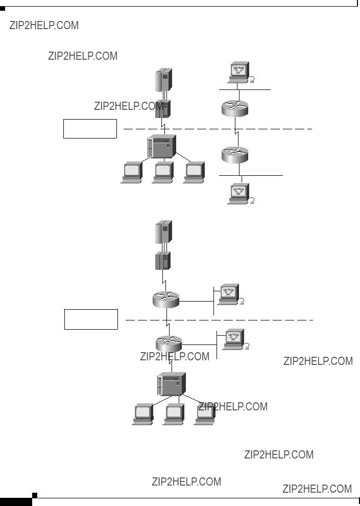
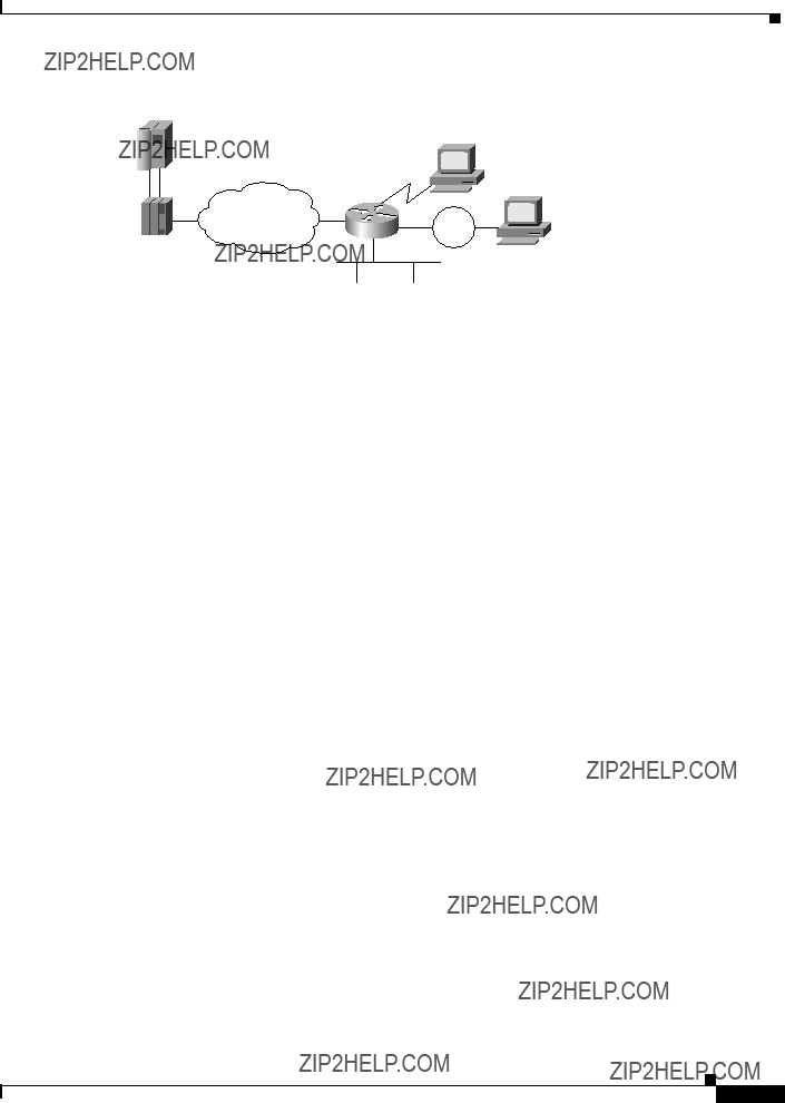
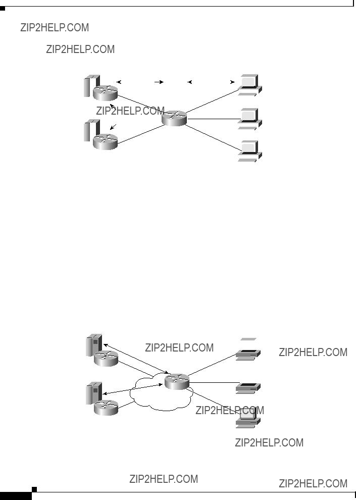
Use IP encapsulation only over a TCP connection within complex meshed networks to support connections between peers that are separated by multiple hops and can potentially use multiple paths, and where performance is not an issue. Use direct encapsulation in point-to-point connections. In a point-to-point configuration, using TCP adds unnecessary processing overhead. Multiple peer types, however, can be combined to in a single router by following the directions for each peer type. For example, for a peer to support both TCP and FST remote-peers, you would need to define both a source-bridge fst peername and a source-bridge remote-peer command for the local router, using the same local IP address.
FST is fast-switched when it receives or sends frames from Ethernet, Token Ring, or FDDI interfaces. It is also fast-switched when it sends and receives from serial interfaces configured with the High-Level Data Link Control (HDLC) encapsulation. In all other cases, FST is slow-switched.
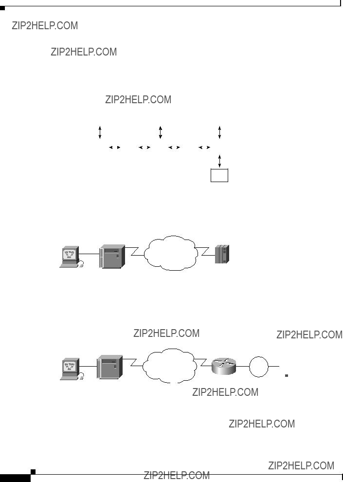
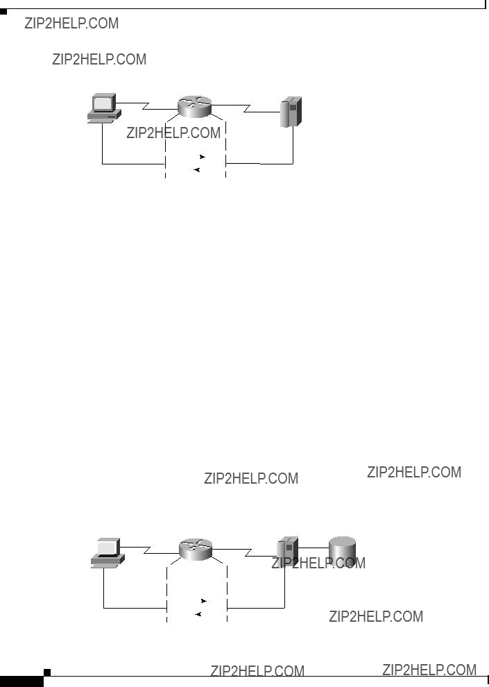
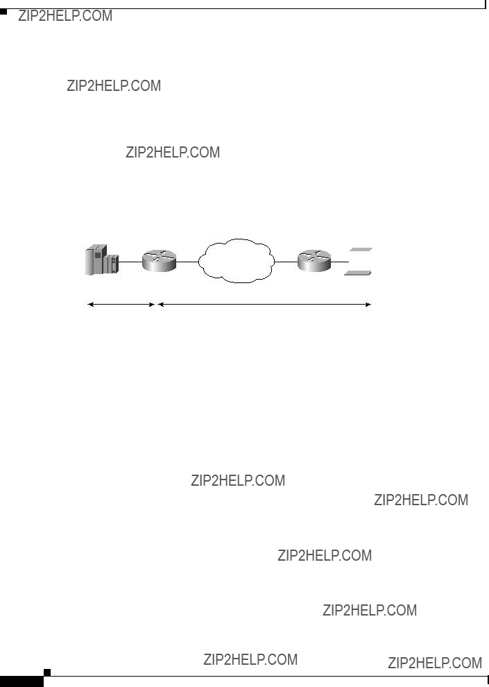
In cases where FST is fast-switched, in either the Cisco routers configured for FST or in the routers contained within the IP ???cloud??? between a pair of FST peers, only one path is used at a given time between the two FST peers. A single path greatly decreases the likelihood that frames arrive out of sequence. In the rare cases where frames do arrive out of sequence, the FST code on the receiving peer discards the out-of-order frame. Thus the Token Ring end hosts rarely lose a frame over the FST router cloud, and performance levels remain adequate.
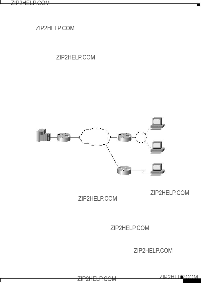
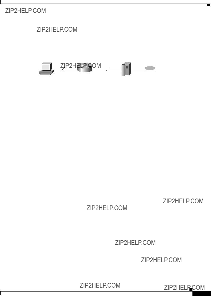
The same conditions are true for any slow-switched topology that provides only a single path (for example, a single X.25 network cloud) between the peers. Similarly, if two slow-switched paths are of very different costs such that one always will be chosen over the other, the chances of having frames received out of sequence are also rare.
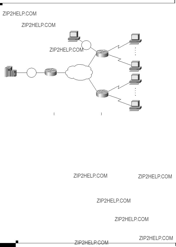
However, if two or more slow-switched paths of equal cost exist between the two routers (such as two parallel X.25 networks), the routers alternate in sending packets between the two or more equal-cost paths. This results in a high probability of frames arriving out of sequence at the receiver. In such cases, the FST code disposes of every out-of-sequence packet, leading to a large number of drops. This requires that the end hosts retransmit frames, greatly reducing overall throughput.
When parallel paths exist, we strongly recommend choosing one as the preferred path. Choose a preferred path by specifying a higher bandwidth for the path that contains the direct connections to the two or more parallel paths on the router.
Do not use FST when the probability exists for frames to lose their order in your network. If you have a network where frames are routinely reordered, it is better to use the TCP protocol for RSRB. TCP provides the overhead necessary to bring frames back in order on the receiving router. FST, to remain fast, does not provide for such a mechanism, and will discard out-of-order frames.
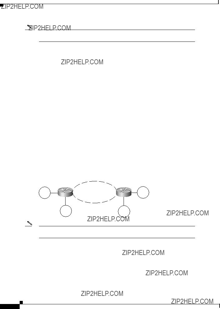
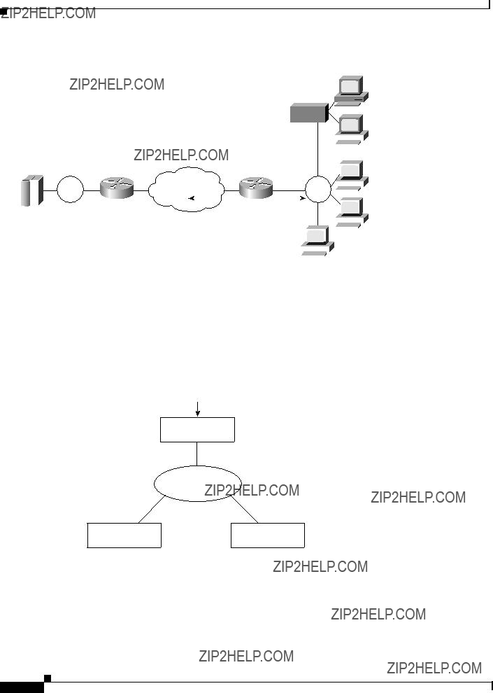
Logical Link Control, type 2 (LLC2) local acknowledgment can be enabled only with TCP remote peers (as opposed to LAN or direct serial interface remote peers) because the Cisco IOS software needs the reliable transmission of TCP to provide the same reliability that an LLC2 LAN end-to-end connection provides. Therefore, the direct media encapsulation options for the source-bridge remote-peer command cannot be used.
If the LLC2 session between the local host and the router terminates on either side of the connection, the other device will be informed to terminate its connection to its local host.
If the TCP queue length of the connection between the two routers reaches 90 percent of its limit, they send Receiver-not-Ready (RNR) messages to the local hosts until the queue limit is reduced to below this limit.
The configuration of the LLC2 parameters for the local Token Ring interfaces can affect overall performance. Refer to the ???Configuring LLC2 and SDLC Parameters??? chapter for more details about fine-tuning your network through the LLC2 parameters.
Cisco IOS Bridging and IBM Networking Configuration Guide


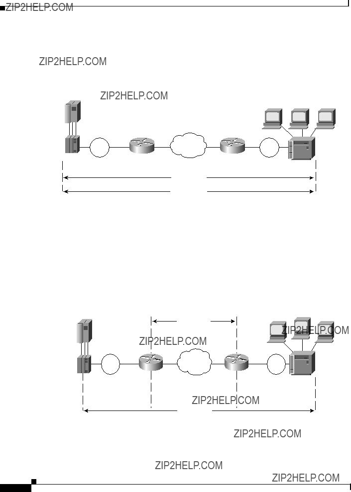
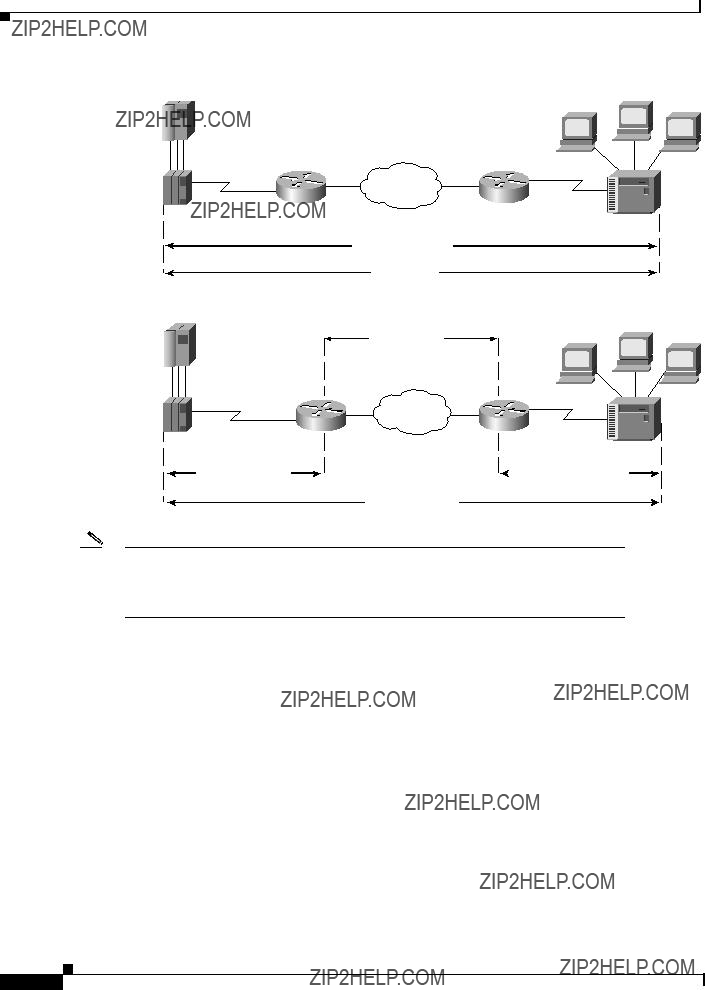
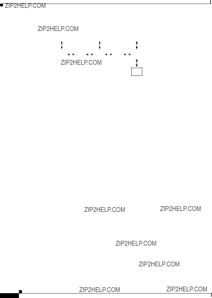
 LLC2 session
 LLC2 session
  S1107a


 S2075
S2075


 S3030
S3030 LLC2 session
 = Virtual Token Ring
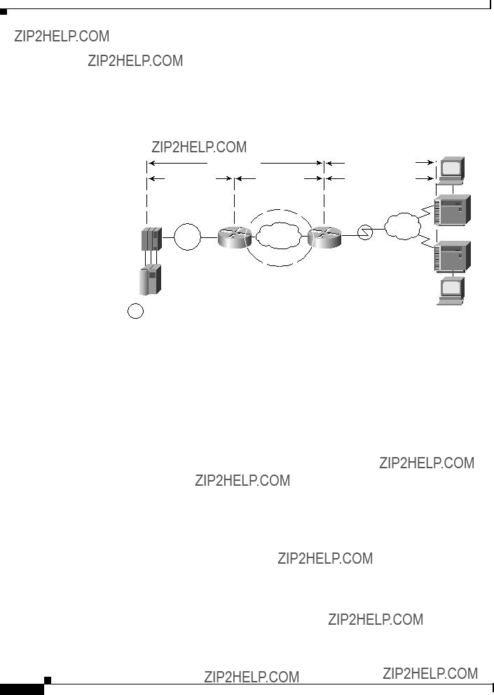


 SNA/HPR directly over
 PU 2.0
 EN
EN LEN
LEN


 27133
27133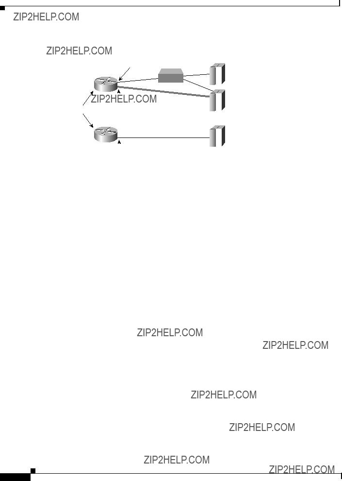


 27990
27990